

Chengdu Diyue Technology SZU06A, SZUO6A User Manual
SZU06A1 Product Manual
SZU06A1 ZIGBEE WIRELESS COMMUNICATION
MODULE
Product Manual

SZU06A1 Product Manual
Table of Contents
Table of Contents....................................................................................................................................................... 1
1 General.................................................................................................................................................................... 1
1.1 Module introduction....................................................................................................................................... 1
1.2 Hardware description......................................................................................................................................1
2 Approvals.................................................................................................................................................................2
2.1 CE Approvals (ETSI).................................................................................................................................... 2
2.2 FCC Approvals..............................................................................................................................................3
2.3 ATEX Approvals............................................................................................................................................4
3 Module Pinout.......................................................................................................................................................6
4 Hardware Description............................................................................................................................................8
4.1 Hardware Diagram.......................................................................................................................................8
4.2 Interface characteristics...............................................................................................................................9
5 Absolute Maximum Ratings................................................................................................................................10
5.1 Environmental characteristics.......................................................................................................................10
5.2 Recommended operating conditions.............................................................................................................11
6 DC Electrical Characteristics..........................................................................................................................11
7 Digital IO Specifications...................................................................................................................................12
8 AC Electrical Characteristics..........................................................................................................................13
9 Physical Dimensions and Footprint............................................................................................................. 15
9.1 Physical Dimensions................................................................................................................................... 15
9.2 Recommended Footprint............................................................................................................................16
10 Soldering Temperature Time Profile (for reflow soldering)................................................................. 17
10.1 Recommended temperature time profile for lead-free solder..............................................................17
11 Reliability Test.....................................................................................................................................................18
12 Application Precautions.................................................................................................................................19
12.1 Safety precautions.....................................................................................................................................19
12.2 Engineering design and using precautions.............................................................................................19
12.3 Storage conditions.....................................................................................................................................20
SZU06A1 PM(Rev 2.0)

SZU06A1 Product Manual
13 Packaging...........................................................................................................................................................21
13.1 Carrier tape...............................................................................................................................................21
13.2 Reel............................................................................................................................................................. 22
14 Ordering Information..........................................................................................................................................23
15 Drawing of Product Label..............................................................................................................................24
16 Disclaimer............................................................................................................................................................25
17 RoHS Declaration.............................................................................................................................................. 25
18 Data Sheet Status..............................................................................................................................................25
19 Reference Documents.......................................................................................................................................26
20 Contact Information............................................................................................................................................26
SZU06A1 PM(Rev 2.0)
SZU06A1 Product Manual
Module features
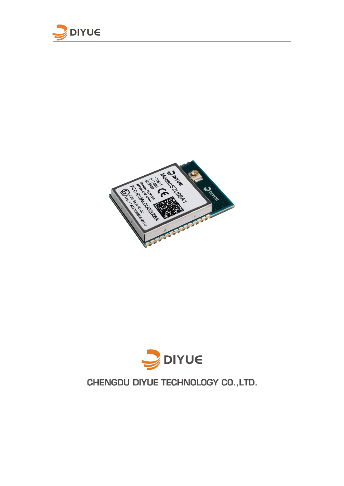
Mini 33-pin stamp-like SMT package
U.FL interface for external SMA antenna
Small form factor: 19 mm x 25 mm x 3.7 mm
Compliant with EU CE certification
Compliant with EU RoHS certification
Compliant with EU ATEX certification
Based on ARM Cortex®-M4 architecture
256K FLASH and 32K RAM
Multiple sleep modes
Operating voltage range: 2.1V to 3.9V
Can act as End Device, Router or
Coordinator
Providing 8 GPIO lines
Providing UART serial communication
interface
Firmware upgrade via serial port
Hardware Supported AES-128 encryption
Storage temperature range: –40ºC to 125ºC
Operating temperature range: –40ºC to 85ºC
Excellent anti-interference ability
Outstanding networking stability
Quick network data processing capability that
collection of data from all nodes can be
completed in 12 seconds in a ZigBee
network composed of 100 nodes
Serial data transmit-receive for end device in
low power mode
Remotely controlling other modules in the
network with commands
ZigBee channel scanning and PANID
scanning
Analyzing topology of current network with
commands
Updating the network key with commands
Acquiring the neighbor table, routing table,
and node information with commands
Switching the current network channel with
commands
Providing abundant module registers for
users to use and providing timers,
interruptions etc. to execute users’ built-in
functions
Scanning of ambient energy values to enable
users to view jamming intensity of network
channel signals
ZigBee multicast function
ZigBee binding function
Providing DIYUE Terminal developed from
the ZigBee PRO property set
Standard JTAG or SWD programming and
real-time online commissioning via IAR
SZU06A1 PM(Rev 2.0)

RF Features
Based on the Silicon Labs EFR32MG1 chip
solution
2.4 GHz ISM frequency band
250 Kbps data transmission rate over the air
16 channels (IEEE802.15.4: CH11–CH26)
Maximum output power: +8dbm
Signal sensitivity: -101dBm@1% PER
Sleep current: 2.7μA
RX current :13.7mA
TX current: 29.7mA @+8dBm
Visible barrier-free communication distance:
1500 m@-69dBm, PER=0.5‰
Smart power grid
Smart Energy
Wireless alarm
Safe home
Smart household
Smart building
Smart agriculture
Wireless sensor network
M2M Industrial control
Lighting, ventilation control
Remote monitoring
Environmental monitoring and control
Contain all of the platform which can quickly
establish a simple Mesh network and
evaluate SZU06A1 ZigBee wireless
communication module performance
AT-style software interface command
dictionary can be modified for high volume
customers.
Custom software development available
upon special request
Applications
SZU06A1 Product Manual
Development kit
SZU06A1 PM(Rev 2.0)

SZU06A1 Product Manual
1
1 General
1.1
Module introduction
1.2
Hardware description
SZU06A1 introduced in this document is an embedded wireless communication module based
on IEEE802.15.4/ZigBee technology. The hardware has taken the EFR32MG1V132 chip
solution of Silicon Labs and the software adopts the SZU06 AT instruction set self developed
based on Ember Z-net_5.9.0 protocol stack released by Silicon Labs.
The advanced hardware design and the simple AT instruction interface enables SZU06A1
ZigBee wireless communication module to be blended into the wide range of applications.
Due to the strong configuration function of SZU06A1 AT instruction set, you can develop the
products without extra MCU to save more time and cost. Besides, SZU06A1 ZigBee wireless
communication module is also an ideal platform for development of ZigBee firmware apart
from the use of customized firmware.
You can add the strong network function into your products without radio frequency experience
or expertise, which can greatly shorten the research and development period of products and
further speed up the marketing of the products.
SZU06A1 ZigBee wireless communication module is composed of the high performance and
low power consumption RF chip EFR32MG1V132 from Silicon Labs, 38.4MHz system clock
crystal oscillator, 32.768KHz monitoring clock oscillator and RF radio frequency front-end
matching circuit which can optimize the radio frequency performance.
The module provides U.FL interface for attaching external SMA interface antenna or PCB
antenna.
The maximum output power of RF chip is 8dBm, and the receive sensitivity is -100dBm
typically.
SZU06A1 PM(Rev 2.0)
SZU06A1 Product Manual
2
Module
Chip
FLAH
RAM
Sealing Dimension
SZU06A1
EFR32MG1V132
256KB
32KB
19mm * 25mm * 3.7mm
2
Approvals
2.1CE Approvals (ETSI)
EMC: Draft ETSI EN 301 489-1 V2.2.0:2017
Radio: EN 300 328 V2.1.1:2016
Safety: EN 60950-1:2006/A11:2009/A1:2010/A12:2011/A2:2013
Type
Product
Manufacturer
wavelength
Impedan
Gain
Antenna
W1010
Pulse Electronics
1/4, dipole
50Ω
2.0dBi
Table 1- 1 Model of SZU06A1 Module
The SZU06A1 is used for ZigBee applications (www.zigbee.org). If you don’t want to use the
AT instruction interface we provided and expect to develop your own software, you need to
download the official Simplicity Studio V4 development tool and Ember Z-net_5.9.0 or later
protocol stack of Silicon Labs.
SZU06A1 ZigBee wireless communication module is certified CE by the following standards:
Draft ETSI EN 301 489-17 V3.2.0:2017
EN 62479:2010
The information of antennae for tests is shown in the following table:
Table 2- 1 Approved Antennae
When SZU06A1 ZigBee wireless communication module is embedded into an OEM product, it
is prohibited to declare that his OEM products comply with CE certification in the name of
approved CE certification of our company. If the OEM manufacturer wants to declare that his
final products comply with CE certification, it must be ensured that the final products shall
comply with the European EMC, Radio and Safety standards. Otherwise, ChengDu DiYue
Technology Co., Ltd. has the right to investigate and affix the responsibility for it.
SZU06A1 PM(Rev 2.0)
SZU06A1 Product Manual
3
2.2FCC Approvals
The SUZ06A1 ZigBee wireless communication module including the antenna listed is Table
2-1 have been tested to comply with Part 15 of the FCC rules.
FCC caution:
Note:
This equipment has been tested and found to comply with the limits for a Class B digital device,
pursuant to Part 15 of the FCC Rules. These limits are designed to provide reasonable
protection against harmful interference in a residential installation. This equipment generates,
uses and can radiate radio frequency energy and, if not installed and used in accordance with
the instructions, may cause harmful interference to radio communications. However, there is
no guarantee that interference will not occur in a particular installation. If this equipment does
cause harmful interference to radio or television reception, which can be determined by turning
the equipment off and on, the user is encouraged to try to correct the interference by one or
more of the following measures:
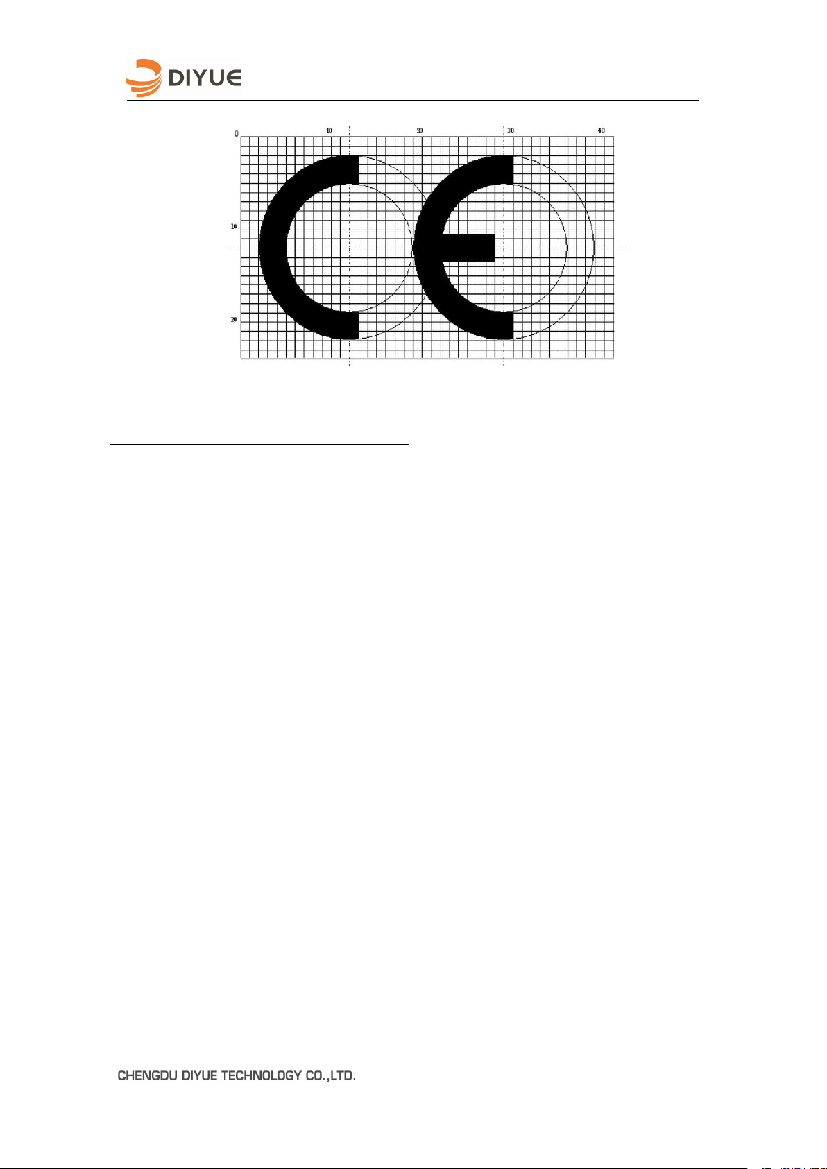
The "CE" marking must be placed in a prominent position of OEM products. Please refer to
http://ec.europa.eu/enterprise/faq/ce-mark.htm for more information about CE certification
mark.
This device complies with Part 15 of the FCC rules. Operation is subject to the following
two conditions: (1) this device may not cause harmful interference, and (2) this device
must accept any interference received, including interference that may cause undesired
operation.
SZU06A1 PM(Rev 2.0)
SZU06A1 Product Manual
4
Reorient or relocate the receiving antenna.
Increase the separation between the equipment and receiver.
Connect the equipment into an outlet on a circuit different from that to which the receiver is
Consult the dealer or an experienced radio/TV technician for help.
Please take attention that changes or modification not expressly approved by the party
2.3ATEX Approvals
The SZU06A1 ZigBee wireless communication module has been tested to comply with the
ATEX 2014/34/EU regulation about explosion proof products. Intended Use:Zone 2 GAS.
This device meets the following parameters:
i i i i i s
U =3.9V, I =1A, P=0.98W, C =15.32μF, L =5.64μH, -40 T 80 . ℃ ℃
And it complies with the following standard:
EN 60079-0:2012+A11:2013
EN 60079-11:2012
When installing the SZU06C1 module into your own product and requiring explosion protection,
please make sure that your product must meet the above explosion-proof parameters and
indicate "Transceiver Module II 3G Ex ic IIC Gc" or similar words outside the final product.
connected.
responsible for compliance could void the user’s authority to operate the equipment.
FCC RF EXPOSURE STATEMENT:
The device has been evaluated to meet general RF exposure requirement, The device
can be used in portable exposure condition without restriction.
Ex marking:
Certificate number:
SZU06A1 PM(Rev 2.0)

SZU06A1 Product Manual
5
Name And Address Of Notified Body: TÜV SÜD Product Service GmbH
Zertifizierstellen
Ridlerstraße 65
80339 MÜNCHEN
GERMANY
Number Of Notified Body: 0123
Special conditions for safe use:
1. The sign “U“ placed after the certificate number indicates that the certificate must not
be mistaken with a certificate intended for an equipment or protective system. This
partial certification may be used as a basis for certification of equipment or protective
system.
2. The maximum input parameters stated above shall be considered during installation.
The rules for interconnection of intrinsically safety circuits according EN 60079-11 and
EN 60079-14 have to be taken into account.
3. The maximum service temperature of the communication module when incorporated
into apparatus is -40°C to +80°C. When utilized at this service temperature, a T4
temperature classification is suitable.
4. The communication module shall be installed in an enclosure that provides a minimum
ingress protection of IP20.
SZU06A1 PM(Rev 2.0)
 Loading...