

Page 1

SR209 Plus Series
Server Chassis User Manual
November 2019 Version 2.1
A document provides an overview of product features, functions, architecture, and support specifications
Page 2

SR209 Plus Series
│ 2
DISCLAIMERS
No license (express or implied, by estoppel or otherwise) to any intellectual property rights is granted by this document.
Chenbro disclaims all express and implied warranties, including without limitation, the implied warranties of merchantability, fitness
for a particular purpose, and non-infringement, as well as any warranty arising from course of performance, course of dealing, or
usage in trade.
This document contains information on products, services and/or processes in development. All information provided here is subject
to change without notice. Contact your Chenbro representative to obtain the latest Configuration Guide.
The products and services described may contain defects or errors known as errata which may cause deviations from published
specifications. Current characterized errata are available on request.
Chenbro, and the Chenbro logo are trademarks of Chenbro Micom Co., Ltd. in the worldwide.
*Other names and brands may be claimed as the property of others
© 2019 Chenbro Micom Co., Ltd.
Page 3

SR209 Plus Series
│ 3
Table of Contents
List of Figures ................................................................................................................................................ 4
List of Tables ................................................................................................................................................. 5
1. Product Overview .......................................................................................................................... 6
1-1 Front Panel .............................................................................................................................. 7
1-2 Back Panel ............................................................................................................................... 8
1-3 Security Features ..................................................................................................................... 9
1-4 Front Control Panel ............................................................................................................... 10
1-5 Chassis Dimensions ............................................................................................................... 11
1-6 Interior View ......................................................................................................................... 12
1-7 System Level Environmental Specifications ............................................................................ 13
1-8 System Packaging ................................................................................................................. 14
2. System Components Installation and Removal ............................................................................ 15
2-1 Side Cover Installation ........................................................................................................... 15
2-2 Front Bezel Installation .......................................................................................................... 16
2-3 5.25” Device Installation ........................................................................................................ 17
2-4 HDD Cage Installation ............................................................................................................ 19
2-5 Optional Fan (Add-In-Card Area) Installation ......................................................................... 24
2-6 Rear Fan Maintenance ........................................................................................................... 25
2-7 Power Supply Installation ...................................................................................................... 26
3. Backplane .................................................................................................................................... 27
3-1 Storage Backplane Options .................................................................................................... 28
3-2 3.5” 12Gbps Mini-SAS Backplane ........................................................................................... 29
3-3 3.5” 12Gbps 4-Port SAS/SATA Backplane................................................................................ 32
4. Maintenance and Service ............................................................................................................ 35
Page 4

SR209 Plus Series
│ 4
List of Figures
Figure 1 Front panel (enclosed) ................................................................................................................ 7
Figure 2 Front panel (open) ...................................................................................................................... 7
Figure 3 Back panel with redundant PSU .................................................................................................. 8
Figure 4 Key lock and Kensington slot location ......................................................................................... 9
Figure 5 Intrusion switch location ............................................................................................................ 9
Figure 6 Front control panel ................................................................................................................... 10
Figure 7 Front control panel ................................................................................................................... 10
Figure 8 Chassis dimensions ................................................................................................................... 11
Figure 9 Chassis components ................................................................................................................. 12
Figure 10 Side cover installation ............................................................................................................... 15
Figure 11 Bezel installation ...................................................................................................................... 16
Figure 12 Bezel removal ........................................................................................................................... 16
Figure 13 5.25” device blank removal ...................................................................................................... 17
Figure 14 5.25” device side rail installation .............................................................................................. 17
Figure 15 5.25” device installation ........................................................................................................... 18
Figure 16 3.5” internal HDD cage installation ........................................................................................... 19
Figure 17 3.5” hot-swap HDD cage installation ......................................................................................... 19
Figure 18 3.5” hot-swap HDD cage fan maintenance step-1 ..................................................................... 20
Figure 19 3.5” hot-swap HDD cage fan maintenance step-2 ..................................................................... 20
Figure 20 3.5” hot-swap HDD carrier removal .......................................................................................... 21
Figure 21 3.5” hot-swap HDD carrier installation ...................................................................................... 21
Figure 22 3.5” HDD installation (tool-less type) ........................................................................................ 22
Figure 23 3.5” HDD installation (screw type) ............................................................................................ 22
Figure 24 2.5” SSD installation (screw type) ............................................................................................. 23
Figure 25 Optional fan installation ........................................................................................................... 24
Figure 26 Optional fan removal ................................................................................................................ 24
Figure 27 Rear fan maintenance step-1 .................................................................................................... 25
Figure 28 Rear fan maintenance step-2 .................................................................................................... 25
Figure 29 Single PSU installation .............................................................................................................. 26
Figure 30 Drive carrier LED identification ................................................................................................. 27
Figure 31 Backplane front view ................................................................................................................ 29
Figure 32 Backplane rear view ................................................................................................................. 30
Figure 33 Backplane front view ................................................................................................................ 32
Figure 34 Backplane front view ................................................................................................................ 33
Figure 35 Backplane rear view ................................................................................................................. 33
Page 5

SR209 Plus Series
│ 5
List of Tables
Table 1 Chenbro SR209 Plus specifications ............................................................................................... 6
Table 2 Front control panel .................................................................................................................... 10
Table 3 System environmental specifications summary .......................................................................... 13
Table 4 System packing information ....................................................................................................... 14
Table 5 Product weight information ....................................................................................................... 14
Table 6 Drive power LED/activity LED behavior ...................................................................................... 27
Table 7 Backplane specifications ............................................................................................................ 29
Table 8 Connector and pin header function description ......................................................................... 30
Ta ble 9 Backplane specifications ............................................................................................................ 32
Table 10 Connector and pin header function description ......................................................................... 34
Page 6

SR209 Plus Series
│ 6
1. Product Overview
The SR209 chassis has been modified to support both tool-less 3.5” HDD carrier and PCIe 3.0 slot, and transformed to feature-
advanced SR209 Plus. Beneath the chassis, an information sticker reads revision and manufacturing code, necessary for technical
support.
Table 1 Chenbro SR209 Plus specifications
Feature
Description
MB Form Factor
ATX (12” x 9.6")
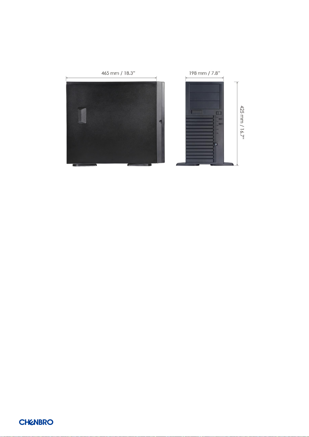
Dimension
(Dx W x H)
465.0 x 198.0 x 425.0 (mm)
18.31” x 7.80” x 16.73” (w/o bezel)
Drive Bay
3 x 5.25" External, 4 x 3.5" Hot-swap (Option), 4 x 3.5” Internal (Option)
Storage Backplane
1 x 3.5" 4-port 12Gbps Mini-SAS HD Passive Backplane
1 x 3.5" 4-port 12Gbps SAS/SATA Passive Backplane
PSU Form Factor
PS/2 Single or N+1 Redundant
Indicator
1 x Power Status, 2 x LAN Activity, 1 x HDD Status, 1 x System Alarm
Front Control
1 x Power On/Off, 1 x System Reset, 1 x Alarm Mute, 2 x USB2.0/USB3.0 (Option)
Cooling Fan
HDD Cage: 80 x 25 mm (1), PCI: 80 x 25 mm (1) (Option), Rear: 120 x 25 mm (1)
System Security
Intrusion Switch, Key Lock, Kensington Slot
Expansion Slot Opening
7 x Full Height (5 x Full Length + 2 x Half Length)
Net Weight
7.8 kg/17.18 lb
Gross Weight
9.8 kg/21.59 lb
Cubic Feet
2.94
Container Loading
20’: 350, 40’: 734, 40’H: 820
Slide Rail
Supported
Page 7
SR209 Plus Series
│ 7
1-1 Front Panel
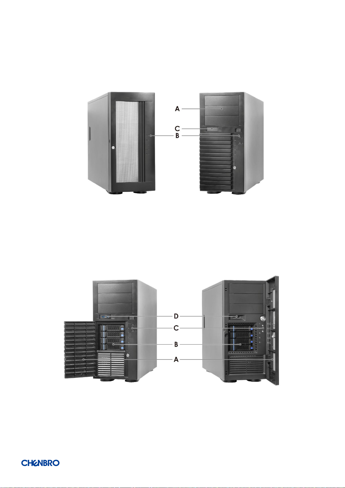
Figure 1 Front panel (enclosed)
A. 5.25” Storage Drive Bay
B. Front Control Panel
C. USB Port Blank
Figure 2 Front panel (open)
A. Bezel Door
B. 3.5” Storage Drive Bay
C. Front Control Panel
D. USB3.0
Page 8
SR209 Plus Series
│ 8
1-2 Back Panel
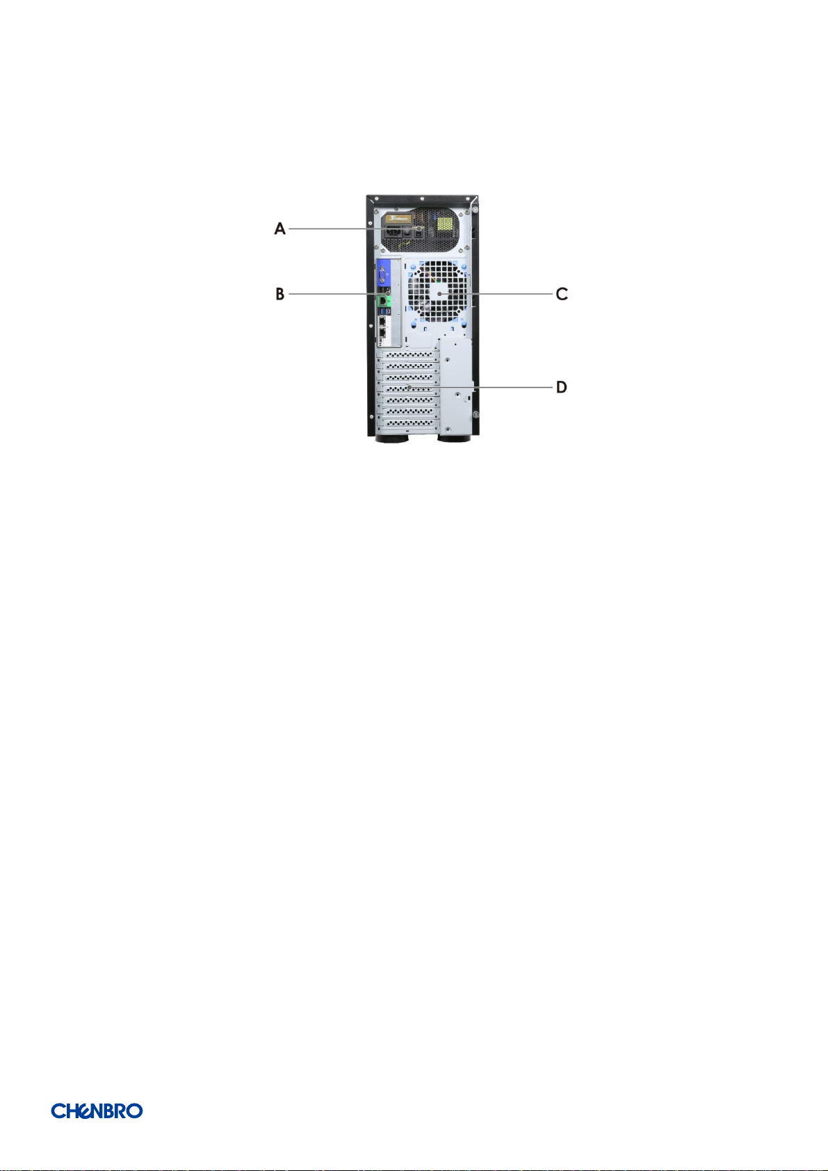
Figure 3 Back panel with redundant PSU
A. 1+1 Redundant PSU
B. Rear I/O
C. Rear Fan
D. Expansion Slot Opening
Page 9
SR209 Plus Series
│ 9
1-3 Security Features
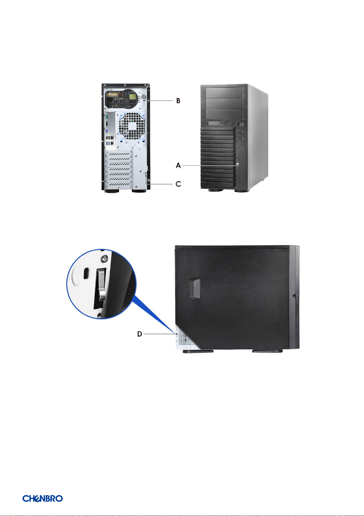
Figure 4 Key lock and Kensington slot location
Figure 5 Intrusion switch location
A. Key Lock
B. Side Cover Lock
C. Kensington Slot
D. Intrusion Switch
Page 10
SR209 Plus Series
│ 10
1-4 Front Control Panel
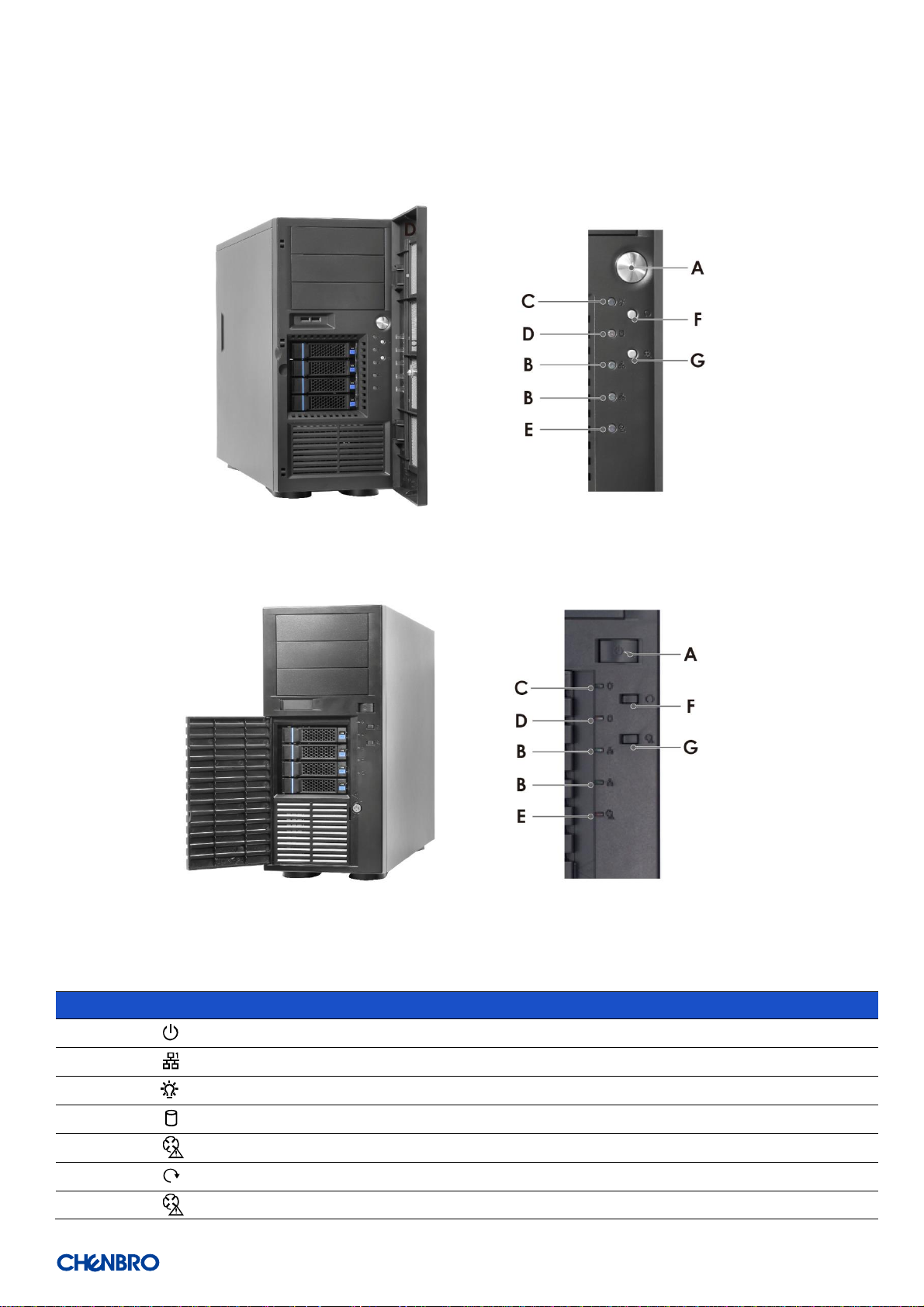
Figure 6 Front control panel
Figure 7 Front control panel
Table 2 Front control panel
Label
ICON
Indicator, button or connector
A Power Button
B LAN1, LAN2 Activity LED
C Power LED
D
HDD Activity LED
E
Fan Alarm LED
F
System Reset Button
G
Fan Alarm Reset Button
Page 11
SR209 Plus Series
│ 11
1-5 Chassis Dimensions
Figure 8 Chassis dimensions
Page 12

SR209 Plus Series
│ 12
1-6 Interior View
Figure 9 Chassis components
A. 3.5” HDD Cage Slot
B. Power Supply Unit
C. 5.25” Storage Drive Bay
D. PCIe Fan (Option)
E. System Board
Page 13

SR209 Plus Series
│ 13
1-7 System Level Environmental Specifications
The following table defines the system level specification under operating and non-operating environment.
Table 3 System environmental specifications summary
Parameter
Specification
Temperature
Operating
5º C to 35º C (41º F to 95º F)
Temperature
Non-Operating
-40º C to 70º C (-40º F to 158º F)
Humidity
Non-Operating
50% to 90%, non-condensing with a maximum wet bulb of 28° C (at temperatures
from 25° C to 35° C)
Unpackaged
Shock
Non-Operating
Trapezoidal, 25 g, velocity change is based on product weight
Vibration
Operating
5 Hz @ 0.0002 g2/Hz to 350 Hz @ 0.0002 g2/Hz
Input acceleration is 0.26 g RMS
10 minutes per axis for all 3 axes on all samples
Random control limit tolerance is ± 3 dB
Sag & Bow
Non-Operating
Tolerance analysis among rack, rail and chassis
Actual on rack test with EIA Go-NoGo fixture
EMI
Pre-scan
Radiated Emissions
CISPR CLASS A (under 6dB):
30~1000 MHz vertical/horizontal
1G~6G GHz vertical/ horizontal
1G~18G GHz vertical/horizontal
RVI
Operating
HDD class
Class 1: Highest performance, reliability, and data integrity
Class 2: A second tier of performance, reliability, and data integrity
HDD I/O throughput degradation SPEC
Pass/Fail Criteria
No functional failure during test or post-test diagnostics.
Requirement to pass test is based on IOMeter data throughput (in IO’s per
second) expressed as a percent of Test HDD maximum theoretical baseline
performance
Class1: > 90% of baseline for 4K random writes and > 80% of baseline for
128K sequential writes.
Class2: > 85% of baseline for 4K random writes and > 75% of baseline for
128K sequential writes.
Mix: > 80% of baseline for 4K random writes and > 70% of baseline for
128K sequential writes.
Packaged
Vibration
Non-Operating
ISTA (weight over 68 kg, 1B; weight equal or less than 68 kg, 1A)
Packaged Drop
Non-Operating
Drop height change is based on product weight
Non-palletized product:
Investigation: Test requirement is 6 face drops, 8 corner drops and 12 edge
drops for a total of 26 drops.
Validation: Test requirement is 6 face drops, 2 corner drops and 3 edge
drops for a total of 11 drops.
Palletized product: (Both investigation and validation)
Perform two bottom drops at the specified height, 10 bottom drops at one
half of the specified height.
Perform 4 rotational edge drops (one per edge) at the specified height.
Page 14

SR209 Plus Series
│ 14
1-8 Syst em Packaging
The original Chenbro packaging, where the server system is delivered, is designed to provide protection to a fully configured system
and tested to meet ISTA (International Safe Transit Association) Test Procedure 1A. The packaging is also designed to be re-used for
shipment after system integration has been completed.
The original packaging includes –the shipping box, and various protective inner packaging components, which are designed to
function together as a protective packaging system. When reused, all of the original packaging material must be used, including box
and each inner packaging component. In addition, all inner packaging components MUST be re-installed in the proper location to
ensure adequate protection of the system for subsequent shipment.
Table 4 System packing information
Part Number
Single/Bulk
Form Factor (mm)
Support Level
387-20969-2100A0
Single
350 x 734 x 820
L5
NOTE: The design of the inner packaging components does not prevent improper placement within the packaging assembly.
There is only one correct packaging assembly that will allow the package to meet the ISTA (International Safe Transit Association)
Test Procedure 1A (2008). Failure to follow the specified packaging assembly instructions may result in damage to the system
during shipment.
Table 5 Product weight information
Product
Unpackaged Net Weight
(kg)
Packaged Gross Weight
(kg)
Unpackaged Net Weight
(lb)
Packaged Gross Weight
(lb)
SR209 Plus
7.8
9
17.18
9.8 21.59
NOTE: A L5 system does not include motherboard, processors, memory, drives, or add-in cards. It is the system
configuration as shipped from Chenbro. Weights of integrated system (system configurations that include the items
above) will vary depending on the final system configuration.
Page 15

SR209 Plus Series
│ 15
2. System Components Installation and Removal
SR209 Plus supports up to 4 x 3.5” hot-swap SAS/SATA HDD or 4 x 3.5” Internal SAS/SATA HDD. Support for different storage and
peripheral options will vary depending on the system model and/or available accessory options installed.
2-1 Side Cover Installation
Figure 10 Side cover installation
1. Insert the cover along the bottom groove.
2. Place down the cover towards the chassis.
3. Secure the thumb screws on the top and bottom.
Page 16

SR209 Plus Series
│ 16
2-2 Front Bezel Installation
Figure 11 Bezel installation
1. Lean the right side of the bezel on the front chassis.
2. Fully attach the bezel on the front of the chassis, and make sure the internal latches (x 2) are up.
3. Push down the bezel until it is secured.
Figure 12 Bezel removal
1. Lift the internal latches (x 2) up.
2. Detach the bezel tabs and remove the bezel.
Page 17

SR209 Plus Series
│ 17
2-3 5.25” Device Installation
Figure 13 5.25” device blank removal
1. Press two sides of the latch of the blank to release the blank as shown.
2. Pull the blank out.
Figure 14 5.25” device side rail installation
1. Take the reserved side rails located inside the drive slot.
2. Attach and secure the side rail on both sides of the 5.25” device.
Page 18

SR209 Plus Series
│ 18
Figure 15 5.25” device installation
1. Insert the 5.25” device into the drive bay.
Note: Make sure both side rails are clipped on the latch.
Page 19

SR209 Plus Series
│ 19
2-4 HDD Cage Installation
Figure 16 3.5” internal HDD cage installation
1. Insert the fan into the reserved slot.
2. Insert the HDD cage into the chassis.
3. Secure the thumb screws on the four sides of the HDD cage.
4. Plug the fan power connector into the system board.
Figure 17 3.5” hot-swap HDD cage installation
1. Insert the HDD cage into the chassis.
2. Secure the thumb screws on the four sides of the HDD cage.
Page 20

SR209 Plus Series
│ 20
Figure 18 3.5” hot-swap HDD cage fan maintenance step-1
Figure 19 3.5” hot-swap HDD cage fan maintenance step-2
1. Unplug the power connector from the backplane.
2. Release the fan latch and pull the fan out of the fan cage.
3. Remove the tool-less fan holder as shown and replace with a new fan.
4. Insert the fan into the fan cage.
5. Make sure the power connector go through the hole on the other side of the fan cage.
6. Plug the power connector into the backplane.
Page 21

SR209 Plus Series
│ 21
Figure 20 3.5” hot-swap HDD carrier removal
1. Press the carrier button to release the carrier.
2. Pull the lever to remove the carrier from the HDD cage.
Figure 21 3.5” hot-swap HDD carrier installation
1. Insert the HDD carrier into the cage.
2. Push down the lever to secure the HDD carrier.
Page 22

SR209 Plus Series
│ 22
Figure 22 3.5” HDD installation (tool-less type)
1. Engage two embossed pins into the side dimples on the HDD as shown
2. Carefully push down the other side of the HDD until another two embossed pins and side dimples lock into place
NOTE: Due to degraded performance and reliability concerns, the use of the 3.5” drive blank filler as a 2.5” device bracket is
intended to support SSD type storage devices only. Installing a 2.5” hard disk drive into the 3.5” drive carrier cannot be
supported.
Figure 23 3.5” HDD installation (screw type)
1. Align front HDD with the anchor point on the carrier.
2. Assemble 3.5” HDD with carrier by four screws as shown.
Page 23

SR209 Plus Series
│ 23
Figure 24 2.5” SSD installation (screw type)
1. Align front HDD with the anchor point on the carrier.
2. Assemble 2.5” SSD into the carrier by three screws from the bottom as shown.
Page 24

SR209 Plus Series
│ 24
2-5 Optional Fan (Add-In-Card Area) Installation
Figure 25 Optional fan installation
1. Attach the fan with the tool-less fan holder (as shown).
2. Insert the fan module into the reserved fan slot as shown.
NOTE: Please notice the arrow on the fan holder pointing the rear.
3. Plug the power connector into the system board.
Figure 26 Optional fan removal
1. Unplug the power connector.
2. Release the fan latch and pull the fan out.
3. Remove the tool-less fan holder as shown and replace the fan.
Page 25

SR209 Plus Series
│ 25
2-6 Rear Fan Maintenance
Figure 27 Rear fan maintenance step-1
Figure 28 Rear fan maintenance step-2
1. Lift up the fan latch at the bottom of the fan module without release.
2. Push the fan module down to remove it from the chassis.
3. Remove the fan from the tool-less fan holder as shown and replace the fan.
4. Secure the fan module by aligning four embossed pins with four holes on the chassis, and pushing it upwards as shown.
Page 26

SR209 Plus Series
│ 26
2-7 Power Supply Installation
Figure 29 Single PSU installation
1. Place the PSU inside the chassis, and ensure the alignment for four screw holes of PSU and bracket of the chassis matched.
2. Secure the four screws as shown.
Page 27

SR209 Plus Series
│ 27
3. Backplane
Each drive carrier includes separate LED indicators for drive activity and drive status. Light pipes integrated into the drive carrier direct
light emitted from the LEDs mounted next to each drive connector on the backplane to the drive carrier faceplate, making them
visible from the front of the system.
Figure 30 Drive carrier LED identification
Table 6 Drive power LED/activity LED behavior
LED
ICON
LED
Color
Behavior
Condition
A,C Power LED
N/A
Stay off
Fault
Blue
Solid on
Present
B,D Activity LED
Green
Solid on
Access
Red
Solid on
Failure
1Hz blink
Rebuild
4Hz blink
Locate
NOTE: The drive activity LED is driven by signals coming from the drive itself. Drive vendors may choose to operate the activity
LED differently from what is described in the table above. Should the activity LED on a given drive type behave differently than
what is described, customers should take the drive vendor specifications as a reference for the specific drive model to determine
what the expected drive activity LED operation should be.
Page 28

SR209 Plus Series
│ 28
3-1 Storage Backplane Options
SR209 Plus supports the below bac kplanes:
1 x 3.5” 12Gbps Mini-SAS HD backplane
1 x 3.5” 12Gbps 4-port SAS/SATA backplane
All available SAS/SATA compatible backplanes include the following common features:
12Gbps SAS and 6Gbps SAS/SATA
29-pin SFF-8680 12Gbps rated drive interface connectors, providing both power and I/O signals to attached devices
Hot-swap support for SAS/SATA devices
I2C interface from a 4-pin connector for device status communication to the BMC over SMBus
LEDs to indicate drive activity and status for each attached device
Page 29

SR209 Plus Series
│ 29
3-2 3.5” 12Gbps Mini-SAS Backplane
Table 7 Backplane specifications
Specification
Host Interface
SFF-8643
HDD Interface
SFF-8680
Hot-Swap
Yes, allows users to replace devices online
Display
LED indicates storage device status
Power LED – Blue (Present)
Access LED – Green (Busy)
Error LED – Red (Error)
Environment Monitor
Temperature sensor TMP75
Connector
1. 1 x Mini-SAS HD
2. 4 x SFF-8680 SAS
3. 2 x 4-pin peripheral power connector for +5V, +12V from power supply
4. 1 x PIN Header 2.54 mm (2 x 3)
5. 1 x Wafer 2.5 mm (4P)
6. 2 x Wafer 2.54 mm (2P)
7. 2 x Wafer 2.54 mm (4P)
8. 1 x I2C
Dimension (D x W x H)
106.0 x 114.0 x 2.4 mm
Material
FR4 4 layers
Figure 31 Backplane front view
A. HDD_00
B. HDD_01
C. HDD_02
D. HDD_03
Page 30

SR209 Plus Series
│ 30
Figure 32 Backplane rear view
Table 8 Connector and pin header function description
Label
Description
Description
Drawing
A
Mini-SAS HD
For connecting to a mainboard or a HBA, this mini-SAS
HD connector is applied. A proper cable selection is
essential as well to make sure good signal integrity can
be maintained for the whole connection path from
mainboard or HBA/RAID card to the HDD devices.
B
Power
These two connectors are used to power four 3.5” hard
disks, connected to this backplane, and each can
ensure that all drives are supplied with stable power
inputs. If the chassis fan is also powered by fan header
(JF01), this configuration is highly recommended.
C
Fan
There are two 4-pin headers for the PWM fan, and it is
alternative solution that the chassis fan can be
powered and monitored by this backplane instead of
motherboard. If the chassis fan is connected to
mainboard, user needs to disable the fan monitoring
function of backplane by DIP switch (SW1).
D
Signal indicator
The event LED, with red/black wire, is located on front
bezel of SR209 Plus, and can be configured through
this pin header.
E
Power fail mute
Transfer mute signal from backplane to PSU
F
Power fail alarm
Send alarm signal to PSU.
G
Buzzer
Buzzer will alarm when fan and temperature become
abnormal
Page 31

SR209 Plus Series
│ 31
Label
Description
Description
Drawing
H
DIP switch
The settings of on-board hardware monitor can be
controlled and configured through this DIP switch. It
can manage the functions of PWM fan & temperature
threshold.
I
I2C
The motherboard can monitor HDD temperature and
fan status through this connector. However, the I2C
connector on motherboard side is vendor dependent,
so please contact our field application engineers to
fully utilize this feature.
Page 32

SR209 Plus Series
│ 32
3-3 3.5” 12Gbps 4-Port SAS/SATA Backplane
Table 9 Backplane specifications
Figure 33 Backplane front view
A. HDD_00 C. HDD_02
B. HDD_01 D. HDD_03
Specification
Host Interface
7-pin SATA
HDD Interface
SFF-8680
Hot-Swap
Yes, allows users to replace devices online
Display
LED indicates storage device status
Power LED – Blue (Present)
Access LED – Green (Busy)
Error LED – Red (Error)
Environment Monitor
Temperature sensor TMP75
Connector
1. 4 x SATA
2. 4 x SAS29
3. 4 x Big 4P Power connectors for +5V, +12V from power supply
4. 1 x Pin Header 2.0 mm (1 x 3)
5. 1 x PIN Header 2.0 mm (2 x 3)
6. 1 x PIN Header 2.54 mm (2 x 3)
7. 1 x PIN Header 2.54 mm (2 x 5)
8. 1 x Wafer 2.5 mm (4P)
9. 2 x Wafer 2.54 mm (2P)
10. 1 x Wafer 2.54 mm (4P)
Dimension (D x W x H)
106.0 x 114.0 x 2.4 mm
Material
FR4 4 layers
Page 33

SR209 Plus Series
│ 33
Figure 34 Backplane front view
A. HDD_00 C. HDD_02
B. HDD_01 D. HDD_03
Figure 35 Backplane rear view
Page 34

SR209 Plus Series
│ 34
Table 10 Connector and pin header function description
Label
Description
Description
Drawing
A
SATA/SAS
For connecting to a mainboard, this 7-pin SATA/SAS
connector is applied. A proper cable selection is essential as
well to make sure good signal integrity can be maintained for
the whole connection path from mainboard HDD devices.
B
Power
These two connectors are used to power four 3.5” hard disks,
connected to this backplane, and each can ensure that all
drives are supplied with stable power inputs. If the chassis fan
is also powered by fan header (JF01), this configuration is
highly recommended.
C
Fan
There are two 4-pin headers for the PWM fan, and it is
alternative solution that the chassis fan can be powered and
monitored by this backplane instead of motherboard. If the
chassis fan is connected to mainboard, user needs to disable
the fan monitoring function of backplane by DIP switch
(SW1).
D
Signal indicator
The event LED with red/black wire is located on front bezel
of SR209 Plus and can be configured through this pin header.
E
Power fail mute
Transfer mute signal from backplane to PSU
F
Power fail alarm
Send alarm signal to PSU
G
Buzzer
Buzzer will alarm when fan and temperature become
abnormal
H
DIP switch
The settings of on-board hardware monitor can be controlled
and configured through this DIP switch. It can manage the
functions of PWM fan & Buzzer On/Off.
I
I2C
The motherboard can monitor HDD temperature and fan
status through this connector. However, the I2C connector
on motherboard side is vendor dependent, so please contact
our field application engineers to fully utilize this feature.
Page 35

SR209 Plus Series
│ 35
4. Maintenance and Service
DOA (Dead on Arrival)
If the products are found Defect On Arrival, please contact Chenbro’s regional sales or CQE and indicate the defective status via email
along with product photos and description. You may need to return the defective item by request.
The customer should ensure that the products are Defect On Arrival for up to three months from Chenbro’s shipping date and the
damage is not caused by shipping or failures resulting from accident, misuse, abuse, neglect, mishandling, misapplication,
modification, improper operation, improper repair or rework. CHENBRO is not responsible for the cost of replacement including the
delivery cost.
CHENBRO also reserves the right to examine the DOA products. If the damage of DOA products is caused by improper action as
described above, the customer will be liable for paying the related charge having occurred or paying the fee of the replacements if
the DOA products are totally scrapped.
TECHNICAL SUPPORT
Please provide following information when you apply our technical support:
⚫ Product model name and/or part number
⚫ Product serial number and bar code
⚫ Buzzer beeping pattern and/or failure LED flashing pattern
⚫ Detailed, specific questions
You may also contact Chenbro’s regional technical supports as below: www.chenbro.com
CENBRO MICOM CO., LTD.
Email: fae@chenbro.com
Tel: +886-2-82265500
Fax: +886-2-82265392
CHENBRO MICOM (USA) INC.
Email: usfae@chenbro.com
Tel: +1-909-947-3200
Fax: +1-909-947-4300
CHENBRO GmbH
Email: defae@chenbro.com
Tel: + 49-2154-8142730
Apply a RMA
number
Return the product for
repair
Receive service
charge notice
Receive the repaired
product
 Loading...