

Page 1

RM138 Series
Rackmount Chassis User Manual
February 2019 Version 1.0
A d ocument provides an overview of product f eatures, functions, archit ecture, and support specifications
Page 2

RM138 Series
DISCLAIMERS
No license (express or implied, by estoppel or otherwise) to any intellectual property rights is granted by this document.
Chenbro disclaims all express and implied warranties, including without limitation, the implied warranties of merchantability, fitness
for a particular purpose, and non-infringement, as well as any warranty arising from course of performance, course of dealing, or
usage in trade.
This document contains information on products, services and/or processes in development. All information provided here is subject
to change without notice. Contact your Chenbro representative to obtain the latest Configuration Guide.
The products and services described may contain defects or errors known as errata which may cause deviations from published
specifications. Current characterized errata are available on request.
Chenbro, and the Chenbro logo are trademarks of Chenbro Micom Co.,Ltd in the worldwide.
*Other names and brands may be claimed as the property of others
© 2019 Chenbro Micom Co.,Ltd.
<Table of Contents │ 2
Page 3

RM138 Series
Table of Contents
Table of Contents .......................................................................................................................................... 3
List of Figures ................................................................................................................................................ 4
List of Tables ................................................................................................................................................. 6
1. Product Overview .......................................................................................................................... 7
1-1 System Features Overview....................................................................................................... 8
1-2 Front Panel ............................................................................................................................ 10
1-3 Back Panel ............................................................................................................................. 11
1-4 Front Control Panel ............................................................................................................... 12
1-5 Chassis Dimensions ............................................................................................................... 13
1-6 Available Rack Mounting Kit Options (Refer to “Installation”) ................................................ 14
1-7 System Level Environmental Specifications ............................................................................ 15
1-8 System Packa g ing ................................................................................................................ 16
2. System Components Removal and Installation ............................................................................ 17
2-1 Top Cover Removal and Installation ....................................................................................... 18
2-2 HDD Cage Removal and Installation ....................................................................................... 20
2-3 Hot-swap HDD Assembly Removal and Instruction ................................................................ 22
2-4 Internal 2.5” ODD Removal and Installation ............................................................................ 29
2-5 Slim ODD Removal and Installation .......................................................................................... 30
2-6 System Maintenance ............................................................................................................. 31
2-7 Fan Assembly Removal and Installation ................................................................................. 33
2-8 PCI-e Card Installation ........................................................................................................... 40
2-9 PSU Installation and Removal ................................................................................................ 41
2-10 Slide Rail Installation ........................................................................................................... 43
3. Backplane .................................................................................................................................... 45
3-1 Storage Backplane Options .................................................................................................... 46
3-2 3.5” 4-Port 12Gb/s Passive Backplane.................................................................................... 47
3-3 2.5” 10-Port 12Gb/s Passive Backplane.................................................................................. 49
3.4 2.5” 10-Port NVMe Passive Backplane ................................................................................... 51
4. Maintenance and Service ............................................................................................................ 53
<Table of Contents │ 3
Page 4

RM138 Series
List of Figures
Figure 1 RM13804 overview .................................................................................................................... 8
Figure 2 RM13810 overview .................................................................................................................... 8
Figure 3 RM13804 major components overview ...................................................................................... 9
Figure 4 RM13810 major components overview ...................................................................................... 9
Figure 5 RM13804 front panel ............................................................................................................... 10
Figure 6 RM13810 front panel ............................................................................................................... 10
Figure 7 Back panel with redundant PSU ................................................................................................ 11
Figure 8 Front control panel ................................................................................................................... 12
Figure 9 Front control panel ................................................................................................................... 12
Figure 10 Chassis dimensions ................................................................................................................... 13
Figure 11 Label emboss dimensions ......................................................................................................... 13
Figure 12 Rear top cover removal ............................................................................................................ 18
Figure 13 Fear top cover removal ............................................................................................................. 18
Figure 14 Front top cover installation ....................................................................................................... 19
Figure 15 Rear top cover installation ........................................................................................................ 19
Figure 16 RM13804 HDD cage removal .................................................................................................... 20
Figure 17 RM13804 HDD cage installation ............................................................................................... 20
Figure 18 RM13810 HDD cage removal .................................................................................................... 21
Figure 19 RM13810 HDD cage installation ............................................................................................... 21
Figure 20 3.5” hot-swap HDD assembly removal ...................................................................................... 22
Figure 21 3.5” hot-swap HDD assembly installation ................................................................................. 22
Figure 22 3.5” HDD removal (tool-less) .................................................................................................... 23
Figure 23 3.5” HDD installation (tool-less) ................................................................................................ 23
Figure 24 3.5” HDD removal (Screw) ........................................................................................................ 24
Figure 25 3.5” HDD installation (screw) .................................................................................................... 24
Figure 26 2.5” HDD removal in 3.5” (Screw) ............................................................................................. 25
Figure 27 2.5” HDD installation in 3.5” tray (screw) .................................................................................. 25
Figure 28 2.5’’ hot-swap HDD assembly removal...................................................................................... 26
Figure 29 2.5’’ hot-swap HDD assembly installation ................................................................................. 26
Figure 30 2.5’’ HDD removal (tool-less) .................................................................................................... 27
Figure 31 2.5” HDD installation (tool-less) ................................................................................................ 27
Figure 32 2.5’’ HDD removal (screw) ........................................................................................................ 28
Figure 33 2.5” HDD installation (screw) .................................................................................................... 28
Figure 34 Internal 2.5'' HDD removal (RM13804) ..................................................................................... 29
Figure 35 Internal 2.5'' HDD installation (RM13804) ................................................................................. 29
Figure 36 Slim ODD removal (RM13804) .................................................................................................. 30
Figure 37 Slim ODD installation (RM13804).............................................................................................. 30
List of Figures │ 4
Page 5

RM138 Series
Figure 38 Removal of whole system from the rack (screw type) ............................................................... 31
Figure 39 Installation of whole system into the rack (screw type) ............................................................. 31
Figure 40 Removal of whole system from the rack (latch type, OTS) ......................................................... 32
Figure 41 Installation of whole system into the rack (latch type, OTS) ...................................................... 32
Figure 42 Fan module removal (4028) ...................................................................................................... 33
Figure 43 Fan assembly removal (4028) ................................................................................................... 33
Figure 44 Fan assembly installation (4028) ............................................................................................... 34
Figure 45 Fan module installation (4028) ................................................................................................. 34
Figure 46 Fan module removal (4048) ...................................................................................................... 35
Figure 47 Fan assembly removal (4048) ................................................................................................... 35
Figure 48 Fan assembly installation (4048) ............................................................................................... 36
Figure 49 Fan module installation (4048) ................................................................................................. 36
Figure 50 Fan module removal (4056) ...................................................................................................... 37
Figure 51 Fan assembly removal (4056) ................................................................................................... 37
Figure 52 Fan assembly installation (4056) ............................................................................................... 38
Figure 53 Fan module installation (4056) ................................................................................................. 38
Figure 54 Air baffle removal ..................................................................................................................... 39
Figure 55 Air baffle installation ................................................................................................................ 39
Figure 56 PCI-e card blank removal .......................................................................................................... 40
Figure 57 PCI-e card installation ............................................................................................................... 40
Figure 58 1U single PSU installation-1 ...................................................................................................... 41
Figure 59 1U single PSU installation-2 ...................................................................................................... 41
Figure 60 1U Redundant PSU module installation .................................................................................... 42
Figure 61 1U Reduncant PSU module removal ......................................................................................... 42
Figure 62 Slide rail installation-1 (84H314610-003) .................................................................................. 43
Figure 63 Slide rail installation-2 (84H314610-003) .................................................................................. 43
Figure 64 Slide rail installation-3 (84H314610-003) .................................................................................. 44
Figure 65 Slide rail installation-4 (84H314610-003) .................................................................................. 44
Figure 66 Drive tray LED identification ..................................................................................................... 45
Figure 67 Backplane front view ................................................................................................................ 47
Figure 68 Backplane rear view ................................................................................................................. 48
Figure 69 Backplane front view ................................................................................................................ 49
Figure 70 Backplane rear view ................................................................................................................. 50
Figure 71 Backplane front view ................................................................................................................ 51
Figure 72 Backplane rear view ................................................................................................................. 52
List of Figures │ 5
Page 6

RM138 Series
List of Tables
TABLE 1 CHENBRO RM13804/10 SPECIFICATIONS ................................................................................................ 7
TABLE 2 FRONT CONTROL PANEL ...................................................................................................................... 12
TABLE 3 SLIDE RAIL OPTIONS ........................................................................................................................... 14
TABLE 4 SYSTEM ENVIRONMENTAL SPECIFICATIONS SUMMARY ................................................................................. 15
TABLE 5 SYSTEM PACKAGING INFORMATION ........................................................................................................ 16
TABLE 6 PRODUCT WEIGHT INFORMATION .......................................................................................................... 16
TABLE 7 DRIVE POWER LED/ACTIVITY LED BEHAVIOR ........................................................................................... 45
TABLE 8 BACKPLANE SPECIFICATIONS................................................................................................................. 47
TABLE 9 CONNECTOR AND PIN HEADER FUNCTION DESCRIPTION ............................................................................... 48
TABLE 10 BACKPLANE SPECIFICATIONS ................................................................................................................ 49
TABLE 11 CONNECTOR AND PIN HEADER FUNCTION DESCRIPTION .............................................................................. 50
TABLE 12 BACKPLANE SPECIFICATION.................................................................................................................. 51
TABLE 13 LABEL DESCRIPTION .......................................................................................................................... 52
List of Tables │ 6
Page 7

RM138 Series
Feature
Description
M/B Form Factor
Intel S2600WF (L-shape,16.7 x 17“) **
Dimension
(D x W x H)
735 x 438.5 x 43.2 (mm),
29” x 17.2" x 1.7”
Drive Bay
RM13804: 4 x 3.5’’ Hot-swap, 2 x 2.5’’ Internal, 1 x Slim ODD ***
RM13810: 10 x 2.5’’ Hot-swap, 2 x 2.5” Internal ***
Storage Backplane
12Gb/s Passive BP, SGPIO, I2C
PSU Form Factor
1+1 CRPS
Indicator
1 x Power Status, 2 x LAN Activity, 1 x UID, 1 x System Status,
1 x HDD Status (Only for RM13804)
Front Control
Power On/Off, UID
Front I/O
2 x USB3.0
System Security
Intrusion Switch (option)
Cooling Fans (Max)
Supports 6 x 4056mm Middle Fan, PWM
Up to 8x, Occupy BBU Space, Compatible w/ 4048 Fan
Expansion Slot
2 x Full Height PCIe Gen3 x 16
Front Bezel
1U Sheet Metal Bezel
Slide Rail
Simple Rail / Tool-less Ball-bearing Rail
Cubic Feet
3.31
Container Loading
20’:314, 40’:647
1. Product Overview
This chapter provides a high-level overview of the system features and available options as support for different storage
configurations within this product series. More details for each major component, feature, or option are provided in the following
chapters.
Table 1 Chenbro RM13804/10 specifications
Note:
** Supports customized MB for ODM/OEM customers.
*** Internal 2.5” drive and Slim ODD with the thickness up to 9.5mm.
Product Overview │ 7
Page 8
1-1 System Features Overview
RM138 Series
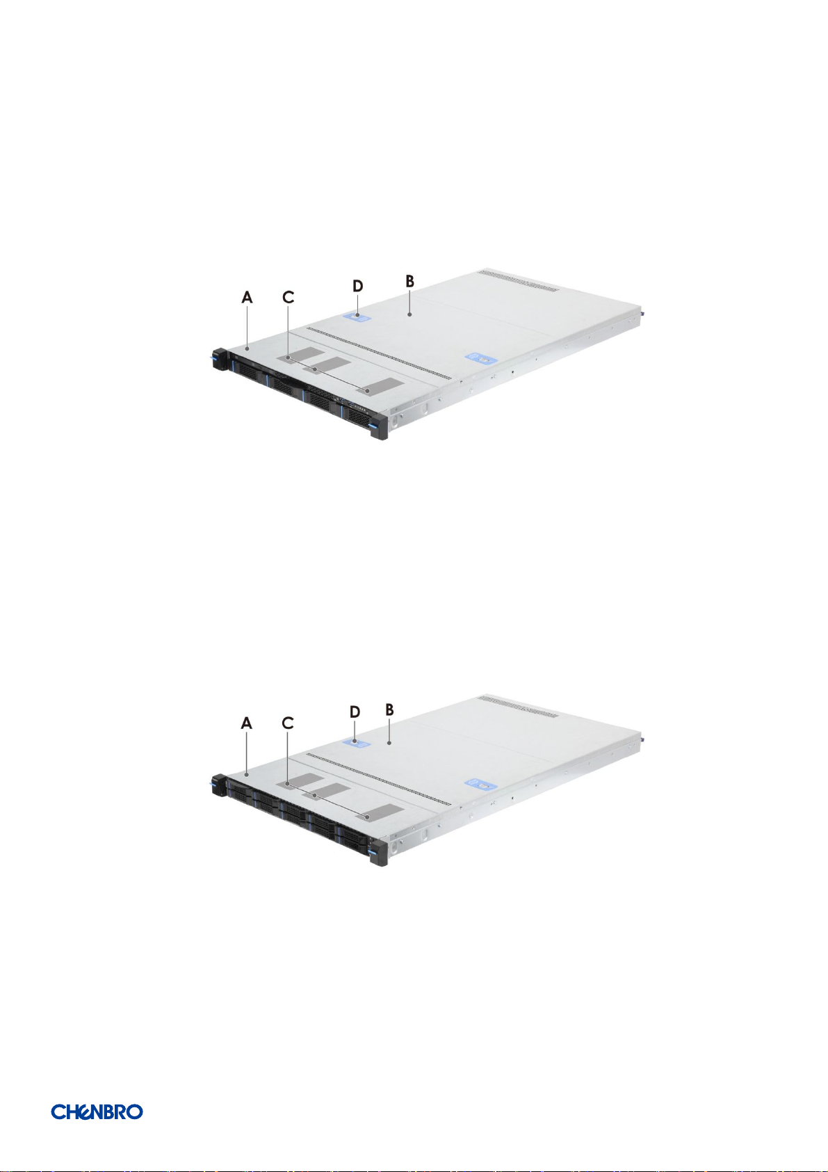
Figure 1 RM13804 overview
Figure 2 RM13810 overview
Product Overview │ 8
Page 9
RM138 Series
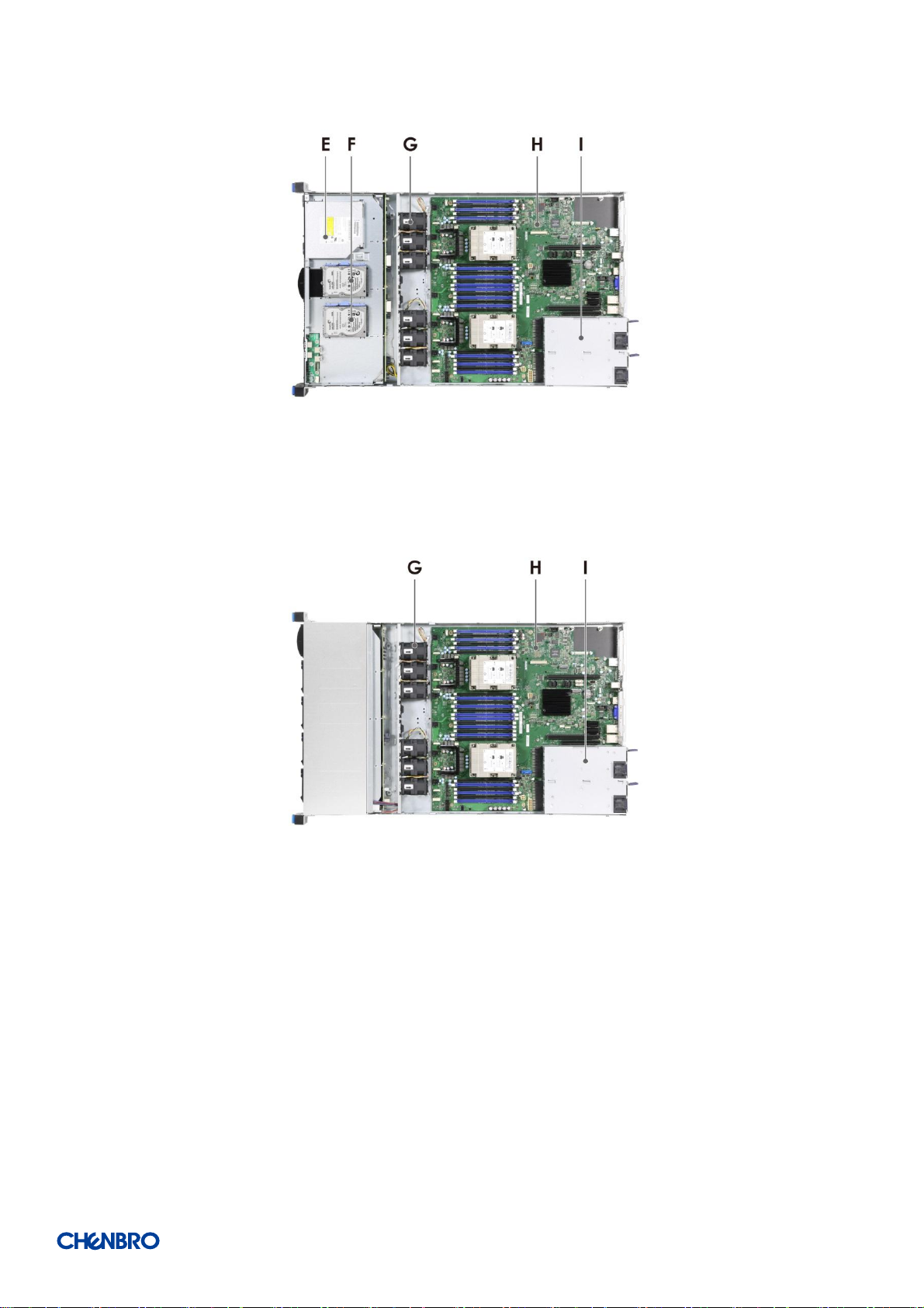
Figure 3 RM13804 major components overview
A. Front Top Cover
B. Rear Top Cover
C. Label Embossment
Figure 4 RM13810 major components overview
D. Rear Top Cover Latch
E. Optical Drive Bay
F. Internal 2.5” HDD Bays
G. Fan Assembly
H. Server Board
I. Power Supply
Product Overview │ 9
Page 10
1-2 Front Panel
RM138 Series
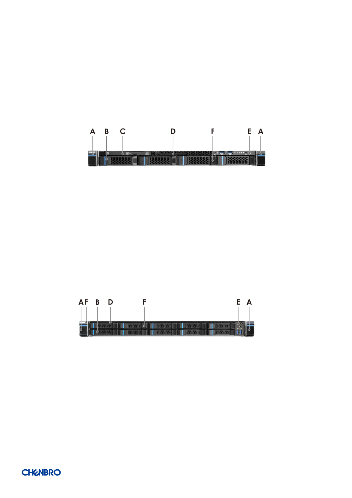
Figure 5 RM13804 front panel
A. Rack Handles
B. Storage Drive Bay
Figure 6 RM13810 front panel
C. Optical Drive Bay
D. Info Tag
E. Front Control Panel
F. Storage Drive Bay
Product Overview │ 10
Page 11
1-3 Back Panel
RM138 Series
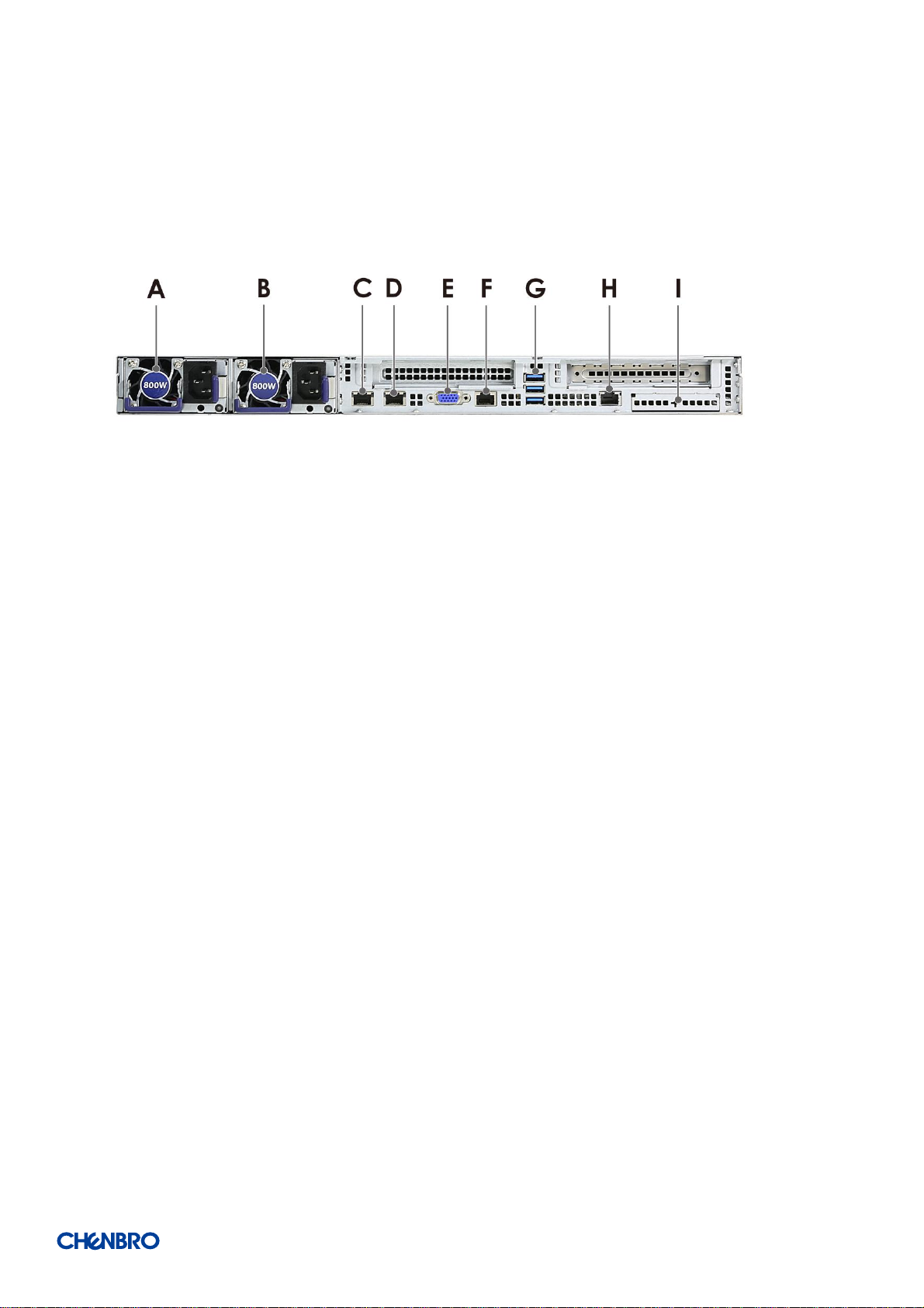
Figure 7 Back panel with redundant PSU
A. Power Supply #1
B. Power Supply #2
G. Stacked USB 2.0/3.0 Ports H. Remote Management I. Intel I/O Module Bay
C. NIC 1 (RJ45)
D. NIC 2 (RJ45)
E. Video Port (VGA)
F. Serial Port A (RJ45)
Product Overview │ 11
Page 12
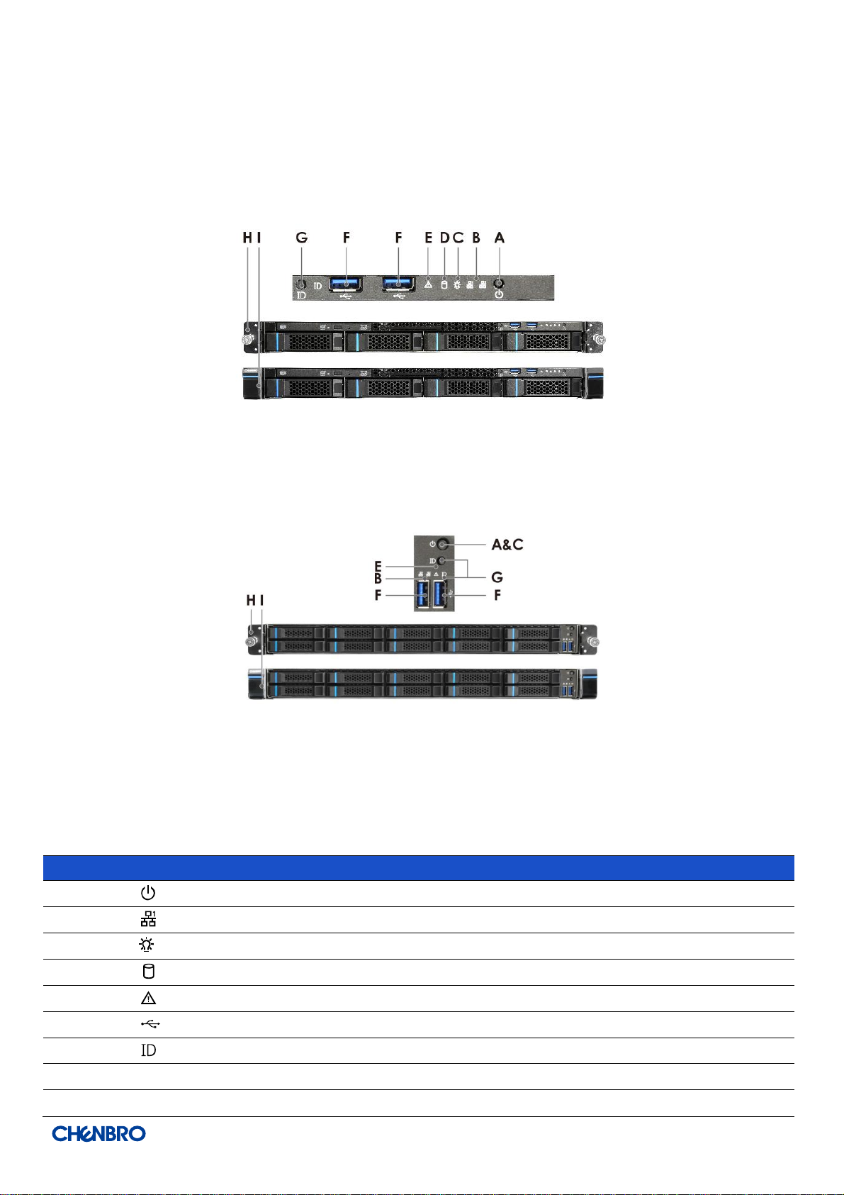
Label
ICON
Indicator, button, or connector
A
Power Button
B
LAN1, LAN2 Activity LED
C
Power LED
D
HDD Activity LED
E
System Alarm LED
F
USB 3.0
G
UID Button/LED
H
Rack Handle (Screw Type, Option )
I
Rack Handle (Latch Type)
1-4 Front Control Panel
RM138 Series
Figure 8 Front control panel
Figure 9 Front control panel
Table 2 Front control panel
Product Overview │ 12
Page 13
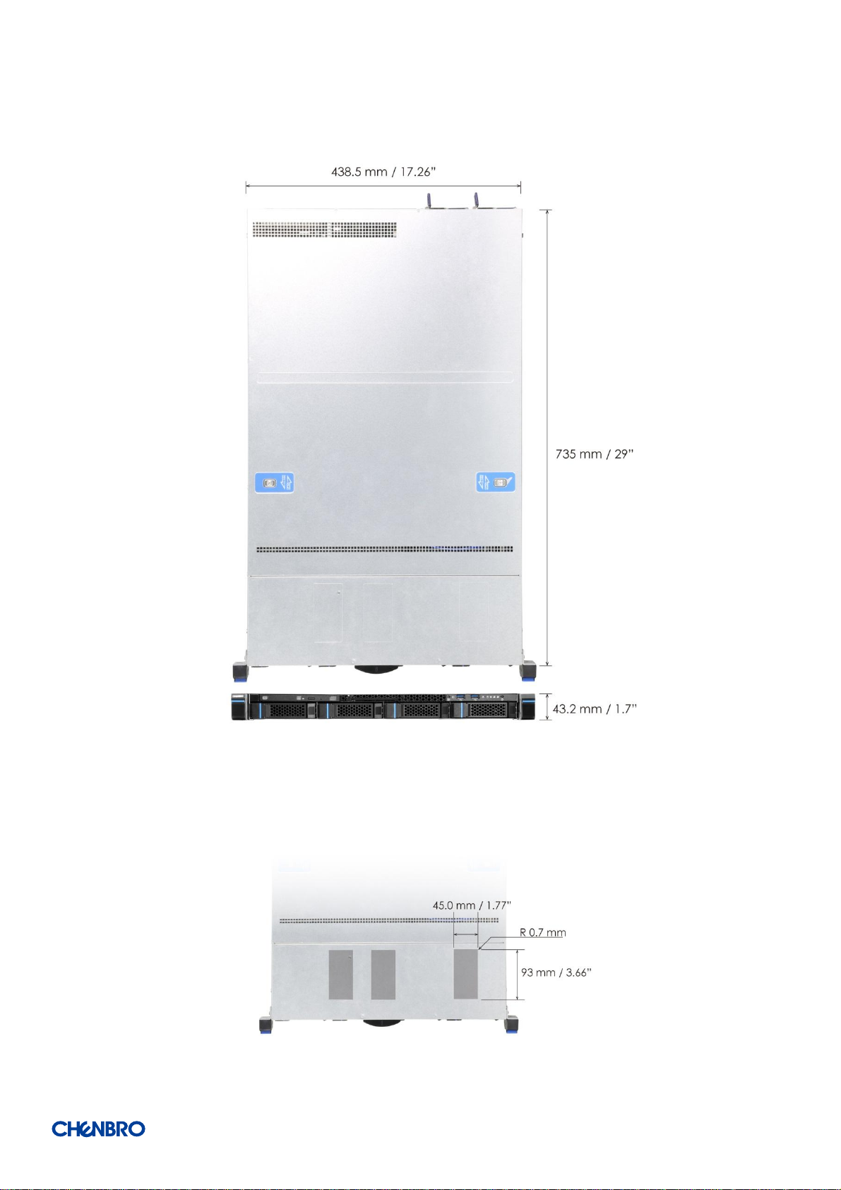
1-5 Chassis Dimensions
RM138 Series
Figure 10 Chassis dimensions
Figure 11 Label emboss dimensions
Product Overview │ 13
Page 14

RM138 Series
Part Number
384-23803-3300B0
84H314610-003
Rail Dimension (mm/inch)
835/32.9"
599/23.6"
Applicable Cabinet-
Post to Post (mm/inch)
668~936 / 26.3"~36.9"
660~838 / 26"~33"
3 Section/2 Section
3 Section
2 Section
Traveling Distance (mm/inch)
782/30.8"
560/22.0"
Support Chassis Width (mm)
438
438.5
Loading (kg)
30.8kg
18.8kg
Max. Static Loading (kg) for UL
100kg
60kg
Tool-less
Yes
Yes
Support CMA
Yes
No
1-6 Available Rack Mounting Kit Options (Refer to “Installation”)
Advisory Note – Available rack and cabinet mounting kits are not designed to support shipment of the server system while installed
in a rack. If you chose to do so, Chenbro advises you to verify your shipping configuration with appropriate shock and vibration
testing, before shipment. Chenbro does not perform shipping tests which cover the complex combination of unique rack offerings
and custom packaging options.
Caution: Exceeding the specified maximum weight limit of a given rail kit or misalignment of the server in the rack may result in
failure of the rack rails, causing damage to the system or personal injury. Two persons to operate or the use of a mechanical assist
tool to install and align the server into the rack is highly recommended.
Available rack mounting kits:
Table 3 Slide rail options
Product Overview │ 14
Page 15

Parameter
Specification
Temperature
Operating
5º C to 35º C (41º F to 95º F)
Temperature
Non-Operating
-40º C to 70º C (-40º F to 158º F)
Humidity
Non-Operating
50% to 90%, non-condensing with a maximum wet bulb of 28° C (at
temperatures from 25° C to 35° C)
Unpackaged
Shock
Non-Operating
Trapezoidal, 25 g, velocity change is based on product weight
Unpackaged
Vibration
Operating
5 Hz @ 0.0002 g2/Hz to 350 Hz @ 0.0002 g2/Hz
Input acceleration is 0.26 g RMS
10 minutes per axis for all 3 axes on all samples
Random control limit tolerance is ± 3 dB
Sag & bow
Non-Operating
Tolerance analysis among rack, rail and chassis
Actual on rack test with EIA Go-NoGo fixture
EMI
Pre-scan
Radiated Emissions
CISPR CLASS A (under 6dB):
30~1000 MHz vertical/horizontal
1G~6G GHz vertical/ horizontal
1G~18G GHz vertical/horizontal
ESD
Contact and Air Discharge
Electrostatic Discharge Immunity Test IEC 61000-4-2
RVI
Operating
HDD class:
Class 1: Highest performance, reliability, and data integrity
Class 2: A second tier of performance, reliability, and data integrity
HDD I/O throughput degradation SPEC
Pass/Fail Criteria:
No functional failure during test or post-test diagnostics.
Requirement to pass test is based on IOMeter data throughput (in IO’s per
second) expressed as a percent of Test HDD maximum theoretical
baseline performance
Class1: > 90% of baseline for 4K random writes and > 80% of baseline for
128K sequential writes.
Class2: > 85% of baseline for 4K random writes and > 75% of baseline for
128K sequential writes.
Mix: > 80% of baseline for 4K random writes and > 70% of baseline for
128K sequential writes.
Packaged
Vibration
Non-Operating
ISTA (weight over 68 kg, 1B ; weight equal or less than 68 kg, 1A)
Packaged
Drop
Non-Operating
Drop height change is based on product weight
Non-palletized product:
Investigation: Test requirement is 6 face drops, 8 corner drops and 12
edge drops for a total of 26 drops.
Validation: Test requirement is 6 face drops, 2 corner drops and 3 edge
drops for a total of 11 drops.
Palletized product: (Both investigation and validation)
Perform two bottom drops at the specified height, 10 bottom drops at
one half of the specified height.
Perform 4 rotational edge drops (one per edge) at the specified height.
1-7 System Level Environmental Specifications
The following table defines the system level specifications under operating and non-operating environments.
Table 4 System environmental specifications summary
RM138 Series
Product Overview │ 15
Page 16

RM138 Series
Part Number
Single/ Bulk
Form factor (mm)
Support level
387-13804-3102A0
Single
920 x 595 x 180
L5
Product
Unpackaged Net Weight
(kg)
Packaged Gross Weight
(kg)
Unpackaged Net Weight
(lbs)
Packaged Gross Weight
(lbs)
RM13804
11.6
15.3
25.6
33.7
RM13810
11.6
15.3
25.6
33.7
1-8 System Packaging
The original Chenbro packaging, where the server system is delivered, is designed to provide protection for L5 configuration and
tested to meet ISTA (International Safe Transit Association) Test Procedure 1A (2008). The packaging is also designed to be reused
for shipment after the system integration has been completed.
The original packaging includes the shipping box, and various protective inner packaging components, which are designed to
function together as a protective packaging system. When reused, all of the original packaging material must be used, including box
and each inner packaging component. In addition, all inner packaging components MUST be reinstalled in the proper location to
ensure adequate protection of the system for subsequent shipment.
Table 5 Syst em packaging information
NOTE: The design of the inner packaging components does not prevent improper placement within the packaging assembly.
There is only one correct packaging assembly that will allow the package to meet the ISTA (International Safe Transit
Association) Test Procedure 1A (2008).
Failure to follow the specified packaging assembly instructions may result in damage to the system during shipment.
Table 6 Product weight information
NOTE: A L5 system does not include M/B, processors, memory, drives, or add-in cards. It is the system configuration as
shipped from Chenbro. Weights of integrated system (system configurations that include the items above) will vary
depending on the final system configuration. For the 1U product, a fully integrated un-packaged system can weigh up to 40
Lbs. (18+ Kg).
Product Overview │ 16
Page 17

RM138 Series
2. System Components Removal and Installation
RM13804/10 supports for a variety of different storage options:
Up to 4 x 3.5” hot swap SAS / SATA HDD (RM13804)
Up to 10 x 2.5” hot swap SAS / SATA HDD or SSD (RM13810)
2 x 2.5’’ internal HDD or SSD up to 9.5mm thickness (RM13804)
Support for different storage and peripheral options will vary depending on the system model and/or available accessory options
installed.
BEFORE YOU BEGIN
WARNING: Watch out Safety and ESD precautions instruction before installing the server.
/System Components Removal and Installation │ 17
Page 18

2-1 Top Cover Removal and Installation
RM138 Series
Figure 12 Rear top cover removal
1. Loosen 2 screws as shown.
2. Press and hold 2 buttons, and slide the rear top cover toward the back of chassis base.
Figure 13 Front top cover removal
1. Loosen 2 screws as shown.
2. Slide the front top cover toward the back of chassis base, and remove it vertically.
/System Components Removal and Installation │ 18
Page 19

RM138 Series
Figure 14 Front top cover installation
1. Align the guide pins of this cover with the grooves on the chassis base, and slide the cover in toward the front panel.
(2 guide pins for both sides)
NOTE: Ensure that arrows on the cover indicating the back of the chassis.
2. Secure it with 2 screws as shown.
Figure 15 Rear top cover installation
1. Align the guide pins of the rear top cover with the grooves on the chassis base, and slide this cover toward the front panel until it
clicks. (4 guide pins for both sides)
Note: Ensure the 2 buttons are in position.
2. Secure it with 2 screws as shown.
/System Components Removal and Installation │ 19
Page 20

2-2 HDD Cage Removal and Installation
RM138 Series
Figure 16 RM13804 HDD cage removal
1. Loosen 2 screws of the chassis base as shown.
2. Pull the HDD cage toward the front panel until it unlocks.
3. Remove the HDD cage vertically.
Figure 17 RM13804 HDD cage installation
1. Align the guide pins on the chassis base with the grooves on the HDD cage as shown, and push HDD cage backward the front
panel until it locks.
2. Secure HDD cage with 2 screws as shown.
/System Components Removal and Installation │ 20
Page 21

RM138 Series
Figure 18 RM13810 HDD cage removal
1. Loosen 2 screws of the chassis base as shown.
2. Pull the HDD cage toward the front panel until it unlocks.
3. Remove the HDD cage vertically.
Figure 19 RM13810 HDD cage installation
1. Align the guide pins on the chassis base with the grooves on the HDD cage as shown, and push HDD cage backward the front
panel until it locks.
2. Secure HDD cage with 2 screws as shown.
NOTE: All cage SKUs follow the same removal and installation guidelines.
/System Components Removal and Installation │ 21
Page 22

2-3 Hot-swap HDD Assembly Removal and Instruction
RM138 Series
Figure 20 3.5” hot-swap HDD assembly removal
1. Press the tray button, and release the lever as shown.
2. Pull the HDD assembly out of the drive bay.
Figure 21 3.5” hot-swap HDD assembly installation
1. With the open lever, insert the HDD assembly into the drive bay until the end of the HDD cage.
2. Push in the lever when it is secured with a click.
/System Components Removal and Installation │ 22
Page 23

RM138 Series
Figure 22 3.5” HDD removal (tool-less)
1. Loosen a screw as shown and bottom up the HDD tray, and face the wider side of HDD tray as shown.
2. Press your 2 thumbs on the HDD as shown
NOTE: Please operate this on a stable surface in case the HDD dropping unexpectedly.
3. Lift the narrower side with your other fingers and release the HDD.
Figure 23 3.5” HDD installation (tool-less)
1. Slide in the HDD until align the anchor point of HDD tray.
2. Push down the HDD when it is locked with a click.
/System Components Removal and Installation │ 23
Page 24

RM138 Series
Figure 24 3.5” HDD removal (screw)
1. Loosen 4 screws as shown.
2. Take out the HDD from the tray.
Figure 25 3.5” HDD installation (screw)
1. Align the HDD with the anchor point on the tray.
2. Fasten the tray with 4 screws as shown.
/System Components Removal and Installation │ 24
Page 25

RM138 Series
Figure 26 2.5” HDD removal in 3.5” tray (screw)
1. Loosen 3 screws as shown.
2. Remove the HDD.
Figure 27 2.5” HDD installation in 3.5” tray (screw)
1. Install the HDD in position on the tray.
2. Secure 3 screws as shown.
/System Components Removal and Installation │ 25
Page 26

Figure 28 2.5’’ hot-swap HDD assembly removal
1. Press the tray button, and release the lever as shown.
2. Pull in the HDD assembly out of the drive bay chassis.
RM138 Series
Figure 29 2.5’’ hot-swap HDD assembly installation
1. With the open lever, insert the HDD assembly into the drive bay until the end of the HDD cage.
2. Push in the lever when it is secured with a click.
/System Components Removal and Installation │ 26
Page 27

RM138 Series
Figure 30 2.5’’ HDD removal (tool-less)
1. Bottom up the HDD tray, and face the side without a concave slot of HDD tray as shown.
2. Press your 2 thumbs on the HDD as shown.
NOTE: Please operate this on a stable surface in case the HDD dropping unexpectedly.
3. Lift the side with a concave slot by your other fingers and release the HDD.
Figure 31 2.5” HDD installation (tool-less)
1. Slide in the HDD until align the anchor point of HDD tray.
2. Push down the HDD when it is secured with a click.
/System Components Removal and Installation │ 27
Page 28

RM138 Series
Figure 32 2.5’’ HDD removal (screw)
1. Loosen 4 screws as shown.
2. Take out the HDD from the tray.
Figure 33 2.5” HDD installation (screw)
1. Align front HDD with the anchor points on the tray.
2. Assemble 2.5” HDD with tray by 4 screws on the side of tray.
/System Components Removal and Installation │ 28
Page 29

2-4 Internal 2.5” ODD Removal and Installation
RM138 Series
Figure 34 Internal 2.5'' HDD removal (RM13804)
1. Lift the plastic bracket tab to release HDD assembly as shown.
2. Remove it from the HDD cage.
3. Detach the plastic bracket from HDD.
Figure 35 Internal 2.5'' HDD installation (RM13804)
1. Attach the plastic bracket with HDD by engaging 4 pins with the dimples on one side of HDD.
2. Align the 2 dimples of the other side of HDD with the 2 hooks on the HDD cage as shown.
3. Push down the side with plastic bracket of HDD assembly until it is secured with a click.
/System Components Removal and Installation │ 29
Page 30

2-5 Slim ODD Removal and Installation
RM138 Series
Figure 36 Slim ODD removal (RM13804)
1. Lift the side of ODD to release it as shown.
2. Take out the ODD from the cage..
Figure 37 Slim ODD installation (RM13804)
1. Align 2 dimples on the ODD with 2 hooks on the cage, and slide the ODD in as shown.
2. Push the ODD down until it is secured with a click.
/System Components Removal and Installation │ 30
Page 31

2-6 System Maintenance
Figure 38 Removal of whole system from the rack (screw type)
RM138 Series
1. Loosen 2 the thumb screws anti-clockwise.
2. Firmly grab the rack handles on both sides, and pull it out of the rack with 2 hands.
Figure 39 Installation of whole system into the rack (screw type)
1. Firmly hold the system on both with 2 hands, and push the system all the way into the cabinet.
2. Secure it with 2 thumb screws clockwise on both sides as shown.
/System Components Removal and Installation │ 31
Page 32

RM138 Series
Figure 40 Removal of whole system from the rack (latch type, OTS)
1. Open and hold the latches on both sides as shown.
2. Loosen the screws in the latches as shown, and firmly grab the rack handles on both sides.
3. Pull it out of the rack with 2 hands.
Figure 41 Installation of whole system into the rack (latch type, OTS)
1. Firmly hold the system on both sides with 2 hands, and push the system all the way into the cabinet.
2. Open and hold the latches on both sides as shown.
3. Tighten the screws in the latches on both sides.
/System Components Removal and Installation │ 32
Page 33

2-7 Fan Assembly Removal and Installation
RM138 Series
Figure 42 Fan module removal (4028)
1. Detach the rivets on the fan module with the grooves of the chassis base.
2. Loosen 4 screws as shown to release the fan bracket from the chassis base.
Figure 43 Fan assembly removal (4028)
1. Detach 4 rivets from the fan as shown.
2. Loosen 2 screws to release the fan guard.
/System Components Removal and Installation │ 33
Page 34

RM138 Series
Figure 44 Fan assembly installation (4028)
1. Attach the fan guard with fan as shown and secure it with 2 screws.
2. Insert 4 rivets with the fan as shown.
Figure 45 Fan module installation (4028)
1. Attach the fan bracket with the chassis base as shown and secure it with 4 screws.
2. Insert and align the rivets on the fan module with the grooves of the chassis base, and ensure them engaged.
/System Components Removal and Installation │ 34
Page 35

Figure 46 Fan module removal (4048)
1. Detach the rivets on the fan module with the grooves of the chassis base.
RM138 Series
2. Loosen 4 screws as shown to release the fan bracket from the chassis base.
Figure 47 Fan assembly removal (4048)
1. Detach 4 rivets from the fan as shown.
2. Loosen 2 screws to release the fan guard.
3. Detach the plastic extension holder with fan.
/System Components Removal and Installation │ 35
Page 36

Figure 48 Fan assembly installation (4048)
1. Attach the fan guard with fan as shown and secure it with 2 screws.
RM138 Series
2. Attach the plastic extension holder with fan.
3. Insert 4 rivets with the fan as shown.
Figure 49 Fan module installation (4048)
1. Attach the fan bracket with the chassis base as shown and secure it with 4 screws.
2. Insert the and align the rivets on the fan module with the grooves of the chassis base, and ensure them engaded.
/System Components Removal and Installation │ 36
Page 37

Figure 50 Fan module removal (4056)
1. Detach the rivets on the fan module with the grooves of the chassis base.
RM138 Series
2. Loosen 4 screws as shown to release the fan bracket from the chassis base.
Figure 51 Fan assembly removal (4056)
1. Detach 4 rivets from the fan as show.
2. Loosen 2 screws to release the fan guards.
/System Components Removal and Installation │ 37
Page 38

Figure 52 Fan assembly installation (4056)
1. Attach the fan guard with fan as shown and secure it with 2 screws.
RM138 Series
2. Insert 4 rivets with the fan as shown.
Figure 53 Fan module installation (4056)
1. Attach the fan bracket with the chassis base as shown and secure it with 4 screws.
2. Insert and align the rivets on the fan module with the grooves of the chassis base, and ensure them engaged.
/System Components Removal and Installation │ 38
Page 39

RM138 Series
Figure 54 Air baffle removal
1. Remove the air baffle vertically from the chassis base.
Figure 55 Air baffle installation
1. Insert the air baffle into the securing slot until it is locked.
/System Components Removal and Installation │ 39
Page 40

2-8 PCI-e Card Installation
RM138 Series
Figure 56 PCI-e card blank removal
1. Remove the PCI-e blank as shown.
Figure 57 PCI-e card installation
2. Secure the riser card with PCI-e bracket by 2 screws.
3. Align 2 screw holes of PCI-e slot bracket with the PCI-e card as shown, and secure them with 2 screws.
4. Insert the PCI-e card into the slot on the riser card.
5. Insert the riser card into the M/B expansion Slot 2.
.
/System Components Removal and Installation │ 40
Page 41

2-9 PSU Installation and Removal
RM138 Series
Figure 58 1U single PSU installation-1
Figure 59 1U single PSU installation-2
1.
/System Components Removal and Installation │ 41
Page 42

RM138 Series
Figure 60 1U Redundant PSU module installation
1. Insert the PSU module into the PSU cage and push until it is secured with a click.
Figure 61 1U Redundant PSU module removal
1. Press and hole the latch as shown.
2. Pull the module handle to remove it from the cage.
/System Components Removal and Installation │ 42
Page 43

2-10 Slide Rail Installation
RM138 Series
Figure 62 Slide rail installation-1 (84H314610-003)
1. Attach the inner rail to the chassis base while aligning T pins on the side of the system with the slots on inner rail.
Figure 63 Slide rail installation-2 (84H314610-003)
2. Engage T pins with the slots on the inner rail.
/System Components Removal and Installation │ 43
Page 44

3. Lift the latch as shown.
RM138 Series
Figure 64 Slide rail installation-3 (84H314610-003)
4. Secure the inner rail with 1 screw.
Figure 65 Slide rail installation-4 (84H314610-003)
5. Install the system into the rack with 2 hands.
/System Components Removal and Installation │ 44
Page 45

RM138 Series
LED
ICON
LED
Color
Behavior
Condition
A,C Power LED
N/A
Stay off
Fault
Blue
Solid on
Present
B,D Activity LED
Green
Stay on
Access
Red
Solid on
Failure
1Hz blink
Rebuild
4Hz blink
Locate
3. Backplane
Each drive carrier includes two LED indicators for drive activity and drive status. Light pipes integrated into the drive tray direct light
emitted from LEDs mounted next to each drive connector on the backplane to the drive tray faceplate, making them visible from the
front of the system.
Figure 66 Drive tray LED identification
Table 7 Drive power LED/activity LED behavior
NOTE: The drive activity LED is driven by signals coming from the drive itself. Drive vendors may choose to operate the activity
LED different from what is described in the table above. Should the activity LED on a given drive type behave differently than
what is described, customers should take the drive vendor specifications as a reference for the specific drive model to
determine what the expected drive activity LED operation should be.
/ Backplane │ 45
Page 46

RM138 Series
3-1 Storage Backplane Options
RM138 s upports below backplane s:
4 x 3.5” SATA 7-pin port to port passive backplane
10 x 2.5” Mini SAS HD passive backplane
10x 2.5” NVMe passive backplane
All available SAS/SATA/NVMe backplanes include the following common features:
12Gb/s SAS, 6Gb/s SAS/SATA, and PCIe Gen3 x4 NVMe
SFF-8680 12Gb/s rated drive interface connectors, providing both power and I/O signals to attached devices
SFF-8639 PCIe Gen3 x4 rated drive interface connectors, providing both power and I/O signals to attached devices
Hot swap support for SAS/SATA/NVMe devices
I2C interface from a 4-pin connector for device status communication to the BMC over slave SMBus
LEDs to indicate drive activity and status for each attached device
/ Backplane │ 46
Page 47

Specification
Host Interface
SATA 7-pin
HDD Interface
SAS / SATA
Hot-Swap
Yes, allows users to replace devices on line
Display
LED indicates status
Power LED – Off (Fault / Non-present)
– Blue on (Present)
Access LED – Green on (HDD busy)
Error LED – Red on(When HDD error)
Environment Monitor
Temperature sensor (U2,U3)
Connectors
1. 4 x SFF-8680 *4
2. 4 x 7-pin SATA
3. 2 x IDE 4P power connectors for +5V/12V
4. 1 x I2C Connector
Dimension
426.6(L) x 26.8(W) x 2.4(H) mm
Material
FR4 2 layers
3-2 3.5” 4-Port 12Gb/s Passive Backplane
Table 8 Backplane specifications
RM138 Series
Figure 67 Backplane front view
A. HDD_0
C. HDD_2
B. HDD_1
D. HDD_3
/ Backplane │ 47
Page 48

RM138 Series
Label
Description
Description
Drawing
A
Power
The backplane includes two 1x4 connector
supplying power to the backplane. Power is routed
to the backplane via a power cable harness from the
power supply .
B
SATA 7-pin
The backplane includes four SATA 7-pin connectors
providing data signals for four SAS/SATA drives on
the backplane. A cable can be routed from matching
connectors on the server board or add-in SAS/SATA
RAID cards.
C
I2C
The backplane includes a 1x4 connector used as a
management interface to the server board.
Figure 68 Backplane rear view
Table 9 Connector and pin header function description
/ Backplane │ 48
Page 49

Specification
Host Interface
Mini SAS HD
HDD Interface
SAS / SATA
Hot-Swap
Yes, allows users to replace storage devices on line
Display
LED indicates storage device status
Power LED – Blue on (HDD Present)
Access LED – Green on (HDD Busy)
Error LED – Red on (HDD Error)
Environment Monitor
Temperature sensor (U3)
Connectors
1. 10 x SFF-8680
2. 3 x Mini-SAS HD
3. 1 x ATX Mini Fit 4P Power connector for +12V only
4. 1 x I2C Connector
Dimension
405.0(L) x 33.3(W) x 2.4(H) mm
Material
FR4 6 layers
3-3 2.5” 10-Port 12Gb/s Passive Backplane
Table 10 Backplane specifications
RM138 Series
Figure 69 Backplane front view
A. HDD_0
B. HDD_1
C. HDD_2
D. HDD_3
E. HDD_4
F. HDD_5
G. HDD_6
H. HDD_7
I. HDD_8
J. HDD_9
/ Backplane │ 49
Page 50

RM138 Series
Label
Description
Description
Drawing
A
Power
The backplane includes one 2x2 connector
supplying power to the backplane. Power is routed
to the backplane via a power cable harness from the
power supply.
B
Mini-SAS HD
The backplane includes three multi-port mini-SAS
HD cable connectors providing data signals for ten
SAS/SATA drives on the backplane. A cable can be
routed from matching connectors on the server
board or add-in SAS/SATA RAID cards.
C
I2C
The backplane includes one 1 x 4 connector used as
a management interface to the server board.
Figure 70 Backplane rear view
Table 11 Connector and pin header function description
/ Backplane │ 50
Page 51

Specification
Host Interface
OCuLink
HDD Interface
NVMe
Hot-Swap
Yes, allows users to replace devices on line
Display
LED indicates storage device status
Power LED – Blue on (HDD Present)
Access LED – Green on (HDD Busy)
Error LED – Red on (HDD Error)
Environment Monitor
Temperature sensor (U3)
Connectors
1. 10 x SFF-8639
2. 10 x OCuLink
3. 2 x SATA 7-pin
4. 2 x ATX Mini Fit 4P Power connector for +12V only
5. 1 x I2C Connector
Dimension
405.0(L) x 37.33(W) x 2.4(H) mm
Material
FR4 8 layers
3.4 2.5” 10-Port NVMe Passive Backplane
Table 12 Backplane specifications
RM138 Series
Figure 71 Backplane front view
A. HDD_0
B. HDD_1
C. HDD_2
D. HDD_3
E. HDD_4
F. HDD_5
G. HDD_6
H. HDD_7
I. HDD_8
J. HDD_9
/ Backplane │ 51
Page 52

RM138 Series
Label
Description
Description
Drawing
A
Power
The backplane includes one 2 x 2 connector
supplying power to the backplane. Power is routed
to the backplane via a power cable harness from the
power supply.
B
OCuLink
The backplane includes ten OCuLink connectors
providing data signals for ten NVMe drives on the
backplane. A cable can be routed from matching
connectors on the server board or add-in PCIe
switch cards.
C
I2C
The backplane includes one 1 x 4 cable connector
used as a management interface to the server
board.
D
SATA 7-pin
The backplane includes two SATA 7-pin connectors
providing data signals for two SAS/SATA drives on
the backplane. A cable can be routed from matching
connectors on the server board or add-in SAS/SATA
RAID cards.
Figure 72 Backplane rear view
Table 13 Connector and pin header function description
/ Backplane │ 52
Page 53

RM138 Series
CENBRO MICOM CO., LTD.
Email: fae@chenbro.com
Tel: +886-2-82265500
Fax: +886-2-82265392
CHENBRO MICOM (USA) INC.
Email: usfae@chenbro.com
Tel: +1-909-947-3200
Fax: +1-909-947-4300
CHENBRO GmbH
Email: defae@chenbro.com
Tel: + 49-2154-8142730
Apply a RMA
number
Return the product for
repair
Receive service
charge notice
Receive the repaired
product
4. Maintenance and Service
DOA (Dead on Arrival)
If the products are found Defect On Arrival, please contact Chenbro’s regional sales or CQE and indicate the defective status via
email along with product photos and description. You may need to return the defective item by request.
The customer should ensure that the products are Defect On Arrival for up to three months from Chenbro’s shipping date and the
damage is not caused by shipping or failures resulting from accident, misuse, abuse, neglect, mishandling, misapplication,
modification, improper operation, improper repair or rework. CHENBRO is not responsible for the cost of replacement including the
delivery cost.
CHENBRO also reserves the right to examine the DOA products. If the damage of DOA products is caused by improper action as
described above, the customer will be liable for paying the related charge having occurred or paying the fee of the replacements if
the DOA products are totally scrapped.
TECHNICAL SUPPORT
Please provide following information when you apply our technical support:
Product model name and/or part number
Product serial number and bar code
Buzzer beeping pattern and/or failure LED flashing pattern
Detailed, specific questions
You may also contact Chenbro’s regional technical supports as below- Website: www.chenbro.com
/ Maintenance and Service │ 53
 Loading...