

Page 1

Chenbro Storage Chassis
1
8-Port 12Gbps Mini-SAS HD Backplane User Manual
8-port 12Gpbs Mini-SAS HD Backplane
User Manual
Published: February 2016
Version: 1.0
Http://www.chenbro.com
Page 2

Chenbro Storage Chassis
2
8-Port 12Gbps Mini-SAS HD Backplane User Manual
Copyright
Copyright © 2006 Chenbro Micom Co., Ltd.. All rights reserved.
Unless otherwise indicated, all materials in this manual are copyrighted by Chenbro Micom Co., Ltd.. All
rights reserved. No part of this manual, either text or image may be used for any purpose other than internal
use within purchasing company. Therefore, reproduction, modification in any form or by any means,
electronic, mechanical or otherwise, for reasons other than internal use, is strictly prohibited without prior
written permission.
Chenbro Micom Co., Ltd. reserves the right to make improvement and modification to the products
indicated in this manual at any time. Specifications are therefore subject to change without prior notice.
Information provided in this manual is intended to be accurate and reliable. However, Chenbro Micom Co.,
Ltd., assumes no responsibility for its use, nor for any infringements upon the rights of third parties, which
may result from its use.
Technical Support
Chenbro works hard to offer our customers maximum performance from our chassis. But in case you have
any problem with our product you can find supports from the following resources.
Web Support
Detail information of our products is in our website. You can find technical updates, installation guides, FAQs,
technical specifications and more. Our web address is: www.chenbro.com.
Email Support
You can also fill out the technical support form at our Technical Support page. You technical issue inquiries
will be sent directly to our support professionals.
Phone Support
You can also contact Chenbro HQ or branch office for immediate support; contact Information is as
following:
Chenbro HQ Chenbro Europe B.V. Chenbro Beijing
Tel: 886-2-8226-5500 Tel: 31-40-295-2045 Tel: 86-10-8274-3036~ 39
Fax: 886-2-8226-5423 Fax: 31-40-295-2044 Fax: 8610-8274-3035
Chenbro Micom (USA) Inc.
Tel: 1-909-947-3200
Fax : 1-909-947-4300
Http://www.chenbro.com
Page 3

Chenbro Storage Chassis
3
8-Port 12Gbps Mini-SAS HD Backplane User Manual
Table of Content
Revision History .............................................................................................................. 4
Chapter 1 Introduction ................................................................................................. 5
Features ................................................................................................................................................................................................... 5
Connectors ............................................................................................................................................................................................. 5
Board and Environmental Characteristics .................................................................................................................................. 5
Connectors Location .......................................................................................................................................................................... 6
Chapter 2 Connectors .................................................................................................... 7
Power Connector: CN01, CN02, CN03, CN04 ........................................................................................................................... 7
Fan Connectors: JF01, JF02, JF03, JF04 ........................................................................................................................................ 7
Power fail alarm connector: JP0 ..................................................................................................................................................... 7
Power fail mute connector: JM1 .................................................................................................................................................... 8
Front LED board connector: CN3 .................................................................................................................................................. 8
I2C Connector: JC1 ............................................................................................................................................................................... 8
Mini SAS HD Connector: CB1, CB2 ............................................................................................................................................... 9
HDD Connector (CN011, CN021, CN031, CN041, CN051, CN061, CN071, CN081).................................................. 9
Chapter 3 Using the 80H10323606A0 backplane ............................................. 10
HDD Status indicators ...................................................................................................................................................................... 10
Wide port status indicators ........................................................................................................................................................... 10
DIP Switch ............................................................................................................................................................................................. 10
Buzzer Code ......................................................................................................................................................................................... 11
IPMI interface – I2C Address setting ........................................................................................................................................... 11
Chapter 4 Limited Warranty .................................................................................... 12
Purpose .................................................................................................................................................................................................. 12
SCOPE ..................................................................................................................................................................................................... 12
AUTHORITY .......................................................................................................................................................................................... 12
NOUN DEFINITION ........................................................................................................................................................................... 12
WARRANTY .......................................................................................................................................................................................... 12
DOA (DEFECT ON ARRIVAL) .......................................................................................................................................................... 13
REPAIR PROCESS ................................................................................................................................................................................ 13
Http://www.chenbro.com
Page 4
4
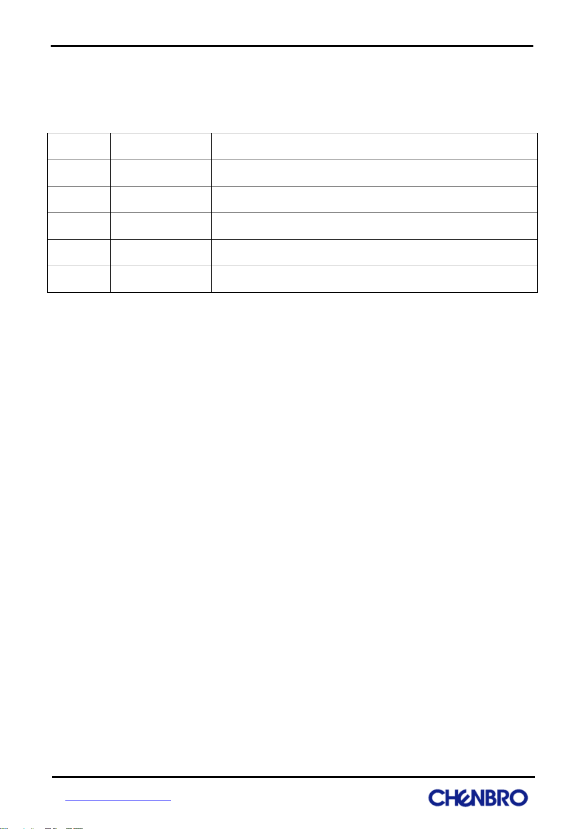
Revision
Date
Modifications
1.0
February/18/2011
First Release
Revision History
Chenbro Storage Chassis
8-Port 12Gbps Mini-SAS HD Backplane User Manual
Http://www.chenbro.com
Page 5

Chenbro Storage Chassis
5
8-Port 12Gbps Mini-SAS HD Backplane User Manual
Chapter 1 Introduction
This manual gives technical information needed to use the 80H10323606A0 (8port, 12Gbps) backplane,
which can fit into RM23608 model.
Features
Fit into RM23608 model.
Provide connector for standard power supply
Support HDD indicators for each hard drive.
Support Smart Fan Speed Control for energy saving.
Connectors
Refer to the section of Connectors Location for connector placement.
A. SFF-8482 HDD connector (29 pin) x 8 for SAS/SATA HDD connection
B. SFF-8643 Mini-SAS HD Connector for host connection x 2
C. Standard 4P Power connector x 4 for +5V and +12V from power supply
D. Pin Header 2.54mm (2x3) x 1 for front panel fail LED indicator and mute switch connection.
E. 2510 Wafer 2.54mm connector 4P x 4 for system fan connection
F. 2510 Wafer 2.54mm connector 2P x 2 for PSU TTL (Transistor-Transistor Logic) signal
G. Wafer 2.5mm connector 4P x 1 I
2
C connection, it’s used to link with motherboard BMC.
Board and Environmental Characteristics
Dimension 425.0mm x 54.7mm with thickness 2.4mm
6-Layer PCB
Http://www.chenbro.com
Page 6

6
I2C
TTL
FAN
Mini-SAS HD
Power Conn
Front Panel
HDD Conn
Connectors Location
Chenbro Storage Chassis
8-Port 12Gbps Mini-SAS HD Backplane User Manual
Http://www.chenbro.com
Page 7

Chenbro Storage Chassis
7
Pin Number
Pin Definition
Drawing
1
+12V
2
GND
3
GND
4
+5V
PIN-Number
PIN-Define
Drawing
1
GND
2
+12V
3
FAN Clock Input
4
FAN PWM Output
PIN-Number
PIN-Define
Drawing
1
GND
2
Fail Signal Input (Active Low)
8-Port 12Gbps Mini-SAS HD Backplane User Manual
Chapter 2 Connectors
Power Connector: CN01, CN02, CN03, CN04
The connectors allow to connect a standard 4-pin power connector to provide backplane power.
Fan Connectors: JF01, JF02, JF03, JF04
The 4pin fan connectors are used for system fan. There is a MCU on the backplane to provide smart fan
speed control for energy saving.
Power fail alarm connector: JP0
The connector is used to transfer power fail signal from PSU to backplane, backplane will turn on global fail
LED indicator at front LED panel when PSU fail, the cable can be found at the chassis PSU.
Http://www.chenbro.com
Page 8

Chenbro Storage Chassis
8
PIN-Number
PIN-Define
Drawing
1
Mute (-)
2
Mute (+)
PIN-Number
PIN-Define
Drawing
1
Fail LED (+)
2
Fail LED (-)
3
Key Pin
4
NC
5
Mute SW (+)
6
Mute SW (-)
PIN-Number
PIN-Define
Drawing
1
SDA
2
GND
3
SCL
4
+5V
8-Port 12Gbps Mini-SAS HD Backplane User Manual
Power fail mute connector: JM1
The connector is used to transfer mute signal from backplane to PSU. It provides mute function when PSU is
fail at front LED panel.
Front LED board connector: CN3
The backplane provides front LED board connector for fail LED indicator and mute switch at front LED
board.
I2C Connector: JC1
It’s used to link with motherboard BMC and backplane will provide monitoring information to BMC.
Http://www.chenbro.com
Page 9

Chenbro Storage Chassis
9
PIN-Number
PIN-Define
PIN-Number
PIN-Define
Drawing
A1
NA
C1
GND
A2
NA
C2
NA
A3
GND
C3
GND
A4
RP1
C4
TP1
A5
RN1
C5
TN1
A6
GND
C6
GND
A7
RP3
C7
TP3
A8
RN3
C8
TN3
A9
GND
C9
GND
B1
NA
D1
NC
B2
GND
D2
NA
B3
GND
D3
GND
B4
RP0
D4
TP1
B5
RN0
D5
TN1
B6
GND
D6
GND
B7
RP2
D7
TP2
B8
RN2
D8
TN2
B9
GND
D9
GND
PIN-Number
PIN-Define
PIN-Number
PIN-Define
Drawing
S1
GND
P1
NC
S2
RP
P2
NC
S3
RN
P3
NC
S4
GND
P4
GND
S5
TN
P5
POWER ENABLE
S6
TP
P6
GND
S7
GND
P7
5V PRE-CHARGE
S8
NC
P8
5V
S9
NC
P9
5V
S10
NC
P10
GND
S11
NC
P11
NC
S12
NC
P12
GND
S13
NC
P13
12V PRE-CHARGE
S14
NC
P14
12V
P15
12V
8-Port 12Gbps Mini-SAS HD Backplane User Manual
Mini SAS HD Connector: CB1, CB2
Mini SAS HD connectors are used to link with host or cascade to other active backplane. backplane will
automatically switch as downstream (cascade) or upstream (host) mode.
HDD Connector (CN011, CN021, CN031, CN041, CN051, CN061,
CN071, CN081)
It is used to connector with SAS/SATA HDD.
Http://www.chenbro.com
Page 10

Chenbro Storage Chassis
1
0
Status
Blue
Green
Red
No present
Off
Off
Off
Offline
On
Blink for HDD
activity /access
(InFrame) indicating
Off
Idle
On
Off
Active
On
Off
Fail
On
On
Locate
On
4Hz blink
Rebuild
On
1Hz blink
Status
Green
Red
Connected
Blink
OFF
Disconnected
OFF
ON
Function
DIP NO.
Default
ON
OFF
Fan 1
DIP1
On
Enable
Disable
Fan 2
DIP2
On
Enable
Disable
Fan 3
DIP3
On
Enable
Disable
Fan 4
DIP4
On
Enable
Disable
MB PWM
DIP5
On
Allows motherboard
control fan speed
Backplane control fan speed
Temp alarm
DIP6
On
Alarm at 55C
Alarm at 65C
ACC LED mode
DIP7
On
By SGPIO
By HDD PIN 11
Buzzer
DIP8
On
Enable
Disable
8-Port 12Gbps Mini-SAS HD Backplane User Manual
Chapter 3 Using the 80H10323606A0 backplane
HDD Status indicators
The HDD indicators provide the HDD status as following table
Wide port status indicators
The wide port indicators provide the wide port connection status of connected and disconnected.
DIP Switch
The DIP switch allows user to change system settings
※Refer to Buzzer Code
※Refer to I2C Address setting
Http://www.chenbro.com
Page 11

Chenbro Storage Chassis
1
1
Event
Tone
Fan alarm
One long beeps sound
Temperature alarm
Two short beeps sound
JP02
JP03
Address (8 bits)
JP1-2
JP1-2
0xC0
JP2-3
JP1-2
0xC4
JP1-2
JP2-3
0xC8
JP2-3
JP2-3
0xCC
8-Port 12Gbps Mini-SAS HD Backplane User Manual
Buzzer Code
Buzzer code allows user to identify the issue by the way it sound, user may disable the sound by ※DIP
switch
※Refer to DIP switch
IPMI interface – I2C Address setting
Backplane I2C address can be changed by jumper setting table as below, the default setting is 0xC0
Http://www.chenbro.com
Page 12

Chenbro Storage Chassis
1
2
8-Port 12Gbps Mini-SAS HD Backplane User Manual
Chapter 4 Limited Warranty
Purpose
CHENBRO has established its RMA guidelines to give customers the best support and shortest turn-around
time.
SCOPE
Sold products and parts by CHENBRO.
AUTHORITY
Customer Service Department
Leading and dealing with all QA/QC events.
Other Supporting Departments
Sales, PM, R/D, Electrical Validation, Logistical, etc., departments for technical or logistical support.
NOUN DEFINITION
Consumable parts/Custom products
Low value, general parts (such as plastic parts, cable, accessory kits), and metal parts.
Electronic parts
Power Supply, SCSI/IDE/SATA Backplanes, Riser Card, LED Board, Front USB PCB, etc.
WARRANTY
Warranty period
Consumable parts/Custom products problem responding time.
Electronic parts
Warranty period is from CHENBRO shipping date as followings:
Electronic parts for PC chassis (PC Series): One Year.
Electronic parts for Pedestal Server / Rack-mount chassis (SR/RM Series): Three Years.
Electronic parts for ES chassis (ES Series): Two Years.
Electronic parts for SK chassis (SK Series): Three Years.
Repairs under warranty
During the warranty period, CHENBRO will repair or replace all defective products.
Exclusions from warranty
The product is treated as exclusion from warranty if:
Http://www.chenbro.com
Page 13

Chenbro Storage Chassis
1
3
8-Port 12Gbps Mini-SAS HD Backplane User Manual
The product has been found to be defective after expiry of the warranty period.
The product has been subjected to abuse or unauthorized repair, accident or other cause. Such
conditions will be determined at CHENBRO discretion.
Products and accessories weren’t provided by CHENBRO
Product which is damaged beyond repair due to natural disasters
Consumable parts
DOA (DEFECT ON ARRIVAL)
If the products are found Defect On Arrival, please inform responsible CHENBRO Customer Service
Department of the defective status by e-mail with photo, bar code and description, if necessary, returning a
defected sample. Depending on the problem, QA/QC Department of CHENBRO should be responsible for
offering the best solution under mutual agreement. (e.g. replacement, rework, etc.)
The customer should ensure that the products are Defect On Arrival within three months from CHENBRO
shipping date and the damages are not caused by natural disasters, accident or improper operation.
CHENBRO is responsible for the cost of replacement including the delivery cost.
CHENBRO also reserves the right to examine the DOA products. If the products damaged by customer’s
improper action. The DOA products are totally discarded. The customer shall be liable for paying the related
charges occurred or paying the price for replacements.
REPAIR PROCESS
Obtaining a RMA number
When customer requests a RMA (Return Merchandise Authorization) number, please contact QA/QC
Department of CHENBRO and describes the problems encountered in detail and serial number/part number
on the “RMA Request Form”.
If customer is uncertain about the cause of the problem, please contacts QA/QC Department of CHENBRO.
They may be able to find a solution that does not require the product to be sent back for repair.
Returning the product for repairing
Please send the parts without accessories (manuals, cables, etc.). Remove any unnecessary parts from the
case, such as Motherboard, CPU or SDRAM. CHENBRO cannot be responsible for their return.
The customer will take care of the shipping charges. CHENBRO will take care of the returning charges. To
save handling time, the customer shall address the package directly to CHENBRO QA/QC Department.
List the value of the product on the invoice as zero (or a very low value). Otherwise, additional charges will
be levied by customs (which will be borne by the sender). CHENBRO suggest that customer writes “Goods
with no commercial value are returned for repair” on the shipment invoice.
The electronic parts through repaired. If there is same defect phenomenon within 3 months, the customer
possesses free charge service. The product still keeps original warranty period.
Service charges
CHENBRO will charge for repairing products if:
The product is repaired after expiry of the warranty period.
The product is tested after expiry of the warranty period and a No Defect Found (NDF) result is
obtained.
Http://www.chenbro.com
Page 14

Chenbro Storage Chassis
1
4
8-Port 12Gbps Mini-SAS HD Backplane User Manual
The product, though repaired within the warranty period, has been subjected to abuse or
unauthorized repair.
Product updates reworks and tests upon the request of customers.
Product is damaged beyond repair due to natural disasters.
NDF rate >= 10%, charge customer service/freight cost.
Before making the repairs, CHENBRO will send a “Failure Analysis Description” and a “Proforma Invoice” with
the repair charges to customer. When customer signs and returns then repairing products.
Repair Turn-around Time (TAT)
Electronic parts need repairing turn-around time 2 weeks and Power supply needs 3 weeks from CHENBRO
HQ receive the shipment till CHENBRO HQ ship out
The TAT may be delayed if the customer:
Does not sign and return the Proforma Invoice within 48 hours.
Fails to pay the Account Receive within the due date.
Gives an insufficient problem description, such as "does not work", "failure".
Has modified the original design of the CHENBRO product.
No repair/ No return
Does not sign and return the Performa Invoice within 48 hours.
Fails to pay the Account Receive within the due date.
Unclear failure description (written, screen shot etc.) provided by customer.
Attached accessories (manuals, cables, etc.) and unnecessary parts from the case
Repair service for phased-out products
CHENBRO offers a continuous repair service for one year after the date that product has been announced to
phase-out.
Http://www.chenbro.com
Page 15

Chenbro Storage Chassis
1
5
8-Port 12Gbps Mini-SAS HD Backplane User Manual
CHENBRO MICOM CO., LTD.
Our Website: www.chenbro.com
Http://www.chenbro.com
 Loading...