

Page 1

RM43596 JBOD
Rackmount Chassis User Manual
January 2019 Version 1.0
A document provides an overview of product features, functions, architecture, and support specifications
Page 2

RM43596 JBOD
<Table of Contents │ 2
DISCLAIMERS
No license (express or implied, by estoppel or otherwise) to any intellectual property rights is granted by this document.
Chenbro disclaims all express and implied warranties, including without limitation, the implied warranties of merchantability, fitness
for a particular purpose, and non-infringement, as well as any warranty arising from course of performance, course of dealing, or
usage in trade.
This document contains information on products, services and/or processes in development. All information provided here is subject
to change without notice. Contact your Chenbro representative to obtain the latest Configuration Guide.
The products and services described may contain defects or errors known as errata which may cause deviations from published
specifications. Current characterized errata are available on request.
Chenbro, and the Chenbro logo are trademarks of Chenbro Micom Co.,Ltd in the worldwide.
*Other names and brands may be claimed as the property of others
© 2019 Chenbro Micom Co.,Ltd.
Page 3

RM43596 JBOD
<Table of Contents │ 3
Table of Contents
Table of Contents ............................................................................................................................................... 3
List of Figures ..................................................................................................................................................... 4
List of Tables ....................................................................................................................................................... 5
1. Product Overview .............................................................................................................................. 6
1-1 System Features Overview ........................................................................................................... 7
1-2 Front Panel ................................................................................................................................... 8
1-3 Back Panel .................................................................................................................................... 9
1-4 Front Control Panel .................................................................................................................... 10
1-5 Chassis Dimensions .................................................................................................................... 11
1-6 Available Rack Mounting Kit Options (Refer to “Installation”) .................................................. 12
1-7 System Level Environmental Specifications ............................................................................... 13
1-8 System Packaging ...................................................................................................................... 14
2. System Components Removal and Installation ................................................................................ 15
2-1 Top Cover Removal and Installation .......................................................................................... 16
2-2 External Hot-Swap HDD Assembly Removal and Installation .................................................... 17
2-3 System Maintenance ................................................................................................................. 19
2-4 Fan Module Removal and Installation ....................................................................................... 20
2-5 Internal/External Expander Card Removal and Installation ...................................................... 24
2-6 PSU Removal and Installation .................................................................................................... 26
2-7 Slide Rail Installation .................................................................................................................. 27
3. Backplane ......................................................................................................................................... 29
3-1 Storage Backplane Options ........................................................................................................ 30
3-2 3.5” 24-Port 12Gb/s SATA/ SAS Passive Backplane (Front-Right/Front-Left) ............................. 31
3-3 3.5” 24-Port 12Gb/s SATA/SAS Passive Backplane (Rear-Right/Rear-Left) ................................ 33
4. Maintenance and Service................................................................................................................. 35
Page 4

RM43596 JBOD
List of Figures │ 4
List of Figures
Figure 1 Overview ........................................................................................................................................... 7
Figure 2 Overview ........................................................................................................................................... 7
Figure 3 Front panel ........................................................................................................................................ 8
Figure 4 Back panel overview ......................................................................................................................... 9
Figure 5 Front control panel ......................................................................................................................... 10
Figure 6 Chassis dimensions ......................................................................................................................... 11
Figure 7 Top cover installation ...................................................................................................................... 16
Figure 8 Top cover removal ........................................................................................................................... 16
Figure 9 3.5” hot-swap HDD assembly installation ....................................................................................... 17
Figure 10 3.5” hot-swap HDD assembly removal ......................................................................................... 17
Figure 11 3.5” HDD installation (tool-less type) ........................................................................................... 18
Figure 12 3.5” HDD removal (tool-less type) ................................................................................................ 18
Figure 13 Installation of whole system into the rack (tool-less type) .......................................................... 19
Figure 14 Removal of whole system from the rack (tool-less type) ............................................................. 19
Figure 15 Front fan module installation (8038) ............................................................................................ 20
Figure 16 Front fan module installation (8038) ............................................................................................ 20
Figure 17 Front fan module removal (8038) ................................................................................................. 21
Figure 18 Front fan module removal (8038) ................................................................................................. 21
Figure 19 Middle fan modules Installation (8038) ........................................................................................ 22
Figure 20 Middle fan modules removal (8038) ............................................................................................. 22
Figure 21 Rear fan modules installation (8038) ............................................................................................ 23
Figure 22 Rear fan modules removal (8038) ................................................................................................. 23
Figure 23 Internal expander card installation ............................................................................................... 24
Figure 24 Internal expander card removal .................................................................................................... 24
Figure 25 CRPS PSU installation .................................................................................................................... 26
Figure 26 CRPS PSU removal ......................................................................................................................... 26
Figure 27 Slide rail installation-1 (84H314610-003) ..................................................................................... 27
Figure 28 Slide rail installation-2 (84H314610-003) ..................................................................................... 27
Figure 29 Slide rail installation-3 (84H314610-003) ..................................................................................... 28
Figure 30 3.5” Drive tray/internal expander drive tray LED identification ................................................... 29
Figure 31 Backplane front view (front-right) ................................................................................................ 31
Figure 32 Backplane front view (front-left) .................................................................................................. 32
Figure 33 Backplane front view (rear-right) .................................................................................................. 33
Figure 34 Backplane front view (rear-left) .................................................................................................... 34
Page 5

RM43596 JBOD
List of Tables │ 5
List of Tables
Table 1 Chenbro RM43596 specifications ..................................................................................................... 6
Table 2 Front control panel ......................................................................................................................... 10
Table 3 Slide rail options ............................................................................................................................. 12
Table 4 System environmental specifications summary ............................................................................. 13
Table 5 System packaging information ...................................................................................................... 14
Table 6 Product weight information ........................................................................................................... 14
Table 7 Drive power LED/activity LED behavior .......................................................................................... 29
Table 8 Backplane specifications................................................................................................................. 31
Table 9 Connector and pin header function description ............................................................................ 32
Table 10 Backplane specifications ................................................................................................................ 33
Table 11 Connector and pin header function description ............................................................................ 34
Page 6
RM43596 JBOD
Product Overview// │ 6
1. Product Overview
This chapter provides a high-level overview of the system features and available options. More details for each major sub-system,
feature, or option are provided in the following chapters.
Table 1 Chenbro RM43596 specifications
Feature Description
M/B Form Factor N/A (JBOD)
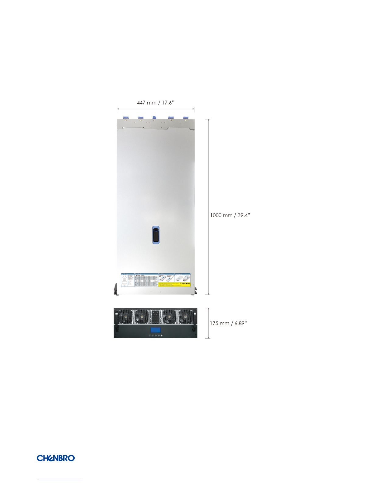
Dimension
(D x W x H)
1000mm x 447mm x 175mm
39.4’’ x 17.6’’ x 6.89’’
Drive Bay 96 x 3.5” Hot-swap HDD
Backplane 4 x 22-port 12Gb/s SAS3/SATA3 Passive Backplane.
4 x 2-port 12Gb/s SAS3/SATA3 Passive Backplane ( Side-docked )
8 x Internal Expander Card ( Dual Domain )
2 x External Expander Card with Console ( Debug )
Power Supply 1+1 CRPS , 80 Plus Platinum, 2000W ( Default )
185mm x 73mm x 40mm ( D x W x H )
Indicator Front : 1 x Power Status, 1 x UID, 1 x HDD Activity, 1 x Global Failure, 1 x LCM
Rear : 1 x Power Status, 1 x UID
Front Control 1 x Power On/Off Button, 1 x UID Button, 1 x LCM Display with Control keys
Rear Control 2 x RS232 Com Port, 1 x IPMI , 8 x Mini-SAS HD
System Security BMC Module Control
Slot Opening N/A
Cooling Fans (Max) Front : 4 x 8038 Hot-Swap Fan, PWM
Middle : 2 x 8038 Hot-Swap Fan, PWM
Rear : 4 x 8038 Hot-Swap Fan, PWM
Expansion Slot N/A
Front Bezel N/A
Slide Rail Full Travel with CMA
Temperature Operating: 10°C to 35°C (50°F to 95°F)
Non-operating: -40°C to 70°C (-40°F to 158°F)
Humidity Non-operating: 50% to 90%
Net Weight 77.0 Kg
Gross Weight 113.1 Kg
Container Loading 20’:48, 40’:100
Page 7
RM43596 JBOD
Product Overview// │ 7
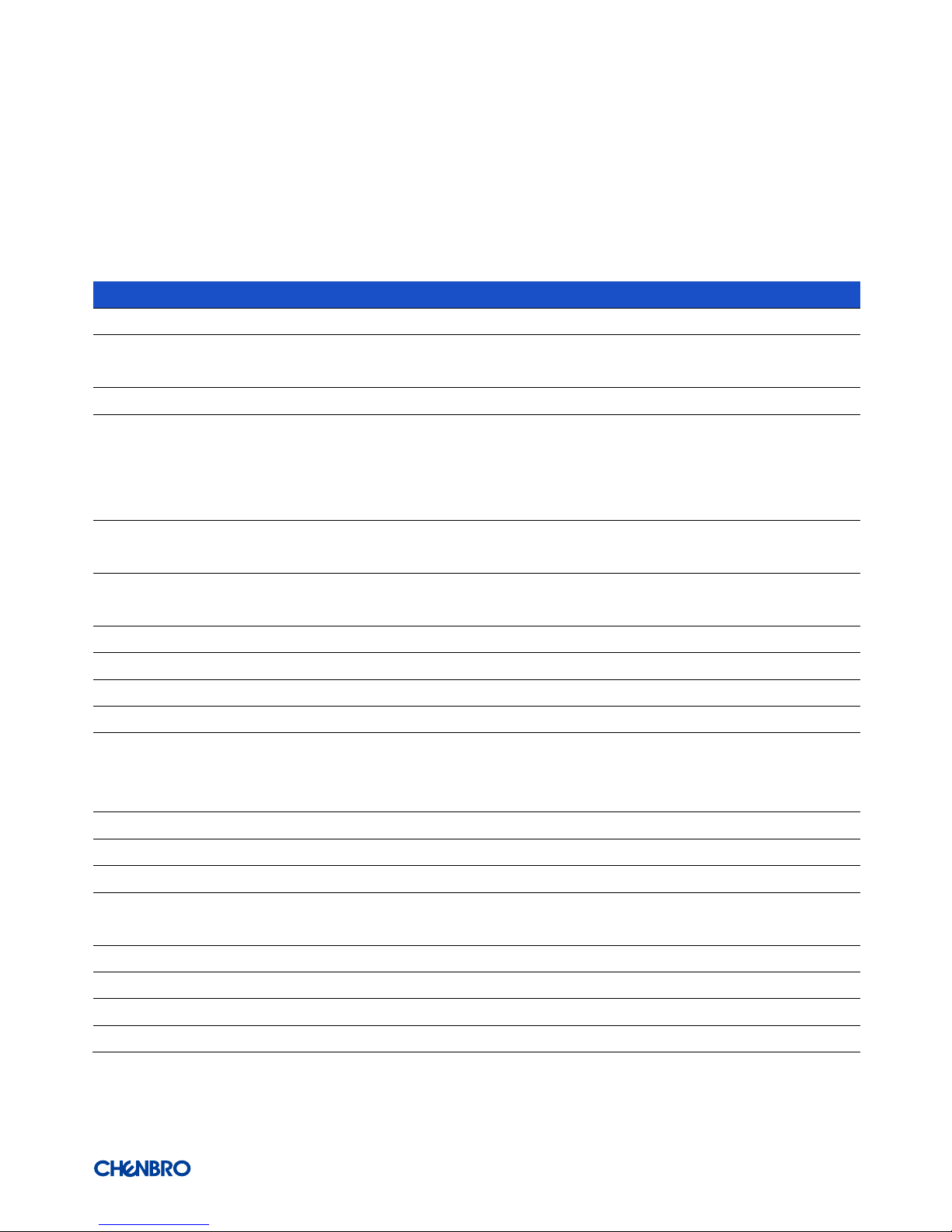
1-1 System Features Overview
Figure 1 Overview
Figure 2 Over view
A. Rack Handle
B. LCM Display
C. Top Cover Latch
D. Front Control Panel
E. 3.5” Storage Drive Bay
F. Front Hot-Swap Fan Module
G. Middle Fixed Fan Module
H. Internal Expander Cards
Page 8
RM43596 JBOD
Product Overview// │ 8
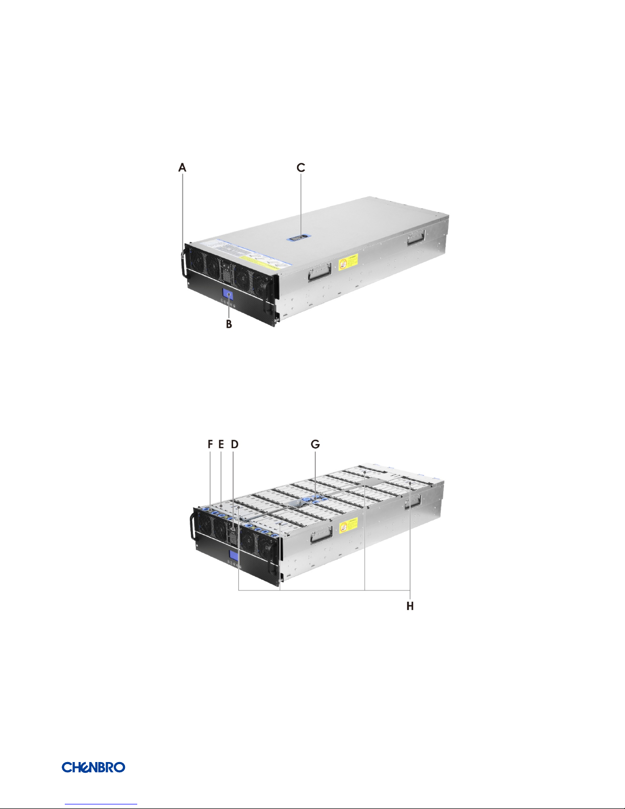
1-2 Front Panel
Figure 3 Front panel
A. Rack Handles
B. Front Control Panel
C. LCM Display
D. Front Hot-Swap Fan Module
Page 9
RM43596 JBOD
Product Overview// │ 9
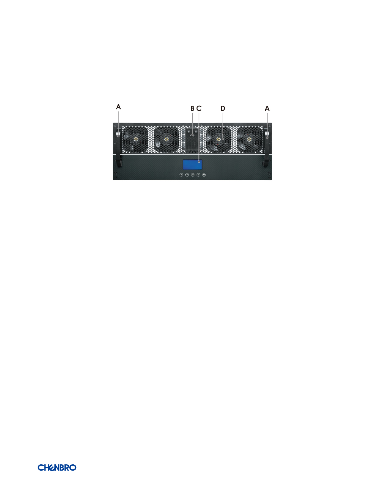
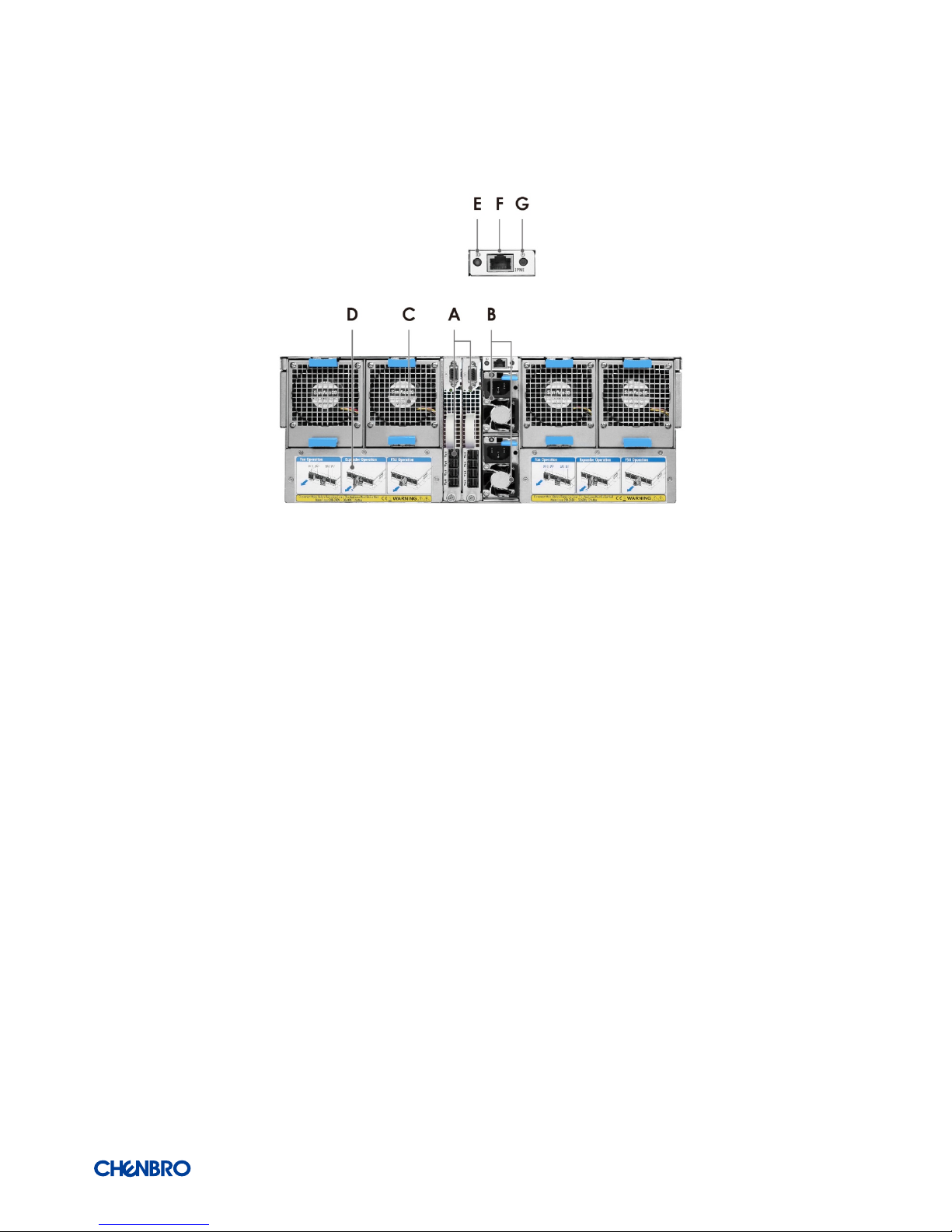
1-3 Back Panel
Figure 4 Back panel overview
A. External Expander Cards
B. CRPS PSU
C. Rear Hot-Swap Fan Module
D. QIG Label
E. UID Button
F. IPMI Port
G. Power Button
Page 10
RM43596 JBOD
Product Overview// │ 10
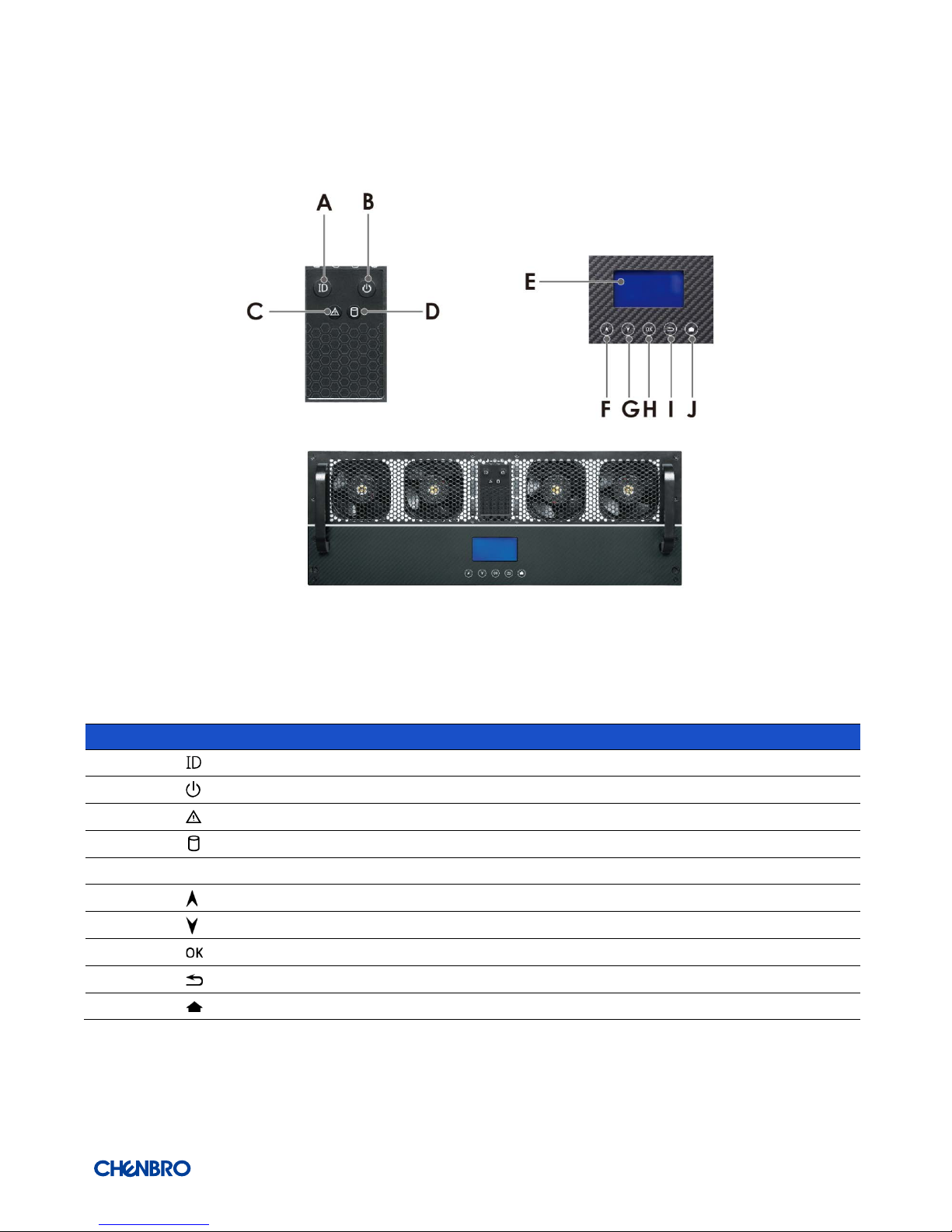
1-4 Front Control Panel
Figure 5 Front control panel
Table 2 Front control panel
Label ICON Indicator, button, or connector
A
UID Button/LED
B
Power LED
C
System Alarm LED
D
HDD Activity LED
E LCM Display
F
Page Up
G
Page down
H
Enter
I Return
J
Home
Page 11
RM43596 JBOD
Product Overview// │ 11
1-5 Chassis Dimensions
Figure 6 Chassis dimensions
Page 12

RM43596 JBOD
Product Overview// │ 12
1-6 Available Rack Mounting Kit Options (Refer to “Installation”)
Advisory Note – Available rack and cabinet mounting kits are not designed to support shipment of the server system while installed
in a rack. If you chose to do so, Chenbro advises you to verify your shipping configuration with appropriate shock and vibration
testing before shipment. Chenbro does not perform shipping tests which cover the complex combination of unique rack offerings
and custom packaging options.
Caution: Exceeding the specified maximum weight limit of a given rail kit or misalignment of the server in the rack may result in
failure of the rack rails, causing damage to the system or personal injury. Two persons to operate or the use of a mechanical assist
tool to install and align the server into the rack is highly recommended.
Available rack mounting kits:
Table 3 Slide rail options
Part Number
384-43503-3300A0
Rail Dimension (mm/inch) 964/37.9"
Applicable Cabinet-post to post (mm/inch) 668~936/26.3"~36.9"
3 Section/2 Section 2 Section
Traveling Distance (mm/inch) 950/37.4"
Support chassis width 438
Loading (kg) 130 kg
Max. Static Loading (kg) for UL 249 kg
Tool-less/Non tool-less Yes
Support CMA Yes
Page 13

RM43596 JBOD
Product Overview// │ 13
1-7 System Level Environmental Specifications
The following table defines the system level specifications under operating and non-operating environments.
Table 4 System environmental specifications summary
Parameter Specification
Temperature Operating 5º C to 35º C (41º F to 95º F)
Temperature Non-Operating -40º C to 70º C (-40º F to 158º F)
Humidity
Non-Operating
50% to 90%, non-condensing with a maximum wet bulb of 28° C (at
temperatures from 25° C to 35° C)
Shock
Unpackaged Trapezoidal, 25 g, velocity change is based on Product weight
Vibration Operating 5 Hz @ 0.0002 g2/Hz to 350 Hz @ 0.0002 g2/Hz
Input acceleration is 0.26 g RMS
10 minutes per axis for all 3 axes on all samples
Random control limit tolerance is ± 3 dB
EMI
Pre-scan
Radiated Emissions International (CISPR 22) Radiated Limits for Radiating Class A & B Devices
Frequency range(MHz)/Class A and Class B(10 meters limits):
30MHz to 300 MHz / 40 dB ( V/m) and 30 dB ( V/m)
200MHz to 1000 MHz / 47 dB ( V/m) and 37 dB ( V/m)
RVI Operating HDD class
Class 1: Highest performance, reliability, and data integrity
Class 2: A second tier of performance, reliability, and data integrity
HDD I/O throughput degradation SPEC
Pass/Fail Criteria
No functional failure during test or post test diagnostics.
Requirement to pass test is based on IOMeter data throughput (in IO’s per
second) expressed as a percent of Test HDD maximum theoretical
baseline performance
Class1: > 90% of baseline for 4K Random Writes and > 80% of baseline for
128K Sequential Writes.
Class2: > 85% of baseline for 4K Random Writes and > 75% of baseline for
128K Sequential Writes.
Mix: > 80% of baseline for 4K Random Writes and > 70% of baseline for
128K Sequential Writes.
Packaged
Vibration
Non-Operating ISTA (weight over 68 kg, 1B ; weight equal or less than 68 kg, 1A)
Packaged Drop
Non-Operating Drop height change is based on product weight
Non-palletized product:
Investigation: Test requirement is 6 face drops, 8 corner drops and 12
edge drops for a total of 26 drops.
Validation: Test requirement is 6 face drops, 2 corner drops and 3 edge
drops for a total of 11 drops.
Palletized product: (Both investigation and validation)
Perform two bottom drops at the specified height, 10 bottom drops at
one half of the specified height.
Perform 4 rotational edge drops (one per edge) at the specified height.
Page 14

RM43596 JBOD
Product Overview// │ 14
1-8 System Packaging
The original Chenbro packaging, where the server system is delivered, is designed to provide protection for L6 configuration and
tested to meet ISTA (International Safe Transit Association) Test Procedure 1A (2008). The packaging is also designed to be reused
for shipment after the system integration has been completed.
The original packaging includes the shipping box, and various protective inner packaging components, which are designed to
function together as a protective packaging system. When reused, all of the original packaging material must be used, including box
and each inner packaging component. In addition, all inner packaging components MUST be reinstalled in the proper location to
ensure adequate protection to the system for subsequent shipment.
Table 5 Syst em packaging information
Part Number Single/ Bulk Form factor (mm) Support level
387-43596-3300A0 Single 1209 x 639 x 120
L6
NOTE: The design of the inner packaging components does not prevent improper placement within the packaging
assembly. There is only one correct packaging assembly that will allow the package to meet the ISTA (International Safe
Transit Association) Test Procedure 1A (2008).
Failure to follow the specified packaging assembly instructions may result in damage to the system during shipment.
Table 6 Product weight information
Product
Unpackaged Net Weight
(kg)
Packaged Gross Weight
(kg)
Unpackaged Net Weight
(lbs)
Packaged Gross Weight
(lbs)
RM43596 77.0 113.1 169.8 249.3
NOTE: An L6 system does not include M/B, processors, memory, drives, or add-in cards. It is the system configuration as
shipped from Chenbro. Weights of integrated system (system configurations that include the items above) will vary
depending on the final system configuration.
Page 15

RM43596 JBOD
/ System Components Removal and Installation │ 15
2. System Components Removal and Installation
RM43596 supports for a variety of different storage option:
96 x 3.5” Hot-Swap SAS/SATA HDD
Support for different storage and peripheral options will vary depending on the system model and/or available accessory options
installed.
BEFORE YOU BEGIN
WARNING: Watch out Safety and ESD precautions instructions before installing the server.
Page 16

RM43596 JBOD
/ System Components Removal and Installation │ 16
2-1 Top Cover Removal and Installation
Figure 7 Top cover installation
1. Align the guide pins of this cover with the grooves on the chassis base, and install the cover vertically as shown.
(5 guide pins for both side)
NOTE: Keep the latch vertical.
2. Press the latch to lock.
3. Secure with 4 screws as shown.
Figure 8 Top cover removal
1. Loosen 4 screws on the cover as shown.
2. Pull the latch as shown to release the cover.
3. Remove it by both hands to hold each side.
Page 17

RM43596 JBOD
/ System Components Removal and Installation │ 17
2-2 External Hot-Swap HDD Assembly Removal and Installation
Figure 9 3.5” hot-swap HDD assembly installation
1. With the open latch, insert the HDD assembly into the drive bay as shown until the bottom of chassis base.
NOTE: Watch out the direction of HDD assembly while inserting.
2. Push the latch when it is secured with a click.
Figure 10 3.5” hot-swap HDD assembly removal
1. Open the latch to release the HDD assembly as shown.
2. Pull the HDD assembly out of drive bay.
Page 18

RM43596 JBOD
/ System Components Removal and Installation │ 18
Figure 11 3.5” HDD installation (tool-less type)
1. Slide in the HDD until align the anchor point of HDD tray.
2. Push down the HDD when it is secured with a click.
Figure 12 3.5” HDD removal (tool-less type)
1. Bottom up the HDD tray as shown.
2. Press your 2 thumbs on the HDD as shown.
NOTE: Watch out the direction of HDD assembly while inserting.
NOTE: Please operate this on a stable surface in case the HDD dropping unexpectedly.
NOTE: To avoid injury, be careful of the sharp corners and rough edges on HDD tray.
3. Lift the other side with your other fingers and release the HDD.
Page 19

RM43596 JBOD
/ System Components Removal and Installation │ 19
2-3 System Maintenance
Figure 13 Installation of whole system into the rack (tool-less type)
1. Push the system all the way into the cabinet by 2 persons or more.
2. Secure the system with thumb screws on both sides as shown.
Figure 14 Removal of whole system from the rack (tool-less type)
1. Loosen the thumb screws on both sides as shown.
2. Pull the system out of cabinet by 2 persons or more.
Page 20

RM43596 JBOD
/ System Components Removal and Installation │ 20
2-4 Fan Module Removal and Installation
Figure 15 Front fan module installation (8038)
Figure 16 Front fan module installation (8038)
1. Hold the finger grips of fan brackets as shown.
NOTE: Ensure that the arrow sticker on the fan is facing the back of the chassis.
2. Insert the fan module into the fan cage until it is locked with a click.
3. Place the shock-absorbing pads on the front fan modules.
Page 21

RM43596 JBOD
/ System Components Removal and Installation │ 21
Figure 17 Front fan module removal (8038)
Figure 18 Front fan module removal (8038)
1. Remove the shock-absorbing pads on the front fan modules.
2. Grasp and press the fan brackets by the finger grips to release the fan module vertically as shown.
3. Pull it outward and disengage from fan cage.
Page 22

RM43596 JBOD
/ System Components Removal and Installation │ 22
Figure 19 Middle fan modules Installation (8038)
1. Hold the finger grips of fan brackets as shown.
NOTE: Ensure that the arrow sticker on the fan is facing the back of the chassis.
2. Insert the fan module until it is secured with a click.
Figure 20 Middle fan modules removal (8038)
1. Grasp and press the fan brackets by the finger grips to release the fan module vertically as shown.
2. Pull it outward and disengage from fan cage.
Page 23

RM43596 JBOD
/ System Components Removal and Installation │ 23
Figure 21 Rear fan modules installation (8038)
1. Hold the latches of rear fan module.
2. Insert the fan module to the rear fan cage until it is secured with a click.
Figure 22 Rear fan modules removal (8038)
1. Press and hold the latches of rear fan module.
2. Disengage the fan module from the rear fan cage.
Page 24

RM43596 JBOD
/ System Components Removal and Installation │ 24
2-5 Internal/External Expander Card Removal and Installation
Figure 23 Internal expander card installation
1. Align the slot of the internal expander card with the guide pin on the chassis as shown, and install the card vertically until it
reaches the Air Max connectors.
2. Press the lever to secure it.
Figure 24 Internal expander card removal
1. Open the internal expander card lever.
2. Pull it out of chassis base.
Page 25

RM43596 JBOD
/ System Components Removal and Installation │ 25
Figure 17 External expander card installation
1. Slide the external expander card into the chassis as shown.
2. Secure it with a thumb screw clockwise.
Figure 17 External expander card removal
1. Loosen the thumb screw anti-clockwise on external expander card.
2. Hold the bar bracket and pull it out of chassis.
Page 26

RM43596 JBOD
/ System Components Removal and Installation │ 26
2-6 PSU Removal and Installation
Figure 25 CRPS PSU installation
1. Grasp the finger grip with your fingers except the thumbs while pressing and holding the PSU latch with 1 thumb.
2. Slide into the chassis until it is secured with a click.
Figure 26 CRPS PSU removal
1. Press and hold the PSU latch with your thumb, and grasp the finger grip with other fingers.
2. Pull PSU out of the cage.
Page 27

RM43596 JBOD
/ System Components Removal and Installation │ 27
2-7 Slide Rail Installation
Figure 27 Slide rail installation-1 (84H314610-003)
1. Attach the inner rail to the chassis base while aligning T pins on the side of the system with the slots on the inner rail.
Figure 28 Slide rail installation-2 (84H314610-003)
2. Engage T pins with the slots on the inner rail as shown.
3. Secure the inner rail with 1 screw as shown.
Page 28

RM43596 JBOD
/ System Components Removal and Installation │ 28
Figure 29 Slide rail installation-3 (84H314610-003)
4. Install the system into the rack by 2 persons or more.
Page 29

RM43596 JBOD
/ Backplane │ 29
3. Backplane
Each drive tray includes separate LED indicators for drive activity and drive status. Light pipes integrated into the drive tray direct
light emitted from LEDs mounted next to each drive connector on the backplane to the drive tray faceplate, making them visible
from the front of the system.
Figure 30 3.5” Drive tray/internal expander drive tray LED identification
Table 7 Drive power LED/activity LED behavior
LED ICON LED Color Behavior Condition
A
Activity LED
Green Stay on Access
Red Solid on Failure
1Hz blink Rebuild
4Hz blink Locate
B
Activity LED Green 1Hz blink Access
C
Activity LED Red Stay on SAS signal error
NOTE: The drive activity LED is driven by signals coming from the drive itself. Drive vendors may choose to operate the activity
LED different from what is described in the table above. Should the activity LED on a given drive type behave differently than
what is described, customers should take the drive vendor specifications as a reference for the specific drive model to
determine what the expected drive activity LED operation should be.
Page 30

RM43596 JBOD
/ Backplane │ 30
3-1 Storage Backplane Options
RM43596 supports below backplanes :
2 x 24-port 3.5” SAS/SATA SAS29-pin passive backplane (Front)
2 x 24-port 3.5” SAS/SATA SAS29-pin passive backplane (Rear)
8 x 12Gb/s SAS Expander Card (Internal)
2 x 12Gb/s SAS Expander Card (External)
1 x 12Gb/s BMC Module
All available SAS/SATA backplanes include the following common features:
12Gb/s SAS and 6Gb/s SAS/SATA
SFF-8680 12Gb/s rated drive interface connectors, providing both power and I/O signals to attached devices
Hot swap support for SAS/SATA devices
I2C interface from a 4-pin connector for device status communication to the BMC over SMBus
LCM Display to indicate drive activity and status for each attached device
Functionality
The microcontroller has a master/slave I2C connection to the server board BMC. The microcontroller is not an IPMB compliant device.
The BMC will generate SEL events by monitoring registers on the HSBP microcontroller for DRIVE PRESENCE, FAULT, and RAID
REBUILD in progress.
Page 31

RM43596 JBOD
/ Backplane │ 31
3-2 3.5” 24-Port 12Gb/s SATA/SAS Passive Backplane (Front-Right/Front-Left)
Table 8 Backplane specifications
Specification
Host Interface Mini SAS HD
HDD Interface SAS/SATA
Hot-Swap
Yes, allows users to replace devices on line
Display
LED indicates storage device status
Error LED - Red (when HDD is error)
LED indicates Mini SAS HD Link status
Access LED – Green (When SAS signal link is busy)
Error LED - Red (when SAS signal link is error)
Environment Monitor Temperature sensor
Connectors 1. 26 x SFF-8482
2. 2 x Mini-SAS HD connectors
3. 10 x High-Speed backplane connectors
4. 1 x 8-pin Mini-Fit Power connector
5. 2 x 6-pin Micro-Fit Power connectors
Dimension 450.7(L) x 169.2(W) x 2.4(H) mm
Material FR4 8 layers
Figure 31 Backplane front view (front-right)
AFR. HDD_0 ~ HDD_3
BFR. HDD_4 ~ HDD_9
CFR. HDD_10 ~ HDD_15
DFR. HDD_16 ~ HDD_21
EFR. HDD_22
FFR. HDD_23
Page 32

RM43596 JBOD
/ Backplane │ 32
Figure 32 Backplane front view (front-left)
AFL. HDD_24 ~ HDD_27
BFL. HDD_28 ~ HDD_33
CFL. HDD_34 ~ HDD_39
DFL. HDD_40 ~ HDD_45
EFL. HDD_46
FFL. HDD_47
Table 9 Connector and pin header function description
Label Connecter Description
Drawing
G Power The backplane includes one 2 x 4 connector
supplying power to the backplane. Power is routed
to the backplane via a power cable harness from the
power supply modules.
H Mini-SAS HD The backplane includes two multi-port mini-SAS HD
cable connectors providing data signals for twenty
six SAS/SATA drives on the backplane.
I Fan The backplane includes two 2 x 3 connectors
supplying power and signals to the front hot-swap
fan.
J
Temperature Sensor
The backplane includes two temperature sensors
providing data signals to the BMC unit.
K High-Speed Backplane The backplane includes ten High-Speed backplane
connectors providing data signals for the internal
expander card.
Page 33

RM43596 JBOD
/ Backplane │ 33
3-3 3.5” 24-Port 12Gb/s SATA/SAS Passive Backplane (Rear-Right/Rear-Left)
Table 10 Backplane specifications
Specification
Host Interface Mini SAS HD
HDD Interface SAS/SATA
Hot-Swap Yes, allows users to replace storage devices on line
Display
LED indicates storage device status
Error LED - Red (when HDD is error)
LED indicates Mini SAS HD Link status
Access LED – Green (When SAS signal link is busy)
Error LED - Red (when SAS signal link is error)
Environment Monitor Temperature sensor
Connectors
1. 26 x SFF-8482
2. 2 x Mini-SAS HD
3. 10 x High-Speed backplane connectors
4. 1 x 8-pin Mini-Fit power connector
5. 2 x 16-pin power connectors
Dimension 505.0(L) x 157.5(W) x 2.4(H) mm
Material FR4 8 layers
Figure 33 Backplane front view (rear-right)
ARR. HDD_48 ~ HDD_53
BRR. HDD_54 ~ HDD_59
CRR. HDD_60 ~ HDD_65
DRR. HDD_66 ~ HDD_69
ERR. HDD_70
FRR. HDD_71
Page 34

RM43596 JBOD
/ Backplane │ 34
Figure 34 Backplane front view (rear-left)
ARL. HDD_72 ~ HDD_77
BRL. HDD_78 ~ HDD_83
CRL. HDD_84 ~ HDD_89
DRL. HDD_90 ~ HDD_93
ERL. HDD_94
ERL. HDD_95
Table 11 Connector and pin header function description
Label Connector Description
Drawing
G Power The backplane includes two Micro-Fit 3.0mm 2 x 16
connectors
supplying power to the backplane.
Power is routed to the backplane via a power cable
harness from the power supply modules.
J Mini-SAS HD The backplane includes 2 multi-port mini-SAS HD
cable connectors providing data signals for twenty
four SAS/SATA drives on the backplane.
K Fan The backplane includes two 2 x 3 connectors
supplying power and signals to the front hot-swap
fan.
H Temperature Sensor The backplane includes two temperature sensors
providing data signals to the BMC unit.
I High-Speed Backplane The backplane includes ten high-speed backplane
connectors providing data signals for the internal
expander card.
Page 35

RM43596 JBOD
/ Maintenance and Service │ 35
4. Maintenance and Service
DOA (Dead on Arrival)
If the products are found Defect On Arrival, please contact Chenbro’s regional sales or CQE and indicate the defective status via
email along with product photos and description. You may need to return the defective item by request.
The customer should ensure that the products are Defect On Arrival for up to three months from Chenbro’s shipping date and the
damage is not caused by shipping or failures resulting from accident, misuse, abuse, neglect, mishandling, misapplication,
modification, improper operation, improper repair or rework. CHENBRO is not responsible for the cost of replacement including the
delivery cost.
CHENBRO also reserves the right to examine the DOA products. If the damage of DOA products is caused by improper action as
described above, the customer will be liable for paying the related charge having occurred or paying the fee of the replacements if
the DOA products are totally scrapped.
TECHNICAL SUPPORT
Please provide following information when you apply our technical support:
Product model name and/or part number
Product serial number and bar code
Buzzer beeping pattern and/or failure LED flashing pattern
Detailed, specific questions
You may also contact Chenbro’s regional technical supports as below- Website: www.chenbro.com
CENBRO MICOM CO., LTD.
Email: fae@chenbro.com
Tel: +886-2-82265500
Fax: +886-2-82265392
CHENBRO MICOM (USA) INC.
Email: usfae@chenbro.com
Tel: +1-909-947-3200
Fax: +1-909-947-4300
CHENBRO GmbH
Email: defae@chenbro.com
Tel: + 49-2154-8142730
Apply a RMA
number
Return the product for
repair
Receive service
charge notice
Receive the repaired
product
 Loading...