

Chemtrol PC6000, PC3000 Instruction Manual
MANUALPC-2012
© SBCS 2012
i
INSTRUCTION MANUAL
CHEMTROL® PC PROGRAMMABLE
WATER TREATMENT CONTROLLERS
WARRANTY
This CHEMTROL® Controller S/N _________________ is warranted by SANTA BARBARA CONTROL SYSTEMS (SBCS) to be free
from defects in manufacturing and workmanship for a period of FIVE (5) YEARS from the date of purchase for the printed circuit boards
and ONE (1) YEAR for all other components. SBCS will repair or replace at its option any defective part during the warranty period.
Labor, shipping or incidental expenses are specifically excluded from this warranty. For warranty coverage, defective parts should be
returned immediately to your CHEMTROL® Dealer or to our factory postpaid with a copy of your purchase receipt and a description of
the malfunction.
TECHNICAL SUPPORT
US/CANADA
OTHER COUNTRIES
AUSTRALIA
EMAIL
support@chemtrol.com.au
800-621-2279
805-683-8833
1-300-585-820
MANUALPC-2012
ORP AUTO
Calibrate mV 750
Setpoint mV 700
Alarm Low mV 650
Alarm High mV 850
Time Limit min 30
Run Time 10 125
Last Shock 05/01/98
SANITIZER OFF
Calibrate ppm 1.5
Setpoint ppm 1.5
Alarm Low ppm 0.3
Alarm High ppm 3.0
Time Limit min 30
Run Time 10 125
Last Shock 00/00/00
CONTROL TYPE
OFF
Manual
Automatic
Timer
CALIBRATION
1 Point (Zero)
2 Point (Slope)
3 Point (Curve)
ALARM OPTIONS
Feed Lockout YES
Buzzer YES
SHOCK & SAVER
Shock Treatment
Chemical Saver
ON/OFF
Proportional
4-20 mA
Cycle ON 0.1
Cycle OFF 1.0
Deadband
Deadband
Progressive Zone
Top Limit
Bottom Limit
pH AUTO
Calibrate 7.5
Setpoint 7.5
Alarm Low 7.0
Alarm High 8.0
Time Limit min 30
Run Time 10 25
Probe Clean AUTO
CLEAN ON OFF
Mo 19:00 19:05
Tu 00:00 00:00
We 19:00 19:05
Th 00:00 00:00
Fr 00:00 00:00
Sa 19:00 19:05
Su 00:00 00:00
TDS AUTO
Calibrate ppm 1650
Setpoint ppm 2000
Alarm Low ppm 50
Alarm High ppm 2500
Time Limit min 30
Run Time 10 25
Select Scale
Cell Constant 1
TDS Factor 0.5
HEATER AUTO
Calibrate F 82
Setpoint F 82
Alarm Low F 70
Alarm High F 85
Time Limit min 30
Run Time 15 60
Energy Saver AUTO
Heating
Cooling
Acid Feed
Base Feed
Both
Oxidizer
Reducer
Both
ENERGY SAVER
Mo 19:00 06:00
Tu 19:00 06:00
We 19:00 06:00
Th 19:00 06:00
Fr 19:00 06:00
Sa 19:00 06:00
Su 19:00 06:00
PUMP AUTO
P influent psi 25
P effluent psi 20
Flow Rate gp m 800
Alarm low gp m 500
Flow Total Mga 2.20
Heater Delaymi n 20
Water Level AUTO
PUMP ON OFF
Mo 05:00 20:00
Tu 05:00 20:00
We 05:00 20:00
Th 05:00 20:00
Fr 05:00 20:00
Sa 05:00 20:00
Su 05:00 20:00
PRESSURE ALARMS
Low psi + 10
High psi + 50
FLOWMETER FACTOR
Pulses/ga: 6.705
FILTER AUTO
Backwash Date 8/10
Start Time 15:30
Filter Time (min)10.0
Advance (min) 1.0
Number of Filters 5
Pump shutdownYES
Pump Override YES
CONFIGURATION
Initial Setup
Operations
Reports
Communications
Time Interval
P Differential
Time or Pressure
Time & Pressure
Flow rate
Volume of water
Volume or Pressure
Volume & Pressure
Number of Filters5
Priority Valve YES
PUMP Override YES
Stop Time between
valves (sec) 10
COMMUNICATIONS
Phone
Unit ID
Alarm calling YES
INITIAL SETUP
Language
Units
Password
Clock Set
Readings
Data Logging
Model Options
MODEL OPTIONS
ORP Yes
SANITIZER Yes
p H Yes
CONDUCTIVITY Yes
HEATER Yes
PUMP Yes
FILTER Yes
PHONE NUMBERS
1: ______________
2: ______________
3: ______________
4: ______________
5: ______________
6: ______________
SATURATION
Alkalinity 150
Hardness 300
pH 7.5
Temperature 80
Langelier Limits
Langelier Index
Condition OK
OPERATIONS
Audio Alarms YES
Bypass Line YES
Saturation OK
Print Reports
Reset
Battery
Probe Monitor YES
Complete Reset
Partial Reset
ORP
SANITIZER
pH
CONDUCTIVITY
HEATER
PUMP
FILTER
LANGUAGE
English
French
Spanish
UNITS
U.S.
Metric
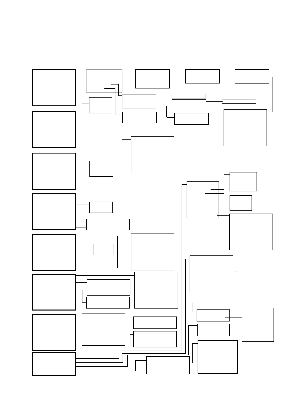
MENU TREE CHEMTROL
(R)
PC CONTROLLERS
Decrease
Increase
SHOCK AUTO
Date 05/08/98
Cycle (days) 7
Time ON pH 18:00
Level pH 7.8
Time ON shock 21:00
Level ORP 820
Time OFF 21:30
View data log
Print Reports
ii
MENU TREE

MANUALPC-2012
1. READ AND FOLLOW ALL INSTRUCTIONS
2. WARNING - To reduce the risk of injury, do not permit children to use this product unless they are closely
supervised at all times.
3. A wire connector is provided on this unit to connect a minimum No. 8 AWG solid copper conductor between
this unit and any metal equipment, metal enclosures or electrical equipment, metal water pipe or conduit within 5
feet of this unit.
4. DANGER - Risk of injury.
a) Replace damaged cord immediately.
b) Do not bury cord.
c) Connect to a grounded, grounding type receptacle only.
5. WARNING - This product must be connected to a power source equipped with a ground-fault circuit interrupter
(GFCI). The GFCI must be tested before each use. With the product operating, open the service door. If the
product stops operating, this merely indicates that the door is equipped with an electrical interlock. Next, push the
test button on the GFCI and close the service door. The product should not operate. Now open the service door,
push the reset button on the GFCI and close the service door. The product should now operate normally. If the
product fails to operate in this manner, there is a ground current flowing indicating the possibility of an electric
shock. Disconnect the power until the fault has been identified and corrected.
8. DANGER - Risk of electric shock. Install at least 5 feet (1.5 m) from inside wall of tub or spa using nonmetallic
plumbing.
7. DANGER - Risk of electric shock. Do not permit any electric appliance, such as a light, telephone, radio, or
television, within 5 feet (1.5 m) of a spa or hot tub.
8. WARNING - To reduce the risk of injury:
a) The water in a spa should never exceed 40 ºC (104 ºF). Water temperatures between 38 ºC (100 ºF) and
40 ºC (104 ºF) are considered safe for a healthy adult. Lower water temperatures are recommended for
young children and when spa use exceeds 10 minutes.
b) Since excessive water temperatures have a high potential for causing fetal damage during early months of
pregnancy, pregnant or possibly pregnant women should limit spa water temperatures to 38 ºC (100 ºF).
c) Before entering a spa or hot tub, the user should measure the water temperature with an accurate
thermometer since the tolerance of water temperature-regulating devices varies.
d) The use of alcohol, drugs or medication before or during spa or hot tub use may lead to unconsciousness
with the possibility of drowning.
e) Persons suffering from obesity or with a medical history of heart disease, low or high blood pressure,
circulatory system problems or diabetes should consult a physician before using a spa.
f) Persons using medication should consult a physician before using a spa or hot tub since some medication
may induce drowsiness while other medications may affect heart rate, blood pressures and circulation.
iii
IMPORTANT SAFETY INSTRUCTIONS
Specified by ITS Testing Services for Swimming Pools and Spas
9. SAVE THESE INSTRUCTIONS

MANUALPC-2012
TABLE OF CONTENTS
MENU TREE ...................................................................II
IMPORTANT SAFETY INSTRUCTIONS .......................II
IMPORTANT SAFETY INSTRUCTIONS ......................III
TABLE OF CONTENTS ............................................... IV
LIST OF FIGURES .........................................................3
CHAPTER I - INTRODUCTION ......................................1
Water Maintenance ...........................................................1
Reference Manuals........................................................1
CONTROLLER FEATURES.................................................2
New Features....................................................................2
Models...............................................................................2
Automated Water Treatment .............................................2
Control Functions ..............................................................2
Free Chlorine.................................................................3
Free Chlorine control .....................................................3
ORP control ...................................................................3
Probe Failure Analysis ......................................................3
CONTROL PANEL ...............................................................4
LCD Display Screen ..........................................................4
Display Readings ..............................................................4
Data Entry Keyboard ......... E
Remote Communications ..................................................4
PROGRAM MENUS .............................................................5
Initial Screens....................................................................5
Display Screens ................................................................5
Main Menus and Submenus..............................................5
Alarm Displays .................. Error! Bookmark not defined.
CHAPTER II - INSTALLATION ......................................6
SAFETY NOTICE .................................................................6
UNPACKING........................................................................6
INSTALLATION REPORT....................................................6
TECHNICAL SUPPORT.......................................................6
PRINCIPLE OF INSTALLATION..........................................6
CONTROLLER CABINET ....................................................6
LOCATION...........................................................................6
ELECTRICAL .......................................................................8
Electrical Codes ................................................................8
AC Power Input .................................................................8
Grounding (GFI) ................................................................8
Main Power Interlock.........................................................8
Panel Interlock ..................................................................8
PC Boards.........................................................................8
Power Board .....................................................................8
115V/230V Power Transformer ........E
defined.
Relay Jumpers (PC7000) ..................................................8
rror! Bookmark not defined.
rror! Bookmark not
iv
Relays and Fuses ............. E
Remote Alarm ................................................................... 9
Mother Board ....................................................................9
Sensor Connections.......................................................... 9
Buzzer............................................................................... 9
Display Brightness ............................................................9
Backup Battery................................................................ 11
Remote Communications................................................ 11
Multiple Serial Connections (Option)............................... 11
4-20 mA Converter Boards .............................................12
Field Installation .............................................................. 12
4-20 mA Connections ..................................................... 12
PPM Sensor Board .........................................................12
PLUMBING ........................................................................13
Installation of Sensors..................................................... 13
In-line Installation (2" Pipe) ............................................. 13
Flow Cell Assembly......................................................... 13
Sensor Cell Cabinet (Option) .......................................... 13
Water Flow...................................................................... 14
Paddle Wheel Rotary Flow Switch .................................. 14
PPM SENSORS ................................................................. 15
PPM Sensor Flow Cell .................................................... 15
PPM Sensor Installation.................................................. 15
ORP AND PH SENSORS....................................................16
Properties........................................................................ 16
Packaging .......................................................................16
Sensor cables .................................................................16
Electrical Interference .....................................................16
Storage and Winterizing.................................................. 17
Sensor Warranties ..........................................................17
TEMPERATURE SENSOR ................................................ 17
CONDUCTIVITY SENSOR.................................................17
FLOW SENSOR.................................................................18
Flow Sensor Location ..................................................... 18
Flow Sensor Saddles ...................................................... 18
Flow Sensor Connections ............................................... 18
PRESSURE TRANSDUCERS ........................................... 19
Transducer Connections ................................................. 19
WATER LEVEL SENSOR .................................................. 19
Installation....................................................................... 19
Maintenance ................................................................... 19
Figure 28 - Optical Level Sensor..................................... 19
CHEMICAL FEEDERS....................................................... 20
WARNING: Tank Sizing .................................................. 20
Chemical Feed Pumps.................................................... 20
Carbonic Acid (CO2) Valve ............................................. 20
Gas Chlorinator............................................................... 20
Erosion Feeders.............................................................. 20
Back Diffusion ................................................................. 20
FILTER BACKWASH......................................................... 21
Main Pump Shutoff ......................................................... 21
Single Filter Backwash.................................................... 21
Multiple Filter Backwash .................................................21
Backwash Stager ............................................................ 21
Electrical Valves.............................................................. 21
Hydraulic Valves .............................................................21
Pneumatic Valves ...........................................................21
rror! Bookmark not defined.
CHAPTER III - STARTUP ............................................ 22

MANUALPC-2012 Page 1
CONTROLLER STARTUP .................................................22
Initial Reset .....................................................................22
Configuration Menu .........................................................22
Alarm Buzzer...................................................................22
Bypass Line.....................................................................22
Battery Check..................................................................22
PPM Board Initialization ..................................................22
CHEMICAL CONTROL ......................................................22
Initial Activation of Sensors .............................................22
Bypass Line Test.............................................................22
Water Chemistry Adjustment...........................................22
Water Sampling...............................................................22
pH Calibration .................................................................22
pH Feed (Acid or Base)...................................................23
pH Setpoint .....................................................................23
ORP Calibration ..............................................................23
ORP Setpoint ..................................................................23
Sanitizer Calibration ........................................................23
Time Limits......................................................................23
Shock Treatment .............................................................23
Chemical Saver...............................................................23
WATER SATURATION ......................................................23
CHAPTER IV - CONTROLLER OPERATION..............24
Access.............................................................................24
Default Setup ..................................................................24
8 - CONFIGURATION MAIN MENU ...................................24
8.1 - INITIAL SETUP SUBMENU ....................................25
8.1.1 - Language..........................................................25
8.1.2 - Units .................................................................25
8.1.3 - Code Number ...................................................25
8.1.4 - Clock ................................................................26
8.1.5 - Readings ..........................................................26
8.1.6 - Data Logging ....................................................26
8.1.7 - Model Options ..................................................26
8.2 - OPERATIONS SUBMENU......................................27
8.2.1 - Audio Alarms ....................................................27
8.2.2 - Bypass Line ......................................................27
8.2.3 - Langelier Saturation Index................................27
8.2.4 - Reset ................................................................28
8.2.5 - Backup Battery .................................................28
8.2.6 - Probe Monitor ...................................................28
8.3 - REPORT SUBMENU ..............................................28
8.3.1 - View Data Log ..................................................28
8.3.2 - Print Reports.....................................................29
On-Site Printing ...........................................................29
On-Site Download........................................................29
8.4 - COMMUNICATIONS SUBMENU............................30
8.4.1 - Phone Numbers................................................30
8.4.2 - Unit Identification ..............................................30
8.4.3 - Alarm Calling ....................................................30
8.4.4 - 4-20 mA Output ................................................30
1 - ORP MENU....................................................................31
Operation.....................................................................31
1.1 - Control Mode...........................................................31
1.2 - Display and Calibration ...........................................31
1.3 - Setpoint...................................................................31
1.4 - Low Alarm ...............................................................31
1.5 – High Alarm .............................................................32
1.6 - Time Limit ...............................................................32
1.7 - Run Time ................................................................32
1.8 - Last Shock ..............................................................32
1.8.1 - Shock Treatment ..............................................32
1.8.2 - Deshock............................................................32
1.8.3 - Chemical Saver ................................................32
2 - SANITIZER MENU ........................................................ 33
Input Selection ................................................................33
Free Chlorine Control...................................................... 33
Calculated PPM Readings .............................................. 33
2.1 - Display and Calibration ........................................... 33
Free Chlorine Calibration............................................. 33
Calculated PPM Calibration......................................... 33
2.3 - Setpoint...................................................................34
2.4 - Low Alarm............................................................... 34
2.5 - High Alarm .............................................................. 34
2.6 - Time Limit ...............................................................34
2.7 - Run Time ................................................................34
2.8 - Last Shock .............................................................. 34
2.8.1 - Superchlorination .............................................34
2.8.2 - Deshock ...........................................................34
2.8.3 - Chemical Saver ................................................ 34
3 - PH MENU.......................................................................35
Operation ........................................................................35
3.1- Control Mode ...........................................................35
3.2 - Display and Calibration ........................................... 35
3.3 - Setpoint...................................................................35
3.4 - Low Alarm............................................................... 36
3.5 - High Alarm .............................................................. 36
3.6 - Time Limit ...............................................................36
3.7 - Run Time ................................................................36
3.8 - Probe Clean............................................................ 36
4 - CONDUCTIVITY MENU ................................................ 37
Conductivity and TDS .....................................................37
Conductivity or TDS Displays.......................................... 37
4.1- Control Mode ...........................................................37
4.2 - Display and Calibration ........................................... 37
4.3 - Setpoint...................................................................37
4.4 - Low Alarm............................................................... 37
4.5 - High Alarm .............................................................. 37
4.6 - Time Limit ...............................................................38
4.7 - Run Time ................................................................38
4.8 - Select Scale............................................................ 38
4.8.1 - Scale Selection................................................. 38
4.8.2 - Cell Constant....................................................38
4.8.3 - TDS Factor....................................................... 38
5 - TEMPERATURE MENU ................................................ 39
Operation ........................................................................39
5.1 - Control Mode ..........................................................39
5.2 - Display and Calibration ........................................... 39
5.3 - Setpoint...................................................................39
5.4 - Low Alarm............................................................... 39
5.5 - High Alarm .............................................................. 39
5.6 - Time Limit ...............................................................39
5.7 - Run Time ................................................................39
5.8 - Energy Saver .......................................................... 39
6- PUMP MENU.................................................................. 40
Operation ........................................................................40
6.1- Control Mode ...........................................................40
6.2 - Influent Pressure..................................................... 41
Pressure Alarms.......................................................... 41
Calibration ...................................................................41
6.3 - Effluent Pressure ....................................................41
Differential Pressure ....................................................... 41
6.4 - Flow Rate.................. E
6.5 - Flow Total ................. Error! Bookmark not defined.
6.6 - Heater Delay (Cooldown Safety) ...........................43
6.7 - Water Level Control ................................................ 43
7 - FILTER MAIN MENU..................................................... 44
Filter Backwash............................................................... 44
7.1 - Automatic Backwash............................................... 44
7.1.2 - Pressure Differential.........................................45
rror! Bookmark not defined.

MANUALPC-2012 Page 2
7.1.3 - Time or Pressure Differential ............................45
7.1.4 - Time and Pressure Differential .........................45
7.1.5 – Flow Rate.........................................................45
7.1.6 – Volume of Water ..............................................46
7.1.7 – Volume or Pressure Differential .......................46
7.1.8 - Volume and Pressure Differential .....................46
Safety Shutoff ..............................................................46
7.6 - Priority Valve ...........................................................46
7.7 - Pump Shutdown......................................................46
7.8 - Pump Override ........................................................46
CONTROL SUBMENUS.....................................................47
Features ..........................................................................47
X.1 - Control Type ...........................................................47
X.0.1 - Deadband.........................................................47
X.0.2 - Progressive Zone .............................................47
X.1.3 - Automatic Control.............................................48
X.1.4 - Timer Control ...................................................48
CALIBRATION SUBMENUS..............................................49
X.2 - Calibration Options .................................................49
X.2.1 - One-Point Calibration.......................................49
X.2.2 - Two-Point Calibration.......................................49
X.2.3 - Three-Point Calibration ....................................49
SHOCK AND SAVINGS SUBMENUS ................................50
X.8 - Treatment Selection................................................50
X.8.1 - Shock Treatment Program ...............................50
X.8.2 - Deshock Program ............................................50
X.8.3 - Chemical Saver Program .................................50
Limit Timers (Overfeed Safety) ....................................... 57
Timer Settings .............................................................57
PERIODIC MAINTENANCE............................................... 57
Water Testing.................................................................. 57
Shock Treatment............................................................. 57
Precautions ................................................................. 57
PORTABLE TESTER......................................................... 58
ORP SENSOR TESTING................................................ 58
pH SENSOR TESTING................................................... 58
ORP AND pH SIMULATION ........................................... 58
CONDUCTIVITY AND TEMPERATURE.........................58
TROUBLESHOOTING ................................................. 59
PARTS, ACCESSORIES AND UPGRADES ............... 60
INDEX ........................................................................... 62
CHAPTER V - COMMUNICATIONS ............................51
CHEMCOM
MODEM CONNECTIONS ..........................................................52
COMPUTER SOFTWARE INSTALLATION.....................................52
REMOTE OPERATION .............................................................52
Secondary Units..............................................................52
Duplex Operation ............................................................52
DATA COLLECTION ................................................................53
AUTOMATIC SCANNING ..........................................................53
Direct Scanning...............................................................53
Data Log Download.........................................................54
DATA DISPLAY ......................................................................54
Text Data Display ............................................................54
Graphic Data Display ......................................................54
PROGRAM .....................................................51
™
CHAPTER VI - MAINTENANCE...................................55
CONTROLLER MAINTENANCE........................................55
Regular Maintenance ......................................................55
The Acid Test ..................................................................55
Sensor Cleaning..............................................................55
PPM Sensor: ...............................................................55
ORP and pH Sensors: .................................................55
Conductivity Sensor.....................................................55
PPM Sensor Storage.......................................................55
ORP and pH Sensor Storage ..........................................55
Sensor Winterizing ..........................................................55
Battery Replacement.......................................................55
Software Upgrade ...........................................................55
CHEMICAL MAINTENANCE..............................................56
Overview .........................................................................56
pH Control .......................................................................56
ORP and Sanitizer Control ..............................................56

MANUALPC-2012 Page 3
LIST OF FIGURES
Figure 1 - Models Comparision Chart.......................................2
Figure 2 - Equilibrium of Free Chlorine.....................................3
Figure 3 - Control Panel and Main Screen ...............................4
Figure 4 - Remote Computer....................................................4
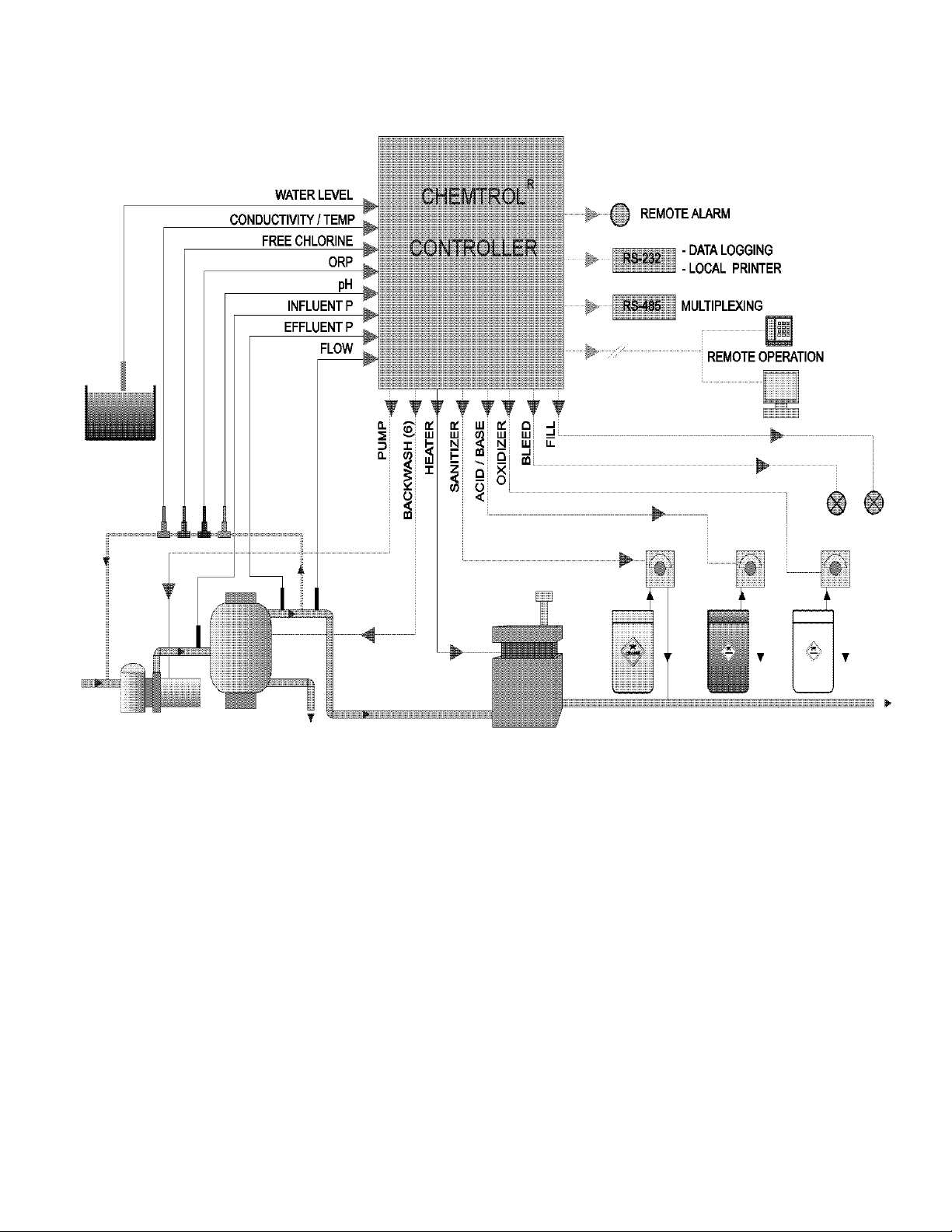
Figure 5 – Installation Schematics............................................7
Figure 6 - Mother Board ........... Error! Bookmark not defined.
Figure 9 - Power Board ............ Error! Bookmark not defined.
Figure 10 - Multiplex Connections ..........................................11
Figure 11 - Installation of Optional Boards .............................12
Figure 12 - 4-20 mA Converter Board ....................................12
Figure 13 - Sensor Installation................................................13
Figure 14 - Flow cell Assembly .
Figure 15 - Sensor Cell Cabinet (Option)............................13
Figure 16 - PPM Sensor Flow Cell .........................................15
Figure 17 - PPM Sensor Package ..........................................15
Figure 18 - ORP and pH Sensors...........................................16
Figure 19 - Temperature Sensor ...........................................17
Figure 20 - Conductivity Sensor .............................................17
Figure 21 - Flow Sensor Installation .......................................18
Figure 22 - Model 2536 Flow Sensor .....................................18
Figure 23 - Model 2540 Flow Sensor .....................................18
Figure 24 - Saddle for FS2536 ...............................................18
Figure 25 - Saddle for FS 2540 ..............................................18
Figure 26 - Pressure Transducer............................................19
..........................................13
Figure 27 - Optical Level Sensor............................................ 19
Figure 28 - Optical Beam Path ............................................... 19
Figure 29 - Water Level Assembly ......................................... 19
Figure 30 - Erosion Feeder Control........................................ 20
Figure 31 - Single Filter Backwash......................................... 21
Figure 32 - Multiple Filter Backwash ...................................... 21
Figure 33 - On-screen Data Log............................................. 28
Figure 34 - Proportional Feed Rate........................................ 48
Figure 35 - CHEMCOM™ Program Menu.............................. 51
Figure 36 - CHEMCOM™ System Setup ............................... 51
Figure 37 - CHEMCOM™ Facility Menu ................................ 51
Figure 38 - CHEMCOM™ Facility Selection ..........................52
Figure 39 - CHEMCOM™ Secondary Units ........................... 52
Figure 40 - CHEMCOM™ Remote Operation Screen............ 52
Figure 41 - CHEMCOM™ Automatic Scanning .....................53
Figure 42 - CHEMCOM™ Scan Facilities ............................. 53
Figure 43 - CHEMCOM™ Manual Scanning.......................... 53
Figure 44 - CHEMCOM™ Recent Scans ............................... 53
Figure 45 - CHEMCOM™ Data Display ................................. 54
Figure 46 - CHEMCOM™ Text Data Display ......................... 54
Figure 47 - CHEMCOM™ Graphic Data Display....................54
Figure 48 - PORTA-PROBETM Portable Tester......................58
Figure 49 - pH / mV Scale...................................................... 58

MANUALPC-2012 Page 1
PLATE COUNT
CHAPTER I - INTRODUCTION
Congratulations on your selection of a CHEMTROL® PC
Programmable Controller for your water treatment.
CHEMTROL® Automation uses advanced electronic sensing
technology to monitor and control the most control critical
parameters in water, such as sanitizer activity, pH,
temperature, conductivity or total dissolved solids (TDS).
These are all essential for maintaining safe and enjoyable
water.
Water Maintenance
The primary purpose of water maintenance is to maintain clean
water that meets the bacteriological and physiological
requirements of state and local Health Departments, as shown,
for example, in the table for the State of California.
Equally important is the protection of the equipment from the
aggressiveness of water and its constituents.
The guidelines adopted by the National Spa and Pool Institute
(NSPI), as shown in the second table.
For chemical automation, we recommend:
- Adequate filtration with a maximum turnover rate of six
hours for a pool or 30 minutes for a spa,
- Proper water balance with a pH between 7.4 and 7.6,
alkalinity between 80 and 120 ppm (mg/l) and Langelier
Saturation Index between 0 and 0.3,
- Minimum Free Chlorine level of 1.0 ppm (mg/l) ,
- Oxidation-Reduction Potential (ORP) above 650 mV,
- Total Dissolved Solids (TDS) less than 1,500 ppm (mg/l).
- If required, stabilization not exceeding a cyanuric acid
level above 40 ppm (mg/l),
CHEMTROL® PC controllers are designed to automate and
facilitate the attainment of these goals.
Reference Manuals
For more information on water treatment, see the Maintenance
section in this Instruction Manual or refer to one of the
following reference manuals:
- “Basic Pool and Spa Technology”
National Spa and Pool Institute (NSPI)
- “Pool/Spa Operators Handbook”
National Swimming Pool Foundation(NSPF)
- “Aquatic Facility Operator Manual
National Recreation and Park Association (NRPA).
1986 CALIFORNIA HEALTH CODE
for Swimming Pools
CLARITY
STANDARD
at 35o, per ml
TOTAL COLIFORM COUNT
per 100 ml
Main drain to be
visible from deck.
Less than 200
Bacteria
Less than 2.2
organisms
No eye or skin
PHYSIOLOGICAL QUALITY
irritation.
No objectionable
physiological effect.
TEST
MIN IDEAL MAX
pH 7.2 7.5 7.6
FREE CL, ppm
Non-stabilized
Stabilized
Spa
1
1.5
2
1.5
2
3
COMBINED CL, ppm 0 0 0.2
BROMINE, ppm 2 3 4
OZONE, ppm 0.01 - 1
ORP, mV 650 750 -
CYANURIC ACID, ppm
Outdoor Pool Indoor Pool
Spa
30 0
0
40 0
0
TOTAL ALKALINITY, ppm 100 125 150
TDS, ppm 300 1000 3000
Based on Standards for Public Pools and Spas.
Published in 1988 by the
NATIONAL SPA AND POOL INSTITUTE
2
3
5
100 0
100

MANUALPC-2012 CHAPTER I – INTRODUCTION Page 2
CONTROLLER FEATURES
CHEMTROL® PC Controllers are microprocessor-based
programmable controllers designed for automatic control of
water chemistry, water balance and filtration in swimming
pools, spas, cooling towers and industrial applications.
New Features
This manual introduces two new features:
- On-screen data display, available on all models,
- New solid state PPM sensor for Free Chlorine, available
with PC5000 and PC7000 controllers.
Models
Five different, yet very similar, CHEMTROL® controller models
are covered in this manual: PC2100, PC3000/PC5000, and
PC6000/PC7000. The latter 4 models use similar hardware
and thus are referred to as PC3000 Product Line.
Please refer to Figure 1 showing the standard features and
available options for each model. Note that these models have
few differences and can do mostly all the same functions
based on how they’re equipped. While PC2100 lacks level and
filtration control capability for example, PC5000/PC7000 only
have Free Chlorine control included when compared to their
otherwise identical counterparts PC3000/PC6000, respectively.
Automated Water Treatment
CHEMTROL® PC controllers are advanced automation
systems for water maintenance. Designed around a
sophisticated microprocessor, the controllers display userfriendly menus and submenus on an easy-to-read LCD (Liquid
Crystal Display) screen. All the displays and adjustments are
accessible from menu screens that are laid out in a logical and
intuitive order. They can in fact be used without reference to
the instruction manual.
All sensing devices are connected to the central control
module. That makes it possible to monitor the status of all
operational parameters at a glance. Also, in case of
malfunction or alarm, the operator is immediately alerted.
A 24-hour clock/calendar shows the date and time on the main
screen.
Control Functions
The following display and control functions are:
- Oxidation-Reduction Potential (ORP or Redox) in
millivolts with programmable oxidizer feed, superoxidation
and chemical savings program,
- Sanitizer Concentration in parts per million (ppm) or
milligrams per liter (mg/l) with programmable sanitizer feed,
superchlorination and chemical savings program,
- pH from 0 to 14 with capability for acid and base feed,
- Conductivity in microsiemens/cm or Total Dissolved
Solids (TDS) in ppm or mg/l with capability for programmed
dumping and replacement of water and for addition of three
different chemical additives, such as inhibitor, different
biocides or probe cleaner.
- Heater Control with temperature display in Fahrenheit or
Celsius, programmable heater control, and energy savings
program.
- Water Recirculation with automatic programming or manual
control of main pump, plus display of flowrate in gallons per
minute (gpm) or liters per minute (l/m) and cumulative flow in
Millions of Gallons (Mga) or cubic meters (m3),
- Water Balance and Saturation Condition derived from the
Langelier Saturation Index and showing water balance
conditions as either OK, corrosive or scaling.
- Filtration with display of inlet and outlet pressures and
programmable filter backwashing (PC6000/PC7000 only)
based on choice of time, inlet pressure, pressure differential
or combinations of the above.
OPTIONS PC2100 PC3000 PC5000 PC6000 PC7000
Free Chlorine Control / PPM sensor ● ● √ ● √
ORP Control/ Sensor √ √ √ √ √
pH Control/ Sensor √ √ √ √ √
PPM Display √ √ √ √ √
TDS/ Conductivity Control ● ● ● √ √
Water Level Control – ● ● √ √
Heater Control ● √ √ √ √
Shock Program √ √ √ √ √
Chemical Saver Program √ √ √ √ √
Langlier Saturation Index Display √ √ √ √ √
Safteytimers √ √ √ √ √
Energy Saver Program √ √ √ √ √
Adjustable Setpoints √ √ √ √ √
Proportional Feed √ √ √ √ √
Automatic Data Logging √ √ √ √ √
Influent/ Effluent Pressures ● ● ● √ √
Main Pump Control and Flow Rate ● ● ● √ √
Automated Filter Backwash – ● ● √ √
Remote Computer Operation ● ● ● √ √
Telephone Voice Communications ● ● ● √ √
Recirculation Pump Control ● – ● √ √
Remote Alarm √ √ √ √ √
Autodialer for Alarm Callout ● ● ● ● ●
Sensor Cell Cabinet ● ● ● √ √
Flow Cell Assembly ● √ √ √ √
Safety Flowswitch √ √ √ √ √
4-20mA Data Output ● ● ● ● ●
4-20mA Control ● ● ● ● ●
Ethernet/ Internet w/ Chemcon Software ● ● ● ● ●
RS-485 Direct Computer Operation ● ● ● ● ●
RS-232 for direct download ● √ √ √ √
USB Data Port √ – – – –
SD Card Reader for Firmware Updates √ – – – –
Modbus ● ● ● ● ●
Priority Valve Control - ● ● √ √
Interlock √ √ √ √ √
Waste Pit and Surge Pit Alarms – – – – –
Multiple Backwash Programs – – ● √ √
Full Screen Menus √ √ √ √ √
Compatible w/ all common Sanitizers and A.C.T. Program √ √ √ √ √
5 Year Electronics Warranty √ √ √ √ √
√ Standard Feature ● Optional Add-On – Not Available
Figure 1 - Models Comparision Chart

MANUALPC-2012 CHAPTER I – INTRODUCTION Page 3
Sanitizer Control
CHEMTROL® PC controllers offer two choices for sanitizer
control:
- Direct chlorine control using a membrane solid state
sensor for Free Chlorine (standard on PC5000/PC7000
and available on PC2100/PC3000/PC6000)
- Oxidation-Reduction Potential control for chlorine or
bromine using an ORP sensor with a platinum ring
(available on all PC controllers).
Free Chlorine
When chlorine in any form is introduced in water it forms
Hypochlorous Acid HOCl, which is called Free Chlorine and is
an excellent bactericide.
As shown in Figure 2, HOCl is a weak acid. It dissociates to
produce an hypochlorite ion OCl- and a hydrogen ion H+:
HOCl ========= OCl- + H+
Free chlorine in water is therefore always present in two forms:
- Hypochlorous acid HOCl, which is Fast Acting Free
Chlorine, and
- Hypochlorous ion OCl-, which is a much slower acting
sanitizer.
Note in that same figure that the concentration of HOCl
decreases very rapidly with increasing pH in the range of 7 to
8. At a pH of 7.5, it is equally divided between HOCl and OCL-
.
Free Chlorine control
CHEMTROL® PC5000/PC7000 include true Free Chlorine
control using a solid state sensor with a selective membrane
for Free Chlorine.
The controller displays the concentration of Total Free Chlorine
(HOCl + OCl-) in PPM (parts per million or milligrams/liter). It
does not respond to Bromine and it is not affected by oxidizers.
The Free Chlorine display does not vary with pH.
The PPM setpoint default value on the controller is 1.0 ppm,
which is recommended to kill germs and bacteria and maintain
good water quality. It can be adjusted to meet local conditions
and Health Department requirements.
ORP control
The oxidizing activity of the sanitizer (chlorine or bromine) can
be monitored with a special electrode for Oxidation-Reduction
Potential, called ORP or Redox.
ORP does not measure sanitizer concentration but only the
activity of the more active forms: HOCl or HOBr. As shown in
Figure 2, their concentration varies with pH. Therefore, for
ORP control, it is important to maintain a constant pH in the
water.
Figure 2 - Equilibrium of Free Chlorine
ORP readings are measured in millivolts (mV). They are
valuable because they provide an excellent index of
bacteriological water quality.
In 1971, the third edition of the "International Standards for
Drinking Water Quality" of the WORLD HEALTH
ORGANIZATION (WHO) stated:
"A redox potential of 650 mV (measured between platinum
and calomel electrodes) will cause almost instantaneous
inactivation of even high concentrations of virus. Such a
potential can be obtained with even a low concentration of
free chlorine but only with an extremely high concentration
of combined chlorine."
In 1985, a study of thirty commercial spas by the OREGON
DEPARTMENT OF HEALTH also confirmed 650 mV to be the
minimum value required to prevent growth of germs and
bacteria. Public pools and spas in many European countries
are required by law to maintain an ORP level of 750 mV or
more.
In the US, the 1988 revision of the Standards for Public Spas
published by the NATIONAL SPA AND POOL INSTITUTE
(NSPI) states:
"When chlorine or bromine is used as a primary
disinfectant, ORP can be used as a supplemental
measurement of proper sanitizer activity. The
recommended minimum is 650 mV with no ideal and no
maximum. The use of ORP testing does not eliminate the
need for testing the sanitizer level with standard test kits".
Probe Failure Analysis
All CHEMTROL® PC controllers include the exclusive safety
feature called Probe Failure Analysis.
With this proprietary technology (US Patent No. 5,895,565),
the controller continuously monitors and tests the dynamic
response of the ORP and pH sensors (see page 28). This
important feature allows early detection of probe failure,
thereby avoiding the dangerous out-of-range conditions that
can develop with other controllers that alert the operator only
after a failure has actually occured. This could result in serious
damage and liability.

MANUALPC-2012 CHAPTER I – INTRODUCTION Page 4
CONTROL PANEL
LCD Display Screen
The operator interacts with the controller using the LCD display
screen and the 16-key data entry keypad on the front panel of
the controller, both shown in Error! Reference source not
found.. Newer controllers come equipped with touch screens.
The display shows different screens each consisting of up to
eight lines of text. Each data line can be highlighted using the
UP and DOWN arrow keys to navigate to its submenu using
the LEFT and RIGHT arrow keys.
A line flashes to alert the operator if an alarm condition for that
specific data is met.
For models that do not come equipped with all functions
available, only the applicable screens and menus are shown.
The LCD display screen features backlight illumination for
better viewing at night and in dark areas. To protect the
display, the backlight turns off automatically after a short time
and on again as soon as a key is pressed.
The brightness of the LCD display screen is adjusted at the
factory before shipping. If required, it can be re-adjusted at
any time with a potentiometer on the Mother Board (R16 for
PC2100 or R39 for PC3000 product line).
Display Readings
As shown on the Display Screen (Error! Reference source
not found.), the operator can check all operating parameters
at a glance.
Line 1 shows an ORP reading of 750 mV with the feed pump
in Automatic feed mode (A) and running (>)
Line 2 shows a Sanitizer level of 1.5 ppm with the feed mode
OFF (X)
Line 3 shows a pH reading of 7.5 with the Acid feed mode in
Automatic (A) and the pump not running (no >)
Line 4 shows the Total Dissolved Solids (TDS) at 801 ppm
and bleed valve control OFF (X)
Line 5 shows a Temperature reading of 82 F with the heater
control on Automatic (A)
Line 6 shows Flow Rates of 1.5 and 800 gpm in the Bypass
line and Main line and the Pump in Manual mode (M)
Line 7 shows an Influent Pressure of 25 psi, an Effluent
Pressure of 20 psi and the backwash program in
Automatic mode (A)
Line 8 shows the Date and Time and an indication that the
water saturation condition is OK. The line is
highlighted to give access to the Configuration Menu
Figure 3 - Control Panel and Main Screen
emote Communications
R
CHEMTROL® controller features remote operation by
computer (Figure 4).
Unlike less advanced controllers, the CHEMTROL® PC
operates in true duplex mode with full access to all menus and
submenus.
This means that any change on the controller screen is
immediately reproduced on the remote computer screen.
Similarly, any operation that is performed on the remote
computer screen is reproduced immediately on the controller.
Both the controller as well as your computer have the same
available commands and interface. This facilitates operator
training and allows instant verification and adjustment of all
control parameters anywhere from any remote computer. To
prevent unauthorized access, the controller could be
programmed with different authorization level password
protection.
Please see Chapter V – Communications on the CHEMTROL®
communication software CHEMCOM
Figure 4 - Remote
Computer
TM and how it works.

MANUALPC-2012 CHAPTER I – INTRODUCTION Page 5
WELCOME TO
>ORP
650
mV A
>ORP
710
mV A
PROGRAM MENUS
Initial Screens
When power is applied to the controller, CHEMTROL® PC
displays the Welcome Screen shown on the right. It includes
the firmware version of the operating software installed on the
controller and the factory’s Technical Support phone numbers.
Canada has the same toll-free support numbers as the USA.
These screens can also be accessed at any time from the
Main Display Screen by pressing the LEFT ARROW key.
Display Screens
The Welcome Screen is followed by the main menu showing
the main functions of the controller and their conditions.
The adjustable operational information are shown from left to
right as follows:
1. Operational status arrow indicating outlet activation,
2. Function identification: ORP, SANITIZER, pH,
CONDUCTIVITY, TEMPERATURE, PUMP and FILTER,
3. Function/Sensor readings,
4. Units of measurement (US or metric),
5. Function operational mode:
A: Automatic control,
M: Manual operation,
T: Timer control,
X: OFF.
Main Menus and Submenus
As shown on the Menu Tree included in the manual, there are
several submenus that are accessed directly from the Main
Screen; one for each operating function, and one for system
configuration.
Navigation through the menus is done with the four arrow keys
located on the front panel keypad. To access any menu or
submenu, use the UP and DOWN ARROW keys to highlight
the desired function and press the RIGHT ARROW key. To
exit from any submenu or screen, press the LEFT ARROW
key.
Alarm Displays
Probe failure, out-of-range and overfeed conditions are
indicated on the main screen and submenues with flashing
lines. For probe failure, the display flashes “Probe” on the
corresponding line.
If the display shows an out-of-range or overfeed alarm
condition, press the DOWN ARROW key to the flashing line
and enter that function’s submenu with the RIGHT ARROW
key to determine the cause of alarm.
CHEMTROL® 6000
Version 2.16
TECHNICAL SUPPORT
USA 800-621-2279
PHONE 805-683-8833
FAX 805-683-1893
Welcome Screen
SANITIZER 1.0 ppm X
>ACID 7.5 pH A
COND 2000 uS X
TEMP 82 F A
>PUMP 200 gpm A
FILTER 25 / 20 psi X
08/10/11 5:30 LSI OK
PC5000/7000 Main Display
SANITIZER 1.4 ppm X
>pH 6.7 pH A
COND 1730 uS X
TEMP 79 F A
FLOW 2 4 gpm X
06/03/12 12:47 OK
PC2100 Main Display

MANUALPC-2010 CHAPTER II – INSTALLATION Page 6
CHAPTER II - INSTALLATION
SAFETY NOTICE
See important safety information on the first page of the
manual.
UNPACKING
Immediately upon receipt of your shipment, check the shipping
carton carefully for damage and report any damage directly to
the shipping company. Please report any shortage
immediately to the factory.
Before opening the carton, check the outside label and verify
the model number, voltage, tee size and feed mode. Unpack
the carton carefully and accounting for any of small parts such
as PVC fittings.
The controller carton should include the following:
- Controller Cabinet,
- Sensors as required for selected model,
- Instruction Manual and Warranty Card,
- Installation Report to be mailed back to factory upon
completion of installation,
- Bypass Line Assembly (Optional).
INSTALLATION REPORT
he Installation Report is a triplicate form designed to assure
T
warranty coverage, technical updates and factory support.
1. White copy: to mail back to factory.
2. Pink copy: to Facilities Manager.
3. Yellow copy: to Qualified Dealer.
Upon completion of installation, it must be filled out and signed
by the Qualified Dealer and by the facilities manager.
TECHNICAL SUPPORT
lease take your time to read this detailed Instruction Manual
P
to insure proper installation and operation. If you need further
technical assistance, you can contact your Qualified
CHEMTROL® Representative, call our Technical Department
toll free at 800-621-2279 or e-mail us at
chemtrol@sbcontrol.com.
PRINCIPLE OF INSTALLATION
C
HEMTROL® PC constitutes an integrated command center
for complete monitoring and control of all water treatment
operations, including chemistry, filtration, heating recirculation
pump and water level.
All information provided by the sensors is processed by the
microprocessor on the Mother Board and displayed on the
Main display screen. Command signals are then sent to the
different control outputs on the Power Board (see
ELECTRICAL below).
The schematic of installation in Figure 5 shows the principle of
installation with all options installed. Figure 11 show the details
of installation for the bypass line and sensor cell assembly.
CONTROLLER CABINET
HEMTROL® PC controllers are contained in a rain proof and
C
splash proof NEMA Type 3 cabinets.
For ease of installation, there are two external mounting ears
on the top of the cabinet.
All the electronic and electrical components are mounted
inside the cabinet on two separate PC Boards, the Mother
Board and the Power Board. Outlets are provided on the
bottom of the cabinet for ½" conduits connectors.
LOCATION
ount the cabinet on a wall in a secure location:
M
- More than 10' (3 m) away from the water edge to comply
with electrical code requirements,
- Within 10' (3 m) of the main recirculation line or of the
bypass line - unless special extension cables are used for
the sensors (see Sensor Cables),
- Not exposed to direct sunlight as the LCD display screen will
darken at high temperature,
- Easily accessible to maintenance personnel,
- If possible, in a separate or well-ventilated room as far away
as possible from corrosive chemicals and storage tanks,
- At a safe distance from power transformers, pump motors or
high voltage power lines,
- Safe from unauthorized access or vandalism
MANUALPC-2010 CHAPTER II – INSTALLATION Page 7
Figure 5 – Installation Schematics

MANUALPC-2010 CHAPTER II – INSTALLATION Page 8
ELECTRICAL
Electrical Codes
INSTALLATION MUST FOLLOW
ALL APPLICABLE ELECTRICAL CODES
The controller is available in either hard-wiring or plug-in
configurations. Make sure to use the proper type of wiring
according to the local electrical code, usually the same as for
the chemical feeders.
The internal wiring and labeling for the Power Board of the
controller (Error! Reference source not found.) are as
follows:
RELAYS POWER IN
GREEN GROUND GND GND
BLACK HOT NO1 L1
WHITE NEUTRAL NO2 L2
AC Power Input
The CHEMTROL® PC is a dual-voltage controller with a
voltage selector switch located inside the cabinet on the Power
Board. Before connecting the unit to an external power supply,
make sure that the voltage selector switch is set to the proper
AC power input: 115 V or 230 V.
CAUTION: Damage resulting from improper voltage
selection is not covered by manufacturer
warranty.
Grounding (GFI)
grounding lug is provided on the right side of the cabinet. It
A
is important to connect it to a proper earth ground to prevent
dangerous current leakage and electrical shock. Ground Fault
Interruption (GFI) protection is also strongly recommended for
all installations.
Main Power Interlock
To prevent accidental chemical feeding, the controller and the
chemical feeders should always be interlocked (i.e. wired in
parallel) with the manual switch for the main pump. This
prevents feeding chemicals when there is no water flow in the
recirculation line.
Panel Interlock
For safety of operation, a panel interlock switch is mounted
inside the cabinet to shut off all internal power when the control
panel is open.
DO NOT ATTEMPT TO DEFEAT ITS PURPOSE !!!
PC Boards
CHEMTROL® PC controllers use two PC boards connected
together with a ribbon connector.:
1) A Mother Board behind the front panel containing the
software, memories, main processor and operating
electronics,
.
2) A Power Board in the back of the cabinet containing the
power input and all output relays.
The components on the two boards are labeled with their
respective identifiers and/or descriptions.
The PC boards are protected with a 1A fuse located on the
Power board. If the fuse has to be replaced, make sure to use
a 1A fuse only. The use of a larger fuse may cause irreparable
damage to the electronic boards.
Power Board
CHEMTROL® PCs are equipped with a switchable dual
voltage power transformer for 115v or 230v, and is mounted on
the Power Board inside the cabinet.
Always verify that the switch is set to the correct voltage.
Connecting the controller to higher voltage than its settings
may cause damage to the electronics that is not covered by
the manufacturer’s warranty.
Jumpers, Relays and Fuses
Jumpers on the Power Board determine the connections for
the output relays and should only be changed by a Qualified
CHEMTROL® dealer.
All output relays are fused on the Normally Open (NO) and
Normally Closed (NC) sides. Both the Hot and the Neutral
sides are fused with 5A Slow Blow fuses.
Make sure not to overload the relays. Chemical feed pumps
normally draw less than 5A. If a pump draws more than 5A, it
will need a motor starter or a magnetic switch.
Relays on your Power Board are found only for the specific
options your PC is configured for.
Fuses for the Power Supply are AGC-1 Fast Blow. The two
fuses for the dialup modem if present are 250mA Fast Blow. All
other fuses for relay outputs are 5A Slow Blow.
The Mother Board is mounted directly behind the face panel of
the controller and contains all the low voltage circuitry including
the microprocessor and program chips, the LCD display and
the keyboard pad. It is also used to connect all the sensor
inputs.

MANUALPC-2010 CHAPTER II – INSTALLATION Page 9
Remote Alarm
The remote alarm is a 5A DPDT relay located on the upper
right corner of the Power Board. The remote alarm relay can
be set for dry or hot contacts, or for any external signal.
To avoid damaging the Power Board, make sure to use the
right type of contacts. Call your dealer or the factory if you are
not sure.
With hot contacts, the controller powers the alarm with 110 or
230V, depending on the setting of the input voltage of the
controller (see preceding page). Connect the leads to the
alarm to the Normally Open contacts (NO1 and NO2) on the
terminal strip located next to the alarm relay.
For an external power source, wire the input power to the
terminals marked NC1 and NC2. Wire the remote alarm to the
normally open contact (NO1 and NO2). The alarm voltage will
be the same as the external power source.
Mother Board
he Mother Board is mounted directly behind the face panel of
T
the controller and contains all the low voltage circuitry including
the microprocessor and program chips, the LCD display and
the keyboard pad. It is also used to connect all the sensor
inputs.
The key electronic components are the microprocessor and the
programmable chips for Program, Display and Memory. The
program chips are located in the center at the very top of the
board. They can be replaced for upgrading of the software
program, which should be done only by an experienced
technician.
Sensor Connections
ll sensor connections are on the Terminal Barrier strips on the
A
Mother Board, as shown on Error! Reference source not
found.. The pH and ORP sensors are connected externally to
the bulkhead BNC connectors on the left side of the cabinet.
The temperature sensor has two leads, black and red. The
combined conductivity/temperature sensor has four leads:
white, green, red and black. Connect all leads as shown on
the Mother Board schematic (Error! Reference source not
found.).
The color coding for the connections are as follows.
TB1 - Level control sensor and
blade-type flow switch (PC3) or high alarm sensor (PC6)
5 = Low White wire from level sensor
4 = Ground
3 = Flow switch NO f/s wire or white wire high alarm
2 = Ground Black wires
1 = +5vdc Red wires from level sensors
TB2 - Pressure transducer
4 = In White wire from influent transducer
3 = Out White wire from effluent transducer
2 = Ground Black wire
1 = 24vdc Red wire from transducers
TB3 - Bypass line flow pulser
3 = +5VDC Red wire
2 = Signal White wire
1 = Ground Black wire
TB4 - Main flow pulser (Signet)
3 = + Black
2 = Signal Red
1 = Ground Shield
TB5 - Temp & TDS, pH, ORP
8 = TDS Black
7 = TDS Red
6 = Temperature White Red
5 = Temperature Green Black
4 = pH Shield
3 = pH Signal
2 = ORP Shield
1 = ORP Signal
TB6 - RS-485 Communications
Connect to A and B only, for multiple serial installations,
using Host/Slave configurations (see Remote
Communications below).
TB7 - RS-232 Communications
5 = Green
4 = Brown
3 = Black
2 = White
1 = Red
Buzzer
The buzzer is located near the bottom of the Mother Board, as
shown on Error! Reference source not found.. It can be
turned on for specific alarm conditions through the software
program or for all alarms using the Audio Alarm Submenu
8.2.1 (see page 27).
Display Brightness

MANUALPC-2010 CHAPTER II – INSTALLATION Page 10
The brightness of the display can be adjusted with the
potentiometer marked R-39 that is located in the center of the
Mother Board (Error! Reference source not found.).
MANUALPC-2010 CHAPTER II – INSTALLATION Page 11
Backup Battery
The 3V Backup Battery is located on the left side of the Mother
Board (Error! Reference source not found.). It is used to
maintain the memory settings in case of loss of AC power.
This battery is designed to last for several years in normal
operation.
Under normal conditions, the controller will operate without
battery power. However, the clock and other memory settings
will have to be restored in case of complete power shutdown.
Replace the battery if the voltage falls below 2.6 V. The
voltage is displayed in Configuration Menu / Battery Submenu.
Remote Communications
he Remote Communications option connects the modem with
T
a standard US-type, 6-position RJ12 phone jack located on the
center right hand side of the Mother Board (Error! Reference
source not found.).
If possible, connect the controller to a direct outside telephone
line dedicated for remote operation. If the line is also used for
voice communications, users should wait for at least three
rings to allow the modem to answer a call.
The modem is a combination Data/Fax/Voice multimedia
device registered by the Federal Communications Commission
(FCC), Number B46USA-22429-MN-E.
MODEM SPECIFICATIONS
FCC Registration Number
B46USA-22429-MN-E
The Ring Equivalency Number (REN) is 0.2 A. Most telephone
companies require that the sum of all devices connected to a
telephone line do not exceed 5. If a problem arises as a result
of operating this equipment, you may have to provide
information about this modem to the Phone Company or to the
FCC. If the equipment causes disruption to the telephone
network, the Phone Company may disconnect your service.
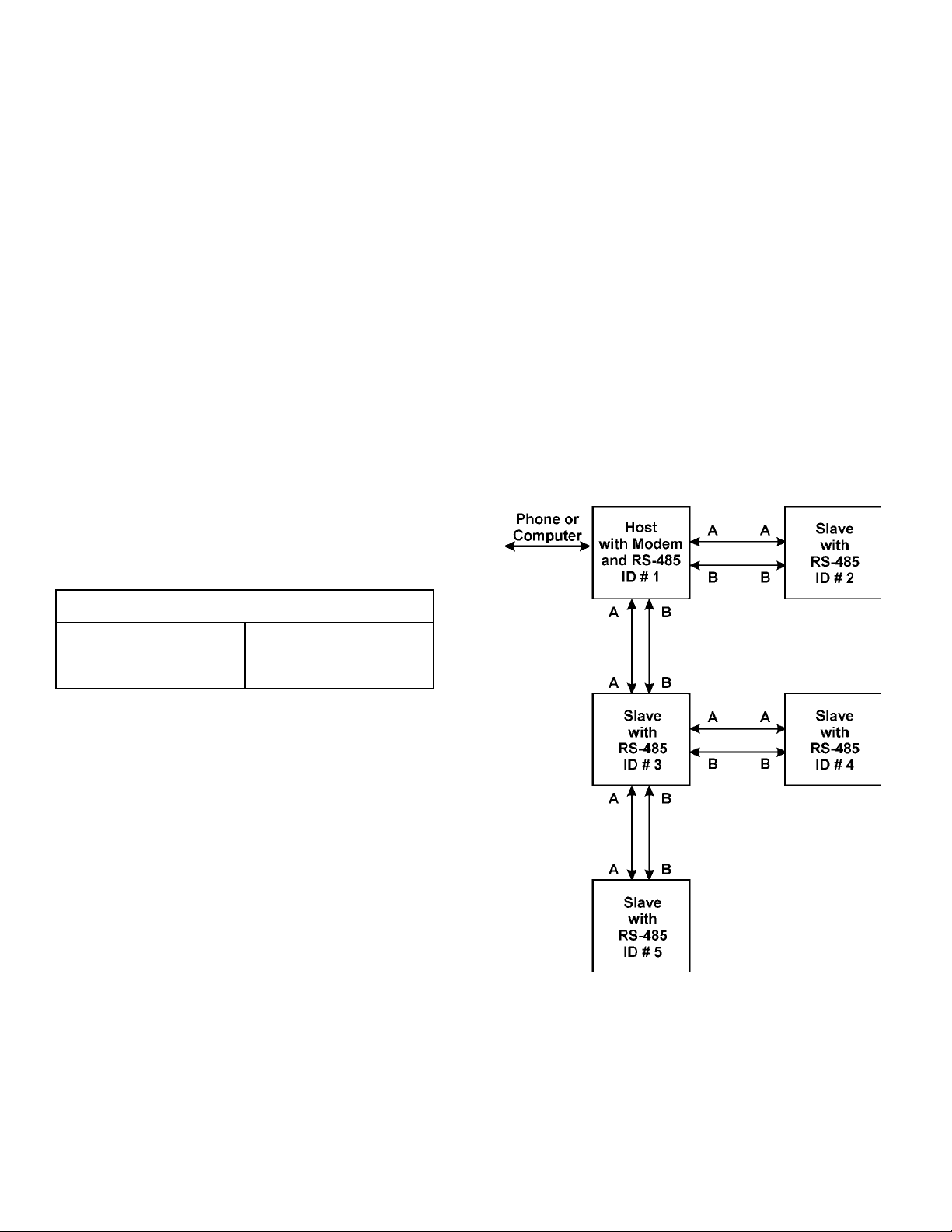
Multiple Serial Connections (Option)
Up to thirty (30) CHEMTROL® PC controllers can be
multiplexed to a single phone line or a single computer line by
using a network consisting of a host and several slaves. The
connections are made through RS485 Serial Ports (Option
RS485).
Different models of CHEMTROL® PC controllers can be mixed
and matched in a network. Each controller has its own ID
number. This number is set up through software in the
Communications Submenu 8.3.1 (see Page 30)
Ring Equivalency Number
(REN) 0.2 A
As shown in Figure 6, the host controller includes a modem
and an RS485 connection (Option REM). It is connected to the
telephone line by modem or to a computer equipped with an
RS485 communication card. The slave units need only an
RS485 connection (no modem needed) and an internal ID
number.
Any controller can be set up at any time as either host or slave
by orienting the jumper JP9 as marked on the motherboard
(Error! Reference source not found.).
The slave units must be located within 3,000 feet of the host
controller and connected with two Category 5 wires (one pair).
The RS485 terminal has four terminals, only two of which,
marked A and B, are used. Each unit must be wired A to A
and B to B for proper communications. The slave units can be
connected directly to the host unit or through any other slave
units.
CAUTION: Do not wire the connections marked 24 VDC or
GND on the RS485 terminal. This could cause
serious damage to the terminal.
Figure 6 - Multiplex Connections
MANUALPC-2010 CHAPTER II – INSTALLATION Page 12
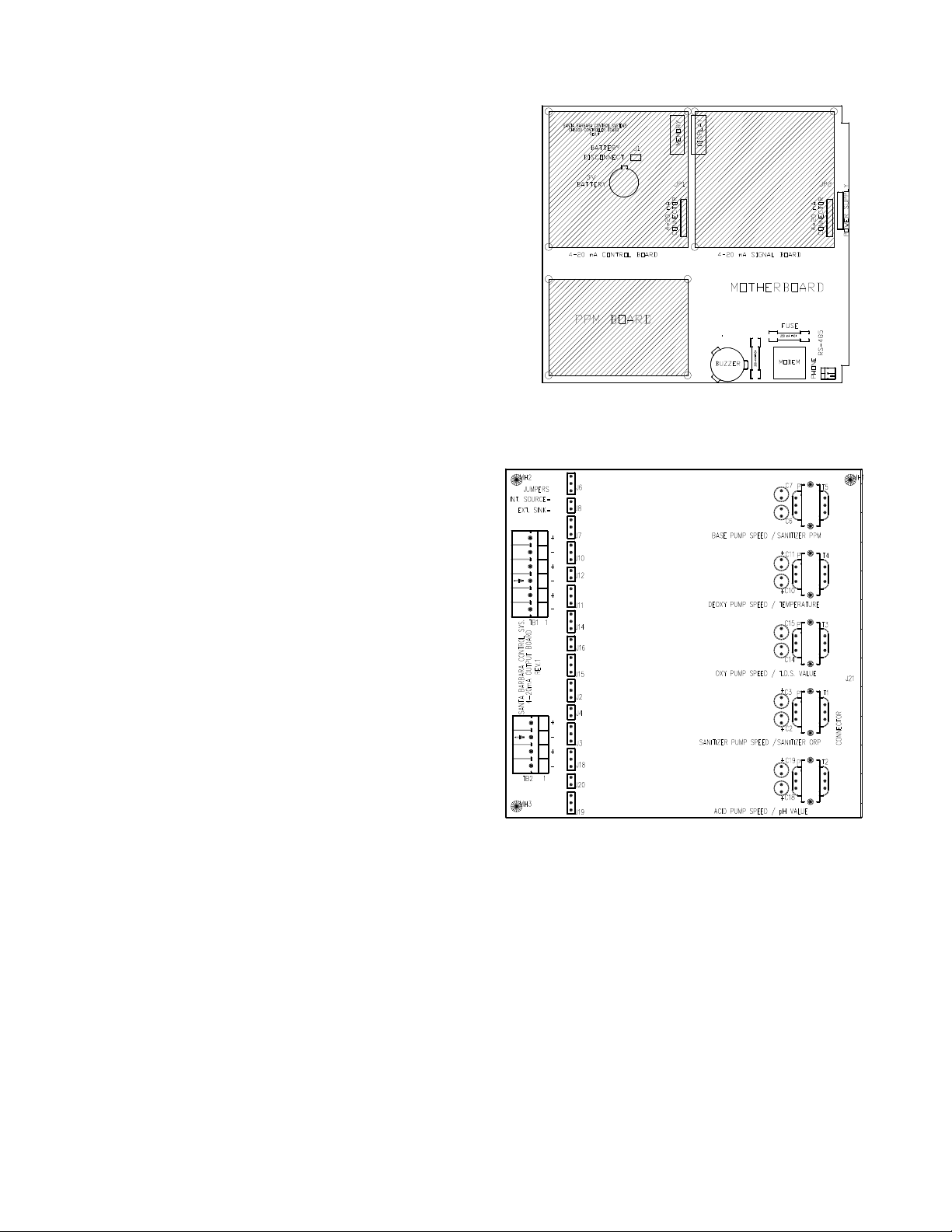
4-20 mA Converter Boards
The 4-20 mA Converter Boards are two optional piggyback
boards. They convert the digital outputs of the controller
(sensor or control outputs) into analog signals that can be used
by analog monitoring and control equipment.
The two boards are identical and are normally installed at the
factory on the motherboard before shipping, as shown in
(Figure 7). The location on the motherboard determines the
function, i.e. sensor signal or control outputs. Either one of the
boards or both can be installed, depending on requirements.
If the boards are installed properly, the controller software
automatically shows the 4-20 mA menu line in the Submenu
8.3 - Communications.
Field Installation
or field installation, turn off all power to the controller.
F
Position the converter board on top of the motherboard as
shown on Figure 7. Press the electrical connector J21 into the
socket of the motherboard marked JP1 (or JP2 depending on
option) and the three plastic standoffs fittings into the three
corresponding holes on the motherboard.
4-20 mA Connections
Figure 8 shows the connections for each Converter Board.
Determine the type of signal required by the host system.
There are two types of signals used in 4-20mA
communications, Internal source or external sink. Each
communication channel has four sets of jumpers that must be
shunted to the proper setting. (Please note that the factory
settings are generally for internal source).
The 4-20mA output signals from the board are located on the
terminal boards marked TB1 and TB2. Each channel has a +
and - indication corresponding to the markings on the board.
The 4-20mA Signal Board has five communication channels for
pH, ORP, TDS, temperature and PPM readouts. Each analog
signal requires two wires for connection to the central
monitoring system.
The 4-20mA Control Board also has five pump control
channels for acid, sanitizer, oxidizer, deoxidizer and base feed.
Each analog control signal requires two wires for connection to
the corresponding pump.
PPM Sensor Board
For new controllers, the PPM sensor board is already installed
on the lower left quadrant of the motherboard, as shown in
Error! Reference source not found..
For upgrades and retrofits, the PC board can be easily
installed on the motherboard.
At the bottom of the keypad between S15 / S16 locate the
jumper marked JP3. Insert the black pin receptacle on the
back of the PPM board into the JP3 pin connector. The two
plastic standoffs located on opposite sides of the pin
receptacle will snap into the two holes on the motherboard to
secure it.
Figure 7 - Installation of Optional Boards
Figure 8 - 4-20 mA Converter Board
MANUALPC-2010 CHAPTER II – INSTALLATION Page 13
PLUMBING
This section covers the installation of the sensors and the
connection of the chemical feeders or control valves.
All chemical injection should be done on the return line, i.e.
downstream of the sensors and pool equipment, as explained
in the Chemical Feeders section.
Installation of Sensors
Figure 9 - Sensor Installation
The CHEMTROL® PC controllers use up to nine different
sensors for measurement of water chemistry, temperature,
flow rate, pressure and water level:
- amperometric sensor for Free Chlorine,
- potentiometric sensors for pH and ORP,
- thermistor for temperature,
- conductivity sensor for Total Dissolved Solids,
- Hall effect pulse generator for flow rate,
- piezoelectric sensors for influent and effluent pressures,
- electro-optical water level sensor.
The first five sensors measure water chemistry (Free Chlorine,
ORP, pH, conductivity and temperature). These can be
mounted directly on a 2-inch main recirculation line using PVC
reducing tees Figure 9). On larger diameter lines, they must
be mounted on a ½-inch bypass line - using a Sensor Cell
Cabinet (Figure 11).
In-line Installation (2" Pipe)
n smaller installations (2 “ pipe diameter), the sensors can be
O
mounted directly on the main recirculation line between the
strainer and the pump (Figure 9).
Use only 2x2x½ in. SST reducing tees without reducers. Do
not install the sensors near an elbow or a constriction where
there might be excessive turbulence.
Install the tees on the suction side of the pump and make sure
that the tip of the sensor is oriented downward - as shown in
Figure 9 - to avoid formation of air pockets near the tip. The
sensors should be readily accessible for servicing but not
exposed to physical damage.
After inserting the sensor, be careful not to overtighten the
compression fitting as it can crush the small glass tube inside
the sensor. Make it finger tight (no wrench).
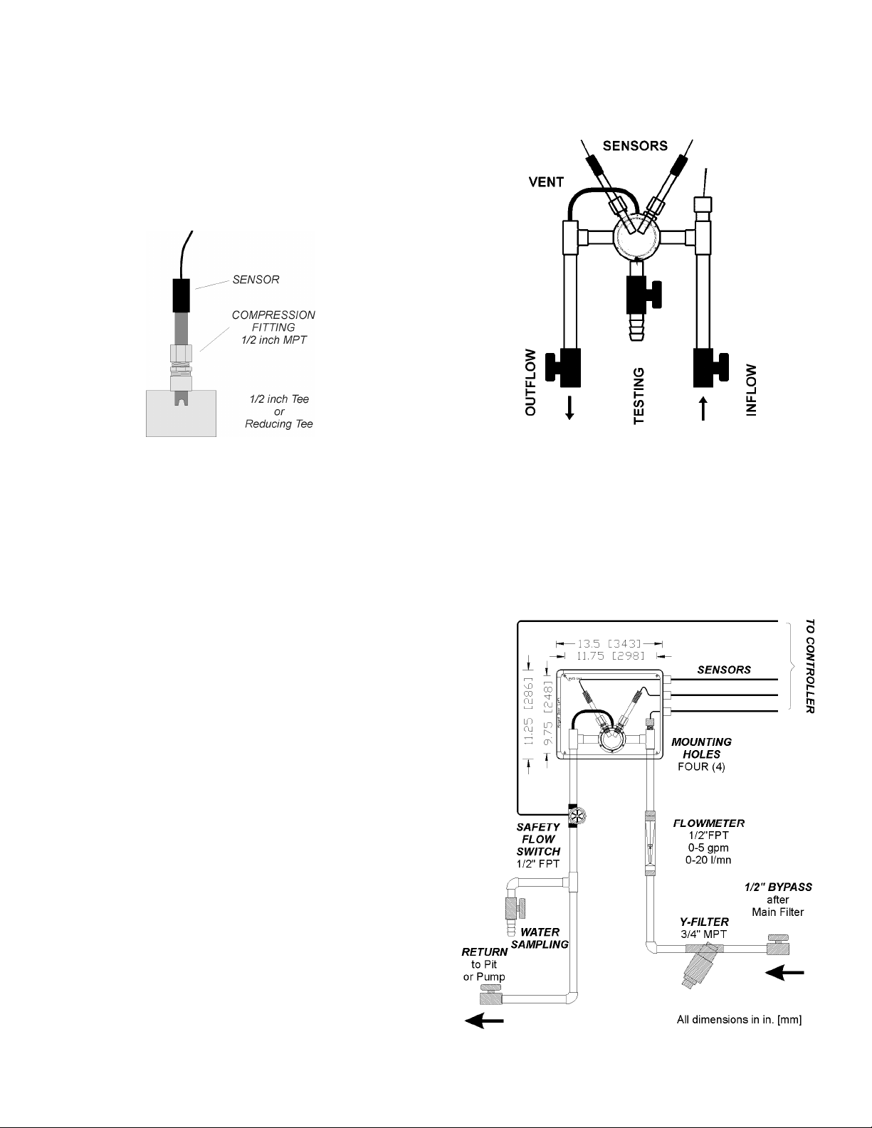
Flow Cell Assembly
Figure 10 - Flow cell Assembly
For ease of installation and maintenance, the sensors should
be mounted on the Flow Cell Assembly, as show above. It
includes a sensor cell with an air vent and a clear cover, two
compression fittings for the ORP and pH sensors, a water
sampling tap and two ball valves for controlling the water flow
in and out.
Sensor Cell Cabinet (Option)
Figure 11 - Sensor Cell Cabinet (Option)

MANUALPC-2010 CHAPTER II – INSTALLATION Page 14
For even greater ease of installation and maintenance, the
components of the bypass line assembly can be supplied in a
pre-plumbed Sensor Cell Cabinet (also called Wet Box). The
Flow Cell Assembly is mounted in a fiberglass cabinet
containing the sensor cell assembly. Also included is a Y-filter,
a flowmeter and a paddle wheel safety flow switch. Install on a
½" bypass line, as shown in Figure 11,
Make sure that the Sensor Cell Cabinet is located within 2' (60
cm) of the controller cabinet or order sensor extension cables
(see Sensor Cables). See wiring instructions in the
ELECTRICAL section and operational instructions under
WATER FLOW below.
Water Flow
Proper flow of water past the sensors is essential to obtaining
good readings. To check the water flow in the bypass line,
start the main recirculation pump. Open both the intake and
the return valves on the bypass line and read the flow rate on
the flowmeter. It should be in the middle of the range, i.e.
about 2-3 gpm (about 8 to 12 l/min). If the water flow is too
high, reduce it by closing down the valve on the RETURN
SIDE of the bypass line. If there is no water flow, replumb the
bypass line as shown on the schematic.
NOTE: The most common installation problems with bypass
line or wet box installations are caused by faulty
hydraulics.
To ensure proper water flow, make sure that the bypass line is
properly connected. The intake side should be off the pressure
side of the recirculation system, i.e. after the filter. The return
side should be to a low-pressure area - such as the vacuum
side before the recirculation pump, or downstream after the
heater, or atmospheric pressure in the pit of a vacuum sand
filter or balancing tank.
Paddle Wheel Rotary Flow Switch
The Rotary Flow Switch is a safety switch for the bypass line.
The switch contains a transducer that generates an electrical
signal proportional to the water flow. The relay trip point is
factory adjusted for a minimum flow rate of 1 gpm (about 4
l/min). (Make sure to use the flow restrictor included in
package).
CAUTION: Improper wiring will result in switch burnout
(not covered under warranty).
The black, red and white leads should be connected to the
contacts marked “BYPASS FLOW PULSER” on the terminal
board marked TB3 on the right side of the Mother Board
(Error! Reference source not found.), as indicated:
BLACK Ground
WHITE Signal
RED + 5VDC or +24 VDC
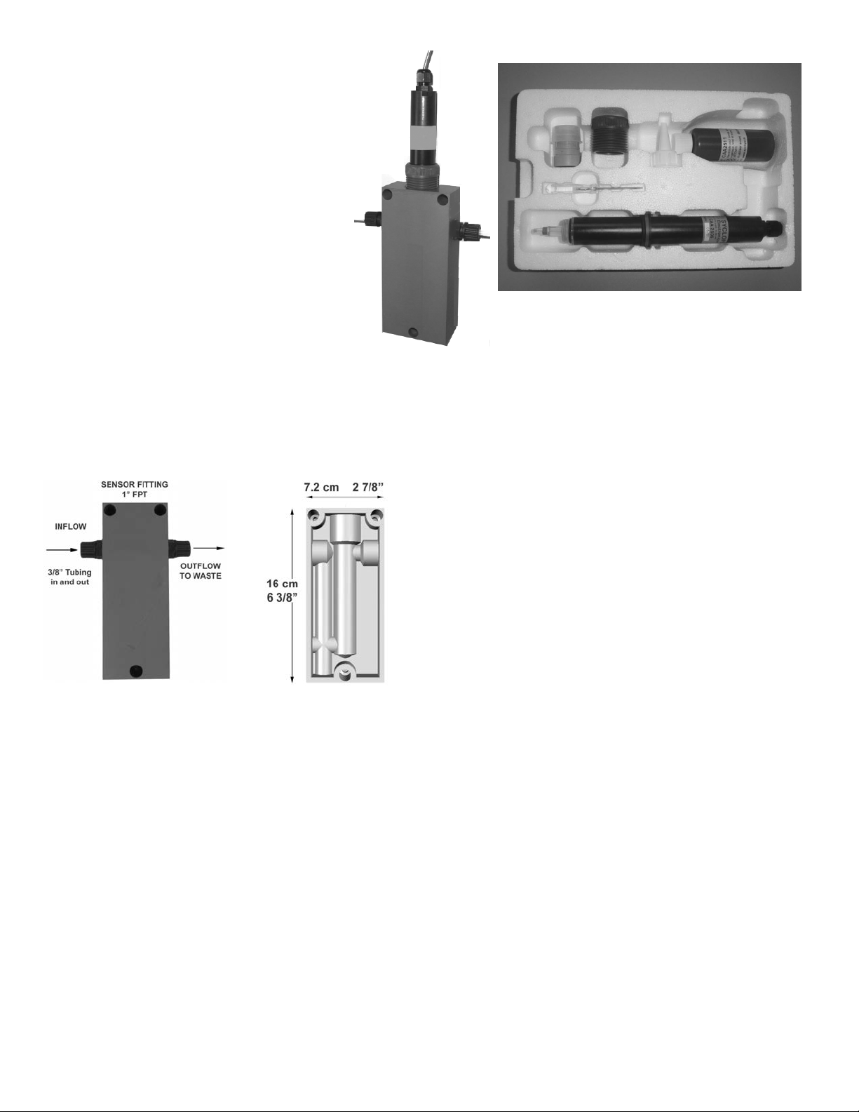
MANUALPC-2010 CHAPTER II – INSTALLATION Page 15
PPM SENSORS
The following new, improved PPM Sensors (Model
2010) are available with PC controllers:
- PPM002 for 0-2 PPM (mg/l) of Free Chlorine
- PPM010 for 0-10 PPM (mg/l) of Free Chlorine
Both use the same membrane Part Number
PPMM01
- PPM200 for 0-200 PPM (mg/l) of Free Chlorine
ith membrane part number PPMM02
w
- PPMSLT 0-10 PPM Membraneless Sensor for
electrolytic chlorine generators.
NOTES
1. These new sensors are not affected by cyanuric
acid - therefore the new CH255/265 (Version 2010) have no
GAIN FACTOR adjustment.
2. All sensors use the same flow cell PPMCLL and do not
require the plastic spacer ring.
PPM Sensor Flow Cell
Figure 12 - PPM Sensor Flow Cell
The PPM Sensor must be installed in the specially designed
flow cell for better water flow control. Install the flow cell on a
bypass line with 3/8” tubing as shown above.
Make sure that the bypass line is located after the filter and
that there is a sufficient but not excessive flow of water. The
recommended flow rate is between 20 to 100 l/h (0.1 to 0.6
gal/min.) with a best value of about 30l/h (0.2 gal/min).
SPAS
For a spa, it is recommended to increase the flow rate
sufficiently to avoid the formation of air bubbles and to install
the cell horizontally with the inflow coming in from the bottom.
PPM Sensor Installation
The new PPM Sensors are shipped in a molded foam package
containing:
- One (1) chlorine sensor with warranty serial number,
- One (1) compression fitting with O-ring,
- One (1) electrolyte cap with membrane,
- One (1) electrolyte bottle and screw-on filling tip,
- One (1) screwdriver (not needed if pre-wired).
In order to prevent serious damage to the sensor, be careful
not to touch the membrane or the electrodes. To facilitate
shipment and storage of the sensor, it is not fitted with the
electrolyte cap until ready for installation. The sensor cap must
be filled with the electrolyte solution immediately before usage
and emptied during storage.
Fill the sensor cap with the electrolyte taking care to prevent air
bubbles. Fill the cap to the bottom of the threaded section.
Thread the sensor into the cap as far as it will go while making
sure not to touch the membrane film at the bottom with your
fingers. Excess air and electrolyte may escape through the
hole below the rubber seal. Wipe any excess electrolyte with a
soft tissue. Contact your CHEMTROL
additional electrolyte.
Slide the O-ring over the sensor tip up to the compression ring.
Finally, insert the sensor with O-ring in the flow cell and make it
finger tight.
For best performance, it is recommended to change the
membrane cap and electrolyte at least once a year.
PPMSLT SENSOR
The PPMSLT sensor does not use a membrane and has a
different open-through cap that holds the electrolyte solution
around the electrodes glass shaft. Because this cap is opened
from both sides, the procedure to fill it with the necessary
electrolyte is slightly different in that you must do so with the
accompanied lid on before fully screwing that cap onto the
electrodes then finally removing that lid.
The PPMSLT sensor is the only sensor that requires cleaning
of its gold electrodes tip and you do so with the small special
abrasive cleaner the sensor is shipped with.
Figure 13 - PPM Sensor Package
(R)
dealer if you need
 Loading...