


PVC & CPVC
Fittings & Valves
Thermoplastic Flow Solutions
®
Chemtrol
®
Chemtrol® is a brand of
www.chemtrol.com
®
Thermoplastic Flow Solutions
®
Our high quality line of thermoplastic valves, fittings, and
pipe are the reason you can count on Chemtrol to fit your
industrial flow-control applications.
Chemtrol
Proven
dependability.
Chemtrol flow-control
products are unsurpassed in
performance and longevity.
With more than 60 years of
experience in industrial
thermoplastics, Chemtrol
offers dependable products
that work in the most
demanding environments.
Innovative
technology.
Great ideas flow from
Chemtrol in PVC, CPVC, PP,
and PVDF products for a
wide range of flow-control
applications.
Technical service
and sales support.
Our technical specialists
are some of the best in the
business. As part of your
team, they provide expert
advice, solve problems, and
assist you every step of the
wa y.
Our distributors, sales
professionals, and service
representatives offer ideas,
answer questions, and put
their knowledge to work
for you.
Education and
training.
We help you learn about the
benefits of thermoplastics
through excellent programs:
classes and seminars specific
to your industry, presented
at our manufacturing facility,
or product and application-
specific seminars conducted
in the field. Our high-quality
product and technical
manuals are available on
request, and a full listing of
Chemtrol products is provided
on our web site,
www.chemtrol.com
WARNING: DO NOT USE OR TEST THE PRODUCTS IN THIS CATALOG WITH COMPRESSED AIR OR OTHER GASES. Revision 1/2/2018
2
FAILURE TO FOLLOW THIS WARNING CAN RESULT IN PERSONAL INJURY OR DAMAGE TO PROPERTY.
®
Table of Contents
www.chemtrol.com
Introduction 4
Introduction to Chemtrol
Materials 5
Chemical Resistance 5
Product Line 6
Product Guide 8
Ball Valves
®
PVC & CPVC Tru-Bloc
PVC & CPVC Tru-Bloc
Model D Ball Valves 9
®
Model C Ball Valves 10
PVC & CPVC Vented (Bleach) Ball Valves 11
PVC & CPVC 3-Way Ball Valves 12
PVC Compact Economy Ball Valves 14
Butterfly Valves
PVC & CPVC Butterfly Valves, Model C 15
PVC & CPVC Butterfly Valves, Model B 16
Ball Check Valves
PVC & CPVC True Union Ball Check Valves 17
Angle & Globe Valves
PVC Angle and Y-Pattern Globe Valves 18
Lab Valves
TM
PVC Chemcock
and Calibrated-Needle Valves 19
Valve Accessories 20
PVC Schedule 80 Fittings 24
CPVC Schedule 80 Fittings 34
Reference Data 43
Standards 53
Product Specifications 54
Warranty 59
Copies of the Chemtrol publications are available for download on www.chemtrol.com.
Kynar® is a registered trademark of Arkema Inc.
WARNING: DO NOT USE OR TEST THE PRODUCTS IN THIS CATALOG WITH COMPRESSED AIR OR OTHER GASES. Revision 1/2/2018
FAILURE TO FOLLOW THIS WARNING CAN RESULT IN PERSONAL INJURY OR DAMAGE TO PROPERTY.
3
®
Introduction
Introduction to Chemtrol
With more than 60 years of experience in industrial
thermoplastics, Chemtrol offers dependable products that
work in the most demanding environments.
The premium line of quality Chemtrol
corrosion-resistant, and maintenance-free – saving you time
and money.
For specific recommendations of chemical compatibility, see
the Chem-Guide. For engineering data related to plastic piping
system design and installation and maintenance instructions,
see the Chemtrol Thermoplastic Piping Technical Manual.
All Chemtrol publications are available for download on
www.chemtrol.com in PDF format.
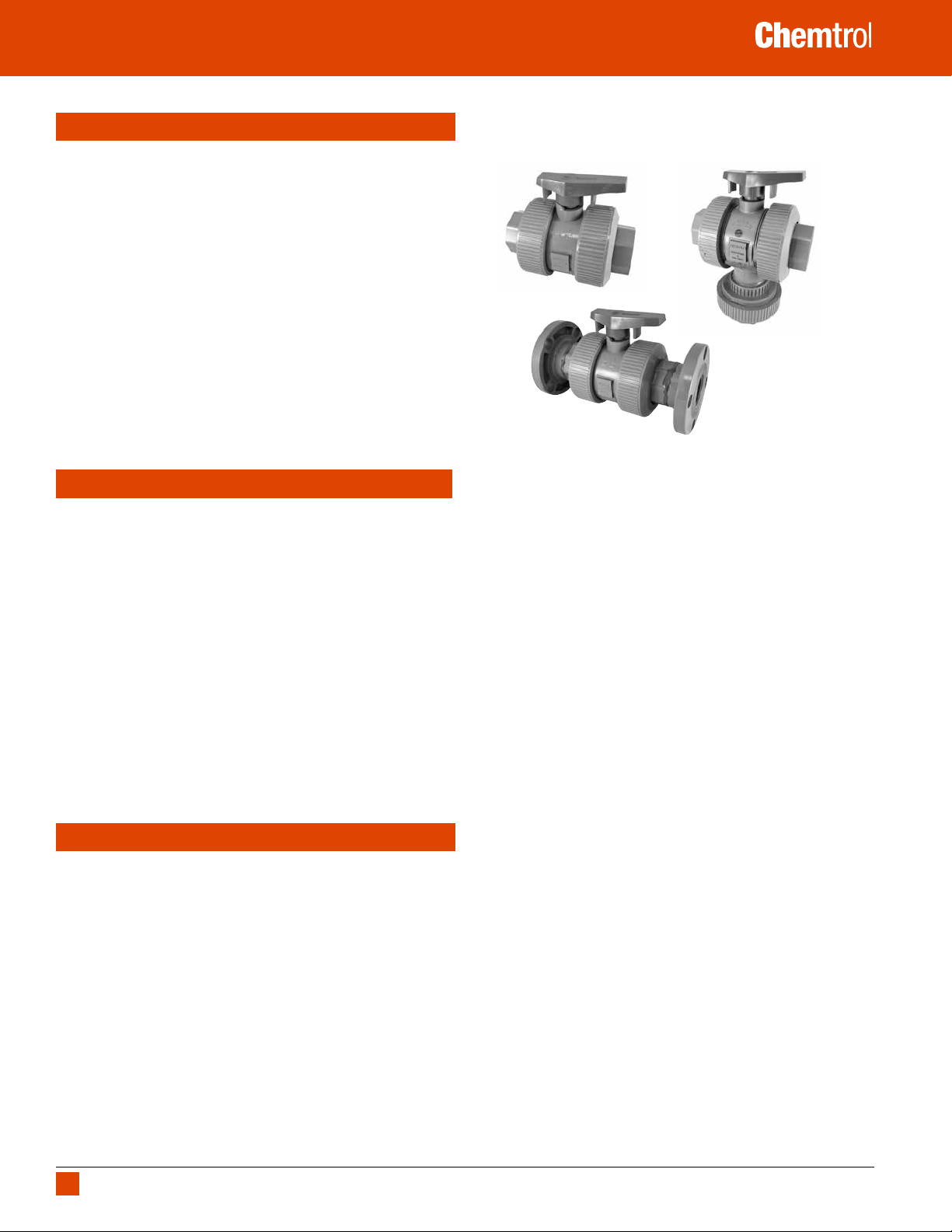
True Union Ball Valves
®
valves are lightweight,
True Union
www.chemtrol.com
True Union 3-Way
True Union Flanged
The True Union feature, a Chemtrol introduction, an exclusive Chemtrol
introduction, so revolutionized the industrial plastic valve industry that it
has become the standard followed by all major manufacturers. The purpose
of the design is to permit the valve cartridge, i.e., the body containing all
operational components, to be easily lifted from the piping system for
servicing/replacement when the union nuts are backed off. Easy repair/
replacement, interchangeability, distribution availability, technical service,
and reliable quality are the synergistic rationale many plants and original
equipment manufacturers have embraced while standardizing on Chemtrol
True Union Ball and Check Valves.
The laying length of the body and the heavy-duty modified-acme threads
in the union connections to the body have not changed in the four distinct
models’ 40-year history of the valve. This permits fouled valve replacement
with a new body cartridge, which will fit the old union nuts. No change in
piping length is required.
The distinctive orange handle indicates “open/close” and direction of flow
at a distance. And molded-in arrows on top of the handle dictate rotational
direction to personnel for easy operation within 90° stops. For applications
requiring handle removal, the D-ring stem flats indicate "open/close" and a
molded-in arrow on top of the stem indicates flow direction.
The Evolution of Chemtrol
As a result of continuous testing and improvements since the inception of
the True Union Ball Valve, three distinct model changes have occurred. The
original True Union Model A design had a seat-carrier that slid into the
smooth bore of the valve body, held in place by the external nut and end
connector. Tightening the external nut adjusted the compression of the PTFE
seat onto the ball.
The first major evolution to the True Union Ball Valve, Model B, introduced
the Tru-Bloc concept, a functional safety feature. With this design a
separate threaded retainer locked the seat-carrier into the body and
prevented the seat-carrier from being extruded out of the valve body when
the external nut was removed. This change is intended to prevent pressure
on the other side of the valve from ejecting the internal components and
fluid medium out of the open valve end and to further prevent possible
injury to persons or property.
®
Ball Valves
®
The Model C seat-carrier design was modified to include an external thread
which mated into the valve body threads, eliminating the separate retainer.
This modification also eliminated the adjustment of the seat-carrier by the
external nut and end connector, resulting in a sealing envelope that was
independent of external forces. An energized O-ring was added under the
PTFE seat that provided automatic adjustment to compensate for seat wear.
This design modification continued the Tru-Bloc feature, preventing the seat
carrier from being extruded out of the valve body when the external valve
nut was removed.
Manufactured in PVC and CPVC through 2", the current Model D ball
valve’s seat-carrier internal threads and the external union nut threads
were strengthened to provide an increased pressure rating of 250 psi at
73°F and improved the pressure ratings at higher temperatures. The end
connector design was modified to provide wrench flats. The union nut
OD was changed to provide improved gripping for strap wrenches. The
Model D design continued the sealing envelope that was independent of
external forces with an energized O-ring under the PTFE seat that provided
automatic adjustment to compensate for seat wear. The Tru-Bloc® feature
was also retained.
WARNING: DO NOT USE OR TEST THE PRODUCTS IN THIS CATALOG WITH COMPRESSED AIR OR OTHER GASES. Revision 1/2/2018
4
FAILURE TO FOLLOW THIS WARNING CAN RESULT IN PERSONAL INJURY OR DAMAGE TO PROPERTY.

®
Introduction
Materials
PVC
(Polyvinyl Chloride) PVC conforming to ASTM D1784, Classification 12454, formerly
designated Type I, Grade 1, is the most frequently specified of all thermoplastic piping
materials. It has been used successfully for more than 55 years in such diverse areas as
chemical processing, industrial plating, chemical drainage, fresh and wastewater treatment,
chilled and tower cooling water, deionized water manufacture and distribution, and irrigation
sprinkler systems. PVC is characterized by high physical properties and resistance to chemical
attack by strong acids and other oxidizers, alkalis, salt solutions, some organic chemical
solutions, and many other chemicals. However, it is attacked by non-ionic surfactants,
some vegetable oils (e.g., peanut), and many organic chemicals such as polar solvents (e.g.,
ketones), aromatics (i.e., benzene ring structure), and chlorinated hydrocarbons. The maximum
service temperature of PVC is 140°F. With a design stress of 2,000 psi at 73°F, the long-term
hydrostatic strength of PVC is as high as any of the major thermoplastic materials being used
for solid piping systems. PVC is joined by solvent cementing, threading, or flanging.
CPVC (Corzan®)
(Chlorinated Polyvinyl Chloride) CPVC conforming to ASTM D1784, Classification
23447, is a resin created by the post-chlorination of a PVC polymer. The material’s resistance
to chemical attack is almost identical to that of PVC. And the physical properties of CPVC
are very similar to those of PVC at 73°F, but the additional chlorine in the CPVC polymer
extends its maximum service temperature to 210°F. For example, the design stress for CPVC
is 2,000 psi at 73°F, identical to that of PVC. But its strength is only reduced to 500 psi at
180°F, as compared to 440 psi for PVC at 140°F. For more than 35 years, CPVC has proven to
be an excellent material for hot corrosive liquids, hot and cold water distribution, and similar
applications above the useful temperature range for PVC. CPVC may even be chosen over PVC
in the 110°F to 140°F temperature range because its higher strength-at-temperature, requiring
less frequent piping supports, can translate to a more favorable overall installed cost than
PVC. CPVC is joined by solvent cementing, threading, or flanging.
PVDF (Kynar®)
(Polyvinylidene Fluoride) PVDF homopolymer conforming to ASTM D3222, Type I,
Grade 2, is a tough, abrasion-resistant fluorocarbon material that has a design stress of
1,360 psi at 73°F and a maximum service temperature of 280°F. It has versatile chemical
resistance to salts, strong acids, dilute bases, and many organic solvents, such as the
aromatics (i.e., benzene ring structure), the aliphatics (i.e., paraffin, olefin, and acetylene
hydrocarbons), and the chlorinated groups. And PVDF is ideally suited for handling wet or dry
chlorine, bromine, and other halogens. However strong bases and some organic chemicals
such as polar solvents (e.g., ketones) and esters attack it. No other solid thermoplastic
piping material can approach the combined strength, working temperature, and chemical
resistance characteristics of PVDF. It is joined by the thermo-sealing socket fusion process,
threading, or flanging.
PVDF, absent of any color pigment, is transparent to ultraviolet light. So while PVDF is one
of the few plastic materials that is not degraded by UV radiation, exposure of the fluid
medium inside a piping system to direct sunlight can frequently adversely affect its stability.
Therefore, all PVDF piping components that Chemtrol produces for general chemical service,
contain an FDA-approved red pigment to mask the penetration of UV rays.
®
Natural Kynar
of metallic ions and foreign organic compounds. And since the resin does not require
processing or other external additives to aid manufacturing or long-term stability, the hardpolish surface of components will remain intact, so that piping systems will not release
particulate to the fluid medium. Further, there will be no surface micropores to encourage
biological growth. Natural Kynar
and chemical services, such as electronics, pharmaceuticals, and processed foods and
beverages.
PVDF Type I (polymerized in emulsion) homopolymer is notably free
®
PVDF systems are intended for ultra high pure water
www.chemtrol.com
PP
(Polypropylene) PP as specified by ASTM D4101, is a member of the polyolefin family
of pure hydrocarbon plastics. Although PP has half the strength of PVC and CPVC, with a
design stress of 1,000 psi at 73°F, it may have the most versatile chemical resistance of
the thermoplastic materials identified as the sentinels of industrial piping. Consider the
fact that there are no known solvents for PP. As a result, it has been the material of choice
for drainage of mixed industrial chemicals for over 40 years. As pressure piping, PP has no
peers for concentrated acetic acid or hydroxides. It is also suitable for milder solutions of
most acids, alkalis, salts, and many organic chemicals, including solvents. The nemeses
for PP are strong oxidizers, such as the hypochlorites and higher concentrations of sulfuric,
nitric, and hydrofluoric acids. They are Environmental Stress Cracking (ESC) agents for PP,
meaning that time-to-failure is a function of the combined variables of concentration and
temperature of the fluid and stress. Although PP is not recommended for some organic
chemicals, such as polar and chlorinated solvents and the aromatics, the concern is
permeation through rather than catastrophic damage of the molecular chain.
Black PP used in Chemtrol products is formulated with a minimum 2.5% carbon black. The
plastic pipe industry recognizes PP formulated with this level of carbon black as suitable for
long-term outdoor service.
®
Chem-Pure
because of its extremely low content of metals, organic compounds other than naturally
pure propylene, and free ions. No pigments or other adulterants (natural) are added to
the plastic resin. Chem-Pure
Chem-Pure systems are intended as an economic alternative to the ultra high purity PVDF
systems typically found in the highly sophisticated electronic semi-conductor industry.
Natural PP utilized to produce Chemtrol® piping products was selected
®
systems are intended for high purity chemicals or DI water.
FKM
(Fluoroelastomer) FKM is compatible with a broad spectrum of chemicals. Because
of this extensive chemical compatibility, spanning wide ranges of concentration and
temperature, FKM has gained wide acceptance as a material of construction for valve
o-rings and seats. These fluoroelastomers can be used in most applications involving
mineral acids (with the exception of HCl), salt solutions, chlorinated hydrocarbons, and
petroleum oils. FKM is not recommended for most strong alkali solutions.
EPDM
(Ethylene-propylene-diene monomer) EPDM is a terpolymer elastomer that has good
abrasion and tear resistance and offers excellent chemical resistance to a variety of salt,
acidic, and organic chemical solutions. It is the best material for most alkali solutions and
hydrochloric acid, but is not recommended for applications involving petroleum oils or
most strong acids.
PTFE
(Polytetrafluoroethylene) PTFE has outstanding resistance to chemical attack by most
chemicals and solvents. PTFE has a temperature rating of -200°F to +500°F. It is a selflubricating material used as a seat and/or bearing material in most Chemtrol
®
valves.
Chemical Resistance
While thermoplastic piping systems are useful in general water service because they are
light-weight, easy to install, and cost-effective, they excel in corrosive environments, such
as water and wastewater treatment, food and pharmaceuticals, chemical processing,
mining, power plants, oil refineries and more. Choosing the proper material for corrosive
fluids can be handled by consulting the NIBCO Chem-Guide and understanding the effect
that temperature will have upon plastic materials’ strength.
Chemical resistance is the ability for a particular plastic material to maintain properties in
contact with a chemical. To ensure comprehensive chemical compatibility, a piping system
must take into consideration the chemical resistance of all system components, including,
but not limited to, plastic components, solvent cements or thread pastes (if applicable),
elastomeric seals, all valve components and lubricants. Testing under field conditions may
be the best way to ensure selected materials will work in a particular application.
Kynar® is a registered trademark of Arkema Inc.
®
is a registered trademark of The Lubrizol Corporation.
Corzan
WARNING: DO NOT USE OR TEST THE PRODUCTS IN THIS CATALOG WITH COMPRESSED AIR OR OTHER GASES. Revision 1/2/2018
FAILURE TO FOLLOW THIS WARNING CAN RESULT IN PERSONAL INJURY OR DAMAGE TO PROPERTY.
5
®
Introduction
Typical Applications
Joining Methods
Max. Service Temperature
Polyvinyl
Chloride (PVC)
Chemical processing, industrial plating, chilled
water distribution, chemical drainage, and
irrigation systems
Solvent cementing, threading, or flanging
140° F/60° C
www.chemtrol.com
Chlorinated
Polyvinyl Chloride
®
(Corzan
Systems for hot corrosive liquids, hot and cold
water distribution, chemical processing, industrial
plating, deionized water lines, chemical drainage,
waste water treatment systems, and similar
applications above the temperature range of PVC
210° F/99° C
CPVC)
Fittings Schedule 80
Large diameter
Valves Tru-Bloc
Tru-Bloc
Butterfly valves*
Multiport valves*
Specialty valves
®
/True Union
ball valves*
®
/True Union
ball check valves
Socket– 1/4" through 12"
Threaded– 1/4" through 4"
10" and 12" couplings, tees, 90° and 45° elbows,
reducer bushings, and Van Stone flanges
1/2" through 6" socket, threaded, and flanged
connections
1/2" through 4" with socket, threaded, or
flanged ends
EPDM and FKM liner 2" through 10" Model C
True Union 3-way/3-position; 1/2" through 2"
with socket, threaded, or flanged ends
Angle and Y pattern: 1/4" through 1" threaded
Needle and Chemcock
TM
: 1/4" threaded
Socket– 1/4" through 12"
Threaded– 1/4" through 4"
10" and 12" couplings, tees, 90° and
45° elbows, reducer bushings
1/2" through 6" socket, threaded, and flanged
connections
1/2" through 4" with socket, threaded, or
flanged ends
EPDM and FKM liner 2" through 10" Model C, 3"
only Model B
True Union 3-way/3-position; 1/2" through 2"
with socket, threaded, or flanged ends
Pipe
*For pneumatic or electric actuation.
Refer to Chemtrol Technical Manuals for pressure ratings at various temperatures.
Kynar® is a registered trademark of Arkema Inc.
®
is a registered trademark of The Lubrizol Corporation.
Corzan
WARNING: DO NOT USE OR TEST THE PRODUCTS IN THIS CATALOG WITH COMPRESSED AIR OR OTHER GASES. Revision 1/2/2018
6
FAILURE TO FOLLOW THIS WARNING CAN RESULT IN PERSONAL INJURY OR DAMAGE TO PROPERTY.
www.chemtrol.com
®
Polypropylene
(PP)
Black Polypropylene:
Clean chemical processes,
hot corrosive liquids,
industrial plating, waste
treatment systems
180° F/82° C 180° F/82° C
IPS socket type–
1/2" through 6"
Threaded–
1/2" through 4"
Natural Polypropylene:
Deionized water systems,
clean chemical processes,
pharmaceutical operations,
food processing
Socket heat fusion, threading, or flanging
IPS socket type–
1/2" through 4"
Threaded–
1/2" through 4"
Polyvinylidene Fluoride
®
(Kynar
Red Kynar
Protects fluid medium from
UV exposure, is an excellent
material for general
industrial applications,
especially outdoor
installations.
280° F/138° C
IPS socket type–
1/2" through 6"
Threaded–
1/2" through 2"
PVDF)
®
PVDF:
®
Natural Kynar
(unpigmented) PVDF:
Ideal for industries
such as electronics,
pharmaceuticals,
and processed foods
or beverages.
280° F/138° C
IPS socket type–
1/2" through 6"
Threaded–
1/2" through 2"
1/2" through 4" with
socket, threaded, or
flanged ends
1/2" through 4" with socket,
threaded, or flanged ends
1/2" through 6" schedule 80 wall thicknesses
1/2" through 4" with
socket ends
1/2" through 2" with
socket ends
1/2" through 4" with
socket, threaded, or
flanged ends
1/2" through 4" with socket,
threaded, or flanged ends
1/2" through 6" schedule 80 wall thicknesses
1/2" through 4" with
socket, threaded, or
flanged ends
1/2" through 4" with socket,
threaded, or flanged ends
Kynar® is a registered trademark of Arkema Inc.
WARNING: DO NOT USE OR TEST THE PRODUCTS IN THIS CATALOG WITH COMPRESSED AIR OR OTHER GASES. Revision 1/2/2018
FAILURE TO FOLLOW THIS WARNING CAN RESULT IN PERSONAL INJURY OR DAMAGE TO PROPERTY.
7
®
Product Guide – Valves
Key to Chemtrol Valve Figure Number System
X XX XX - X - XX - SIZE
1 2 3 4 5 6
1 End Configurations
S Socket
F Flanged
T Threaded (female)
M Threaded (male)
A Hose x Male Threaded
W Wafer Style Butterfly
U Universal (socket and threaded)
2 Body Material
45 PVC Schedule 80
51 CPVC Schedule 80
61 Black Polypropylene (PP)
62 Chem-Pure® Natural Polypropylene (PP)
65 Red Kynar® PVDF
66 Natural Kynar® PVDF
3 Types of Valves
AC Angle
BC Ball Check
BF Butterfly (Model B)
BG Butterfly (Model C)
CC ChemcockTM
CN Needle
D2 Diverter (3-Way, 2-Position)
FV Ball Foot
M3 Multiport (3-Way, 3 Position)
TB Tru-Bloc® True Union Ball Valve
YP Y-Pattern
www.chemtrol.com
4 O-Ring Material
E EPDM
V FKM
5 Operating Mechanisms
NO None
LH Lever Handle, Manual
RH Round Safety Handle, Manual
GO Gear Operator, Manual
6 Size
State Valve Size
Kynar® is a registered trademark of Arkema Inc.
WARNING: DO NOT USE OR TEST THE PRODUCTS IN THIS CATALOG WITH COMPRESSED AIR OR OTHER GASES. Revision 1/2/2018
8
FAILURE TO FOLLOW THIS WARNING CAN RESULT IN PERSONAL INJURY OR DAMAGE TO PROPERTY.
®
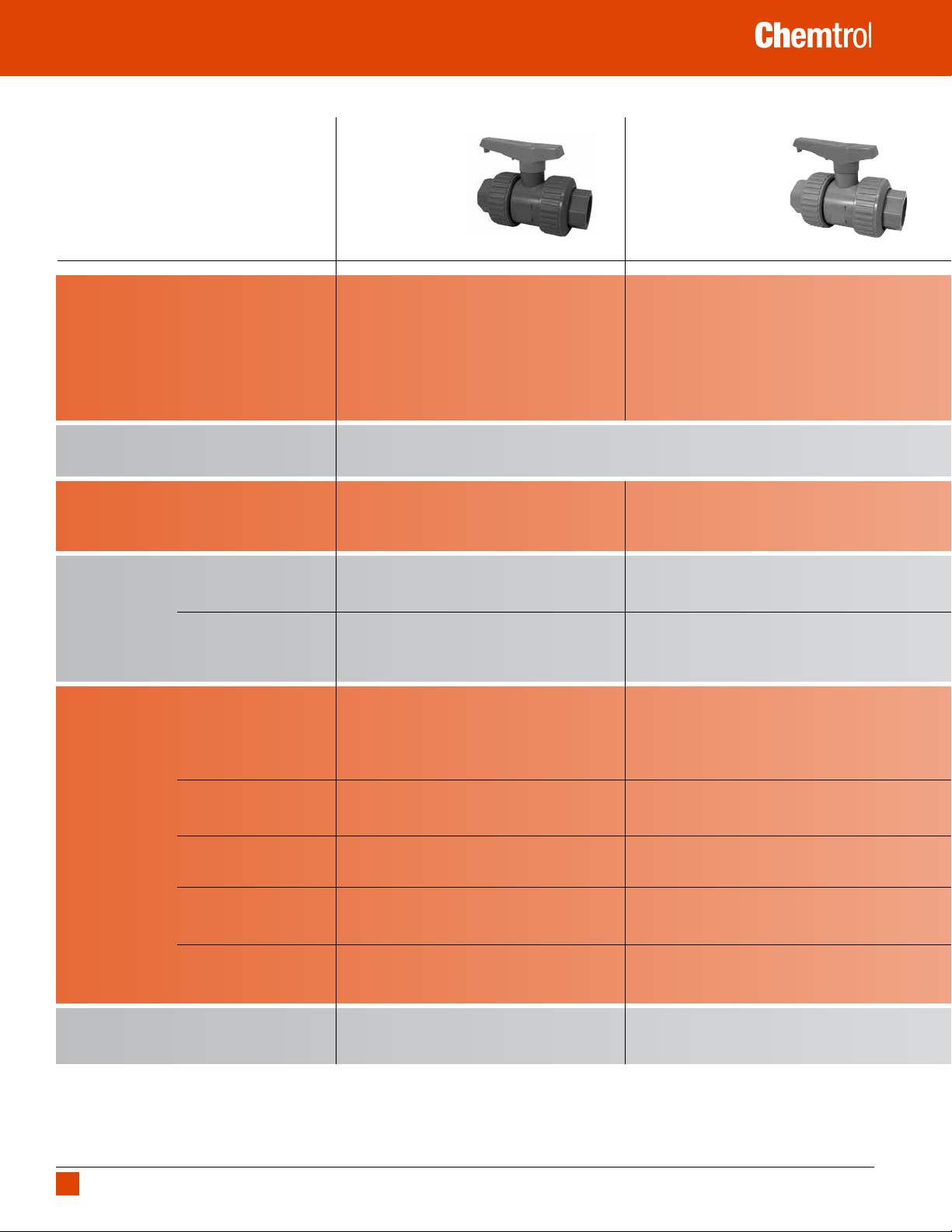
Product Guide – Ball Valves
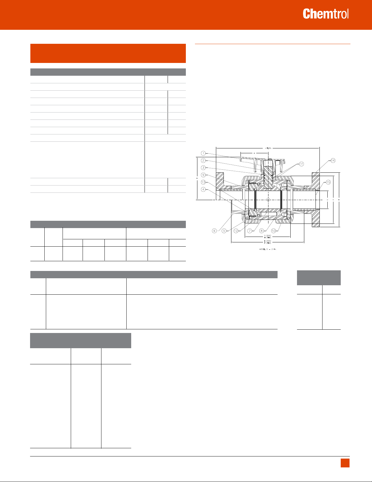
PVC and CPVC Tru-Bloc® True Union Ball Valve,
Model D
Construction Materials
1
Components
1. Handle Orange PVC
2. Stem PVC CPVC
3. Body PVC CPVC
4. Seat-Carrier PVC CPVC
5. Union Nut PVC CPVC
6. End Connector PVC CPVC
7. Ball PVC CPVC
8. Seat
9. O-Ring
10. O-Ring
11. O-Ring
12. O-Ring
13. O-Ring
14. Flange – 2 ea. Socket-End PVC CPVC
15. Plain-End Nipple; 2 ea. Spg x Spg PVC CPVC
1 All components except valve bodies are available as replacement parts.
2 Each replacement PTFE seat kit contains two seats.
3 Each replacement O-ring kit contains all the O-rings required to refurbish a particular size True
Union Ball or Check Valve (regardless of model or style), or a minimum of two pipe unions.
PVC CPVC
2
; (2 ea.) PTFE
3
– Seat-Carrier; End Seal
3
– Body; End Seal
3
– Stem; OD Seal FKM or EPDM
3
– Seat-Carrier; OD Seal
3
– Seat-Carrier; Seat Energizer
www.chemtrol.com
Features
• Rated at 250 psi with non-shock water service at 73°F
• Corzan® HP CPVC rated at 130 psi at 180°F, see chart in Reference
Data section for maximum service temperature.
• Retains laying length of previous models, full interchangeable
cartridge, nuts and end connectors
• Designed, with an energizer O-ring beneath the PTFE seat, Model D
and C valves automatically adjust for seat wear.
• Full-port design produces minimum flow restriction with the lowest
possible pressure-drop
• Improved union nut grip style and flats on end connectors
• Universal product includes socket and threaded end connections
• Ergonomic handle with built-in carrier wrench
• Valves are manufactured and assembled without exposure to silicone
compounds. Silicone-free lubricant is used to assemble all ball valves.
Chemtrol Figure Number
Elasto-
Valve meric
Style Trim Soc. Thd. Flgd. Soc. Thd.
U/TB FKM U45TB-V* U45TB-V* F45TB-V U51TB-V* U51TB-V* F51TB-V
T
EPDM U45TB-E* U45TB-E* F45TB-E U51TB-E* U51TB-E* F51TB-E
* As original equipment, 1/2" - 2" True Union Tru-Bloc valve models are supplied with universal connectors (i.e., a set of both socket and thread end connectors).
Dimensions–Weights–Flow Coefficients
Valve A
1
B C D K E F G H J PVC Approx.2 CPVC Approx.
Size Flgd. Soc. Thd. Soc. Thd. Flgd. Wt. Lbs. Wt. Lbs.
1/2 2.07 2.16 1.82 .50 3.50 4.20 4.10 2.42 2.44 6.30 0.350 0.370
3/4 2.74 2.90 2.36 .75 3.88 5.02 4.62 3.02 3.05 7.34 0.690 0.730
1 2.74 3.07 2.73 1.00 4.26 5.47 5.32 3.22 3.40 8.17 0.960 1.000
1 1/4 2.62 3.91 4.07 1.25 4.62 6.53 6.07 4.01 4.06 9.41 2.155 2.255
1 1/2 2.62 3.91 4.07 1.50 5.00 6.89 6.23 4.10 4.18 10.05 2.190 2.315
2 3.12 4.71 5.23 2.00 6.00 8.04 7.39 5.01 5.19 11.44 4.410 4.670
Maximum Non-Shock Pressure Ratings (psi)
vs. Temperaturets
"Operating
PVC CPVC
1 Handle is not symmetrical about centerline. Dimensions shown represent the
longest operational radius. The handle position is correctly shown for the
1/2" - 3" True Union valve style.
2 Weight for 1/2" - 2" TU figures includes both sets of end connectors.
values computed for basic valve laying lengths (G).
3 C
V
Flgd.
Fluid Flow
2
Coefficient
Valve Size C
1/2 6.4
3/4 38.7
1 58.2
1 1/4 61.7
1 1/2 117.4
2 178.4
Temperature(F)" PVC CPVC
73 250 250
80 250 250
90 240 250
100 180 250
110 140 225
120 115 180
130 80 160
140 60 140
150 NR 115
160 NR 95
170 NR 80
180 NR 70
190 NR 60
200 NR 50
210 NR NR
Corzan® is a registered trademark of The Lubrizol Corporation.
WARNING: DO NOT USE OR TEST THE PRODUCTS IN THIS CATALOG WITH COMPRESSED AIR OR OTHER GASES. Revision 1/2/2018
FAILURE TO FOLLOW THIS WARNING CAN RESULT IN PERSONAL INJURY OR DAMAGE TO PROPERTY.
3
TU
V
9
®
Product Guide – Ball Valves
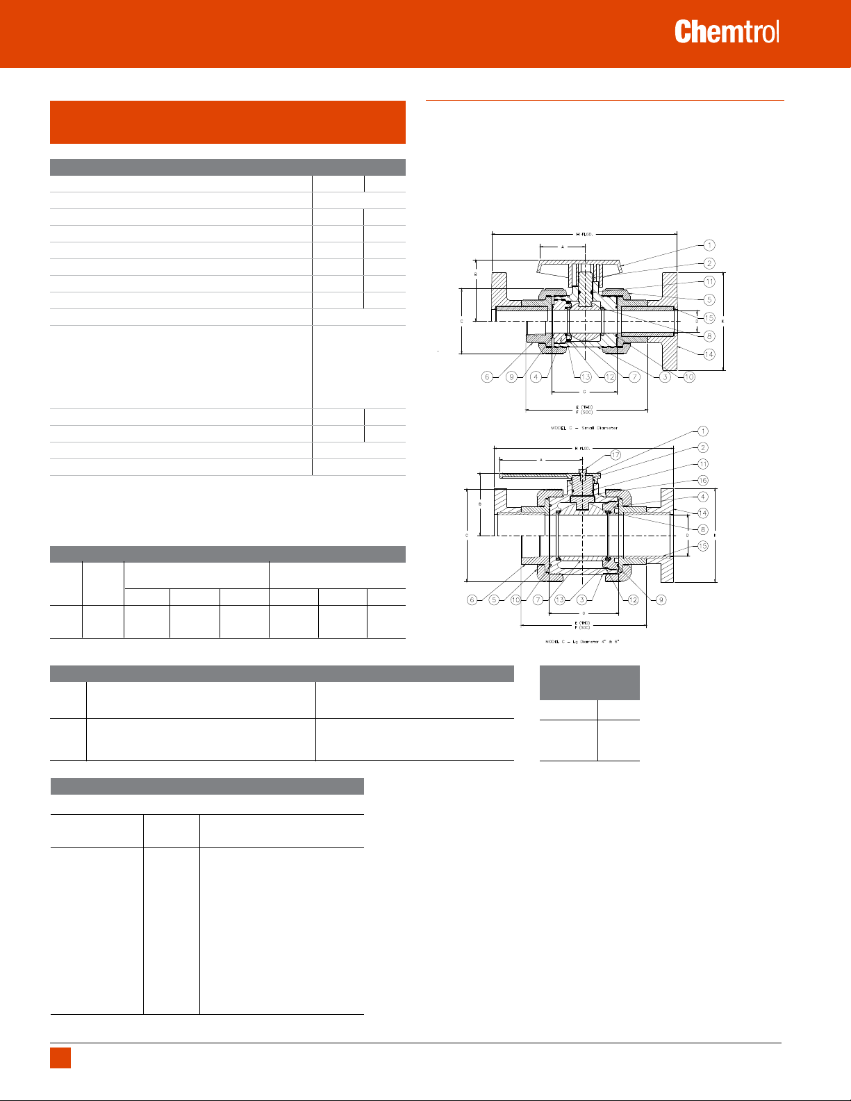
PVC and CPVC Tru-Bloc® True Union Ball Valve,
Model C
Construction Materials
1
Components
1. Handle
2. Stem PVC CPVC
3. Body PVC CPVC
4. Seat-Carrier PVC CPVC
5. Union Nut PVC CPVC
6. End Connector PVC CPVC
7. Ball PVC CPVC
8. Seat
9. O-Ring
10. O-Ring
11. O-Ring
12. O-Ring
13. O-Ring
14. Flange – 2 ea. Socket-End PVC CPVC
15. Plain-End Nipple; 2 ea. Spg x Spg PVC CPVC
16. Stem; Friction Washer (4" & 6" Only) PTFE
17. Handle Bolt (4" & 6" Only) PVC
1 All components except valve bodies are available as replacement parts.
2 Each replacement PTFE seat kit contains two seats.
3 Each replacement O-ring kit contains all the O-rings required to refurbish a particular size True
Union Ball or Check Valve (regardless of model or style), or a minimum of two pipe unions.
PVC CPVC
Orange PVC
2
; (2 ea.) PTFE
3
– Seat-Carrier; End Seal
3
– Body; End Seal
3
– Stem; OD Seal FKM or EPDM
3
– Seat-Carrier; OD Seal
3
– Seat-Carrier; Seat Energizer
www.chemtrol.com
Features
• Rated at 150 psi with non-shock water service at 73 °F.
• Designed with an energizer O-ring beneath the PTFE seat, Model D and C
valves automatically adjust for seat wear.
• Full-port design produces minimum flow restriction with the lowest
possible pressure-drop. 6" ball valve is reduced port.
• Valves are manufactured and assembled without exposure to silicone
compounds. Silicone-free lubricant is used to assemble all ball valves.
Chemtrol Figure Number
Elasto-
Valve meric
Style Trim Soc. Thd.
U/TB FKM S45TB-V T45TB-V F45TB-V S51TB-V T51TB-V F51TB-V
T
EPDM S45TB-E T45TB-E F45TB-E S51TB-E T51TB-E F51TB-E
* Thread end connections are not available for 6" valves.
PVC CPVC
* Flgd. Soc. Thd.*
Flgd.
Dimensions–Weights–Flow Coefficients
Valve A
1
B C D N P E F G H Approx.
Size Thd. Soc. Soc. Flgd. Wt. Lbs.
3 4.00 5.59 7.18 3.00 7.42 7.50 10.39 10.39 6.58 14.63 11.25
4 8.00 6.05 8.78 4.00 8.52 9.00 12.22 12.22 7.66 17.63 17.68
4
8.00 6.05 8.78 4.00 11.90 11.05 NA 30.22 24.16 24.08 29.25
6
Maximum Non-Shock Pressure Ratings (psi) vs. Temperature
"Maximum Operating Pressure (psi) vs. Temperature"
"Operating
Temperature (F)" PVC CPVC
100 150 150
110 135 140
1 Handle is not symmetrical about center line. Dimensions shown represent the longest operational radius.
The handle position is correctly shown for the 3" True Union valve style, but the position must be rotated
180° from that shown for the 4" - 6" True Unions.
2 Weight includes socket end connections only for 3" - 6" sizes. The material represented is PVC in all cases.
values computed for basic valve laying lengths (G).
3 C
V
4 The 6" ball valve is a Venturi design derived from the 4" valve: a 4" end connector and a 6"
coupling are connected by a 6" x 4" Venturied reducer, with a union nut captured within the
assembly. Threaded end connection not available.
120 110 130
130 75 120
140 50 110
150 N.R. 100
160 N.R. 90
170 N.R. 80
180 N.R. 70
190 N.R. 60
200 N.R. 50
250 N.R. N.R.
280 N.R. N.R.
N.R. - Not recommended
Fluid Flow
2
Coefficient
Valve Size C
3
TU
V
3 1348
4 2602
4
6
2602
WARNING: DO NOT USE OR TEST THE PRODUCTS IN THIS CATALOG WITH COMPRESSED AIR OR OTHER GASES. Revision 1/2/2018
10
FAILURE TO FOLLOW THIS WARNING CAN RESULT IN PERSONAL INJURY OR DAMAGE TO PROPERTY.
®
Product Guide – Ball Valves
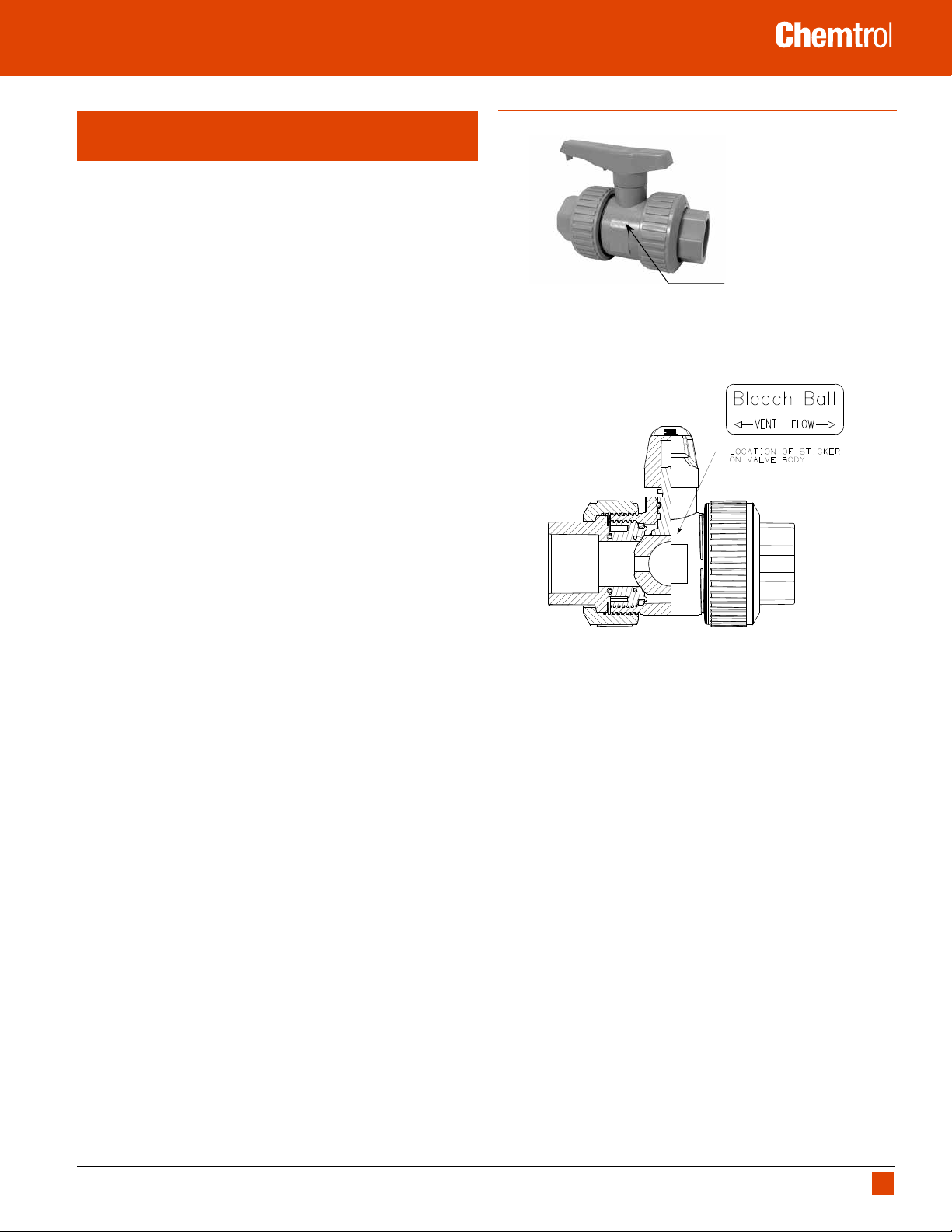
PVC and CPVC Tru-Bloc® True Union Vented
(Bleach) Ball Valve, Model D
The Problem
Sodium hypochlorite, used in water treatment, aquatic centers, and paper
and textile applications, can become trapped in the body cavity of a closed
ball valve and create conditions that may result in damage to the valve or
system as a result of unstable chemical decomposition.
The Chemtrol Solution
The Vented Ball Valve is a special factory modification to a PVC or CPVC
True Union Ball Valve that effectively vents sodium hypochlorite out-gassing
to the pressure port. In addition, the inner valve surfaces are kept constantly
wetted to ensure problem-free use of the ball valves in bleach transfer and
injection applications.
Background
In the search for a safer alternative to chlorine vacuum gas injection, fresh
and wastewater treatment, paper and textile plants, and aquatic centers are
converting to the use of sodium hypochlorite as a disinfectant or bleaching
agent. A high pH level characterizes commercial bleach, which consists of
a nominal 15% solution of sodium hypochlorite along with approximately
1-2% of sodium hydroxide to act as a chemical stabilizer. Known as a
good oxidizer, the solution has been found to cause stress cracking in
polyethylene and polypropylene materials. And metallic materials react,
causing rapid decomposition of the “hypo.” However, PVC and CPVC, with
fluorocarbon rubber (FKM) seals, have been successfully used for years to
handle this aggressive chemical solution.
www.chemtrol.com
Permanent Bleach
And Vent/Flow
Directional Marking
Some system design considerations are important, though. Heat, time, and
positive ions are enemies of bleach stability. When a ball valve is closed in
periods of inactivity, the bleach will decompose over time liberating oxygen
gas. The decomposition rate is increased by heat absorbed from sun shining
on exposed piping, or by reaction heat resulting from debris trapped in a ball
valve body between the ball and its seats. Gas pressure may slowly build in
the closed valve cavity, or quite rapidly in the reactive case. Such conditions
may result in damage to the valve or system.
Also, evaporation of sodium hypochlorite in the ball cavity can lead to the
formation of crystalline residue that eventually embeds in the PTFE seats of
a ball valve and significantly raises the turning torque due to excessive wear
on the ball by fouled seats. Such conditions may result in a broken valve
stem, frozen valve ball, or other damage to the valve or system.
The Chemtrol
hypochlorite transfer and injection applications. Our unique factoryassembled bleach ball valve has effectively eliminated the problems
associated with these uses. By ensuring that all inner surfaces of the valve
are kept constantly wetted and vented to the upstream side when the valve
is in the closed position, we have eliminated the conditions required for gas
accumulation and caustic crystallization in the body cavity.
®
Vented Ball Valve offers a viable solution for sodium
Kynar® is a registered trademark of Arkema Inc.
WARNING: DO NOT USE OR TEST THE PRODUCTS IN THIS CATALOG WITH COMPRESSED AIR OR OTHER GASES. Revision 1/2/2018
FAILURE TO FOLLOW THIS WARNING CAN RESULT IN PERSONAL INJURY OR DAMAGE TO PROPERTY.
11
®
Product Guide – Ball Valves
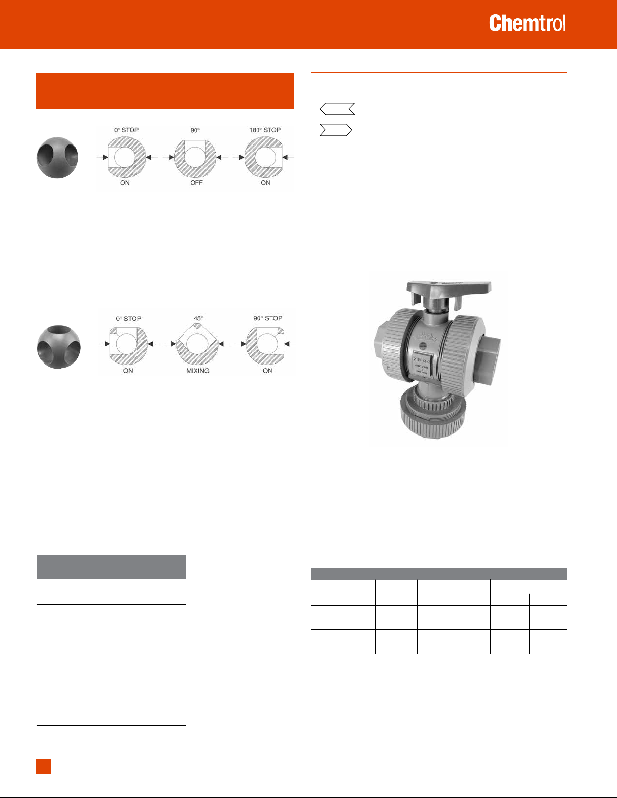
PVC and CPVC 3-Way Ball Valves, True Union
3-Position (Multiport) and 2-Position (Diverter)
The Chemtrol True Union Multiport Valve is a 3-Way/3 Position
Ball Valve
It is ideally suited for applications where flow direction and on/off controls
are needed. When the handle is rotated 180°, the three (3) positions of on,
off and on may direct flow from the branch center-inlet to one side run-outlet
(at the 0° stop position), then to shut-off (at the 90° position), and then to the
opposite side run-outlet (at the 180° stop position). The multiport may also
be used to alternately direct flow from either of the side run-inlet ports to the
branch center-outlet port, with shut-off at the mid-position (when handle is
perpendicular to the body). Cross-contamination of the two inlet streams is
prevented by all intermediate positions between the 180° stops.
www.chemtrol.com
Features
• Rated at 150 psi with non-shock water service at 73°F
•
• ADJ externally molded onto the body to indicate the seat carrier end
• Valves are manufactured and assembled without exposure to silicone
• Full port design produces minimum flow restriction with the lowest
externally molded onto the body to indicate the fixed end
FLOW
containing a PTFE seat.
of the valve. Adjustment of this union nut can compensate for wear of PTFE
seats, with no production loss to remove valve for internal adjustment.
compounds.
possible pressure drop for 90° porting.
The Chemtrol True Union Diverter Valve is a 3-Way/3 Position
Ball Valve
It is used for applications where a quarter-turn will achieve diversion of flow,
but shut-off control is not required. When the handle is rotated 90°, the two
positions of on and on may direct flow from the branch center-inlet to one
side run-outlet (at the 0° stop position). and then the opposite side run-outlet
(at the 90° stop position). The diverter may also be used to alternately divert
flow either of the side run-inlet ports to the branch center-inlet port. The
internal porting of the diverter makes no provision for shut-off. Therefore,
the valve can be used for proportional mixing at all intermediate positions
between the 90° stops.
Maximum Operating Pressure (psi)
vs. Temperature
"Operating
Temperature (F)" PVC CPVC
100 150 150
110 135 140
120 110 130
130 75 120
140 50 110
150 N.R. 100
160 N.R. 90
170 N.R. 80
180 N.R. 70
190 N.R. 60
200 N.R. 50
250 N.R. N.R.
280 N.R. N.R.
N.R. - Not recommended
Chemtrol Figure Numbers
Valve Style Trim Soc. Thd. Soc. Thd.
1/2” – 2” Multiport FKM S45M3-V T45M3-V S51M3-V T51M3-V
(3-Way/3-Position) EPDM S45M3-E T45M3-E S51M3-E T51M3-E
1/2” – 2” Diverter FKM S45D2-V T45D2-V S51D2-V T51D2-V
(3-Way/3-Position) EPDM S45D2-E T45D2-E S51D2-E T51D2-E
Elastomeric PVC CPVC
WARNING: DO NOT USE OR TEST THE PRODUCTS IN THIS CATALOG WITH COMPRESSED AIR OR OTHER GASES. Revision 1/2/2018
12
FAILURE TO FOLLOW THIS WARNING CAN RESULT IN PERSONAL INJURY OR DAMAGE TO PROPERTY.
4
®
Product Guide – Ball Valves
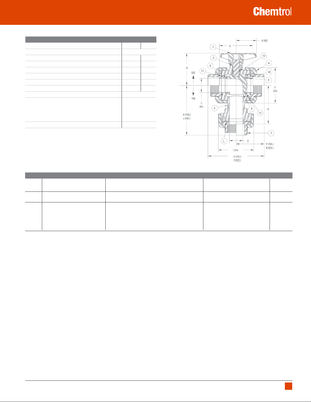
Construction Materials
1
Components
1. Handle
2. Stem PVC CPVC
3. Body PVC CPVC
4. Seat-Carrier PVC CPVC
6. Union Nut PVC CPVC
7. End Connector PVC CPVC
8. Ball PVC CPVC
9. Seat
10. O-Ring
11. O-Ring
12. O-Ring
13. O-Ring
14. O-Ring
1 All components except valve bodies are available as replacement parts.
2 Each replacement PTFE seat kit contains two seats.
3 Each replacement O-ring kit contains all the O-rings required to refurbish a particular size True
Union Ball or Check Valve (regardless of model or style), or a minimum of two pipe unions.
PVC CPVC
2
; (2 ea.) PTFE
3
– Seat-Carrier; End Seal
3
– Body; End Seal
3
– Stem; OD Seal FKM or EPDM
3
– Seat-Carrier; OD Seal
3
– Branch Union; End Seal FKM or EPDM
www.chemtrol.com
Dimensions–Weights–Flow Coefficients
Fluid Flow
Soc. & Thd Figures Socket Figures Threaded Figures Coefficient
Valve Approx.
Size A
1
B C D F G J K R Wt. Lbs. E H P Wt. Lbs C
2
Approx.2
V
3
1/2 2.07 1.94 2.00 0.50 4.19 2.41 3.56 2.69 2.13 0.64 4.00 3.50 2.06 0.60 8
3/4 2.74 2.50 2.44 0.75 5.00 2.97 4.19 3.19 2.50 1.15 4.63 4.00 2.31 1.05 19
1 2.74 2.69 2.86 1.00 5.50 3.22 4.63 3.50 2.75 1.59 5.18 4.44 2.63 1.50 36
1 1/4 2.62 3.74 4.08 1.25 6.47 3.94 5.88 4.63 3.25 3.43 6.10 5.63 3.06 3.24 55
1 1/2 2.62 3.74 4.08 1.25 6.76 3.98 6.00 4.63 3.38 3.62 6.15 5.63 3.06 3.37 55
2 3.12 4.25 5.25 2.00 8.01 4.98 7.08 5.63 3.96 7.02 7.35 6.81 3.62 6.25 149
1 Handle is not symmetrical about stem centerline. Dimension shown represents the longest
operational radius.
2 Weights shown for socket figures are CPVC models. Weights for threaded figures are PVC models.
3 Cv values were computed using equivalent cylinder length for 90° turn with full bore.
* 1 1/2" valve has conventional port on center outlet.
WARNING: DO NOT USE OR TEST THE PRODUCTS IN THIS CATALOG WITH COMPRESSED AIR OR OTHER GASES. Revision 1/2/2018
FAILURE TO FOLLOW THIS WARNING CAN RESULT IN PERSONAL INJURY OR DAMAGE TO PROPERTY.
13
®
Product Guide – Ball Valves
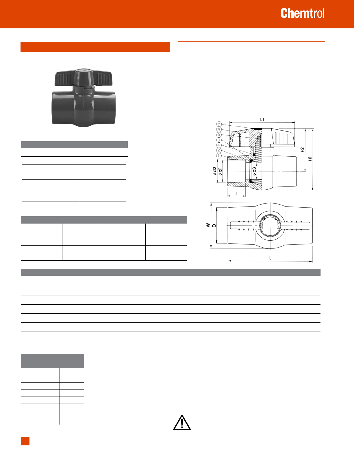
PVC Compact Economy Ball Valve
150 psi at 73°F water–non-shock
Construction Materials
Part Specification
1. Body PVC
2. Seat Seal (2) PTFE
3. Ball PVC
4. O-Ring EPDM, FKM
5. Handle ABS
6. Bolt Zinc-Plated Steel
7. Cap ABS
www.chemtrol.com
Features
• For water distribution in industrial, residential, commercial and
agricultural applications.
• Multiple industrial uses
• Durable one-piece molded body
• Excellent flow characteristics
• Socket and threaded end connections per ASTM D2467 for
Schedule 80 PVC pipe fittings
• NPT threads per ASME B1.20.1
• Rated for 150 psi water service at 73°F and 50 psi service at 140°F
• Convenient 1/4 turn operation
• Meets NSF/ANSI 14 standard
Chemtrol Figure Numbers
Material O-Rings Ends (1/2" - 2")
PVC EPDM Soc. S45CE-E
PVC EPDM Thd. T45CE-E
PVC FKM Soc. S45CE-V
PVC FKM Thd. T45CE-E
DIMENSIONS—WEIGHTS—QUANTITIES
Size
In. mm Thd./In. (NPT) d1 d2 d3 D L L1 I H1 H2 W Weight/lbs.
Fluid Flow
Coefficient
1/2 15 14 0.84 0.85 0.55 1.18 3.27 2.76 0.87 2.44 1.69 1.50 0.18 8.84
3/4 20 14 1.05 1.06 0.79 1.50 3.74 3.46 1.00 3.07 2.13 1.93 0.18 —
1 25 11.5 1.31 1.32 0.98 1.77 4.17 3.94 1.12 3.66 2.56 2.24 0.49 25.24
11/4 32 11.5 1.65 1.67 1.18 2.13 4.48 3.94 1.25 3.86 2.64 2.48 0.64 38.53
11/2 40 11.5 1.89 1.91 1.42 2.44 5.12 4.29 1.38 4.53 3.07 2.95 0.94
2 50 11.5 2.39 2.39 1.83 3.03 5.79 5.28 1.50 5.31 3.50 3.62 1.50
Maximum Operating Pressure
(psi) vs. Temperature
"Operating
Temperature (F)" PVC
100 150
110 135
120 110
130 75
140 50
150 N.R.
N.R. - Not recommended
WARNING: This product can expose you to chemicals including
styrene, which is known to the State of California to cause cancer.
For more information go to www.P65Warnings.ca.gov.
Cv
51.28
96.67
WARNING: DO NOT USE OR TEST THE PRODUCTS IN THIS CATALOG WITH COMPRESSED AIR OR OTHER GASES. Revision 1/2/2018
14
FAILURE TO FOLLOW THIS WARNING CAN RESULT IN PERSONAL INJURY OR DAMAGE TO PROPERTY.
®
Product Guide – Butterfly Valves
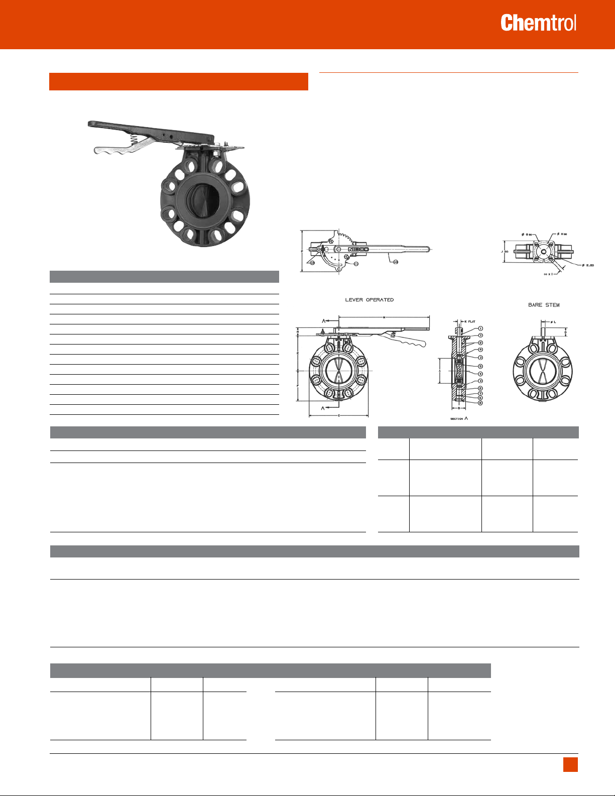
PVC and CPVC Butterfly Valves, Model C
Construction Materials
Part Material
1. Upper Stem 416 Stainless Steel
2. Bushings (3) Stainless Steel backed PTFE
3. O-Ring Stem Seal (2) EPDM or FKM
4. Body CPVC or PVC
5. Disk EPDM or FKM Encapsulated Ductile Iron
6. Lower Stem 416 Stainless Steel
7. Retaining Ring (2) 304 Stainless Steel
8. Plug LDPE (Polyethylene)
9. Face o-ring (2) EPDM or FKM
10. Handle w/Lever Malleable Iron with Epoxy Coating
11. Throttle Plate Zinc Plated Steel
12. Position Lock Zinc Plated Steel
www.chemtrol.com
Features
• Rated at 150 psi with non-shock service at 73°F
• Bolt hole pattern compatible with Class 150 ASME B16.5; BS 1560 class 150;
DN 200 ISO 2084 PN 10; and DN 200 DIN EN 1092 PN 10
• Built-in O-ring face-seals require no gaskets between mating flanges.
• A hole in the lever handle provides a blockage point for trigger lock
operation, thus, locking the valve in the off position or any of the 9
increments of opening (10° each).
• Black graphite and fluorocarbon lubricant is used to assemble Model C
butterfly valves.
• NIBCO electric and pneumatic actuation available.
• Valves with CPVC and/or FKM launching soon. Contact NIBCO Technical
Services for currently available sizes and materials.
Cv TABLE MODEL C BUTTERFLY VALVE GPM/1.0 PSI ∆P
VALVE DEGREE OPEN
SIZE NPS 10° 20° 30° 40° 50° 60° 70° 80° 90° FULL
2 0 0 3.2 13.2 26.2 44.4 67.5 80 82.7
2.5 0 0 5.5 20.4 35.5 63.4 101 161.8 183.5
3 0 0.7 13.8 36.8 58.7 95.7 154 280.2 312
4 0 0.9 24.3 68.6 128 208.5 338.5 535.3 585.6
6 0 27.7 124.2 220.9 340.1 580.7 854.7 1226.3 1357.8
8 2.8 87 209.8 372.6 648.1 1013.1 1484.1 2353.4 2860
10 6 87.6 340 679 1068.9 1719.2 2724.8 4349.9 5013
Chemtrol Figure Numbers
Seat Operating
Material Mechanism PVC CPVC
EPDM No Operator W45BG-E-0 W51BG-E-0
With Lever Handle
With Gear Operator W45BG-E-5 W51BG-E-5
FKM No Operator W45BG-V-0 W51BG-V-0
With Lever Handle
With Gear Operator W45BG-V-5 W51BG-V-5
1
10" is available with lever handle
1
W45BG-E-3 W51BG-E-3
1
W45BG-V-3 W51BG-V-3
Dimensions–Weights
Valve Handle Approx.1
Size A B C D E F G H I J K L M N P Wt./Lbs.
2 1.93 1.69 6.38 1.37 3.94 3.27 3.25 2.75 0.44 3.25 0.37 0.50 10.50 1.19 6.19
2 1/2 2.44 1.81 7.16 1.28 4.13 3.67 3.25 2.75 0.44 3.25 0.37 0.50 10.50 1.19 6.19
3 2.86 1.81 7.72 1.21 4.41 3.96 3.25 2.75 0.44 3.25 0.37 0.50 10.50 1.19 6.19
4 3.83 2.06 8.98 1.26 5.30 4.56 3.25 2.75 0.44 3.25 0.50 0.66 10.50 1.19 6.19
6 5.75 2.20 11.21 1.28 7.09 5.73 3.25 2.75 0.44 3.25 0.56 0.78 13.75 1.23 6.19
8 7.73 2.36 13.60 1.36 7.99 6.95 3.25 2.75 0.44 3.25 0.56 0.78 13.75 1.23 6.19
10 9.56 2.68 16.44 1.34 9.84 8.34 5.00 4.01 0.56 4.75 0.75 1.06 Gear Operator Only
1
Operator not included in weight. Weight is for PVC.
Maximum Operating Pressure (psi) vs. Temperature
"Operating Temperature (F)" PVC CPVC
100 150 150
110 135 140
120 110 130
130 75 120
140 50 110
N.R. - Not recommended
WARNING: DO NOT USE OR TEST THE PRODUCTS IN THIS CATALOG WITH COMPRESSED AIR OR OTHER GASES. Revision 1/2/2018
FAILURE TO FOLLOW THIS WARNING CAN RESULT IN PERSONAL INJURY OR DAMAGE TO PROPERTY.
"Operating Temperature (F)" PVC CPVC
150 N.R. 100
160 N.R. 90
170 N.R. 80
180 N.R. 70
190 N.R. N.R.
15
®
Product Guide – Butterfly Valves
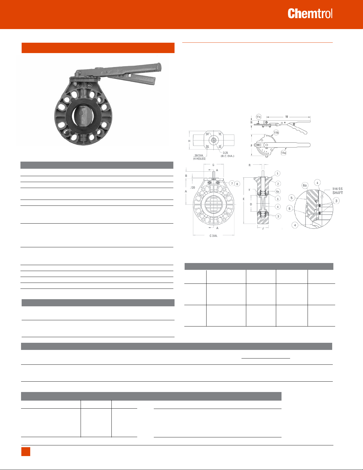
CPVC and PVC Butterfly Valves, Model B
Section A–A
Construction Materials
Part Material
2. Top Bearing Glass-Filled PTFE
3. O-Ring Seal (4 required) FKM or EPDM
4. Disk/Stem PVC
Insert-Molded
5. Body (2 required – mirror image) 3" - CPVC
6. Seat/Boot FKM or EPDM w/ GF-PTFE Upper &
Lower Bearing-Bushings
Insert-Molded
7. Cap Screws; 3" Valve (6) ea. 1/4"-20 x 7/8" Long Zinc Coated
4" Valve (6) ea. 5/16"-18 x 1" Long Zinc Coated
6" Valve (6) ea. 5/16"-18 x 1-1/2" Long & (2) ea.
5/16"-18 x 1" Long Zinc Coated
8. Hex Nuts; 3" Valve (6) ea. 1/4"-20 Zinc Coated
4" Valve (6) ea. 5/16"-18 Zinc Coated
6" Valve (8) ea. 5/16"-18 Zinc Coated
9. Lever Handle Assembly
Handle w/Lever Lock Malleable Iron
Throttling Plate Zinc Plated Steel
Position Lock Zinc Plated Steel
1 Body, disk/stem, and throttle plate for 3" size are available in CPVC only.
Cv Table
Degrees Open
Size 10° 20° 30° 40° 50° 60° 70° 80° 90°
3 4.3 16 35 62 94 135 180 235 290
4 8.6 34 76 137 215 310 420 550 690
6 17.5 67 200 265 410 580 790 1040 1340
1
w/ 316 Stainless Hex Shaft
1
; 4" & 6" - PVC
www.chemtrol.com
Features
• Rated at 150 psi with non-shock service at 73°F (6" size 115 psi)
• Mates between ASME B16.5, Class 150; ISO 2084 PN 10, DN 80; and DIN EN
1092, PN 10, DN 80. Both 4-bolt and 8-bolt patterns are in 3" size.
• PVC overmolded 316 stainless hex shaft not exposed to the liquid
• Top bearing, as well as the upper and lower bushings, are glass-filled
PTFE for ease of operation and maximum service life.
• Seat/boot design eliminates need for gaskets between mating flanges.
• Silicone-free lubricant is used to assemble Model B butterfly valves.
NIBCO
CHEMTROL
Chemtrol Figure Numbers
Seat Operating
3" (CPVC)
Material Mechanism Figure No. Figure No. Figure No.
EPDM No Operator W51BF-E-NO W45BF-E-NO W45BF-E-NO
1
With Lever
Handle W51BF-E-LH W45BF-E-LH W45BF-E-LH
With Gear Operator NA W45BF-E-GO W45BF-E-GO
1
No Operator W51BF-V-NO W45BF-V-NO W45BF-V-NO
FKM
With Lever1 Handle W51BF-V-LH W45BF-V-LH W45BF-V-LH
With Gear Operator NA W45BF-V-GO W45BF-V-GO
1 Includes throttle plate and hardware.
2 Body and disk/stem for 3" size are available in CPVC only.
2
4" (PVC) 6" (PVC)
Model-B Butterfly Valve Dimensions–Weights
Handle Approx.
Valve Size A B C D E J G H R M N P Wt./Lbs.
3 4.75 1.26 7.00 3.06 8.50 2.00 3.62 3.38 .37 10.50 1.01 6.19 3.25
4 6.13 1.22 9.00 4.00 10.63 2.22 3.62 3.38 .50 10.50 1.01 6.19 6.00
6 7.50 1.62 11.00 5.97 13.00 2.77 3.76 3.50 .56 13.75 1.01 6.19 12.00
1 Operator not included in weight.
Maximum Operating Pressure (psi) vs. Temperature
"Operating Temperature (F)" PVC CPVC
100 150 150
110 135 140
120 110 130
130 75 120
140 50 110
N.R. - Not recommended
WARNING: DO NOT USE OR TEST THE PRODUCTS IN THIS CATALOG WITH COMPRESSED AIR OR OTHER GASES. Revision 1/2/2018
16
FAILURE TO FOLLOW THIS WARNING CAN RESULT IN PERSONAL INJURY OR DAMAGE TO PROPERTY.
"Operating Temperature (F)" PVC CPVC
150 N.R. 100
160 N.R. 90
170 N.R. 80
180 N.R. 70
190 N.R. N.R.
1
®
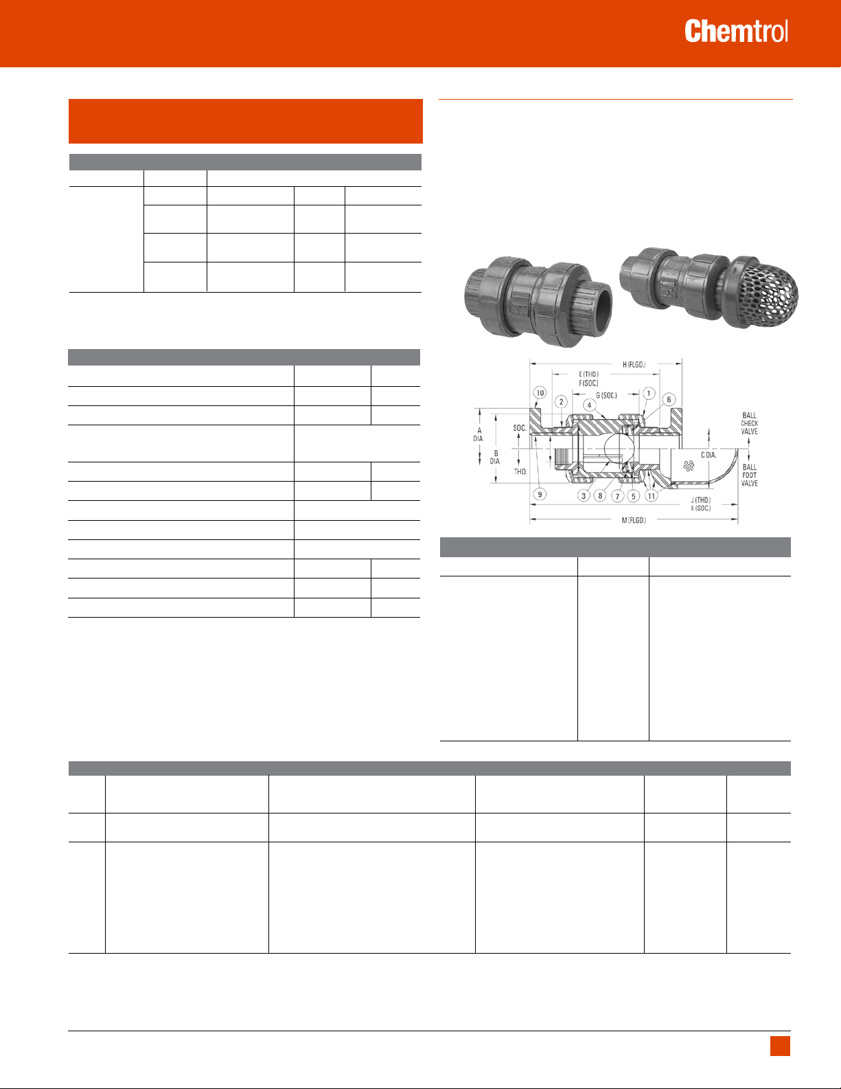
Product Guide – Ball Check Valves
PVC and CPVC True Union Ball Check, Foot, and
Vent Valves
Chemtrol Figure Numbers
Type Valve End Conn Elastomeric Trim Materials
PVC CPVC
Soc.
EPDM U45BC-E1 U51BC-E1
Ball Check Valve
EPDM U45BC-E1 U51BC-E1
Flgd. FKM F45BC-V F51BC-V
EPDM F45BC-E F51BC-E
1
1/2"–2" PVC and CPVC TU ball check figures are supplied with universal connection components
(i.e., a set of both socket and threaded end connectors). For 3" and 4" sizes of PVC and CPVC
BC valves, replace U in the figure no. with S or T for socket or threaded units respectively.
FKM U45BC-V1 U51BC-V1
Thd. FKM U45BC-V1 U51BC-V1
Features
• Rated at 150 psi with non-shock service at 73°F.
• Gravity ball check may be converted for air or gas venting by replacement
of standard ball with natural polypropylene floater ball. Then install valve
upside down for fluid to lift ball into seat.
• For foot valve, replace inlet end connection with a foot valve screen
housing assembly.
• Free oscillation of ball in guide ribs facilitates full port flow with minimum
turbulence and chatter.
• Equally effective in checking back flows from head pressure on the
discharge or suction sides of pump.
www.chemtrol.com
Construction Materials
Components
1
PVC CPVC
1. Union Nut PVC CPVC
2. End Connector PVC CPVC
3.Ball PVC CPVC
4. Body
– Standard for Check or Foot Valve
– Floater Ball for Vent Valve
1
2
Natural PP Floater Ball
PVC CPVC
5. C.V. Seat-Carrier PVC CPVC
3
6. O-ring
7. O-ring
8. O-ring
9. Plain End Pipe Nipple for Flanged Valve PVC CPVC
10. Flange–Socket for Flanged Valve PVC CPVC
11. Foot Valve Screen Housing Assembly
1 All components except valve bodies are available as replacement parts.
2 Gravity ball check valves are converted to vent valves by replacing the standard ball with a
3 Each replacement O-ring kit contains all the O-rings required to refurbish any True Union Check
4 Gravity ball check valves are converted to foot valves by replacing the union nut and end
Body & Carrier; End Seal FKM or EPDM
3
Seat-Carrier, OD Seal FKM or EPDM
3
Seat Seal FKM or EPDM
4
floater ball and inverting the valve at installation–with seat up.
or Ball Valve (regardless of model or style), or a minimum of two pipe unions.
connector on the receiving end – seat end – of the body with an F.V. screen housing assembly.
PVC CPVC
Maximum Operating Pressure (psi) vs. Temperature
"Operating Temperature (F)" PVC CPVC
100 150 150
110 135 140
120 110 130
130 75 120
140 50 110
150 N.R. 100
160 N.R. 90
170 N.R. 80
180 N.R. 70
190 N.R. 60
200 N.R. 50
250 N.R. N.R.
280 N.R. N.R.
N.R. - Not recommended
Dimensions1–Weights3–Fluid Flow Coefficients
Ball Check/Foot Ball Check Valve Ball Foot Valve Seating Head Fluid Flow
Ft – H
2
Valve E F G H Approx.
J K M Approx.3
0 Coefficient
2
Size A B C D Thd. Soc. Soc. Flgd. Wt. Lbs. Thd. Soc. Flgd. Wt. Lbs Vert. Horiz. C
1/2 3.50 1.98 2.63 0.50 3.94 4.13 2.36 6.27 0.42 6.13 6.19 7.25 0.23 6 7 5
3/4 3.88 2.44 2.63 0.75 4.65 5.02 3.00 7.38 0.72 6.88 7.13 8.25 0.29 6 7 10
1 4.26 2.83 3.63 1.00 5.08 5.40 3.12 7.99 1.05 8.13 8.25 9.63 0.37 4 5 19
1 1/4 4.62 4.08 5.50 1.25 6.38 6.75 4.22 9.65 2.46 11.13 11.25 12.75 1.34 4 5 37
1 1/2 5.00 4.08 5.50 1.50 6.38 6.99 4.21 10.18 2.62 11.13 11.50 13.13 1.34 4 5 56
2 6.00 5.23 5.50 2.00 7.36 8.02 4.99 11.45 4.76 11.75 12.13 13.75 1.88 4 5 101
3 7.50 7.17 5.50 3.00 9.98 9.98 6.17 14.22 9.21 13.38 13.38 15.63 3.00 3 4 251
4
4
9.00 7.17 5.50 3.00 20.76 20.76 16.20 16.14 14.18 18.50 18.50 16.25 3.00 3 4 251
1 Foot valve screen housing assemblies are available for the field conversion of PVC and CPVC TU ball check valves in sizes 1/2" - 4".
2 Weights shown for ball valve figures are PVC threaded models. For an approximation of CPVC check valve weights, the PVC weight may be multiplied by factor of 1.123. Weights shown for foot valves
are actually those for PVC F.V. screen housing assemblies. So, the weight for a CPVC F.V. screen housing assy. may be found by multiplying the PVC weight by the 1.123 factor. These must be added to
check valve weight for full foot valve weight.
values are based on the basic valve laying length (G).
3 C
v
4 The 4" PVC and CPVC check valves are fabricated by solvent cementing either reducing flanges or reducing couplings onto the ends of a 3" valve with plain-end nipples.
WARNING: DO NOT USE OR TEST THE PRODUCTS IN THIS CATALOG WITH COMPRESSED AIR OR OTHER GASES. Revision 1/2/2018
FAILURE TO FOLLOW THIS WARNING CAN RESULT IN PERSONAL INJURY OR DAMAGE TO PROPERTY.
3
V
17
®
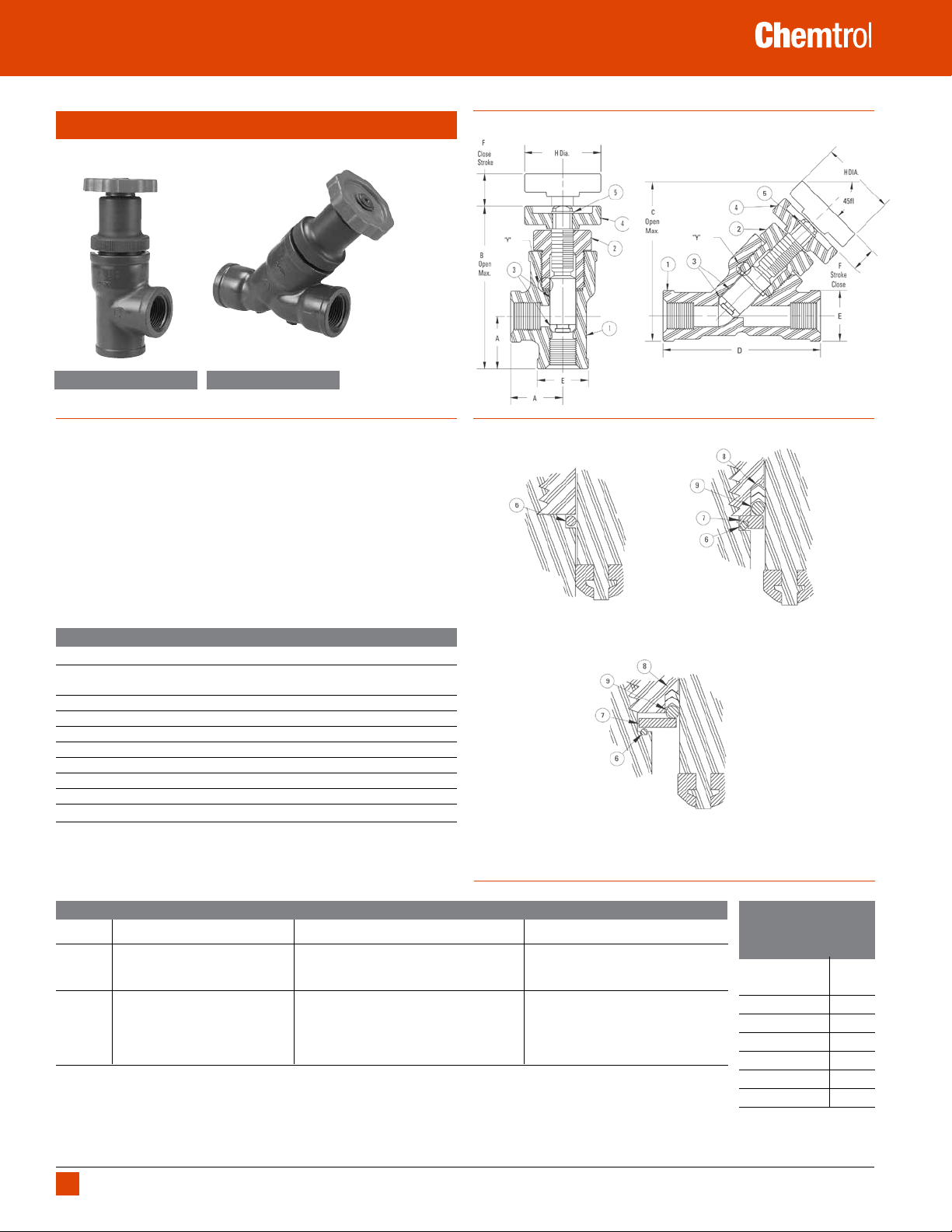
Product Guide – Angle & Globe Valves
PVC Angle and Y-Pattern Globe Valves
Both styles
Chemtrol Figure No.
T45AC-V
Chemtrol Figure No.
T45YP-V
Features
• Rated at 150 psi with non-shock service at 73°F
• Y-pattern style has a minimal pressure-drop when compared with a
conventional upright style globe valve
• Malleable glass reinforced PTFE seat disk ensures long-lasting positive
sealing.
• Stub acme thread on stem provides rapid open-close operation.
• Liquid or slurry never touches stem threads.
• Can be used for both on-off and throttling control of fluid flow.
• Easy in-line maintenance.
available with
threaded end
connections only.
www.chemtrol.com
Construction Materials
Detail “Y” Enlarged View
1/4” Size Valve
Detail “Y” Enlarged View
1/2” & 3/4” Size Valve
Part Material
1. Body – Angle PVC
– or Y-Pattern PVC
2. Bonnet PVC
3. Stem Assembly PVC w/ Glass Filled PTFE Seat Disk
4. Handle PVC
5. Snap Ring Retainer Zinc Plated Steel
6. O-Ring – Body Seal FKM
7. Energizer Back-Up Washer
8. CV Stem Seal (2 required)
9. O-Ring – Stem Seal Energizer
1 Items not required for 1/4" valve.
1
PVC
1
PTFE
1
FKM
Detail “Y” Enlarged View
1” Size Valve
Valve Dimensions – Weights – Flow Coefficients
Common Dimensions Angle Valve
1
Y-Pattern Valve
1
Hub Close Handle Center- Open Flow Approx. End- Open Flow Approx.
Valve Dia. Stroke Dia. To-Face Max. Coef. Weight To-End Max. Coef. Weight
Size E F H A B C
2
Lbs. D C C
v
2
Lbs.
v
1/4 0.88 .44 1.32 0.88 3.56 1.1 0.11 2.75 2.75 3.1 0.12
1/2 1.25 .75 2.19 1.31 5.38 5.4 0.28 3.50 4.63 17.7 0.30
3/4 1.50 .94 2.19 1.41 6.50 9.9 0.47 4.25 5.56 32.5 0.53
1 1.75 1.19 2.19 1.88 7.88 15.8 0.69 5.00 6.31 49.3 0.73
1 Available with threaded end connections only.
measured with valves completely open.
2 C
V
Maximum Operating
Pressure (psi) vs.
Temperature
"Operating
Temperature (F)" PVC
100 150
110 135
120 110
130 75
140 50
150 N.R.
N.R. - Not recommended
WARNING: DO NOT USE OR TEST THE PRODUCTS IN THIS CATALOG WITH COMPRESSED AIR OR OTHER GASES. Revision 1/2/2018
18
FAILURE TO FOLLOW THIS WARNING CAN RESULT IN PERSONAL INJURY OR DAMAGE TO PROPERTY.

®
Product Guide – Lab Valves
PVC ChemcockTM and Calibrated Needle Lab Valves
Chemtrol Figure No.
A45CC-V 1/4" Hose x 1/4" MPT
M45CC-V 1/4" MPT x 1/4" MPT
Features
• Rated at 150 psi with non-shock service at 73°F
• Its (4.8) calculated fluid flow coefficient (Cv) is based on the laying length
being equivalent to 1/4" Schedule 80 pipe.
• Easily adaptable to any type of connection.
• Opens and closes with only a quarter turn.
• Replaceable FKM O-ring seats and seals.
• Corrosion-resistant all thermoplastic PVC construction.
• No sticking or galling.
• Full port design.
www.chemtrol.com
Approx. Weight 0.06 lbs.
Construction Materials
Part Material
1. Handle PVC
2. Ball/Stem PVC
3. Body End – Hose PVC
or Thread PVC
4. Body Half – Stem Side PVC
5. O-Ring – Body Seal FKM
6. O-Ring – Ball Seats (2) FKM
7. O-Ring – Stem Seal FKM
8. Handle Screw Cadmium Plated Steel
Chemtrol Figure No.
T45CN-V 1/4" FPT x 1/4" FPT
Features
• Rated at 150 psi with non-shock service at 73°F
• Precise flow measurement.
Approx. Weight 0.13 lbs.
• Positive stop for safe operation.
• PTFE seat prevents wear on needle.
• Accurately adjust the flow by observing the knob handle exposing
numerals molded on the valve body
Knob Position GPM @ Constant 50 PSI
8 .85
7 1.41
6 1.79
5 2.15
4 2.42
3 3.15
2 4.40
Construction Materials
Part Material
1. Adjustment Knob PVC
2. Stem Assembly PVC w/PTFE Seat Seal
& FKM Stem Seal
3. Body PVC
4. Retainer Washer PVC
5. Snap Ring Stainless Steel
6. Screw Stainless Steel
Maximum Operating
Pressure (psi) vs.
Temperature
"Operating
Temperature (F)" PVC
100 150
110 135
120 110
130 75
140 50
150 N.R.
N.R. - Not recommended
1 4.50
WARNING: DO NOT USE OR TEST THE PRODUCTS IN THIS CATALOG WITH COMPRESSED AIR OR OTHER GASES. Revision 1/2/2018
FAILURE TO FOLLOW THIS WARNING CAN RESULT IN PERSONAL INJURY OR DAMAGE TO PROPERTY.
19

®
Product Guide – Valve Accessories
www.chemtrol.com
Alternative Manual Operators
Part Numbers For Alternative Manual Operators
Accessory Use Valve Size
1/2 3/4 & 1 1 1/4 &1 1/2 2 2 1/2 3 4 6 8
2" Sq. Nut
Stem Adapter PVC for TB Ball Valves 21630007 21630009 21630011 21630012 — 21630014 21630016 21630016 —
PVC for HV Ball Valves 21630007 21630009 21630011 21630011 — — — — —
Round Safety PVC for TB Ball Valves 81616007 81616009 81621011 81621012 — — — — —
Handle PVC for HV Ball Valves 81616007 81616009 81621011 81621011 — — — — —
2" Square Nut Stem Adapter–Permits operation of a valve with a standard
utility (AWWA) wrench. The most common application is for valves located in
an underground valve box. The square nut for ball valves is made from PVC. It
snaps onto the stem and locks into the slot for turning-stops of a ball valve of any
material, in place of its standard handle.
Round Safety Handle–Design prevents accidental operation of low-torque
ball valve by snagging the lever handle with personal clothing or equipment.
Suitable for PVC and CPVC Tru-Bloc
®
True Union Ball Valves, Model D.
Standoff Stem Extensions for Ball Valves–Provide handle clearance, with the
integrity of turning-stops, for insulating, panel-mounting, or shallow submerged
applications. These extensions are made of solid PVC, and are short; so top support is
not required. Although priced in increments of 1" standoff, between handle and stem,
they can be supplied in exact lengths if specified when ordered. And, if the extension is
to be installed on a valve of material other than PVC or CPVC, that must also be specified
when ordering.
PVC Standoff Stem Extensions For Ball Valve
Valve Size
Length
Of Ext. 1/2 3/4 & 1 1 1/4 2 3 4 & 6
& 1 1/2
1" Long 21618007 21618009 — — — —
2" Long 21617150 21617175 21617214 21617226 21617069 21617076
3" Long 21617151 21617177 21617216 21617229 21617249 21617078
4" Long 21617153 21617179 21617218 21617231 21617251 21617257
6" Long 21617157 21617183 21617222 21617235 21617252 21617260
WARNING: DO NOT USE OR TEST THE PRODUCTS IN THIS CATALOG WITH COMPRESSED AIR OR OTHER GASES. Revision 1/2/2018
20
FAILURE TO FOLLOW THIS WARNING CAN RESULT IN PERSONAL INJURY OR DAMAGE TO PROPERTY.

®
Product Guide – Valve Accessories
www.chemtrol.com
Valve Lockout Devices
Part Numbers for Valve Lockout Devices
Type Lockout
Device Mounted 1/2 3/4 1 1 1/4 1 1/2 2 2 1/2 3 4 6 8
BV Handle and Locking Ring Kit Field 81644007 81644008 81644009 81644011 81644011 81644012
PP Lockout Cover for Ball Valve Field 70060210 70060210 70060210 70060211 70060211 70060211 — 70060212 — — —
Ball Valve-Mounted Lockout Kit Field 70050007 70050008 70050009 70050011 70050011 70050012 — 70050014 70050016 70050016 —
W/ Std. Plastic Handle Factory 70050107 70050108 70050109 70050111 70050111 70050112 — 70050114 70050116 70050116 —
Ball Valve-Mounted Lockout Kit Field 70080007 70080008 70080009 70080011 70080011 — — — — — —
W/ Lever Handle and Index Plate Factory 70080107 70080108 70080109 70080111 70080111 — — — — — —
Meet OSHA Standard 29 CFR 1910.147; The Control of Hazardous Energy (Lockout/
Tagout). The range in complexity and cost of these devices generally reflects the
various usage requirements of frequency, permanency, and multiples of function. The
gang hasp, for multi-discipline locking, is shown for the purpose of illustration only. It
is not available with any of the devices.
TB Ball Valve Handle and Locking Ring Kit
The locking ring surrounds the valve body for permanent attachment to the valve.
When the lock device is removed from the handle and retaining arm of the ring,
the ring arm simply hangs beneath the valve. This single function kit is effective for
valve-off lockout only or may be added to other Tru-Bloc
Location
Valve Size
®
valves of any material.
— — — — —
Ball Valve Lockout Cover
This two-piece molded polypropylene split clamshell closure, which is hinged to
fasten around the common handles of Tru-Bloc valves, is a simple provision for
maintenance or operations lockout. The cover can be locked with the handle in the
on, off, or any throttling position, but when the cover is locked the handle position,
relating ball posture, is not visible. One of three cover sizes is usually transported
to the point of use, because a cover is not easily attached to the valve when it is
unlocked.
TB Ball Valve-Mounted Lockout Kit w/Standard Plastic Handle
This all-plastic kit, permanently mounted on a valve, may be locked in the on or off
valve position. Whether locked or unlocked, the distinguishing handle position is
clearly visible at all times, including throttling postures.
TB Ball Valve-Mounted Lockout Kit w/ Lever Handle and Index Plate
This kit consists of a lever-lock handle and index plate, adapted to fit a ball valve
mount. It provides for locking the valve in the off position or any of the 9 increments
of opening (10° each), including the full on position. The handle position, aligned
with the fully on ball posture, is visible at all times.
WARNING: DO NOT USE OR TEST THE PRODUCTS IN THIS CATALOG WITH COMPRESSED AIR OR OTHER GASES. Revision 1/2/2018
FAILURE TO FOLLOW THIS WARNING CAN RESULT IN PERSONAL INJURY OR DAMAGE TO PROPERTY.
21

®
Product Guide – Fittings
PVC Schedule 80
www.chemtrol.com
Couplings 24
Adapters 25
Elbows 26
Tees 27
Plugs 28
Caps 28
Bushings 29
Class 150 Flanges 30
Unions 32
Metal Transition Unions 33
Corzan® CPVC Schedule 80
Couplings 34
Adapters 35
Elbows 35
Tees 36
Plugs 37
Caps 38
Bushings 38
Class 150 Flanges 40
Unions 42
Corzan® is a registered trademark of The Lubrizol Corporation.
WARNING: DO NOT USE OR TEST THE PRODUCTS IN THIS CATALOG WITH COMPRESSED AIR OR OTHER GASES. Revision 1/2/2018
22
FAILURE TO FOLLOW THIS WARNING CAN RESULT IN PERSONAL INJURY OR DAMAGE TO PROPERTY.

®
Product Guide – PVC Schedule 80
Fitting Terms and Abbreviations Schedule 80 only
FPT Female Pipe Thread
CL Close
MPT Male Pipe Thread
S Female Socket
SH Short
SPG Male End (Spigot)
Dimensions and Standards
Universal Part No. Chemtrol Part No.
(Discontinued)
XX XX - XXX XX XXX XXX
1 2 4 1 2 4
Material and Product Type
1 1 1
Product Universal Chemtrol Chemtrol
Line Part Number Part Number Figure Number
PVC Sch. 80 8 01 45
CPVC Sch. 80 18 05 51
PP Black Sch. 80. 28 07 61
Chempure PP Sch. 80 78 10 62
PVDF Red Sch. 80 38 58 65
NPVDF Natural Sch. 80 48 06 66
Fitting Description
2 2 2 3
Fitting & End Universal Chemtrol Chemtrol Figure No.
Connection Part No. Part No. Fitting Connection(s)
Tee-Socket 01 013 00 Blank
Tee-Socket x Thread 02 015 12 Blank
Tee-Thread 05 014 12 3-3
90° ELL-Socket 06 001 07 Blank
90° ELL-Socket x Thread 07 003 07 3
90° ELL-Thread 08 002 07 3-3
90° Street ELL-Male 10 219 07 4
Thread x Socket
90° Street ELL-Male 12 213 07 3-4
Thread x Thread
45° ELL-Socket 17 007 06 Blank
45° ELL-Thread 19 008 06 3-3
Coupling-Socket 29 025 01 Blank
Coupling-Thread 30 026 01 3-3
Adapter Coupling-Socket 35 027 03 Blank
x Thread
Male Adapter-Male 36 217 04 Blank
Thread x Socket
Reducing Bushing-Socket 37 049 18 Blank
Reducing Bushing- 38 051 18 3
Spigot x Thread
Reducing Bushing-Thread 39 050 18 3-4
Cap-Socket 47 031 17 Blank
Cap-Thread 48 032 17 3
Plug-Spigot 49 042 16 Blank
Plug-Thread 50 043 16 4
Flange-Socket 51 045 51 Blank
Flange-Thread 52 044 51 3
Flange-Blind 53 046 19 Blank
Van Stone Flange-Socket 54 069 51 A
Union-Socket 97 028 33 Blank
Union-Thread 98 029 33 3-3
Nipple-Thread x Thread 61 053 29 Blank
www.chemtrol.com
Chemtrol Figure
XX XX - X - X - SIZE
1 2 3 4
Size Description
4 4 4
Universal Chemtrol Chemtrol
Size Part Number Part Number Figure Number
1/4 002 004
1/2 005 007
3/4 007 008
1 010 009
1 1/4 012 010
1 1/2 015 011
2 020 012
2 1/2 025 013
3 030 014
4 040 016
6 060 018
8 080 019
10 100 020
12 120 021
1/2 x 1/4 072 027
3/4 x 1/4 098 029
3/4 x 1/2 101 031
1 x 1/4 128 032
1 x 1/2 130 034
1 x 3/4 131 035
1 1/4 x 1/2 166 038
1 1/4 x 3/4 167 039
1 1/4 x 1 168 040 Simply State Size
1 1/2 x 1/2 209 043
1 1/2 x 3/4 210 044
1 1/2 x 1 211 045
1 1/2 x 1 1/4 212 046
2 x 1/2 247 049
2 x 3/4 248 050
2 x 1 249 051
2 x 1 1/4 250 052
2 x 1 1/2 251 053
2 1/2 x 1/2 287 056
2 1/2 x 3/4 288 057
2 1/2 x 1 289 058
2 1/2 x 1 1/4 290 059
2 1/2 x 1 1/2 291 060
2 1/2 x 2 292 061
3 x 1 335 066
3 x 1 1/4 336 067
3 x 1 1/2 337 068
3 x 2 338 069
3 x 2 1/2 339 069
4 x 2 420 076
4 x 2 1/2 421 077
4 x 3 422 078
6 x 2 528 082
6 x 3 530 084
6 x 4 532 085
8 x 6 585 088
WARNING: DO NOT USE OR TEST THE PRODUCTS IN THIS CATALOG WITH COMPRESSED AIR OR OTHER GASES. Revision 1/2/2018
FAILURE TO FOLLOW THIS WARNING CAN RESULT IN PERSONAL INJURY OR DAMAGE TO PROPERTY.
23

®
Product Guide – PVC Schedule 80
Couplings
Chemtrol
Fig. No.
4501 Socket Coupling (S x S)
Nominal Universal Approx. Dim.
Size Part No. Lbs./Ea. N
1/4 829-002 0.05 0.12
1/2 829-005 0.09 0.25
3/4 829-007 0.13 0.25
1 829-010 0.14 0.25
1 1/4 829-012 0.22 0.25
1 1/2 829-015 0.29 0.25
2 829-020 0.42 0.25
2 1/2 829-025 0.68 0.20
3 829-030 1.05 0.19
4 829-040 1.83 0.19
6 829-060 3.56 0.25
8 829-080 8.69 0.25
10 829-100 13.88 0.38
12 829-120 22.69 0.50
4501-R Reducing Socket Coupling (S x S)
Nominal Universal Approx. Dim.
Size Part No. Lbs./Ea. N
3/4 x 1/2 829-101 0.12 0.44
1 x 1/2 829-130 0.18 0.67
1 x 3/4 829-131 0.19 0.55
1 1/4 x 3/4 829-167 0.26 0.72
1 1/4 x 1 829-168 0.27 0.60
1 1/2 x 1/2 829-209 0.31 0.81
1 1/2 x 3/4 829-210 0.31 0.76
1 1/2 x 1 829-211 0.33 0.63
1 1/2 x 1 1/4 829-212 0.35 0.51
2 x 1 829-249 0.44 0.75
2 x 1 1/2 829-251 0.50 0.50
3 x 2 829-338 1.00 1.24
4 x 2 829-420 1.59 1.59
4 x 3 829-422 1.88 1.20
Other Reducing Couplings are produced by solvent cementing appropriate Reducer Bushings into
Socket Couplings. They may be ordered as factory fabrications or may be assembled in the field.
www.chemtrol.com
Chemtrol
Fig. No.
4501-3-3 Thread Coupling (FPT x FPT)
Nominal Universal Approx. Dim.
Size Part No. Lbs./Ea. L
1/4 830-002 0.06 1.41
1/2 830-005 0.09 2.03
3/4 830-007 0.14 2.28
1 830-010 0.23 2.53
1 1/4 830-012 0.33 2.78
1 1/2 830-015 0.41 3.03
2 830-020 0.60 3.28
2 1/2 830-025 0.86 3.76
3 830-030 1.22 4.00
4 830-040 2.13 4.75
4501-3-3-R Reducing Thread Coupling (FPT x FPT)
Nominal Universal Approx. Dim.
Size Part No. Lbs./Ea. L
3/4 x 1/2 830-101 0.14 2.34
1 x 1/2 830-130 0.20 2.70
1 x 3/4 830-131 0.18 2.70
1 1/4 x 3/4 830-167 0.29 3.00
1 1/4 x 1 830-168 0.31 3.00
1 1/2 x 3/4 830-210 0.35 3.16
1 1/2 x 1 830-211 0.38 3.16
1 1/2 x 1 1/4 830-212 0.40 3.16
2 x 1 830-249 0.50 3.40
2 x 1 1/2 830-251 0.56 3.40
3 x 2 830-338 1.15 4.66
4 x 2 830-420 1.79 5.38
4 x 3 830-422 2.11 5.38
Other Reducing Couplings are produced by solvent cementing appropriate Reducer Bushings
into Socket Couplings. They may be ordered as factory fabrications or may be assembled in
the field.
WARNING: DO NOT USE OR TEST THE PRODUCTS IN THIS CATALOG WITH COMPRESSED AIR OR OTHER GASES. Revision 1/2/2018
24
FAILURE TO FOLLOW THIS WARNING CAN RESULT IN PERSONAL INJURY OR DAMAGE TO PROPERTY.

®
Product Guide – PVC Schedule 80
Adapters
Chemtrol
Fig. No.
4503 Female Adapter Coupling (S x FPT)
Nominal Universal Approx. Dim.
Size Part No. Lbs./Ea. O
1/4 835-002 0.04 0.77
1/2 835-005 0.09 1.14
3/4 835-007 0.14 1.27
1 835-010 0.21 1.39
1 1/4 835-012 0.30 1.52
1 1/2 835-015 0.38 1.64
2 835-020 0.56 1.77
2 1/2 835-025 0.77 1.98
3 835-030 1.15 2.10
4 835-040 1.95 2.47
www.chemtrol.com
Chemtrol
Fig. No.
4550 Tank Adapter (Tank x FPT)
Nominal Universal Approx. Dim. Dim. Dim
Size Part No. Lbs./Ea. A B C
1/2 0.20 2.00 2.75 1.38
3/4 Use 0.35 2.38 2.88 1.63
1 Figure 0.40 2.56 2.88 1.88
1 1/4 No. & 0.55 3.25 3.00 2.63
1 1/2 Nom. 0.65 3.25 3.00 2.63
2 Size 1.15 4.38 3.25 3.25
3
Note: Gasket is EPDM and nut is self-tightening left hand thread.
2.10 6.00 3.63 4.50
4504 Male Adapter (S x MPT)
Nominal Universal Approx. Dim.
Size Part No. Lbs./Ea. O
1/2 836-005 0.04 0.94
3/4 836-007 0.06 0.97
1 836-010 0.10 1.15
1 1/4 836-012 0.14 1.12
1 1/2 836-015 0.19 1.12
2 836-020 0.27 1.20
2 1/2 836-025 0.50 1.89
3 836-030 0.79 1.99
4 836-040 1.30 2.09
M
For complete technical information and more, refer
to our website at www.chemtrol.com.
WARNING: DO NOT USE OR TEST THE PRODUCTS IN THIS CATALOG WITH COMPRESSED AIR OR OTHER GASES. Revision 1/2/2018
FAILURE TO FOLLOW THIS WARNING CAN RESULT IN PERSONAL INJURY OR DAMAGE TO PROPERTY.
25

®
Product Guide – PVC Schedule 80
Elbows
Chemtrol
Fig. No.
4507 Socket 90° Elbow (S x S)
Nominal Universal Approx. Dim.
Size Part No. Lbs./Ea. G
1/4 806-002 0.01 0.33
1/2 806-005 0.11 0.52
3/4 806-007 0.16 0.69
1 806-010 0.21 0.75
1 1/4 806-012 0.25 0.92
1 1/2 806-015 0.38 1.06
2 806-020 0.57 1.27
2 1/2 806-025 1.16 1.53
3 806-030 1.50 1.84
4 806-040 3.08 2.34
6 806-060 8.03 3.50
8 806-080 15.25 4.56
10 806-100 27.70 5.75
12 806-120 43.90 6.89
11
www.chemtrol.com
Chemtrol
Fig. No.
4507-3-3 Thread 90° Elbow (FPT x FPT)
Nominal Universal Approx. Dim.
Size Part No. Lbs./Ea. H
1/4 808-002 0.04 0.97
1/2 808-005 0.12 1.41
3/4 808-007 0.18 1.71
1 808-010 0.28 1.89
1 1/4 808-012 0.42 2.18
1 1/2 808-015 0.55 2.45
2 808-020 0.82 2.78
2 1/2 808-025 1.25 3.31
3 808-030 1.90 3.74
4 808-040 3.62 4.62
4506 Socket 45° Elbow (S x S)
4507-3 Socket x Thread 90° Elbow (S x FPT)
Nominal Universal Approx. Dim. Dim.
Size Part No. Lbs./Ea. G
1/2 807-005 0.12 0.52 1.41
3/4 807-007 0.17 0.69 1.71
1 807-010 0.28 0.75 1.89
1 1/4 807-012 0.33 0.92 2.18
1 1/2 807-015 0.55 1.06 2.45
2 807-020 0.82 1.27 2.78
H
4507-12/4506-12 Flanged ELLs
Flanged fitting center-to-face dimensions may be found on page 32. When
ordering, specify the figure number and the nominal size (e.g., 2" Schedule 80
PVC flanged 90° Elbow–4507-12 2")
Nominal Universal Approx. Dim.
Size Part No. Lbs./Ea. J
1/4 817-002 0.03 0.18
1/2 817-005 0.04 0.26
3/4 817-007 0.14 0.33
1 817-010 0.15 0.37
1 1/4 817-012 0.24 0.43
1 1/2 817-015 0.31 0.47
2 817-020 0.48 0.61
2 1/2 817-025 0.93 0.68
3 817-030 1.23 0.78
4 817-040 2.46 1.02
6 817-060 6.21 1.75
8 817-080 13.03 2.22
10 817-100 19.70 2.61
12 817-120 32.70 3.08
WARNING: DO NOT USE OR TEST THE PRODUCTS IN THIS CATALOG WITH COMPRESSED AIR OR OTHER GASES. Revision 1/2/2018
26
FAILURE TO FOLLOW THIS WARNING CAN RESULT IN PERSONAL INJURY OR DAMAGE TO PROPERTY.

®
Product Guide – PVC Schedule 80
Chemtrol
Fig. No.
4506-3-3 Thread 45° Elbow (FPT x FPT)
Nominal Universal Approx. Dim.
Size Part No. Lbs./Ea. K
1/4 819-002 0.04 0.82
1/2 819-005 0.11 1.15
3/4 819-007 0.13 1.35
1 819-010 0.25 1.51
1 1/4 819-012 0.35 1.70
1 1/2 819-015 0.48 1.86
2 819-020 0.71 2.13
2 1/2 819-025 1.03 2.46
3 819-030 1.53 2.69
4 819-040 2.52 3.30
Tees
4511 Socket Tee (S x S x S)
www.chemtrol.com
Chemtrol
Fig. No.
4511-12 Flanged Tee
Flanged fitting center-to-face dimensions may be found on page 32. When
ordering, specify the figure number and the nominal size (e.g., 2" Schedule 80
PVC flanged tee–4511-12 2")
4511-R Reducing Socket Tee (S x S x S)
Nominal Universal Approx. Dim. Dim. Dim.
Size Part No. Lbs./Ea. G G I
3/4 x 3/4 x 1/2 801-101 0.18 0.52 0.52 0.62
1 x 1 x 1/2 801-130 0.24 0.53 0.53 0.73
1 x 1 x 3/4 801-131 0.26 0.63 0.63 0.74
1 1/2 x 1 1/2 x 3/4 801-210 0.48 0.67 0.67 1.05
1 1/2 x 1 1/2 x 1 801-211 0.52 0.77 0.77 1.04
2 x 2 x 1/2 801-247 0.61 0.61 0.61 1.30
2 x 2 x 3/4 801-248 0.65 0.71 0.71 1.30
2 x 2 x 1 801-249 0.69 0.81 0.81 1.30
2 x 2 x 1 1/2 801-251 0.83 1.08 1.08 1.30
3 x 3 x 2 801-338 1.73 1.37 1.37 1.86
4 x 4 x 2 801-420 2.79 1.42 1.42 2.36
4 x 4 x 3 801-422 3.33 1.90 1.90 2.38
6 x 6 x 4 801-532 7.29 2.60 2.60 3.56
Nominal Universal Approx. Dim. Dim. Dim.
Size Part No. Lbs./Ea. G G I
1/4 801-002 0.05 0.33 0.33 0.33
1/2 801-005 0.11 0.52 0.52 0.52
3/4 801-007 0.17 0.69 0.69 0.69
1 801-810 0.25 0.75 0.75 0.75
1 1/4 801-012 0.48 0.92 0.92 0.92
1 1/2 801-015 0.52 1.06 1.06 1.06
2 801-020 0.97 1.27 1.27 1.27
2 1/2 801-025 1.50 1.53 1.53 1.53
3 801-030 2.00 1.84 1.84 1.84
4 801-040 3.54 2.34 2.34 2.34
6 801-060 10.47 3.50 3.50 3.50
8 801-080 20.57 4.56 4.56 4.56
10 801-100 35.40 5.75 5.75 5.75
12 801-120 58.40 6.89 6.89 6.89
4511
4512 Socket x Thread Tee (S x S x FPT)
Nominal Universal Approx. Dim. Dim. Dim.
Size Part No. Lbs./Ea. G G H
1/2 802-005 0.16 0.52 0.52 1.41
3/4 802-007 0.24 0.69 0.69 1.71
1 802-010 0.34 0.75 0.75 1.89
1 1/4 802-012 0.57 0.92 0.92 2.18
1 1/2 802-015 0.80 1.06 1.06 2.45
2 802-020 1.13 1.27 1.27 2.78
For questions concerning thermoplastic piping
systems, please call or fax: 888.446.4226 (ph),
888.336.4226 (fx).
11
WARNING: DO NOT USE OR TEST THE PRODUCTS IN THIS CATALOG WITH COMPRESSED AIR OR OTHER GASES. Revision 1/2/2018
FAILURE TO FOLLOW THIS WARNING CAN RESULT IN PERSONAL INJURY OR DAMAGE TO PROPERTY.
27

®
Product Guide – PVC Schedule 80
Chemtrol
Fig. No.
4512-3-3 Threaded Tee (FPT x FPT x FPT)
Nominal Universal Approx. Dim.
Size Part No. Lbs./Ea. H
1/4 805-002 0.05 0.97
1/2 805-005 0.16 1.41
3/4 805-007 0.26 1.71
1 805-010 0.35 1.89
1 1/4 805-012 0.57 2.18
1 1/2 805-015 0.75 2.45
2 805-020 1.13 2.78
2 1/2 805-025 1.79 3.31
3 805-030 2.60 3.74
4 805-040 4.63 4.62
Plugs
4516-4 Thread Plug (MPT)
www.chemtrol.com
Caps
Chemtrol
Fig. No.
4517 Socket Cap* (S)
Nominal Universal Approx. Dim.
Size Part No. Lbs./Ea. O
1/4 847-002 0.03 0.25
1/2 847-005 0.06 0.39
3/4 847-007 0.08 0.37
1 847-010 0.14 0.41
1 1/4 847-012 0.20 0.40
1 1/2 847-015 0.26 0.41
2 847-020 0.38 0.42
2 1/2 847-025 0.57 0.57
3 847-030 0.87 1.29
4 847-040 1.53 1.58
6 847-060 3.77 2.13
*Sizes 2" and smaller are flat; 2 1/2" and larger are domed.
4517-3 Thread Cap* (FPT)
C
Nominal Universal Approx. Dim.
Size Part No. Lbs./Ea. L
L
1/4 850-002 0.01 0.85
1/2 850-005 0.03 1.04
3/4 850-007 0.03 1.10
1 850-010 0.06 1.25
1 1/4 850-012 0.10 1.66
1 1/2 850-015 0.14 1.78
2 850-020 0.19 1.92
2 1/2 850-025 0.29 2.18
3 850-030 0.51 2.42
4 850-040 0.95 2.81
1/4" Plug is solid, only
WARNING: DO NOT USE OR TEST THE PRODUCTS IN THIS CATALOG WITH COMPRESSED AIR OR OTHER GASES. Revision 1/2/2018
28
FAILURE TO FOLLOW THIS WARNING CAN RESULT IN PERSONAL INJURY OR DAMAGE TO PROPERTY.
Nominal Universal Approx. Dim.
Size Part No. Lbs./Ea. W
1/4 848-002 0.01 0.89
1/2 848-005 0.06 1.28
3/4 848-007 0.10 1.38
1 848-010 0.15 1.55
1 1/4 848-012 0.22 1.66
1 1/2 848-015 0.29 1.80
2 848-020 0.41 1.93
2 1/2 848-025 0.64 2.35
3 848-030 0.93 3.19
4 848-040 1.73 3.86
*Sizes 2" and smaller are flat; 2 1/2" and larger are domed.

®
Product Guide – PVC Schedule 80
Bushings
Design Styles
The design style of most bushings is to have a solid wall between the
inside and outside connections. Some of the multistep reductions with
exceedingly thick cross-sections are not solid. This design style achieves
structural support with a web of ribs attaching the inner and outer
connection walls, with the open area toward the exterior bushing face. The
styles are denoted by W and S for webbed and solid designs respectively.
Webbed design Solid design
Chemtrol
Fig. No.
4518 Flush Socket Reducer Bushing (SPG x S)
www.chemtrol.com
Chemtrol
Fig. No.
4518 Flush Socket Reducer Bushing (SPG x S) (cont.)
Nominal Universal Approx. Design Dim. Dim.
Size Part No. Lbs./Ea. Style L
4 x 2 837-420 1.14 W 2.81 1.30
4 x 2 1/2 837-421 1.14 S 2.81 1.03
4 x 3 837-422 0.93 S 2.81 0.91
6 x 2 837-528 3.28 W 3.06 1.55
6 x 4 837-532 2.68 S 3.06 0.78
8 x 6 837-585 5.46
10 x 6 837-626 10.68 W 5.59 2.56
10 x 8 837-628 9.36 S 5.59 1.09
12 x 8 837-668 16.73 W 6.59 2.09
12 x 10 837-670 12.77 S
Other Reducing Couplings are produced by solvent cementing appropriate Reducer Bushings into
Socket Couplings. They may be ordered as factory fabrications or may be assembled in the field.
S
4518-3 Flush Spigot x Thread Reducer Bushing (SPG x FPT)
L NN
4.59 1.56
6.59 1.09
Nominal Universal Approx. Design Dim. Dim.
Size Part No. Lbs./Ea. Style L
1/2 x 1/4 837-072 0.03 S 1.17 0.53
3/4 x 1/2 837-101 0.05 S 1.15 0.26
1 x 1/2 837-130 0.06 S 1.28 0.39
1 x 3/4 837-131 0.05 S 1.28 0.27
1 1/4 x 1/2 837-166 0.10 S 1.41 0.52
1 1/4 x 3/4 837-167 0.10 S 1.41 0.40
1 1/4 x 1 837-168 0.06 S 1.41 0.27
1 1/2 x 1/2 837-209 0.12 W 1.53 0.64
1 1/2 x 3/4 837-210 0.10 S 1.53 0.52
1 1/2 x 1 837-211 0.08 S 1.53 0.39
1 1/2 x 1 1/4 837-212 0.06 S 1.53 0.27
2 x 1/2 837-247 0.20 W 1.66 0.77
2 x 3/4 837-248 0.20 W 1.66 0.65
2 x 1 837-249 0.20 W 1.66 0.52
2 x 1 1/4 837-250 0.19 S 1.66 0.40
2 x 1 1/2 837-251 0.15 S 1.66 0.27
2 1/2 x 1 837-289 0.31 W 1.94 0.80
2 1/2 x 1 1/4 837-290 0.31 W 1.94 0.68
2 1/2 x 1 1/2 837-291 0.27 S 1.94 0.55
2 1/2 x 2 837-292 0.24 S 1.94 0.43
3 x 1 837-335 0.65 W 2.42 1.28
3 x 1 1/2 837-337 0.67 W 2.42 1.03
3 x 2 837-338 0.64 S 2.42 0.91
3 x 2 1/2 837-339 0.48 S 2.42 0.64
L NN
Nominal Universal Approx. Design Dim. Dim.
Size Part No. Lbs./Ea. Style L
1/2 x 1/4 838-072 0.03 S 1.17 0.31
3/4 x 1/4 838-098 0.04 S 1.29 0.31
3/4 x 1/2 838-101 0.03 S 1.29 0.43
1 x 1/2 838-130 0.07 S 1.56 0.43
1 x 3/4 838-131 0.05 S 1.56 0.45
1 1/4 x 1/2 838-166 0.14 S 1.66 0.43
1 1/4 x 3/4 838-167 0.12 S 1.66 0.45
1 1/4 x 1 838-168 0.10 S 1.66 0.53
1 1/2 x 1/2 838-209 0.21 S 1.78 0.43
1 1/2 x 3/4 838-210 0.19 S 1.78 0.45
1 1/2 x 1 838-211 0.17 S 1.78 0.53
1 1/2 x 1 1/4 838-212 0.18 S 1.78 0.55
2 x 1/2 838-247 0.34 S 1.92 0.43
2 x 3/4 838-248 0.32 S 1.92 0.45
2 x 1 838-249 0.29 S 1.92 0.53
2 x 1 1/4 838-250 0.24 S 1.92 0.55
2 x 1 1/2 838-251 0.20 S 1.92 0.55
2 1/2 x 2 838-292 0.25 S 2.18 0.57
3 x 1 838-335 0.65 S 2.42 0.53
3 x 1 1/2 838-337 0.70 S 2.42 0.55
3 x 2 838-338 0.67 S 2.42 0.57
3 x 2 1/2 838-339 0.52 S 2.42 0.87
4 x 2 838-420 1.17 S 2.81 0.57
4 x 3 838-422 1.01 S 2.81 0.95
Other size reductions are produced by solvent cementing appropriate Reducer Bushings
together. They may be ordered as factory fabrications or may be assembled in the field.
*Typical male component engagement, hand tight (L
turns.
in ASME B1.20.1 thread spec.) plus 1 1/2
1
L Y*
WARNING: DO NOT USE OR TEST THE PRODUCTS IN THIS CATALOG WITH COMPRESSED AIR OR OTHER GASES. Revision 1/2/2018
FAILURE TO FOLLOW THIS WARNING CAN RESULT IN PERSONAL INJURY OR DAMAGE TO PROPERTY.
29

®
Product Guide – PVC Schedule 80
Chemtrol
Fig. No.
4518-3-4 Flush Thread Reducer Bushing (MPT x FPT)
L
L
Y
Nominal Universal Approx. Design Dim. Dim.
Size Part No. Lbs./Ea. Style L
1/2 x 1/4 839-072 0.02 S 0.93 0.25
3/4 x 1/4 839-098 0.03 S 0.95 0.25
3/4 x 1/2 839-101 0.02 S 0.95 0.25
1 x 1/2 839-130 0.05 S 1.24 0.38
1 x 3/4 839-131 0.03 S 1.24 0.38
1 1/4 x 1/2 839-166 0.10 S 1.27 0.38
1 1/4 x 3/4 839-167 0.09 S 1.27 0.38
1 1/4 x 1 839-168 0.07 S 1.27 0.38
1 1/2 x 1/2 839-209 0.20 S 1.28 0.38
1 1/2 x 3/4 839-210 0.14 S 1.28 0.38
1 1/2 x 1 839-211 0.12 S 1.28 0.38
1 1/2 x 1 1/4 839-212 0.08 S 1.28 0.38
2 x 1/2 839-247 0.32 S 1.32 0.38
2 x 3/4 839-248 0.30 S 1.32 0.38
2 x 1 839-249 0.28 S 1.32 0.38
2 x 1 1/4 839-250 0.22 S 1.32 0.38
2 x 1 1/2 839-251 0.18 S 1.32 0.38
2 1/2 x 2 839-292 0.21 S 2.18 0.57
3 x 1 1/2 839-337 0.58 S 2.42 0.55
3 x 2 839-338 0.56 S 2.42 0.57
3 x 2 1/2 839-339 0.45 S 2.42 0.87
4 x 2 839-420 1.09 S 2.81 0.57
4 x 3 839-422 0.81 S 2.81 0.95
Other size reductions are produced by solvent cementing appropriate Reducer Bushings
together. They may be ordered as factory fabrications or may be assembled in the field.
*Typical male component engagement, hand tight (L
in ASME B1.20.1 thread spec.) plus 1 1/2 turns.
1
L Y*
www.chemtrol.com
Class 150 Flanges
For flange dimensions that comply with ANSI B16.5, 150 lb., steel flanges,
see Reference Data on following pages.
Chemtrol
Fig. No.
4551-H Socket Flange (S), One-Piece (Solid)
Nominal Universal Approx. Dim. Dim.
Size Part No. Lbs./Ea. G N
1/2 851-H05 0.21 0.54 0.20
3/4 851-H07 0.31 0.61 0.17
1 851-H10 0.41 0.68 0.18
1 1/4 851-H12 0.53 0.73 0.20
1 1/2 851-H15 0.68 0.82 0.23
2 851-H20 0.96 0.92 0.27
2 1/2 851-H25 1.61 1.02 0.20
3 851-H30 2.16 1.13 0.29
4 851-H40 2.98 1.24 0.32
6 851-H60 4.44 1.36 0.31
8 851-H80 9.12 1.50 0.35
4551-H-3 Thread Flange (FPT), One-Piece (Solid)
Nominal Universal Approx. Dim. Dim.
Size Part No. Lbs./Ea. G O
1/2 852-H05 0.21 0.54 0.88
3/4 852-H07 0.30 0.61 0.91
1 852-H10 0.40 0.68 1.08
1 1/4 852-H12 0.50 0.73 1.11
1 1/2 852-H15 0.65 0.82 1.12
2 852-H20 0.90 0.92 1.18
2 1/2 852-H25 1.50 1.02 1.42
3 852-H30 1.93 1.13 1.55
4 852-H40 2.80 1.24 1.67
F
WARNING: DO NOT USE OR TEST THE PRODUCTS IN THIS CATALOG WITH COMPRESSED AIR OR OTHER GASES. Revision 1/2/2018
30
FAILURE TO FOLLOW THIS WARNING CAN RESULT IN PERSONAL INJURY OR DAMAGE TO PROPERTY.

®
Product Guide – PVC Schedule 80
Chemtrol
Fig. No.
4519-H Blind Flange, One-Piece (Solid)
Nominal Universal Approx. Dim. Dim.
Size Part No. Lbs./Ea. G O
1/2 853-H05 0.21 0.54 0.76
3/4 853-H07 0.32 0.61 0.83
1 853-H10 0.43 0.68 0.88
1 1/4 853-H12 0.57 0.73 0.95
1 1/2 853-H15 0.69 0.82 1.04
2 853-H20 1.08 0.92 1.13
2 1/2 853-H25 1.81 1.02 1.22
3 853-H30 2.45 1.13 1.39
4 853-H40 3.56 1.24 1.51
6 853-H60 5.97 1.36 1.60
8 853-H80 10.96 1.50 1.78
B
www.chemtrol.com
Chemtrol
Fig. No.
4519-W Blind Flange, One-Piece (Webbed Design)
Nominal Universal Approx. Dim. Dim.
Size Part No. Lbs./Ea. G O
2 853-020 1.16 0.92 1.13
3 853-030 1.41 1.13 1.39
4 853-040 2.56 1.24 1.51
6 853-060 4.96 1.36 1.60
Note: One-piece webbed flanges have oblong bolt holes which permit mating with ANSI B16.5,
150 lb.; BS 1560, class 150; ISO 2084, PN10; and DIN EN 1092, PN10 flanges.
4551-A Socket Flange (S), Van Stone
1/2"–8" 10"–12"
B
4551-W Socket Flange (S), One-Piece (Webbed Design)
Nominal Universal Approx. Dim. Dim.
Size Part No. Lbs./Ea. G
N
2 851-020 0.79 0.92 0.27
3 851-030 1.52 1.13 0.29
4 851-040 2.25 1.24 0.32
6 851-060 4.24 1.36 0.31
Note: One-piece webbed flanges have oblong bolt holes which permit mating with ANSI B16.5,
150 lb.; BS 1560, class 150; ISO 2084, PN10; and DIN EN 1092, PN10 flanges.
4551-W-3 Thread Flange (FPT), One-Piece (Webbed Design)
Nominal Universal Approx. Dim. Dim.
Size Part No. Lbs./Ea. G O
F
2 852-020 0.78 0.92 1.18
3 852-030 1.26 1.13 1.55
4 852-040 2.03 1.24 1.67
Nominal Universal Approx. Dim. Dim. Dim. Dim. Dim.
Size Part No. Lbs./Ea. A B D
0 RF N
1/2 854-005 0.19 1.00 .50 3.50 1.48 0.11
3/4 854-007 0.24 1.13 .50 3.88 1.75 0.11
1 854-010 0.38 1.25 .56 4.25 2.04 0.11
1 1/4 854-012 0.40 1.38 .63 4.63 2.50 0.11
1 1/2 854-015 0.54 1.50 .69 5.00 2.78 0.11
2 854-020 0.92 1.63 .75 6.00 3.41 0.11
2 1/2 854-025 1.37 1.94 .94 7.00 4.11 0.16
3 854-030 1.75 2.40 1.05 7.50 4.81 0.50
4 854-040 2.83 2.76 1.16 8.98 6.19 0.48
6 854-060 4.19 3.56 1.29 11.00 7.97 0.53
8 854-080 6.47 5.01 1.42 13.50 10.45 0.51
10* 854-100 10.20 5.83 1.31 16.00 13.29 0.33
12* 854-120 17.53 7.45 1.70 19.00 16.00 0.45
*Aluminum ring with PVC coating.
Van Stone Flange Assembly List
Item Description Material
1 Connector Hub PVC
2 Flange Ring PVC Coated Aluminum
3 Flange Ring PVC
WARNING: DO NOT USE OR TEST THE PRODUCTS IN THIS CATALOG WITH COMPRESSED AIR OR OTHER GASES. Revision 1/2/2018
FAILURE TO FOLLOW THIS WARNING CAN RESULT IN PERSONAL INJURY OR DAMAGE TO PROPERTY.
31

®
Product Guide – PVC Schedule 80
Chemtrol
Fig. No.
NR 51 Flange Gaskets, for Class 150 Flanges
Note: These gaskets are 1/8" thick, full face
Nominal Part Approx.
Size No. Lbs./Ea.
1/2 0.11
3/4 0.12
1 0.13
1 1/4 0.14
1 1/2 0.15
2 Use 0.20
2 1/2 Figure No. 0.25
3 & Nom. Size 0.28
4 0.30
6 0.40
8 0.50
10 0.55
12 0.60
Flanged Fittings*– Fabricated from Molded Components
polychloroprene (CR), 70 durometer.
www.chemtrol.com
Chemtrol
Fig. No.
4533-3-3 FKM / 4533E-3-3 (EPDM) Threaded Union (FPT x FPT)
Nominal FKM EPDM Approx. Dim. Dim. Dim.
Size Part No. Part No. Lbs./Ea. A L T*
1/4 858-002 898-002 0.11 1.70 1.07 0.31
1/2 858-005 898-005 0.16 2.00 1.30 0.43
3/4 858-007 898-007 0.28 2.44 1.38 0.45
1 858-010 898-010 0.41 2.83 1.51 0.53
1 1/4 858-012 898-012 0.90 4.08 2.01 0.55
1 1/2 858-015 898-015 0.92 4.08 2.16 0.55
2 858-020 898-020 1.82 5.26 2.36 0.57
3 858-030 898-030 3.96 7.17 2.88 0.95
The 2 1/2" Thread Union is available as a fabrication from the 3" size Bushed down.
* Thread Joint Engagement
4533-3 FKM / 4533E-3 (EPDM) Female Adapter Union ( S x FPT)
Fig. No. 4511-12 Fig. No. 4507-12 Fig. No. 4506-12
Flanged Tee Flanged 90° ELL Flanged 45° ELL
Nominal Approx. Dim. Approx. Dim. Approx. Dim.
Size Lbs./Ea. A Lbs./Ea. A Lbs./Ea. B
1 1.71 3 3/32 1.19 3 3/32 1.12 2 23/32
1 1/4 2.39 3 19/32 1.60 3 19/32 1.60 3 3/32
1 1/2 3.24 3 31/32 2.06 3 31/32 2.09 3 13/32
2 4.86 4 15/32 3.28 4 15/32 3.16 3 27/32
2 1/2 7.82 5 7/32 5.30 5 7/32 5.08 4 13/32
3 10.67 5 13/32 7.32 5 13/32 6.92 4 25/32
4 16.64 7 3/32 11.60 7 3/32 10.79 5 25/32
6 32.74 9 25/32 22.65 9 25/32 20.84 8 1/2
8 65.79 13 31/32 45.40 13 31/32 42.50 11 5/8
*Flanged fittings are produced by solvent cementing socket flanges to socket fittings with short
plain end pipe nipples. They may be ordered as factory fabrications or may be assembled in the
field.
Unions
4533 FKM/4533E (EPDM) Socket Union (S x S)
Nominal FKM EPDM Approx. Dim. Dim. Dim.
Size Part No. Part No. Lbs./Ea. A L S*
1/4 857-002 897-002 0.07 1.70 0.40 0.64
1/2 857-005 897-005 0.16 2.00 0.43 0.89
3/4 857-007 897-007 0.27 2.44 0.45 1.01
1 857-010 897-010 0.40 2.83 0.43 1.14
1 1/4 857-012 897-012 0.87 4.08 0.79 1.26
1 1/2 857-015 897-015 0.93 4.08 0.80 1.39
2 857-020 897-020 1.83 5.26 0.80 1.51
3 857-030 897-030 3.76 7.17 0.90 1.90
The 2 1/2" Socket Union is available as a fabrication from the 3" size Bushed down.
* Socket Depth
Nominal FKM EPDM Approx. Dim. Dim. Dim. Dim.
Size Part No. Part No. Lbs./Ea. A L S* T
†
1/2 859-005 899-005 0.16 2.00 0.84 0.89 0.43
3/4 859-007 899-007 0.26 2.44 0.82 1.02 0.45
1 859-010 899-010 0.38 2.83 0.90 1.14 0.53
1 1/4 859-012 899-012 0.89 4.08 1.29 1.27 0.55
1 1/2 859-015 899-015 0.91 4.08 1.32 1.39 0.55
2 859-020 899-020 1.81 5.26 1.41 1.51 0.57
3 859-030 899-030 3.86 7.17 1.93 1.91 0.95
The 2 1/2" Socket x Thread Union is available as a fabrication from the 3" size Bushed down.
* Socket Depth
† Thread Joint Engagement
WARNING: DO NOT USE OR TEST THE PRODUCTS IN THIS CATALOG WITH COMPRESSED AIR OR OTHER GASES. Revision 1/2/2018
32
FAILURE TO FOLLOW THIS WARNING CAN RESULT IN PERSONAL INJURY OR DAMAGE TO PROPERTY.

®
Product Guide – PVC Schedule 80
Metal Transition Unions
Purchase and Assembly Instructions
Transition Unions result from field assembly. First, the basic plastic
Union is chosen, which includes selections for material of construction,
O-ring type and connection style, remembering that the Union Nut
screws onto the plastic Union Tailpiece. Next, the metal End Connector
is chosen for material type and choice of thread connection style. Prior
to installation, the mechanic must disassemble the Union, remove and
discard the plastic End Connector, and then reassemble with the metal
End Connector in its place.
Chemtrol
Fig. No.
TCBR-3 Brass End Connector (FPT)
Nominal Universal Approx. Dim. Dim.
Size Part No. Lbs./Ea. A T*
1/2 0.33 1.02 0.43
3/4 0.43 1.02 0.45
1 Use Fig. No. 0.52 1.19 0.53
1 1/4 & Nom. Size 0.85 1.42 0.55
1 1/2 1.81 1.42 0.55
2 2.74 1.57 0.57
* Thread Joint Engagement
TCSS-3 Stainless Steel End Connector (FPT)
Nominal Universal Approx. Dim. Dim.
Size Part No. Lbs./Ea. A T*
1/2 0.30 1.02 0.43
3/4 0.39 1.02 0.45
1 Use Fig. No. 0.47 1.19 0.53
1 1/4 & Nom. Size 0.77 1.42 0.55
1 1/2 1.64 1.42 0.55
2 2.48 1.57 0.57
* Thread Joint Engagement
www.chemtrol.com
TCBR-4 Brass End Connector (MPT)
Nominal Universal Approx. Dim. Dim.
Size Part No. Lbs./Ea. A T*
1/2 0.31 1.66 0.43
3/4 Use Fig. No. 0.41 1.69 0.45
1 1/4 & Nom. Size 0.81 2.38 0.55
2 2.60 2.63 0.57
* Thread Joint Engagement
Chemtrol
Fig. No.
TCSS-4 Stainless Steel End Connector (MPT)
Nominal Universal Approx. Dim. Dim.
Size Part No. Lbs./Ea. A T*
1/2 0.28 1.66 0.43
3/4 Use Fig. No. 0.37 1.69 0.45
1 & Nom. Size 0.44 2.19 0.53
1 1/4 0.73 2.38 0.55
1 1/2 1.56 2.38 0.55
* Thread Joint Engagement
WARNING: This product can expose you to chemicals
including lead, which is known to the State of California to
cause cancer and birth defects or other reproductive harm.
For more information go to www.P65Warnings.ca.gov.
WARNING: DO NOT USE OR TEST THE PRODUCTS IN THIS CATALOG WITH COMPRESSED AIR OR OTHER GASES. Revision 1/2/2018
FAILURE TO FOLLOW THIS WARNING CAN RESULT IN PERSONAL INJURY OR DAMAGE TO PROPERTY.
33

®
Product Guide – Corzan® CPVC Schedule 80
Couplings
Chemtrol
Fig. No.
5101 Socket Couplings (S x S)
Nominal Universal Approx. Dim.
Size Part No. Lbs./Ea. N
1/4 1829-002 0.06 0.12
1/2 1829-005 0.10 0.24
3/4 1829-007 0.14 0.24
1 1829-010 0.22 0.24
1 1/4 1829-012 0.31 0.24
1 1/2 1829-015 0.40 0.24
2 1829-020 0.57 0.24
2 1/2 1829-025 0.73 0.19
3 1829-030 1.12 0.18
4 1829-040 1.94 0.18
6 1829-060 4.01 0.23
8* 1829-080 9.23 0.22
10 1829-100 14.62 0.35
12 1829-120 25.26 0.46
5101-R Reducing Socket Coupling (S xS)
Nominal Universal Approx. Dim.
Size Part No. Lbs./Ea. N
3/4 x 1/2 1829-101 0.13 0.43
1 x 1/2 1829-130 0.20 0.66
1 x 3/4 1829-131 0.20 0.54
1 1/4 x 3/4 1829-167 0.28 0.71
1 1/4 x 1 1829-168 0.30 0.59
1 1/2 x 1/2 1829-209 0.37 XXX
1 1/2 x 3/4 1829-210 0.35 0.75
1 1/2 x 1 1829-211 0.36 0.62
1 1/2 x 1 1/4 1829-212 0.38 0.50
2 x 1 1829-249 0.50 0.73
2 x 1 1/2 1829-251 0.54 0.48
3 x 2 1829-338 1.08 1.23
4 x 2 1829-420 1.73 1.57
4 x 3 1829-422 1.98 1.18
Other Reducing Couplings are produced by solvent cementing Reducer Bushings into Socket
Couplings. They may be ordered as factory fabrications or may be assembled in the field.
5
Chemtrol
Fig. No.
5101-3-3 Thread Coupling (FPT x FPT)
Nominal Universal Approx. Dim.
Size Part No. Lbs./Ea. L
1/4 1830-002 0.07 1.40
1/2 1830-005 0.08 2.02
3/4 1830-007 0.13 2.27
1 1830-010 0.21 2.52
1 1/4 1830-012 0.31 2.77
1 1/2 1830-015 0.46 3.02
2 1830-020 0.64 3.27
2 1/2 1830-025 0.89 3.75
3 1830-030 1.30 3.99
4 1830-040 2.31 4.74
5101-3-3-R Reducing Thread Coupling (FPT x FPT)
Nominal Universal Approx. Dim.
Size Part No. Lbs./Ea. L
3/4 x 1/2 1830-101 0.15 2.33
1 x 1/2 1830-130 0.22 2.69
1 x 3/4 1830-131 0.23 2.69
1 1/4 x 3/4 1830-167 0.32 2.99
1 1/4 x 1 1830-168 0.34 2.99
1 1/2 x 3/4 1830-210 0.39 3.15
1 1/2 x 1 1830-211 0.40 3.15
1 1/2 x 1 1/4 1830-212 0.42 3.15
2 x 1 1830-249 0.53 3.39
2 x 1 1/2 1830-251 0.58 3.39
Other Reducing Couplings are produced by solvent cementing Reducer Bushings into Socket
Couplings. They may be ordered as factory fabrications or may be assembled in the field.
www.chemtrol.com
Corzan® is a registered trademark of The Lubrizol Corporation.
WARNING: DO NOT USE OR TEST THE PRODUCTS IN THIS CATALOG WITH COMPRESSED AIR OR OTHER GASES. Revision 1/2/2018
34
FAILURE TO FOLLOW THIS WARNING CAN RESULT IN PERSONAL INJURY OR DAMAGE TO PROPERTY.

®
Product Guide – Corzan® CPVC Schedule 80
Adapters
Chemtrol
Fig. No.
5103 Female Adapter Coupling (S x FPT)
Nominal Universal Approx. Dim.
Size Part No. Lbs./Ea. O
1/4 1835-002 0.06 0.76
1/2 1835-005 0.10 1.13
3/4 1835-007 0.15 1.26
1 1835-010 0.23 1.38
1 1/4 1835-012 0.34 1.51
1 1/2 1835-015 0.43 1.63
2 1835-020 0.60 1.76
2 1/2 1835-025 0.82 1.97
3 1835-030 1.27 2.08
4 1835-040 1.13 2.46
5104 Male Adapter (S x MPT)
Elbows
Chemtrol
Fig. No.
5107 Socket 90° Elbow (S x S)
Nominal Universal Approx. Dim.
Size Part No. Lbs./Ea. G
1/4 1806-002 0.03 0.33
1/2 1806-005 0.12 0.52
3/4 1806-007 0.18 0.68
1 1806-010 0.27 0.74
1 1/4 1806-012 0.41 0.91
1 1/2 1806-015 0.54 1.05
2 1806-020 0.81 1.26
2 1/2 1806-025 1.23 1.52
3 1806-030 1.98 1.82
4 1806-040 3.44 2.33
6 1806-060 8.38 3.48
8* 1806-080 16.67 4.53
10 1806-100 30.14 5.72
12 1806-120 47.77 6.85
*8" CPVC tee, 90 elbow and 45 elbow derated to half of maximum pressure.
www.chemtrol.com
Nominal Universal Approx. Dim.
Size Part No. Lbs./Ea. O
1/2 1836-005 0.04 0.94
3/4 1836-007 0.06 0.96
1 1836-010 0.10 1.14
1 1/4 1836-012 0.14 1.11
1 1/2 1836-015 0.19 1.11
2 1836-020 0.27 1.19
2 1/2 1836-025 0.56 1.88
3 1836-030 0.79 1.97
4 1836-040 1.56 2.08
M
5107-3 Socket x Thread 90° Elbow (S x FPT)
Nominal Universal Approx. Dim. Dim.
Size Part No. Lbs./Ea. G H
1/2 1807-005 0.13 0.52 1.41
3/4 1807-007 0.19 0.68 1.70
1 1807-010 0.30 0.74 1.88
1 1/4 1807-012 0.45 0.91 2.17
1 1/2 1807-015 0.59 1.05 2.44
2 1807-020 0.86 1.26 2.77
5107-12/5106-12 Flanged Elbow
Flanged fitting center-to-face dimensions may be found on page 41. When
ordering, specify the figure number and the nominal size (e.g., 2" Schedule 80
CPVC flanged 90° Elbow–5107-12 2")
Corzan® is a registered trademark of The Lubrizol Corporation.
WARNING: DO NOT USE OR TEST THE PRODUCTS IN THIS CATALOG WITH COMPRESSED AIR OR OTHER GASES. Revision 1/2/2018
FAILURE TO FOLLOW THIS WARNING CAN RESULT IN PERSONAL INJURY OR DAMAGE TO PROPERTY.
35

®
Product Guide – Corzan® CPVC Schedule 80
Chemtrol
Fig. No.
5107-3-3 Thread 90° Elbow (FPT x FPT)
Nominal Universal Approx. Dim.
Size Part No. Lbs./Ea. H
1/4 1808-002 0.03 0.97
1/2 1808-005 0.13 1.41
3/4 1808-007 0.19 1.70
1 1808-010 0.30 1.88
1 1/4 1808-012 0.45 2.17
1 1/2 1808-015 0.59 2.44
2 1808-020 0.86 2.77
2 1/2 1808-025 1.34 3.30
3 1808-030 2.14 3.73
4 1808-040 3.85 4.61
Chemtrol
Fig. No.
5106-3-3 Thread 45° Elbow (FPT x FPT)
Nominal Universal Approx. Dim.
Size Part No. Lbs./Ea. K
1/4 1819-002 0.04 0.82
1/2 1819-005 0.11 1.15
3/4 1819-007 0.16 1.34
1 1819-010 0.27 1.51
1 1/4 1819-012 0.38 1.69
1 1/2 1819-015 0.52 1.85
2 1819-020 0.76 2.12
2 1/2 1819-025 1.09 2.45
3 1819-030 1.70 2.68
4 1819-040 3.06 3.29
www.chemtrol.com
5106 Socket 45° Elbow (S x S)
Nominal Universal Approx. Dim.
Size Part No. Lbs./Ea. J
1/4 1817-002 0.03 0.18
1/2 1817-005 0.10 0.26
3/4 1817-007 0.15 0.33
1 1817-010 0.24 0.37
1 1/4 1817-012 0.34 0.42
1 1/2 1817-015 0.47 0.46
2 1817-020 0.67 0.60
2 1/2 1817-025 0.99 0.67
3 1817-030 1.48 0.77
4 1817-040 2.62 1.01
6 1817-060 6.62 1.74
8* 1817-080 13.63 2.20
10 1817-100 21.44 2.59
12 1817-120 35.59 3.05
*8" CPVC tee, 90 elbow and 45 elbow derated to half of maximum pressure.
Tees
5111 Socket Tee (S x S x S)
Nominal Universal Approx. Dim. Dim. Dim.
Size Part No. Lbs./Ea. G G I
1/4 1801-002 0.05 0.33 0.33 0.33
1/2 1801-005 0.16 0.52 0.52 0.52
3/4 1801-007 0.26 0.68 0.68 0.68
1 1801-010 0.39 0.74 0.74 0.74
1 1/4 1801-012 0.58 0.91 0.91 0.91
1 1/2 1801-015 0.78 1.05 1.05 1.05
2 1801-020 1.13 1.26 1.26 1.26
2 1/2 1801-025 1.72 1.52 1.52 1.52
3 1801-030 2.51 1.82 1.82 1.82
4 1801-040 4.41 2.33 2.33 2.33
6 1801-060 11.11 3.48 3.48 3.48
8* 1801-080 22.28 4.53 4.53 4.53
10 1801-100 38.52 5.72 5.72 5.72
12 1801-120 63.55 6.85 6.85 6.85
*8" CPVC tee, 90 elbow and 45 elbow derated to half of maximum pressure.
Corzan® is a registered trademark of The Lubrizol Corporation.
WARNING: DO NOT USE OR TEST THE PRODUCTS IN THIS CATALOG WITH COMPRESSED AIR OR OTHER GASES. Revision 1/2/2018
36
FAILURE TO FOLLOW THIS WARNING CAN RESULT IN PERSONAL INJURY OR DAMAGE TO PROPERTY.

®
Product Guide – Corzan® CPVC Schedule 80
Chemtrol
Fig. No.
5111-12 Flanged Tees
Flanged fitting center-to-face dimensions may be found on page 41. When
ordering, specify the figure number and the nominal size (e.g., 2" Schedule 80
CPVC flanged tee–5111-12 2")
5111R Reducing Socket Tee (S x S x S)
Nominal Universal Approx. Dim. Dim. Dim.
Size Part No. Lbs./Ea. G G I
3/4 x 3/4 x 1/2 1801-101 0.19 0.51 0.51 0.62
1 x 1 x 1/2 1801-130 0.26 0.52 0.52 0.73
1 x 1 x 3/4 1801-131 0.28 0.62 0.62 0.73
1 1/2 x 1 1/2 x 3/4 1801-210 0.51 0.66 0.66 1.04
1 1/2 x 1 1/2 x 1 1801-211 0.56 0.76 0.76 1.03
2 x 2 x 1/2 1801-247 0.65 0.60 0.60 1.29
2 x 2 x 3/4 1801-248 0.70 0.70 0.70 1.29
2 x 2 x 1 1801-249 0.75 0.80 0.80 1.29
2 x 2 x 1 1/2 1801-251 0.89 1.07 1.07 1.29
3 x 3 x 2 1801-338 1.92 1.36 1.36 1.84
4 x 4 x 2 1801-420 3.02 1.39 1.39 2.34
4 x 4 x 3 1801-422 3.62 1.87 1.87 2.34
6 x 6 x 4 1801-532 7.69 2.56 2.56 3.52
Other Reducing Tees are produced by solvent cementing Reducer Bushings with Socket Tees.
They may be ordered as factory fabrications or may be assembled in the field.
5112 Socket x Thread Tee (S x S x FPT)
Chemtrol
Fig. No.
5112-3-3 Thread Tee (FPT x FPT x FPT)
Nominal Universal Approx. Dim.
Size Part No. Lbs./Ea. H
1/4 1805-002 0.06 0.97
1/2 1805-005 0.17 1.41
3/4 1805-007 0.28 1.70
1 1805-010 0.43 1.88
1 1/4 1805-012 0.62 2.17
1 1/2 1805-015 0.88 2.44
2 1805-020 1.23 2.77
2 1/2 1805-025 1.91 3.30
3 1805-030 2.48 3.73
4 1805-040 4.88 4.61
Plugs
5116-4 Thread Plug (MPT)
www.chemtrol.com
Nominal Universal Approx. Dim. Dim. Dim.
Size Part No. Lbs./Ea. G G H
1/2 1802-005 0.17 0.52 0.52 1.41
3/4 1802-007 0.28 0.68 0.68 1.70
1 1802-010 0.43 0.74 0.74 1.88
1 1/4 1802-012 0.62 0.91 0.91 2.17
1 1/2 1802-015 0.88 1.05 1.05 2.44
2 1802-020 1.23 1.26 1.26 2.77
For complete technical information and more, refer
to our website at www.chemtrol.com.
Corzan® is a registered trademark of The Lubrizol Corporation.
WARNING: DO NOT USE OR TEST THE PRODUCTS IN THIS CATALOG WITH COMPRESSED AIR OR OTHER GASES. Revision 1/2/2018
FAILURE TO FOLLOW THIS WARNING CAN RESULT IN PERSONAL INJURY OR DAMAGE TO PROPERTY.
Nominal Universal Approx. Dim.
Size Part No. Lbs./Ea. L
L
1/4 1850-002 0.01 0.85
1/2 1850-005 0.03 1.04
3/4 1850-007 0.03 1.10
1 1850-010 0.06 1.25
1 1/4 1850-012 0.10 1.66
1 1/2 1850-015 0.14 1.78
2 1850-020 0.19 1.92
2 1/2 1850-025 0.29 2.18
3 1850-030 0.51 2.42
4 1850-040 0.95 2.81
1/4" Plug is solid, only
37

®
Product Guide – Corzan® CPVC Schedule 80
Caps
Chemtrol
Fig. No.
5117 Socket Cap* (S)
Nominal Universal Approx. Dim.
Size Part No. Lbs./Ea. O
1/4 1847-002 0.03 0.25
1/2 1847-005 0.06 0.39
3/4 1847-007 0.09 0.36
1 1847-010 0.14 0.41
1 1/4 1847-012 0.22 0.39
1 1/2 1847-015 0.28 0.41
2 1847-020 0.40 0.41
2 1/2 1847-025 0.62 1.56
3 1847-030 1.00 1.28
4 1847-040 1.61 1.57
6 1847-060 4.06 2.11
*Sizes 2" and smaller are flat; 2 1/2" and larger are domed.
C
Bushings
Design Styles
The design style of most bushings is to have a solid wall between the
inside and outside connections. Some of the multistep reductions with
exceedingly thick cross-sections are not solid. This design style achieves
structural support with a web of ribs attaching the inner and outer
connection walls, with the open area toward the exterior bushing face. The
styles are denoted by W and S for webbed and solid designs respectively.
Webbed design Solid design
Chemtrol
Fig. No.
5118 Flush Socket Reducer Bushing (SPG x S)
www.chemtrol.com
5117-3 Thread Cap* (FPT)
Nominal Universal Approx. Design Dim. Dim.
Size Part No. Lbs./Ea. Style L
1/2 x 1/4 1837-072 0.04 S 1.17 0.53
3/4 x 1/2 1837-101 0.06 S 1.15 0.26
Nominal Universal Approx. Dim.
Size Part No. Lbs./Ea. W
1/4 1848-002 0.02 0.89
1/2 1848-005 0.07 1.28
3/4 1848-007 0.10 1.38
1 1848-010 0.16 1.55
1 1/4 1848-012 0.25 1.66
1 1/2 1848-015 0.31 1.80
2 1848-020 0.46 1.92
2 1/2 1848-025 0.68 2.34
3 1848-030 1.03 3.18
4 1848-040 1.85 3.85
*Sizes 2" and smaller are flat; 2 1/2" and larger are domed.
Chemtrol has seminars available to educate in the
design and installation of thermoplastic piping
systems. For more information, call our customer
service department at 800.343.5455.
Corzan® is a registered trademark of The Lubrizol Corporation.
WARNING: DO NOT USE OR TEST THE PRODUCTS IN THIS CATALOG WITH COMPRESSED AIR OR OTHER GASES. Revision 1/2/2018
38
FAILURE TO FOLLOW THIS WARNING CAN RESULT IN PERSONAL INJURY OR DAMAGE TO PROPERTY.
1 x 1/2 1837-130 0.07 S 1.28 0.39
1 x 3/4 1837-131 0.06 S 1.28 0.26
1 1/4 x 1/2 1837-166 0.11 S 1.41 0.52
1 1/4 x 3/4 1837-167 0.09 S 1.41 0.39
1 1/4 x 1 1837-168 0.07 S 1.41 0.27
1 1/2 x 1/2 1837-209 0.13 W 1.53 0.64
1 1/2 x 3/4 1837-210 0.11 S 1.53 0.51
1 1/2 x 1 1837-211 0.09 S 1.53 0.39
1 1/2 x 1 1/4 1837-212 0.07 S 1.53 0.26
2 x 1/2 1837-247 0.27 W 1.66 0.77
2 x 3/4 1837-248 0.27 W 1.66 0.64
2 x 1 1837-249 0.27 W 1.66 0.52
2 x 1 1/4 1837-250 0.23 S 1.66 0.39
2 x 1 1/2 1837-251 0.21 S 1.66 0.27
2 1/2 x 1 1837-289 0.46 W 1.94 0.80
2 1/2 x 1 1/2 1837-291 0.39 S 1.94 0.55
2 1/2 x 2 1837-292 0.26 S 1.93 0.42
3 x 1 1/2 1837-337 0.75 W 2.41 1.02
3 x 2 1837-338 0.70 S 2.41 0.90
3 x 2 1/2 1837-339 0.49 S 2.41 0.63
L NN

®
Product Guide – Corzan® CPVC Schedule 80
Chemtrol
Fig. No.
5118 Flush Socket Reducer Bushing (SPG x S) (cont.)
Nominal Universal Approx. Design Dim. Dim.
Size Part No. Lbs./Ea. Style L
4 x 2 1837-420 1.25 W 2.80 1.29
4 x 3 1837-422 1.01 S 2.80 0.90
6 x 4 1837-532 2.97 S 3.05 0.77
8 x 6 1837-585 6.00 S 4.58 1.55
10 x 6 1837-422 10.80 W 5.57 2.54
10 x 8 1837-626 9.36 S 5.57 1.07
12 x 8 1837-668 18.79 W 6.57 2.07
12 x 10 1837-670 12.78 S 6.57 1.07
Other size reductions are produced by solvent cementing appropriate Reducer Bushings together.
They may be ordered as factory fabrications or may be assembled in the field.
5118-3 Flush Spigot x Thread Reducer Bushing (SPG x FPT)
Nominal Universal Approx. Design Dim. Dim.
Size Part No. Lbs./Ea. Style L
1/2 x 1/4 1838-072 0.03 S 1.17 0.31
3/4 x 1/2 1838-101 0.03 S 1.29 0.43
1 x 1/2 1838-130 0.07 S 1.56 0.43
1 x 3/4 1838-131 0.06 S 1.56 0.45
1 1/4 x 1/2 1838-166 0.15 S 1.66 0.43
1 1/4 x 3/4 1838-167 0.13 S 1.66 0.45
1 1/4 x 1 1838-168 0.11 S 1.66 0.53
1 1/2 x 1/2 1838-209 0.23 S 1.77 0.43
1 1/2 x 3/4 1838-210 0.21 S 1.77 0.45
1 1/2 x 1 1838-211 0.19 S 1.77 0.53
1 1/2 x 1 1/4 1838-212 0.13 S 1.77 0.55
2 x 1/2 1838-247 0.36 S 1.91 0.43
2 x 3/4 1838-248 0.34 S 1.91 0.45
2 x 1 1838-249 0.32 S 1.91 0.53
2 x 1 1/4 1838-250 0.26 S 1.91 0.55
2 x 1 1/2 1838-251 0.21 S 1.91 0.55
2 1/2 x 2 1838-292 0.32 S 2.17 0.57
3 x 2 1838-338 0.73 S 2.41 0.57
3 x 2 1/2 1838-339 0.57 S 2.41 0.87
4 x 2 1838-420 1.30 W 2.80 0.57
4 x 3 1838-422 1.06 S 2.80 0.95
Other size reductions are produced by solvent cementing appropriate Reducer Bushings together.
They may be ordered as factory fabrications or may be assembled in the field.
*Typical male component engagement, hand tight (L
in ASME B1.20.1 thread spec.) plus 1 1/2 turns.
1
L NN
L Y*
Chemtrol
Fig. No.
5118-3-4 Flush Thread Reducer Bushing (MPT x FPT)
Nominal Universal Approx. Design Dim. Dim.
Size Part No. Lbs./Ea. Style L
1/2 x 1/4 1839-072 0.02 S 0.95 0.25
3/4 x 1/2 1839-101 0.03 S 0.95 0.25
1 x 1/2 1839-130 0.06 S 1.24 0.38
1 x 3/4 1839-131 0.05 S 1.24 0.38
1 1/4 x 1/2 1839-166 0.13 S 1.27 0.38
1 1/4 x 3/4 1839-167 0.11 S 1.27 0.38
1 1/4 x 1 1839-168 0.09 S 1.27 0.38
1 1/2 x 1/2 1839-209 0.20 S 1.28 0.38
1 1/2 x 3/4 1839-210 0.18 S 1.28 0.38
1 1/2 x 1 1839-211 0.17 S 1.28 0.38
1 1/2 x 1 1/4 1839-212 0.11 S 1.28 0.38
2 x 1/2 1839-247 0.30 S 1.32 0.38
2 x 3/4 1839-248 0.28 S 1.32 0.38
2 x 1 1839-249 0.28 S 1.32 0.38
2 x 1 1/4 1839-250 0.27 S 1.32 0.38
2 x 1 1/2 1839-251 0.15 S 1.32 0.38
2 1/2 x 2 1839-292 0.24 S 2.18 0.57
3 x 1 1/2 1839-337 0.64 W 2.42 0.55
3 x 2 1839-338 0.59 S 2.42 0.57
3 x 2 1/2 1839-339 0.54 S 2.42 0.87
4 x 2 1839-420 1.01 W 2.81 0.57
4 x 3 1839-422 0.95 S 2.81 0.95
Other size reductions are produced by solvent cementing appropriate Reducer Bushings
together. They may be ordered as factory fabrications or may be assembled in the field.
*Typical male component engagement, hand tight (L
www.chemtrol.com
L
L
Y
L Y*
in ASME B1.20.1 thread spec.) plus 1 1/2 turns.
1
Corzan® is a registered trademark of The Lubrizol Corporation.
WARNING: DO NOT USE OR TEST THE PRODUCTS IN THIS CATALOG WITH COMPRESSED AIR OR OTHER GASES. Revision 1/2/2018
FAILURE TO FOLLOW THIS WARNING CAN RESULT IN PERSONAL INJURY OR DAMAGE TO PROPERTY.
39

®
Product Guide – Corzan® CPVC Schedule 80
Class 150 Flanges
For flange dimensions that comply with ANSI B16.5, 150 lb., steel flanges,
see Reference Data on following pages.
5151-H Socket Flange (S), One-Piece (Solid)
Nominal Universal Approx. Dim. Dim.
Size Part No. Lbs./Ea. G
1/2 1851-H05 0.22 0.54 0.20
3/4 1851-H07 0.31 0.61 0.17
1 1851-H10 0.45 0.68 0.18
1 1/4 1851-H12 0.59 0.72 0.20
1 1/2 1851-H15 0.73 0.82 0.21
2 1851-H20 1.12 0.91 0.26
2 1/2 1851-H25 1.77 1.02 0.20
3 1851-H30 2.27 1.13 0.28
4 1851-H40 3.17 1.24 0.31
6 1851-H60 5.04 1.36 0.31
8 1851-H80 9.35 1.52 0.35
N
5151-H-3 Thread Flange (FPT), One-Piece (Solid)
Chemtrol
Fig. No.
5119-H Blind Flange, One-Piece (Solid)
Nominal Universal Approx. Dim. Dim.
Size Part No. Lbs./Ea. G
1/2 1853-H05 0.28 0.54 0.76
3/4 1853-H07 0.34 0.61 0.83
1 1853-H10 0.48 0.68 0.88
1 1/4 1853-H12 0.63 0.72 0.95
1 1/2 1853-H15 0.81 0.82 1.04
2 1853-H20 1.24 0.91 1.12
2 1/2 1853-H25 2.03 1.02 1.22
3 1853-H30 2.65 1.13 1.39
4 1853-H40 3.94 1.24 1.57
6 1853-H60 6.93 1.36 1.60
8 1853-H80 11.23 1.51 1.77
5151-W Socket Flange (S), One-Piece (Webbed Design)
www.chemtrol.com
OB
Nominal Universal Approx. Dim. Dim.
Size Part No. Lbs./Ea. G
1/2 1852-H05 0.23 0.54 0.88
3/4 1852-H07 0.34 0.61 0.91
1 1852-H10 0.44 0.68 1.08
1 1/4 1852-H12 0.55 0.72 1.11
1 1/2 1852-H15 0.69 0.82 1.12
2 1852-H20 1.05 0.91 1.17
2 1/2 1852-H25 1.65 1.02 1.42
3 1852-H30 1.84 1.13 1.55
4 1852-H40 2.80 1.24 1.67
OF
Nominal Universal Approx. Dim. Dim.
Size Part No. Lbs./Ea. G
2 1851-020 0.89 0.91 0.26
3 1851-030 1.80 1.13 0.28
4 1851-040 2.72 1.24 0.31
6 1851-060 4.14 1.36 0.31
Note: One-piece webbed flanges have oblong bolt holes which permit mating with ANSI B16.5,
150 lb.; BS 1560, class 150; ISO 2084, PN10; and DIN EN 1092, PN10.
N
5151-W-3 Thread Flange (FPT), One-Piece (Webbed Design)
Chemtrol has seminars available to educate in the
design and installation of thermoplastic piping
systems. For more information, call our customer
service department at 800.343.5455.
Corzan® is a registered trademark of The Lubrizol Corporation.
WARNING: DO NOT USE OR TEST THE PRODUCTS IN THIS CATALOG WITH COMPRESSED AIR OR OTHER GASES. Revision 1/2/2018
40
FAILURE TO FOLLOW THIS WARNING CAN RESULT IN PERSONAL INJURY OR DAMAGE TO PROPERTY.
Nominal Universal Approx. Dim. Dim.
Size Part No. Lbs./Ea. G
2 1852-020 0.88 0.91 1.17
3 1852-030 1.73 1.13 1.55
4 1852-040 2.53 1.24 1.67
OF

®
Product Guide – Corzan® CPVC Schedule 80
Chemtrol
Fig. No.
5119-W Blind Flange, One-Piece (Webbed Design)
Nominal Universal Approx. Dim. Dim.
Size Part No. Lbs./Ea. G
2 1853-020 0.88 0.91 1.17
3 1853-030 1.98 1.13 1.39
4 1853-040 2.88 1.24 1.51
6 1853-060 5.07 1.36 1.60
Note: One-piece webbed flanges have oblong bolt holes which permit mating with ANSI B16.5,
150 lb.; BS 1560, class 150; ISO 2084, PN10; and DIN EN 1092, PN10.
OB
5151-A Socket Flange (S), Van Stone*
Chemtrol
Fig. No.
NR 51 Flange Gaskets, for Class 150 Flanges
Note: These gaskets are 1/8" thick, full face polychloroprene (CR), 70 durometer.
Nominal Part Approx.
Size No. Lbs./Ea.
1/2 0.11
3/4 0.12
1 0.13
1 1/4 0.14
1 1/2 0.15
2 Use 0.20
2 1/2 Figure No. 0.25
3 & Nom.Size 0.28
4 0.30
6 0.40
8 0.50
www.chemtrol.com
Nominal Universal Approx. Dim. Dim. Dim. Dim. Dim.
Size Part No. Lbs./Ea. A B D
1/2 1854-005 0.21 1.00 .50 3.49 1.48 0.11
3/4 1854-007 0.26 1.12 .50 3.86 1.75 0.11
1 1854-010 0.41 1.25 .56 4.24 2.04 0.11
1 1/4 1854-012 0.44 1.37 .63 4.61 2.50 0.11
1 1/2 1854-015 0.59 1.50 .69 4.99 2.78 0.11
2 1854-020 1.00 1.62 .75 5.98 3.41 0.11
2 1/2 1854-025 1.49 1.93 .94 6.98 4.11 0.15
3 1854-030 1.87 2.40 1.04 7.48 4.80 0.50
4 1854-040 2.84 2.75 1.16 8.95 6.17 0.48
6 1854-060 4.88 3.55 1.28 10.97 7.95 0.53
8 1854-080 13.13 5.00 1.42 13.46 10.42 0.50
* 1/2" through 2-1/2" van stone flanges sold by NIBCO are not manufactured from Corzan® CPVC.
3" through 8" van stone flanges sold by NIBCO are manufactured from Corzan
0 RF N
®
CPVC.
Van Stone Flange Assembly List
Item Description Material
1 Connector Hub CPVC
3 Flange Ring CPVC
Flanged Fittings*– Fabricated from Molded Components
Fig. No. 5111-12 Fig. No. 5107-12 Fig. No. 5106-12
Flanged Tee Flanged 90
Nominal Approx. Dim. Approx. Dim. Approx. Dim.
Size Lbs./Ea. A Lbs./Ea. A Lbs./Ea. B
1 1.98 3 3/32 1.34 3 3/32 1.31 2 23/32
1 1/4 2.75 3 19/32 1.86 3 19/32 1.79 3 3/32
1 1/2 3.49 3 31/32 2.35 3 31/32 2.27 3 13/32
2 5.23 4 15/32 3.54 4 15/32 3.40 3 27/32
2 1/2 8.38 5 7/32 5.67 5 7/32 5.43 4 13/32
3 11.32 5 13/32 7.85 5 13/32 7.35 4 25/32
4 17.36 7 3/32 12.07 7 3/32 11.29 5 25/32
6 32.74 9 25/32 24.50 9 25/32 22.75 8 1/2
8 – – – – – –
* Flanged fittings are produced by solvent cementing socket flanges to socket fittings with short
plain end pipe nipples. They may be ordered as factory fabrications or may be assembled in the
field.
° ELL Flanged 45° ELL
Chemtrol sells its products through a select group of
highly trained distributors. Please call 800.343.5455
for a listing of distributors in your area.
Corzan® is a registered trademark of The Lubrizol Corporation.
WARNING: DO NOT USE OR TEST THE PRODUCTS IN THIS CATALOG WITH COMPRESSED AIR OR OTHER GASES. Revision 1/2/2018
FAILURE TO FOLLOW THIS WARNING CAN RESULT IN PERSONAL INJURY OR DAMAGE TO PROPERTY.
41

®
Product Guide – Corzan® CPVC Schedule 80
Unions
Chemtrol
Fig. No.
5133 FKM/5133E (EPDM) Socket Union (S x S)
Nominal FKM EPDM Approx. Dim. Dim. Dim.
Size Part No. Part No. Lbs./Ea. A L S*
1/4 1857-002 1897-002 0.10 1.70 0.41 0.64
1/2 1857-005 1897-005 0.17 1.99 0.43 0.89
3/4 1857-007 1897-007 0.30 2.43 0.44 1.02
1 1857-010 1897-010 0.43 2.82 0.43 1.14
1 1/4 1857-012 1897-012 0.94 4.07 0.79 1.27
1 1/2 1857-015 1897-015 1.01 4.07 0.81 1.39
2 1857-020 1897-020 1.98 5.24 0.80 1.52
3 1857-030 1897-030 3.77 7.15 0.94 1.91
The 2 1/2" Socket Union is available as a fabrication from the 3" size Bushed down.
* Socket Depth
Chemtrol
Fig. No.
5133-3 FKM / 5133E-3 (EPDM) Female Adapter Union (S x FPT)
Nominal FKM EPDM Approx. Dim. Dim. Dim. Dim.
Size Part No. Part No. Lbs./Ea. A L S* T
1/2 1859-005 1899-005 0.163 1.99 0.84 0.89 0.43
3/4 1859-007 1899-007 0.282 2.43 0.81 1.02 0.45
1 1859-010 1899-010 0.411 2.82 0.90 1.14 0.53
1 1/4 1859-012 1899-012 0.943 4.07 1.29 1.27 0.55
1 1/2 1859-015 1899-015 0.967 4.07 1.32 1.39 0.55
2 1859-020 1899-020 1.880 5.24 1.41 1.52 0.57
3 1859-030 1899-030 4.100 7.15 1.90 1.91 0.95
* Socket Depth
† Thread Joint Engagement
www.chemtrol.com
†
5133-3-3 FKM/5133E-3-3 (EPDM) Threaded Union (FPT x FPT)
Nominal FKM EPDM Approx. Dim. Dim. Dim.
Size Part No. Part No. Lbs./Ea. A L S*
1/4 1858-002 1898-002 0.10 1.69 1.07 0.31
1/2 1858-005 1898-005 0.17 1.99 1.30 0.43
3/4 1858-007 1898-007 0.30 2.43 1.37 0.45
1 1858-010 1898-010 0.44 2.82 1.51 0.53
1 1/4 1858-012 1898-012 0.97 4.07 2.01 0.55
1 1/2 1858-015 1898-015 1.00 4.07 2.16 0.57
2 1858-020 1898-020 1.98 5.24 2.36 0.57
3 1858-030 1898-030 3.99 7.15 2.685 0.95
* Thread Joint Engagement
Corzan® is a registered trademark of The Lubrizol Corporation.
WARNING: DO NOT USE OR TEST THE PRODUCTS IN THIS CATALOG WITH COMPRESSED AIR OR OTHER GASES. Revision 1/2/2018
42
FAILURE TO FOLLOW THIS WARNING CAN RESULT IN PERSONAL INJURY OR DAMAGE TO PROPERTY.

®
Reference Data
www.chemtrol.com
Valve Installation
For socket-end valves refer to the solvent cement joining instructions for PVC and CPVC, and the heat fusion joining instructions for PP and PVDF in the Chemtrol
Thermoplastic Piping Technical Manual. For threaded-end valves usually one or two turns beyond hand-tight using a suitable strap wrench, if necessary, is sufficient. Do not
overtighten threads. ASME B1.20.1 defines hand tight as 4 to 5 threads for sizes through 2” and 5 to 6-3/4 threads for sizes greater than 2”.For flanged-end valves refer to
the plastic flange joining instructions in the Chemtrol Thermoplastic Piping Technical Manual. CAUTION: Over tightening threads may result in damage to products.
Ball and Check Valves Butterfly Valves
When joining union-end valves, or when flanging end connectors, never make the
joint to the end connectors while they are attached to the valve body. Remove the
union nuts and end connectors from the valve cartridge first. Slide the union nut
(smallest bore first) over the pipe or nipple and flange hub (when flanging) before
making the joint to the end connector.
After allowing the proper joint drying time, or cooling time in the case of PP and
PVDF, end connections may be joined to the valve cartridge. O-rings provide the seal
between the valve cartridge faces and the end connectors. Ensure that these O-rings
are clean and in their proper grooves before slipping the valve cartridge between its
end connectors. Slide the union nuts over the end connectors and screw onto the valve
cartridge threads, no more than hand tight. Once the end connector engages the O-ring
seal, no more than 1/8 to 1/4 turn of the union nut will fully compress the O-ring in its
groove. CAUTION: Over tightening threads may result in damage to products.
The pipe supports surrounding the valve must be loose and the adjoining piping must
be well aligned with the valve. The union nuts cannot be expected to bend and/or
stretch the adjoining pipe in order to allow the end connectors to make the required
flush seal against the valve cartridge faces.
3-Way Valve Seat Adjustment - The seat-carrier in multiport and diverter
valves is of the Model-A design, meaning that it is not fastened to the valve
body with internal threads. Therefore, the union nut on the valve end with
“ADJ” marked on the body serves the dual purpose of external adjustment for
“squeeze” on the operating envelope within the cartridge, preventing leakage
across the ball, as well as compression of the face-seal, preventing shell
leakage at the cartridge face. Upon installation of multiport or diverter valves,
with the handle parallel with the body and fully against the handle/body stop,
tighten that union nut on the “ADJ” body end while minutely operating the
handle off the stop and back to the stop. The handle turning torque should
become snug, but not excessive when the valve is properly adjusted for leak-free
operation. If proper adjustment cannot be made by hand tightening the union nut
(valves larger than 1-1/2"), a suitable strap-wrench may be used.
CAUTION: Over tightening threads may result in damage to products.
Check Valves - Check valves should be installed at least four feet from the
discharge side of a pump. Ball chatter and internal damage may result if fluid flow
is too turbulent. Also, in keeping with good mechanical design practice, the upper
threshold of fluid flow recommended from Chemtrol products is five feet per second.
The valves may be installed vertically or horizontally (refer to the preceding
page for minimum seating head requirements), but the molded-in flow arrow on
the valve cartridge must be installed in the direction of the fluid flow such that
reverse flow will be checked.
Foot Valve Conversion - Foot valve screen housing assemblies are available to
convert ball check valves to foot valves in the field. The assemblies are to be installed
on the supply side of a standard Chemtrol Ball Check Valve, replacing the union nut and
end connector. Foot valves are normally installed in an open tank or sump on the suction
side of a pump. Its function is to screen debris from entering the pump.
Vent Valve Conversion - The ball in a standard Chemtrol Ball Check Valve
is intended by design to have a greater density than the fluid medium. When
installed in the upright (seat down – arrow on body pointed in direction of normal
flow) to horizontal positions, gravitational force on the ball allows it to sink in the
fluid and seal at the seat in order to prevent back-flow when directional flow is
ceased (e.g., pump stops). However, the mechanical designer sometimes wants
air or gas to be vented from a piping system or vessel as fluid fills the system, but
to check flow of fluid beyond the vent tube. As fluid is evacuated from the system
or vessel, the vent valve must open to prevent formation of a vacuum. The field
conversion of the check valve to the venting function requires the replacement
of the standard ball with a polypropylene ball, which will float in water or fluids
of greater density. A vent valve must be installed in the inverted vertical position
(seat up – arrow on body pointed in opposite direction of normal venting). The
floater ball must also be chemically resistant to the medium. Failure to follow
these instructions may cause stress cracking to the polypropylene ball (e.g., bleach,
concentrated sulfuric or nitric acids).
Chemtrol® Butterfly Valves are installed by bolting between two pipe flanges
and may be mounted in any position. They are designed to be operated with
pipes up to and including Schedule 80 wall thicknesses. If the I.D. of connecting
pipe or equipment is smaller than Schedule 80, it will be necessary to chamfer
the inside edge to avoid interference with the rotating butterfly disk.
Alignment - Excessive angular misalignment and/or axial displacement
is detrimental to proper function of the companion flange face-seals built
into the valves. For reference, ANSI/ASME B31.3, Code for Pressure Piping,
Chemical Plant, and Petroleum Refinery Piping, stipulates that flange faces
shall be aligned to the design plane (butterfly valve in this case) to within
1/16" in./ft. (0.5%) maximum measured across any diameter, and flange bolt
holes shall be aligned to within 1/8" maximum offset.
Insertion in System - The end flaps of the elastomeric seat (Model B) or
the O-rings (Model C) serve as face-seals for the companion flanges to be
mounted on each side of the butterfly valve. Other gaskets are not to be used.
Flange clearance required for insertion is given in the bolting chart below.
For installation between the flanges, the valve should be partially open,
but not so far as to damage the edge of the disk on mating flanges. If the
spacing between mating flanges is tight, the valve sealing surface should be
coated with a lubricant to prevent distortion during installation. If more than
soapy water is required, a non-hydrocarbon base material, such as silicone
grease, may be used on EPDM face-seals. An oil-based lubricant, such as
glycerin, is acceptable for FKM face-seals. Insert valve in desired position and
install bolts with metal back-up washers (corresponding to ANSI B18.22.1,
designated N – narrow washers previously known as SAE series washers)
under both the bolt head and nut. Note: Bolt size x washer OD – 1/2", 1.092";
5/8", 1.342"; 3/4", 1.499"; 7/8", 1.780".
Bolting - Snug up the bolts finger-tight so that the circumference of the
inside bore of each companion flange evenly touches the face-seals of the
butterfly valve. Make sure the valve is properly aligned before proceeding.
Then, use of a torque wrench for pulling on the nuts is suggested for actual bolt
tightening. It is critical that bolts be equally tightened in a sequential pattern
diametrically opposed to each other, and that the final recommended bolt torque
be accomplished through a minimum of three progressive stages of tightening.
The recommended progressive tightening pattern and the final torque levels are
shown on the following chart and diagram:
Valve Flange Flange Bolt Bolts Recommended
Size Clearance Clearance Diameter Required Bolt Torque
(Nom.) Model B (in.) Model C (in.) (in.) (No.) (Ft.-Lbs.)
* 2 - 1.69 5/8 4 20-30
* 2 1/2 - 1.81 5/8 4 20-30
3 2.00 1.81 5/8 4 or 8 1 20-30
4 2.25 2.06 5/8 8 20-30
6 2.81 2.19 3/4 8 33-50
* 8 - 2.38 3/4 8 33-50
* 10 - 2.69 7/8 12 53-75
* Available in Model C only.
1 Four (4) bolt hole pattern for ANSI 150 flange pattern;
eight (8) bolt hole pattern for DIN standard flange pattern.
2 Refers to well-lubricated bolts.
3 4
When valve installation is complete, open and close the valve to check for ease
of operation and proper alignment. Caution: Do not allow the valve to support
the weight of any related piping. Direct support is required when mechanical
operators or actuators are utilized. Failure to follow these instructions may result
in damage to products or property.
1
5 8
2
2
67
WARNING: DO NOT USE OR TEST THE PRODUCTS IN THIS CATALOG WITH COMPRESSED AIR OR OTHER GASES. Revision 1/2/2018
FAILURE TO FOLLOW THIS WARNING CAN RESULT IN PERSONAL INJURY OR DAMAGE TO PROPERTY.
43

®
Reference Data
www.chemtrol.com
Valve Maintenance General Design and Installation Guidelines
Valve repair should only be performed by qualified maintenance personnel.
Contact the nearest Chemtrol distributor should further information be required.
Ball Valves
Should a valve need repair, depressurize and drain the system on all sides
of the valve. Loosen the valve union nuts and slide them back over the end
connectors. To minimize downtime, it may be advisable to have a replacement
valve cartridge ready to install in place of the one to be repaired. An advantage
of the Chemtrol design is that the current model is interchangeable with all
earlier models. Disassemble valve cartridge following the instructions provided
with the valve.
Butterfly Valves
Following testing and soon after commissioning of a system, if either the
Model B or Model C valve develops a leak at the top bearing, the flange faceseal(s), and/or across the valve disk, the most likely cause of the leak would be
inappropriate selection of the elastomeric seat and seals. In this case, check the
NIBCO Chem-Guide for compatibility with the fluid medium. If there is leakage
at the flange face-seal(s) only, further tightening of bolts will almost never stop
any flange joint leak. Rather, the remedy is to disassemble the joint and reseat
the flanges on the valve face-seals, being careful to follow the bolting paragraph
under the butterfly valve installation instructions.
After extended operation, if leakage should occur at the top bearing or across
the valve disk of either the Model B or Model C valve, this is a likely cause of
wear to the elastomeric seat and/or O-ring seals, requiring their replacement. In
most cases, valve replacement may be less expensive than parts replacement.
Replacement of the entire Model C valve is recommended because it cannot
be disassembled and only the handle assembly and o-ring face-seals may
be replaced. When maintenance to a Model B valve is required, refer to the
disassembly and reassembly instructions included with the valve.
• The manufacturer does NOT recommend running a thermoplastic piping
system with velocity greater than 5 feet/sec.
• WARNING: Do NOT close a quarter turn valve quickly. This will create
shock in the system and cause damage to property or personal injury.
• Installing thermoplastic piping components at temperatures at 40°F
requires extra precaution in handling because the material may be at
increased risk of impact damage.
• WARNING: Follow the recommended bolt tightening techniques, including
sequence of tightening and final torque values, for flanges and butterfly
valves because failure to do so will result in damage to the product.
• Do not allow primer or solvent cement to come in contact with the sealing
face of valve end connectors or internal components of the valve.
• Valves must be installed with the molded-in flow arrow(s) on the valve
cartridge facing in the direction of the fluid flow.
• To ensure comprehensive chemical compatibility, a piping system must
take into consideration the chemical resistance of all system components,
including, but not limited to, plastic components, solvent cements or
thread pastes (if applicable), elastomeric seals, all valve components and
lubricants. Testing under field conditions may be the best way to ensure
selected materials will work in a particular application. NIBCO does not
recommend the use of any thread lubricant/sealant other than PTFE tape.
• Consult the Chemtrol Thermoplastic Piping Technical Manual for additional
design and installation requirements for Chemtrol products.
WARNING: DO NOT USE OR TEST THE PRODUCTS IN THIS CATALOG WITH COMPRESSED AIR OR OTHER GASES. Revision 1/2/2018
44
FAILURE TO FOLLOW THIS WARNING CAN RESULT IN PERSONAL INJURY OR DAMAGE TO PROPERTY.

®
Reference Data
Actuator Mounting Data
The same plastic modular mounting kits, including fastener hardware and
drive couplings, used for factory assembly, are available for field assembly
of Chemtrol® actuation equipment to installed valves. When designing the
CPVC mounting brackets and adapter plates we recognized that some facilities
specify Chemtrol® plastic valves, but are standardized on other actuator brands.
Therefore, holes in the mounting platforms are slotted and the heights of
platforms over valve stems are set to offer the broadest mounting flexibility.
For many reasons, including economic, the use of Chemtrol® mount kits is also
encouraged when joining Chemtrol® valves to other actuator brands, and the
critical data on this page is offered to facilitate adaptation.
TU Tru-Bloc Ball Valve Min. Torque & Actuator-Mounting Dimensions
Valve Min. Torque A B C D
Size (in. lbs.)
1/2 40 3.62 2.87 1.35 0.96
3/4 50 3.62 2.87 1.87 1.53
1 50 3.62 2.87 2.16 1.70
1 1/4 / 1 1/2 90 5.25 4.50 3.01 2.46
2 170 5.25 4.50 3.75 3.07
3 360 7.00 6.00 4.75 4.00
4/6 540 8.35 7.35 5.81 5.31
www.chemtrol.com
Valve E F G H I J K L M N P R S T U V W
Size B. C. Sq. B. C. Sq. Dia. Flats B. C. Sq. B. C. Sq.
1/2 2.50 1.82 1.29 2.46 1.74 4.43 0.422 0.280 0.90 4.89 0.75 1.40 0.99 2.60 1.84 1.34 0.57 0.28 1.13 0.88 0.26
3/4 2.50 1.82 1.29 2.46 1.74 4.43 0.613 0.450 0.90 4.89 0.75 1.40 0.99 2.60 1.84 1.00 0.34 0.28 1.13 0.88 0.26
1 2.50 1.82 1.29 2.46 1.74 4.43 0.613 0.450 0.90 4.89 0.75 1.40 0.99 2.60 1.84 0.71 0.46 0.28 1.13 0.88 0.26
1 1/4 / 1 1/2 3.00 2.46 1.74 3.02 2.14 7.22 0.738 0.535 1.26 7.32 0.75 1.40 0.99 3.02 2.14 1.49 0.55 0.34 1.64 0.88 0.32
2 3.00 2.46 1.74 3.02 2.14 7.22 0.988 0.755 1.26 7.32 0.75 1.40 0.99 3.02 2.14 0.75 0.68 0.34 1.64 0.88 0.32
3 5.00 2.74 1.94 5.16 3.65 9.59 1.240 0.900 – – 1.00 1.84 1.30 5.16 3.65 1.25 0.75 0.32 1.83 1.02 0.40
4/6 5.00 4.20 2.97 5.16 3.65 11.74 2.090 1.260 – – 1.00 1.84 1.30 5.16 3.65 1.54 0.50 0.39 3.03 1.02 0.40
WARNING: DO NOT USE OR TEST THE PRODUCTS IN THIS CATALOG WITH COMPRESSED AIR OR OTHER GASES. Revision 1/2/2018
FAILURE TO FOLLOW THIS WARNING CAN RESULT IN PERSONAL INJURY OR DAMAGE TO PROPERTY.
45

®
Reference Data
www.chemtrol.com
Actuator Mounting Data
Ball Valve Mount Kit Part Numbers & Coupling Dimensions
Valve Mount Non-ISO Actuator
Size Kit Pt. # ISO Mount Block* Type
1/2 T117002 F03 A/A, A/SR 0.35 0.47 2.99 1.77 0.54 0.29 0.98 0.39 0.29
T116998 F04 E, E/SR 0.35 0.47 3.00 1.78 0.54 0.28 0.99 0.39 0.32
3/4 T117003 F03 A/A, A/SR 0.35 0.48 2.43 1.20 0.33 0.45 1.11 0.40 0.35
T117009 F04 A/SR, E, E/SR 0.43 0.55 2.50 1.20 0.28 0.47 1.10 0.48 0.41
1 T117004 F03 A/A 0.35 0.47 2.25 1.04 0.42 0.45 1.10 0.39 0.33
T117010 F04 A/SR, E, E/SR 0.43 0.55 2.32 1.02 0.42 0.45 1.10 0.48 0.40
1 1/4 / 1 1/2 T117005 F03 A/A 0.35 0.47 3.15 1.93 0.52 0.55 1.38 0.40 0.33
T117011 F04 A/SR, E, E/SR 0.43 0.55 3.22 1.93 0.52 0.54 1.38 0.48 0.40
2 T117006 F04 A/A, E, E/SR 0.43 0.55 2.59 1.19 0.65 0.76 1.50 0.48 0.42
T117012 F05 T117584 A/SR 0.55 0.71 2.74 1.18 0.65 0.76 1.50 0.62 0.56
3 T117007 F05 T117584 A/A, E/SR 0.55 0.71 3.58 1.78 0.74 0.92 1.73 0.63 0.60
T117013 F07 T117586 A/SR, E 0.67 0.87 2.70 1.73 0.73 0.92 1.73 0.76 0.70
4/6 T117008 F05 T117584 A/A, E/SR 0.55 0.71 3.56 1.66 0.46 1.27 2.75 0.64 0.60
T117014 F07 T117586 A/SR, E 0.67 0.87 3.68 1.66 0.47 1.27 2.75 0.76 0.76
1
A/A = Pneumatic Air to Air. A/SR = Pneumatic Air to Spring Return (fail-safe). E = Electric (motor driven). E/SR = Electric to Spring Return.
* Non-ISO Mount Block is required to attach NIBCO actuator to ISO pattern mount kit. Mount Kits and Non-ISO Mount Blocks are required for NIBCO actuators where listed above.
Drive Coupling Dimensions
1
A B C D E F G H J
Model B
Model C with Bracket
Model C with Direct Mount
WARNING: DO NOT USE OR TEST THE PRODUCTS IN THIS CATALOG WITH COMPRESSED AIR OR OTHER GASES. Revision 1/2/2018
46
FAILURE TO FOLLOW THIS WARNING CAN RESULT IN PERSONAL INJURY OR DAMAGE TO PROPERTY.

®
Reference Data
www.chemtrol.com
Actuator Mounting Data
Butterfly Valve Mounting & Dimensions and Mount Kit Part Numbers
Basic Valve Dimensions Bracket Mount Dimensions ISO Block Dimensions
Height P R
Bracket
B w/
Valve
Valve
Model
Model B3 T115706 T117584 A/A 6.00 4.75 0.51 0.44 1.13 8.63 6.40 10.28 1.65 4.75 4.75 17.56 11.16 0.885 3.18 3.17
Model C2 T116819 F04 A/A, E,
1
A/A = Pneumatic Air to Air. A/SR = Pneumatic Air to Spring Return (fail-safe). E = Electric (motor driven). E/SR=Electric to Spring Return.
* Non-ISO Mount Block is required to attach NIBCO actuator to ISO pattern mount kit. Mount Kits and Non-ISO Mount Blocks are required for NIBCO actuators where listed above.
Bracket
Size
Mount Kit
Pt. #
T115709 T117587 A/SR 6.40 1.65 1.65 4.75 4.75 9.39 2.99 1.335 4.717 4.718
4 T115712 T117585 A/A 7.35 6.13 0.65 0.56 1.10 10.75 7.78 12.40 1.65 4.75 4.75 8.73 13.35 0.945 3.145 3.150
T115715 T117587 A/SR 7.78 1.65 1.65 4.75 4.75 9.12 2.99 1.335 4.717 4.718
T115712 F07 E 7.78 1.65 1.65 4.75 4.75
6 T115721 T117587 A/A 9.12 7.50 1.01 0.88 1.50 13.04 10.08 15.62 2.58 4.75 4.75 11.42 16.95 1.335 4.717 4.718
T115724 T117588 A/SR 10.08 2.58 2.58 4.75 4.75 11.64 4.14 1.555 5.500 5.110
1
2
/2T116819 F04 A/A, E 5.41 4.13 0.50 0.373 1.28 7.80 5.76 9.43 1.63 3.466 3.250
T116818 F04 E/SR 5.76 9.43 1.63 3.466 3.250
3 T117568 A/A 5.62 4.41 0.50 0.373 1.21 8.37 5.27 9.23 0.860 3.140 3.140
T116819 F04 E 6.04 10.00 1.63 3.466 3.250
T116818 F04 E/SR 6.04 10.00 1.63 3.466 3.250
4 T117554 A/A 6.56 5.30 0.656 0.498 1.26 9.86 6.17 10.73 0.868 3.146 3.146
T116820 F04 E 6.93 11.49 1.63 3.466 3.250
T116826 F05 E/SR 6.93 11.49 1.63 3.466 3.250
6 T117560 A/A 8.37 7.09 0.781 0.562 1.28 12.82 8.19 13.92 1.103 3.350 3.540
T116830 F07 E 8.72 14.45 1.63 3.466 3.250
8 T117562 A/A 9.35 7.99 0.781 0.562 1.36 14.94 9.33 16.28 1.336 4.724 4.724
T111400 E 9.99 16.94 2.00 4.53 4.75
10 T117564 A/A 11.18 9.84 1.06 0.750 1.34 18.18 11.18 19.52 1.340 4.720 4.720
T111397 E 11.84 20.18 2.00 5.25 4.75
Non-ISO*
Mount
Block
T117568 A/SR 4.80 8.07 0.860 3.140 3.140
T117583 A/SR 5.07 8.74 0.942 3.148 3.148
T117569 A/SR 5.51 9.47 1.100 3.346 3.535
T117559 A/SR 6.40 10.96 1.101 3.345 3.535
T117572 A/SR 8.65 14.38 1.560 5.112 5.507
T117572 A/SR 9.55 16.50 1.560 5.112 5.507
T117579 A/SR 11.18 19.52 1.340 4.720 4.720
ISO Actuator
Type
E/SR
C D I
Cir ØJ Flats
5.31 3.94 0.50 0.373 1.37 7.21 5.57 8.84 1.63 3.466 3.250
S Valve
OAH
H1
Bracket
Valve
OAH
H2
M N B1 w/
Height
Bracket
& Mount
Valve
OAH
H3
Butterfly Valve Mount Bracket Dimensions
Valve Valve Bracket
Actuator
Model Size D B Height Type
Model 3 4.75 6.4 1.65
B 4 6.13 7.78 1.65
6 7.5 10.08 2.58
Model 2 3.94 5.57 1.63
C 2.5 4.13 5.76 1.63
3 4.43 6.06 1.63
4 5.31 6.94 1.63
6 7.09 9.09 2 A/A, A/SR
8.72 1.63 E
8 8 10 2
10 9.84 11.84 2 A/A, E
11.97 2.13 A/SR
1
A/A = Pneumatic Air to Air. A/SR = Pneumatic Air to Spring Return (fail-safe). E = Electric
(motor driven).
WARNING: DO NOT USE OR TEST THE PRODUCTS IN THIS CATALOG WITH COMPRESSED AIR OR OTHER GASES. Revision 1/2/2018
FAILURE TO FOLLOW THIS WARNING CAN RESULT IN PERSONAL INJURY OR DAMAGE TO PROPERTY.
Model C Butterfly Valve Operating Stem Torque IN-LBS
Valve 50 PSIG 100 PSIG 150 PSIG
Size NPS CLOSE OPEN CLOSE OPEN CLOSE OPEN
2 48 44.4 56.4 63.6 36 63.6
2.5 44.4 48 51.6 60 56.4 60
3 51.6 39.6 60 48 72 60
4 120 120 152.4 128.4 180 135.6
6 236.4 123.6 248.4 171.6 327.6 188.4
8 204 171.6 248.4 180 348 219.6
10 951.6 332.4 1098 558 1164 681.6
47

®
Reference Data
Metric Equivalent Charts
Linear Conversion Table From Fractional Inches to Millimeters
inches mm inches mm
1/64 .016 .397 33/64 .516 13.097
1/32 .031 .794 17/32 .531 13.494
3/64 .047 1.191 35/64 .547 13.891
1/16 .063 1.588 9/16 .563 14.288
5/64 .078 1.984 37/64 .578 14.684
3/32 .094 2.381 19/32 .594 15.081
7/64 .109 2.778 39/64 .609 15.478
1/8 .125 3.175 5/8 .625 15.875
9/64 .141 3.572 41/64 .641 16.272
5/32 .156 3.969 21/32 .656 16.669
11/64 .172 4.366 43/64 .672 17.066
3/16 .188 4.763 11/16 .688 17.463
13/64 .203 5.519 45/64 .703 17.859
7/32 .219 5.556 23/32 .719 18.256
15/64 .234 5.953 47/64 .734 18.653
1/4 .250 6.350 3/4 .750 19.050
17/64 .266 6.747 49/64 .766 19.447
9/32 .281 7.144 25/32 .781 19.844
19/64 .297 7.541 51/64 .797 20.241
5/16 .313 7.938 13/16 .813 20.638
21/64 .328 8.334 53/64 .828 21.034
11/32 .344 8.731 27/32 .844 21.431
23/64 .359 9.128 55/64 .859 21.828
3/8 .375 9.525 7/8 .875 22.225
25/64 .391 9.922 57/64 .891 22.622
13/32 .406 10.319 29/32 .906 23.019
27/64 .422 10.716 59/64 .922 23.416
7/16 .438 11.113 15/16 .938 23.813
29/64 .453 11.509 61/64 .953 24.209
15/32 .469 11.906 31/32 .969 24.606
31/64 .484 12.303 63/64 .984 25.003
1/2 .500 12.700 1 1.000 25.400
1 inch = 25.4 millimeters
English to Metric Conversion Table
Units Change to Multiply by
Inches Millimeters 25.40
Inches Centimeters 2.54
Inches Meters .0254
Feet Meters .3048
Miles Kilometers 1.609347
Sq. Inches Sq. Centimeters 6.452
Sq. Feet Sq. Meters .0929
Cu. Inches Cu. Centimeters 16.3872
Cu. Feet Cu. Meters .02832
U.S. Gallons Liters 3.7854
Pounds Kilograms .45359
www.chemtrol.com
Metric to English Conversion Table
Units Change to Multiply by
Millimeters Inches .03937
Centimeters Inches .39371
Meters Inches 39.371
Meters Feet 3.281
Kilometers Miles .62137
Sq. Centimeters Sq. Inches .1550
Sq. Meters Sq. Feet 10.7649
Cu. Centimeters Cu. Inches .061
Cu. Meters Cu. Feet 35.314
Liters U.S. Gallons .26417
Kilograms Pounds 2.20462
Physical Properties
of Thermoplastic Piping Materials
Material
ASTM Test PVC CPVC
Methods Properties 12454-B 23447-B PVDF Polypropylene
General
D792 Specific Gravity 1.38 1.50 1.76 .905
D570 Water Absorption .05 .05 .04 .02
% 24 Hrs. @ 73°F
Mechanical
D638 Tensile Strength 7,300 7,200 6,000 4,600
psi @ 73°F
D638 Modulus of 4.2 3.7 2.1 2.0
Elasticity in Tension
psi @ 73°F x 10
D790 Flexural Strength 14,500 15,600 9,700 7,000
psi
D256 Izod Impact 1.1 2.0 3.8 .8
Strength
@ 73°F (Notched)
Thermal
D696 Coefficient of 3.0 3.8 7.9 5.0
Thermal Expansion
in/in/°F x 10
C177 Thermal 1.2 .95 .79 1.2
Conductivity
BTU/HR/Sq. Ft./°F/in
D648 Heat Distortion NA NA 284 195
Temp. °F @ 66 psi
D648 Heat Distortion 163 212 194 140
Temp. °F @ 264 psi
Resistance to 140 210 280 180
Heat °F at
Continuous Drainage
Flammability
D2863 Limiting Oxygen 43 60 44 17
Index (%)
E84 Flame Spread < 25 < 25 < 25 NA
E84 Smoke Generation > 250 < 250 < 50 > 450
Underwriters 94V-O 94V-O 94V-O 94HB
Lab Rating (Sub. 94)
5
-5
WARNING: DO NOT USE OR TEST THE PRODUCTS IN THIS CATALOG WITH COMPRESSED AIR OR OTHER GASES. Revision 1/2/2018
48
FAILURE TO FOLLOW THIS WARNING CAN RESULT IN PERSONAL INJURY OR DAMAGE TO PROPERTY.

®
Reference Data
www.chemtrol.com
Dimensions and Reference
Pipe1 20 ft. Lengths
Nominal Approximate Weight per 100 ft. Nom. Outside Nom. Inside Wall Cross- Internal Fluid Outside Threshold
Pipe Diameter Diameter Thickness (in.) sectional Area Capacity Surf. Area Flow
Size PVC CPVC Polypropylene PVDF (In.) (In.) Nom. Min. Area (in.2) (in.2) (gal/100ft.) (ft2/100ft) (GPM)
1/4 10.1 11.9
— — .540 .282 .129 .119 .167 .062 .32 14.14 .97
1/2 20.5 24.3 14.4 25.6 .840 .526 .157 .147 .337 .217 1.13 21.99 3.39
3/4 27.8 32.9 18.0 36.0 1.050 .722 .164 .154 .457 .409 2.13 27.49 6.38
1 40.4 48.5 26.1 53.1 1.315 .936 .1895 .179 .670 .688 3.57 34.43 10.72
1 1/4 56.7 66.9 35.9
— 1.660 1.255 .2025 .191 .927 1.237 6.43 43.46 19.28
1 1/2 68.9 81.1 45.6 85.2 1.900 1.476 .212 .200 1.124 1.711 8.89 49.74 26.67
2 94.9 108.5 64.8 121.1 2.375 1.913 .231 .218 1.556 2.874 14.93 62.18 44.79
2 1/2 144.9 165.4
— — 2.875 2.290 .2925 .276 2.373 4.119 21.40 75.27 64.19
3 193.8 221.3 128.1 241.9 3.500 2.864 .318 .300 3.179 6.442 33.47 91.63 100.40
4 283.3 323.4 180.5 353.5 4.500 3.786 .357 .337 4.647 11.258 58.48 117.81 175.44
6 541.1 616.8 346.0 675.1 6.625 5.709 .458 .432 8.873 25.598 132.98 173.44 398.93
8 821.9 905.8
10 1227.7
12 1710.4
1 Dimensions shown are listed in ASTM D1785 and F441 for PVC and CPVC Schedule 80 plastic pipe, respectively.
2 Upper threshold rate of flow = 5 ft./sec. fluid velocity.
— — — 10.750 9.493 .6285 .593 19.985 70.778 367.68 281.43 1103.02
— — — 12.750 11.294 .726 .687 27.495 100.181 520.79 333.79 1562.36
— — 8.625 7.565 .530 .500 13.479 44.948 233.49 225.80 700.48
C
F
A
B
Y
M
Z
A XB
C
M
2
1
Fittings
Male
Threads
Solvent Socket (S) Female Threads (FPT) (MPT) Male End (SPG) Wall Thickness
Size IPS Dia A
3
B3 C4 Nom Y2 M5 Min Z2 X Cm4 Nom F4 Min E4 Min
1/4 .540 .552 .536 .640 .311 .840 .311 .540 .655 .149 .119
1/2 .840 .848 .836 .890 .427 1.280 .427 .840 .905 .185 .147
3/4 1.050 1.058 1.046 1.015 .446 1.500 .446 1.050 1.030 .195 .154
1 1.315 1.325 1.310 1.140 .530 1.810 .530 1.315 1.155 .225 .179
1 1/4 1.660 1.670 1.655 1.265 .550 2.200 .550 1.660 1.280 .240 .191
1 1/2 1.900 1.912 1.894 1.390 .550 2.500 .550 1.900 1.405 .250 .200
2 2.375 2.387 2.369 1.515 .566 2.375 .566 2.375 1.530 .275 .218
2 1/2 2.875 2.889 2.868 1.780 .870 3.560 .870 2.875 1.810 .345 .276
3 3.500 3.516 3.492 1.905 .954 4.300 .954 3.500 1.933 .375 .300
4 4.500 4.518 4.491 2.280 1.032 5.430 1.032 4.500 2.310 .420 .337
6 6.625 6.647 6.614 3.030 – – – 6.625 3.060 .540 .432
8 8.625 8.655 8.610 4.500 – – – 8.625 4.590 .625 .500
10 10.750 10.780 10.735 5.500 – – – 10.750 5.590 .741 .593
12 12.750 12.780 12.735 6.500 – – – 12.750 6.590 .859 .687
1 With exception of thread lengths, dimensions shown are listed in ASTM D2467 and F439 for PVC and CPVC socket-type Schedule 80 fittings, respectively.
2 Dimensions shown are typical male component engagement, hand-tight (L
3 Dimensions shown are not applicable for polypropylene or PVDF. Socket diameters in these materials are designed for Chemtrol
®
4 Chemtrol
5 Dimensions are listed in ASTM D2464 and F437 for PVC and CPVC threaded Schedule 80 fittings, respectively.
WARNING: DO NOT USE OR TEST THE PRODUCTS IN THIS CATALOG WITH COMPRESSED AIR OR OTHER GASES. Revision 1/2/2018
FAILURE TO FOLLOW THIS WARNING CAN RESULT IN PERSONAL INJURY OR DAMAGE TO PROPERTY.
fittings may exceed certain minimum ASTM dimensional requirements in order to ensure functional satisfaction.
in ASME B1.20.1 thread spec.) plus 1 1/2 turns lightening.
1
®
thermo-seal socket fusion joining.
49

®
Reference Data
www.chemtrol.com
Dimensions and References
National (American) Standard Taper Pipe Thread, NPT (excerpt from ASME B1.20.1)
Number Normal Length of Wrench Total Length: Pitch Diameter Pitch Diameter
Outside of Threads Pitch of Engagement Effective Makeup Length End of Pipe at Beginning at Beginning Height of
Nominal Diameter Per Inch Thread By Hand Thread for Internal to Vanish of External of Internal Thread
Size D n p L
L
in. in. in. in. in. in. in. in. in. in.
1/4 0.540 18 .05556 .228 .4018 .1667 .5946 .47739 .49163 .04444
1/2 0.840 14 .07143 .320 .5337 .2143 .7815 .75843 .77843 .05714
3/4 1.050 14 .07143 .339 .5457 .2143 .7935 .96768 .98887 .05714
1 1.315 11 1/2 .08696 .400 .6828 .2609 .9845 1.21363 1.23863 .06957
1 1/4 1.660 11 1/2 .08696 .420 .7068 .2609 1.0085 1.55713 1.58338 .06957
1 1/2 1.900 11 1/2 .08696 .420 .7235 .2609 1.0252 1.79609 1.82234 .06957
2 2.375 11 1/2 .08696 .436 .7565 .2609 1.0582 2.26902 2.29627 .06957
2 1/2 2.875 8 .12500 .682 1.1375 .2500 1.5712 2.71953 2.76216 .10000
3 3.500 8 .12500 .766 1.2000 .2500 1.6337 3.34062 3.38850 .10000
4 4.500 8 .12500 .844 1.3000 .2500 1.7337 4.33438 4.38712 .10000
Do not thread Schedule 40 pipe.
Pressure Factors
Pressure measurements are based on the standardized weight of water
expressed in a variety of English and metric units.
1 psig (gauge) = 2.3068 foot of water head
= 2.036 inch of mercury head
= 0.0689 bar
= 0.0703 kgm/cm
= 6894.757 N/m
= 6.8948 kPa (kilopascal)
1 foot of water = 0.4335 psig
= 0.0305 kgm/cm
= 2988.8837 N/m
= 0.33457 kPa (kilopascal)
= 0.02989 bar
1 bar = 100000.0 N/m
= 14.50377 psig
= 100.0 kPa (kilopascal)
= 10197.1621 kgm/cm
= 33.456 foot of water head
2
1 N/m
(newton/meter2) = 1.0 Pa (pascal) = 0.001 kPa (kilopascal)
= 0.000010197 kgm/cm
= 0.000145 psig (gauge)
1 kilogram/centimeter
2
= 98066.5 N/m2 (newton/meter2)
= 14.2233 psig
L
1
2
(kilograms/centimeter2)
2
(newton/meter2)
2
(kilograms/centimeter2)
2
(newton/meter2)
2
(newton/meter2)
2
(kilograms/centimeter2)
2
2
Thread Point Thread Thread (Max.)
3
L
4
E
0
E
1
h
ANSI B16.5 Dimensional Data – Flanges and Flanged Fittings
Dimensions‡
Drilling
Nominal Outside Number Diameter Minimum Diameter of
Pipe Size Diameter of Holes of Bolt Bolt Length Bolt Circle
(In.) (In.) (In.) (In.)
1/2 3.50 4 1/2 2 2.38
3/4 3.88 4 1/2 2 2.75
1 4.25 4 1/2 2 1/4 3.12
1 1/4 4.62 4 1/2 2 1/4 3.50
1 1/2 5.00 4 1/2 2 1/2 3.88
2 6.00 4 5/8 2 3/4 4.75
2 1/2 7.00 4 5/8 3 5.50
3 7.50 4 5/8 3 1/4 6.00
4 9.00 8 5/8 3 1/2 7.50
6 11.00 8 3/4 3 3/4 9.50
8 13.50 8 3/4 4 11.75
10 16.00 12 7/8 4 3/4 14.25
12 19.00 12 7/8 4 1/2 17.00
‡ Dimensions and bolts conform to ANSI B16.5 for 150 lb. steel flanges.
Bolt holes are 1/8" larger in diameter than the required bolts.
Vacuum Factors
Vacuum pressure is the difference between the atmospheric pressure and the
absolute pressure.
1 Std. Atmosphere = 14.6959 psia (absolute)
= 760.0 mm (millimeter) of mercury head
= 1.0332276 kgm/cm
2
(kilograms/centimeter2)
= 1.01325 bar
= 101.325 kPa (kilopascal)
1 mm = 0.03937 inch
1 micron of mercury = 0.001 mm (millimeter) of mercury head
= 0.000019336 psig (gauge)
1 mm of mercury = 1000.0 micron of mercury head
1 inch = 25.4 mm (millimeter)
1 inch of mercury = 25400.0 micron of mercury head
= 0.4912 psig
1 inch of water = 0.0361 psig
= 1868.2742 micron of mercury head
1 psig (gauge) = 27.6817 inch of water head
WARNING: DO NOT USE OR TEST THE PRODUCTS IN THIS CATALOG WITH COMPRESSED AIR OR OTHER GASES. Revision 1/2/2018
50
FAILURE TO FOLLOW THIS WARNING CAN RESULT IN PERSONAL INJURY OR DAMAGE TO PROPERTY.

®
Reference Data
Pressure Ratings of Chemtrol Products
Pipe and Fittings
In order to determine the pressure rating for product system, first find the plastic
material and schedule (wall thickness—see Reference Data—Schedule 80
components for additional information) of pipe and fittings in the heading of the
Maximum Nonshock Operating Pressure table below. Then, locate the selected
joining method in the subheading of the table and go down the column to the
value across from a particular pipe size, listed in the far left column. This will be
the maximum non-shock operating pressure at 73° F for the defined product
system.
Maximum Nonshock Operating Pressure (psi) at 73° F
Schedule
Nom. 40
Pipe PVC & Schedule 80 Schedule 80 Schedule 80
Size CPVC PVC & CPVC Polypropylene PVDF
Thermo- Thermo Socket Socket Threaded Seal Threaded
End End End Joint End Joint End
1/2 600 850 420 410 20 580 290
3/4 480 690 340 330 20 470 230
1 450 630 320 310 20 430 210
1 1/4 370 520 260 260 20 ----- ---- 1 1/2 330 470 240 230 20 326 160
2 280 400 200 200 20 270 140
2 1/2 300 420 210 ----- ----- ----- ---- 3 260 370 190 190 20 250 N.R.
4 220 320 160 160 20 220 N.R
6 180 280 N.R. 140 N.R. 190 N.R.
2
8 160 250
N.R. ----- ----- ----- ---- 10 140 230 N.R. ----- ----- ----- ---- 12 130 230 N.R. ----- ----- ----- -----
1 For more severe service, an additional correction factor may be required.
2 8" CPVC tee, 90 elbow and 45 elbow derated to half of maximum pressure.
3 Recommended for intermittent drainage pressure not exceeding 20 psi.
Not available in natural polypropylene.
N.R. Not Recommended and NOT WARRANTED by manufacturer.
1
3
Seal Threaded
www.chemtrol.com
As implied by the preceding, the pressure for all thermoplastic piping is a
function of temperature. For pipe and fitting applications above 73° F, refer
to the table at the top of the next column for the Temperature Correction
Factors. To determine the maximum non-shock pressure rating at an elevated
temperature, simply multiply the base pressure rating obtained from the upper
table by the correction factor from the upper table in the next column. Below 73°
F the pressure rating will be the same as the base pressure in the table above.
Temperature Correction Factors
Operating Factors
Temperature (° F) PVC CPVC PP PVDF
70 1.00 1.00 1.00 1.00
80 0.90 0.96 0.97 0.95
90 0.75 0.92 0.91 0.87
100 0.62 0.85 0.85 0.80
110 0.50 0.77 0.80 0.75
115 0.45 0.74 0.77 0.71
120 0.40 0.70 0.75 0.68
125 0.35 0.66 0.71 0.66
130 0.30 0.62 0.68 0.62
140 0.22 0.55 0.65 0.58
150 N.R. 0.47 0.57 0.52
160 N.R. 0.40 0.50 0.49
170 N.R. 0.32 0.26 0.45
180 N.R. 0.25 * 0.42
200 N.R. 0.18 N.R. 0.36
210 N.R. 0.15 N.R. 0.33
240 N.R. N.R. N.R. 0.25
280 N.R. N.R. N.R. 0.18
* Recommended for intermittent drainage pressure not exceeding 20 psi.
N.R. Not Recommended and NOT WARRANTED by manufacturer.
Temperature Conversion
F = C x 1.8 + 32 C= (F-32) ÷ 1.8
*
Formerly known as Centigrade
Kynar® is a registered trademark of Arkema Inc.
WARNING: DO NOT USE OR TEST THE PRODUCTS IN THIS CATALOG WITH COMPRESSED AIR OR OTHER GASES. Revision 1/2/2018
FAILURE TO FOLLOW THIS WARNING CAN RESULT IN PERSONAL INJURY OR DAMAGE TO PROPERTY.
51

®
Reference Data
Pressure Ratings of Chemtrol Products
Unions and Flanges
As with all other thermoplastic piping components, the maximum pressure
rating for all Chemtrol
temperature as per the chart below.
Maximum Non-Shock Operating Pressure (psi) vs. Temperature
Operating Unions & Flanges
Temperature (° F) PVC CPVC PP PVDF
70 150 150 150 150
80 150 150 150 150
90 150 150 150 150
100 150 150 150 150
110 135 140 140 150
120 125 130 130 150
130 110 120 118 150
140 50 110 105 150
150 N.R. 100 93 140
160 N.R. 90 80 133
170 N.R. 80 70 125
180 N.R. 70 50 115
200 N.R. 50 N.R. 97
210 N.R. 25 N.R. 85
220 N.R. N.R. N.R. 75
240 N.R. N.R. N.R. 55
260 N.R. N.R. N.R. 40
280 N.R. N.R. N.R. 25
N.R. Not Recommended and NOT WARRANTED by manufacturer.
®
unions and flanges, regardless of size, is related to
www.chemtrol.com
Chemtrol Valve Construction and
Performance Standards
For over 60 years, the construction and performance standards on
plastic valves have traditionally been set by Chemtrol products for
the industry to follow. Specifying engineers should know that:
1. Chemtrol® valves are 100% seat and shell tested.
2. The sockets of PVC and CPVC Chemtrol valves conform to the dimensional requirements
of ASTM Standards D2467 (PVC) and F439 (CPVC) for Schedule 80 Socket pressure
fittings. For dimensional details please reference the data on the preceding pages.
3. The threaded end connections of all Chemtrol valves meet ASME B1.20.1 (was ASA
B2.1) requirements for National (American) Standard Pipe Taper Pipe Threads and
conform to the dimensional requirements of ASTM Standards D2464 (PVC) and F437
(CPVC) for Schedule 80 Threaded pressure fittings.
4. The flanges attached to all Chemtrol valves meet the outside diameter and bolt hole
requirements of ANSI B16.5 for 150 lb. Steel Pipe Flanges.
5. The physical and chemical properties of PVC and CPVC are classified and grouped
into characteristic materials by ASTM Standard D1784. The materials, used in
domestically produced Chemtrol Valves, exceed the rigid requirements set forth
for cell class 12454 (PVC) and 23447 (CPVC). These are the respective materials
stipulated for use in pipes which merit the highest Hydrostatic Design Stress rating
(2000 psi) and the maximum corrosion resistance.
6. Independent third party tested and certified PVC and CPVC Chemtrol Valves are
regularly tested for compliance with NSF/ANSI 14 “Plastic Piping System Components
and Related Materials” requirements establishing minimum physical, performance,
and health effect requirements for the protection of public health and the environment.
Valve Pressure-Loss Calculations
As an aid to system design, fluid flow coefficients (Cv values) are shown for all
Chemtrol valves. Cv is defined as the flow, in GPM, through a valve which will
produce a pressure drop of 1.0 PSI when the medium is water at 60°F.
To determine the pressure drop for a given condition, the following formula may
be used:
P = Q2 S.G.
C
Where P = Pressure drop across the valve in psi
Q = Flow through the valve in gpm
S.G. = Specific gravity of the liquid (water = 1.0)
C
The solution of an example problem follows. Refer to the product description
page in this Valve Guide for Cv values of specific valves.
Example
Find the pressure drop across a 1 1/2" Ball Check Valve with a water flow rate
of 50 gpm.
The C
P = (50)2 x 1.0
(56)
P = 50
56
P = .797 psi
2
v
= Fluid flow coefficient
v
for the Chemtrol
v
2
2
( )
2
®
Check Valve is 56, as shown on page 17.
Kynar® is a registered trademark of Arkema Inc.
WARNING: DO NOT USE OR TEST THE PRODUCTS IN THIS CATALOG WITH COMPRESSED AIR OR OTHER GASES. Revision 1/2/2018
52
FAILURE TO FOLLOW THIS WARNING CAN RESULT IN PERSONAL INJURY OR DAMAGE TO PROPERTY.

®
Standards
Many commercial, industrial, and governmental standards or specifications are
available to assist the design engineer in specifying plastic piping systems.
Standards most frequently referred to and most commonly called out in plastic
piping specifications are ASTM Standards. These standards also often form the
basis of other standards in existence. Below is a list and description of those
standards most typically applied to industrial plastic piping.
ASTM D1784
(American Society for Testing and Materials)
This specification covers rigid PVC and CPVC compounds intended for general
purpose use in extruded or molded formincluding pressure piping applications
and nonpressure piping applicationscomposed of poly(vinyl chloride), chlorinated
poly(vinyl chloride), or vinyl chloride copolymers containing at least 80% vinyl
chloride, and the necessary compounding ingredients.
ASTM D1785 and F441
These standards cover the specification and quality of Schedule 40, 80, and
120 PVC (D1785) and CPVC (F441) pressure pipe. Outlined in these standards are
dimensional specifications, burst, sustained, and maximum operating pressure
requirements and test procedures for determining pipe quality with respect to
workmanship and materials.
ASTM D2466
This standard covers Schedule 40 PVC threaded and socket pressure fittings.
Stipulated in the standard are thread and socket specifications, by lengths, wall
thickness, burst, material, quality, and identification requirements.
ASTM D2467 and F439
These standards cover Schedule 80 PVC (D2467) and CPVC (F439) Socket Type
and Threaded Pressure Fittings. Dimensions, burst strength, resin compound
stipulation, and scheme of product identification requirements are specified.
ASTM D2564 and F493
These standards set forth requirements for PVC (D2564) and CPVC (F493) Solvent
Cement. The specification identifies the resin compound to be used and stipulates
minimum resin content, solution viscosities, and physical performance qualities.
ASTM F656
This specification covers requirements for primers for use with poly (vinyl
chloride) (PVC) pipe and fittings that are to be joined by PVC solvent cements
meeting the requirements of Specification.
ASTM F1970
This specification covers special engineered fittings or appurtenances for use in PVC
or CPVC systems. Flanges, unions, and valves not included in the scope of other ASTM
specifications are specifically referenced. Minimum requirements are identified for
testing materials, dimensions, marking, and in-plant quality control.
ASTM F1498
This specification adapts the General Purpose American Pipe Thread Specification,
ASME B1.20.1, to taper pipe threads for use on plastic pipe and fittings with machined
or molded threads. The standard covers dimensions and gaging of plastic tapered
National Pipe Threads (NPT) for leak-tight joints, and it is now referenced in all ASTM
Standards for plastic piping products.
ASTM D2855
This standard describes the procedure for making joints with PVC pipe and fittings
by means of solvent cementing.
ASTM D4101 (Formerly D2146)
This specification covers polypropylene materials suitable for injection molding
and extrusion. Polymers consist of homopolymer, copolymers, and elastomer
compounded with or without the addition of impact modifiers (ethylenepropylene rubber, polyisobutylene rubber, and butyl rubber), colorants, stabilizers,
lubricants, or reinforcements.
ASTM D1599
This standard covers the test method for establishing the short-term hydraulic
failure pressure of thermoplastic pipe, tubing, and fitting under specific
temperature, time, and method of loading conditions. These test techniques are
normally used for quality control.
www.chemtrol.com
ASTM D1598
This test method covers the determination of the time-to-failure of both
thermoplastic and reinforced thermosetting/resin pipe under constant internal
pressure.
ASTM D2837
This standard describes the procedure for obtaining the Hydrostatic Design Basis
for all known thermoplastic pipe materials and for any practical temperature and
medium. This was achieved by evaluating stress rupture data, taken from tests
conforming to ASTM D1598, for the subject material and involved specified
treatment and analysis of data.
ASTM D2657
This standard covers the procedure for heat-fusion bonding of polyolefin
materials.
ASTM D3222
This standard covers the polymerization method and physical properties of PVDF
(polyvinylidene fluoride) Fluoroplastic Materials for molding and extrusion.
Organizations other than ASTM issue standards that are commonly
encountered in industrial thermoplastic piping design. The most common
standards are described below.
ASME B1.20.1 (was B2.1)
This specification details the dimensions and tolerance for tapered pipe
threads. This standard is referenced in the ASTM standards for threaded fittings
mentioned above. See Reference Data for details.
ASME B16.5
This specification sets forth standards for bolt holes, bolt circles, and overall
dimensions for steel 150# flanges. See Reference Data for details.
NSF/ANSI 14
The physical, performance, and health effects requirements in this Standard
apply to thermoplastic and thermoset plastic piping system components,
including but not limited to pipes, fittings, valves, joining materials, gaskets,
and appurtenances. The established physical, performance, and health
effects requirements also apply to materials (resin or blended compounds)
and ingredients used to manufacture plastic piping system components. This
Standard provides definitions and requirements for materials, ingredients,
products, quality assurance, marking, and record keeping.
Fittings and valves made from copper alloys containing more than 15% zinc by
weight shall be resistant to dezincification and stress corrosion cracking (SCC)
and shall meet the test requirements of this standard.
NSF/ANSI 61
This Standard establishes minimum health effects requirements for the chemical
contaminants and impurities that are indirectly imparted to drinking water from
products, components, and materials used in drinking water systems. This
Standard does not establish performance, taste and odor, or microbial growth
support requirements for drinking water system products, components, or
materials.
This Standard is intended to cover specific materials or products that come
into contact with: drinking water, drinking water treatment chemicals, or both.
The focus of the Standard is evaluation of contaminants or impurities imparted
indirectly to drinking water. The products and materials covered include, but
are not limited to, process media (e.g., carbon, sand), protective materials (e.g.,
coatings, linings, liners), joining and sealing materials (e.g., solvent cements,
welding materials, gaskets), pipes and related products (e.g., pipes, tanks,
fittings), mechanical devices used in treatment/transmission/distribution
systems (e.g., valves, chlorinators, separation membranes, point-of-entry
drinking water treatment systems), and mechanical plumbing devices (e.g.,
faucets, endpoint control valves).
Technical Service
Technical assistance regarding standards, applications, product performance,
design, and installation tips is available from Technical Services Technical
Information Hotline: (888) 446-4226 phone; (888) 336-4226 fax.
WARNING: DO NOT USE OR TEST THE PRODUCTS IN THIS CATALOG WITH COMPRESSED AIR OR OTHER GASES. Revision 1/2/2018
FAILURE TO FOLLOW THIS WARNING CAN RESULT IN PERSONAL INJURY OR DAMAGE TO PROPERTY.
53

®
Product Specifications
Polyvinyl Chloride (PVC) Schedule 80
Industrial Pipe and Fittings
Scope:
This specification establishes the manufacturing requirements for PVC Schedule
80 piping components intended for use in industrial, pressure-rated, fluid-handling
systems for applications at 140° F or less, where resistance to corrosion is of
prime importance.
Materials:
Pipe and fittings shall be manufactured from a PVC compound that meets the
requirements of Cell Classification 12454 polyvinyl chloride as outlined in ASTM
D1784. PVC shall be gray in color. Pipe and fitting materials shall be specifically
formulated with sufficient UV stabilizers to provide for long-term outdoor
exposure with no deleterious effects.
Materials from which pipe and fittings are manufactured shall have been tested
and approved for conveying potable water by NSF International.
Dimensions/Design (IPS Size):
Socket-end connections shall have diameters, lengths, and wall thicknesses as
required by ASTM D2467; taper pipe threaded-end connections shall have thread
lengths, diameters, and configurations in conformance with ASTM D2467.
www.chemtrol.com
Chlorinated Polyvinyl Chloride (CPVC) Schedule 80
Industrial Pipe and Fittings
Scope:
This specification establishes the manufacturing requirements for CPVC Schedule
80 piping components intended for use in industrial, pressure-rated, fluid-handling
systems for applications at 210° F or less, where resistance to corrosion at
elevated temperatures is of prime importance.
Materials:
Rigid CPVC (chlorinated polyvinyl chloride) used in the manufacture of Schedule
80 piping components shall be Cell Classification 23447 as identified in ASTM
D1784. CPVC materials shall be light gray in color. Pipe and fitting materials shall
be specifically formulated with sufficient UV stabilizers to provide for long-term
outdoor exposure with no deleterious effects. CPVC material used to manufacture
pipe and fittings shall be approved for the conveyance of potable water by a
third-party certification agency.
Dimensions/Design (IPS Size):
Socket-end connections shall have diameters, lengths, and wall thicknesses as
required by ASTM F439; taper pipe threaded-end connections shall have thread
lengths, diameters, and configurations in conformance with ASTM
F439.
Fittings shall be industrial, heavy-duty, hub style.
Flanges shall be either a one-piece solid or a two-piece Van Stone design that
utilizes the tapered, serrated-face and full-face gasket technique for joining and
are compatible with ASME B16.5 Class 150 metal flanges.
Unions shall have an O-ring seal and components interchangeable with true union
valves for maximum system versatility.
Transition unions, unions intended for joining dissimilar materials, shall utilize
components of the two dissimilar materials, joined with an O-ring to absorb the
thermal-expansion coefficient differential.
Pipe shall be as prescribed by ASTM D1785 for pressure-rated piping systems.
Pressure Ratings:
Socket fittings shall be rated at the same pressure as the corresponding size
pipe prescribed by ASTM D1785. Threaded fittings shall be rated at 50% of the
pressure rating of the corresponding size pipe prescribed by ASTM D1785.
Valves, unions, and flanges shall be rated at 150 psi for non-shock water service
at 73° F and have a minimum 60 second burst requirement of 3.2 times the rated
pressure.
Markings:
Fittings and pipe shall be clearly marked with the manufacturer’s name or
trademark, material designation, ASTM number or equivalent symbol indicating
compliance with applicable standards, NSF International certification mark, NSFpw, (verifying approval for the conveyance of potable water), and the country of
manufacture.
Installation/Maintenance:
Installation and operation shall be as specified by the manufacturer’s printed
instructions.
Pipe shall have diameters and wall thicknesses in conformance with the
requirements of ASTM F441.
Fittings shall be industrial, heavy-duty, hub style.
Flanges shall be either a one-piece design or a two-piece Van Stone design that
utilizes the tapered, serrated-face and full-face gasket technique for joining and
are compatible with ASME B16.5 Class 150 metal flanges.
Unions shall have an O-ring seal and components interchangeable with true union
valves for maximum system versatility.
Transition unions, unions intended for joining dissimilar materials, shall utilize
components of the two dissimilar materials, joined with an elastomeric seal to
absorb the thermal-expansion coefficient differential.
Pressure Ratings:
Socket fittings shall be rated at the same pressure as the corresponding size pipe
prescribed by ASTM F441. Threaded fittings shall be rated at 50% of the pressure
rating as the corresponding size pipe prescribed by ASTM F441.
Valves, unions, and flanges shall be rated at 150 psi for non-shock water service
at 73° F, and have a minimum 60 second burst requirement of 3.2 times the rated
pressure.
Markings:
Fittings and pipe shall be clearly marked with the manufacturer’s name or
trademark, material designation, ASTM number or equivalent symbol indicating
compliance with applicable standards, NSF International certification mark, NSFpw, (verifying approval for the conveyance of potable water), and the country of
manufacture.
Installation/Maintenance:
Installation and operation shall be as specified by the manufacturer’s printed
instructions.
WARNING: DO NOT USE OR TEST THE PRODUCTS IN THIS CATALOG WITH COMPRESSED AIR OR OTHER GASES. Revision 1/2/2018
54
FAILURE TO FOLLOW THIS WARNING CAN RESULT IN PERSONAL INJURY OR DAMAGE TO PROPERTY.

®
Product Specifications
250 PSI Tru-Bloc® True Union Ball Valves,
Model D
Scope: This specication establishes the requirements for dual blocking
(Tru-Bloc) quarter-turn ball valves of PVC and CPVC materials intended for use
in industrial, commercial, and residential pressure-piping systems, where costeffective, long-term resistance to corrosion is of prime importance, and the
service temperature does not exceed: PVC, 140°F; CPVC, 210°F.
Major component parts shall be constructed from one of the following:
NPS ½” – 2” PVC (polyvinyl chloride), Cell Classication 12454 per ASTM
D1784, industrial gray in color, and the valve shall be full-port Tru-Bloc.
NPS ½” – 2” Corzan
per ASTM D1784, industrial light-port gray in color, and the valve shall be full
Tru-Bloc, with the material being pressure rated by an independent third party
organization such as PPI (Plastic Piping Institute).
Standard Dimensions: PVC and CPVC socket-end connections shall conform
to the dimensional requirements of ASTM D2467 (PVC) and F439 (CPVC) for
Schedule 80 pressure ttings.
All threaded-end connections shall conform to the dimensional requirements of
ASTM D2467 (PVC) and F439 (CPVC) as well as ASTM F1498.
Performance: Valves shall be rated for 250 psi non-shock water service at
73°F and have a minimum burst rating of 3.2 times rated working pressure.
PVC Valves shall be rated at 165 psi non-shock water service at 120°F, with a
minimum burst rating of 3.2 times rated working pressure.
CPVC Valves shall be rated to 190 psi non-shock water service at 120°F and 130
psi at 180°F, with a minimum bust rating of 3.3 times rated working pressure.
Valves shall be certied to ASTM D1970 by a recognized third-party agency
such as NSF International.
Markings: Valves shall be clearly marked with the manufacturer’s name
or trademark, nominal size, material designation, ASTM F1970, Country of
origin, and bare the NSF-PW-G (verifying listings for conveying potable water,
dezincication resistant, and lead-free).
Installation and Operation: Installation and operation shall be as specied
by the manufacturer’s printed instructions.
150 PSI Tru-Bloc® True Union Ball Valves,
Model C
®
CPVC (Chlorinated polyvinyl chloride), Cell Class 23447
www.chemtrol.com
Dimensions/Valve Design:
PVC and CPVC socket-end connections shall conform to the requirements of
ASTM D2467 and F439 for Schedule 80 pressure fittings.
All threaded-end connections shall conform to the requirements of ASTM D2467
and F439 as well as ASTM F1498 for tapered pipe threads.
Performance:
Valves shall be rated for 150 psi non-shock water service at 73° F water and
have a minimum burst rating of 3.2 times the rated working pressure. Valves
shall be certified to ASTM F1970 by a third-party agency.
Markings:
Valves shall be clearly marked with the manufacturer’s name or trademark,
nominal size, material designation, ASTM number or equivalent symbol
indicating compliance with applicable standards, and country of manufacture.
PVC and CPVC valves shall additionally bear the NSF International certification
mark, NSF-pw, (verifying approval for conveyance of potable water).
Installation:
Installation and operation shall be as specified by the manufacturer’s printed
instructions.
Vented (Bleach) Ball Valves, True Union
Recommended Specification
In the interest of safety, owners of sodium hypochlorite transfer and injection
piping systems must have confidence that the PVC or CPVC ball valves in their
system were properly manufactured, cleaned, assembled, tested, and oriented
during installation in accordance with intended system design. Therefore,
engineering specifications for bleach transfer and injection systems should
include the following product, installation, and pre-commissioning inspection
requirements:
• All PVC or CPVC vented ball valves must be of the True Union type with an
energized seat that will concurrently provide automatic adjustment for wear
and leak-free service at the lower pressure port. And the ball must contain an
adequate vent to the pressure port opposite of the downstream sealing port.
• The manufacturer of all PVC or CPVC vented ball valves must complete all
components prior to the factory assembly, test, and packaging of those
valves. Modification of assembled valves by any manufacturer or vendor is
unacceptable. Also, the valves must be individually packaged with each
carton label stating: Vented ball valve, size, material, and manufacturer.
• Vented ball valves must be permanently marked externally with: the word
Bleach; two opposing directional arrows, one inscribed with Flow and other
with Vent; and the NSF certification mark.
Scope:
This specification establishes the manufacturing requirements for dual-blocking
(Tru-Bloc) and downstream-only blocking (true union) quarter-turn ball valves of
PVC and CPVC materials intended for use in industrial, commercial, and residential
pressure-piping systems, where cost-effective, long-term resistance to corrosion
is of prime importance, and the service temperature does not exceed: PVC, 140° F;
CPVC, 210° F.
Major component parts shall be constructed from one of the following:
NPS 3 – 6 PVC (polyvinyl chloride), Cell Class 12454 per ASTM D1784, industrial gray
in color, and the valve style shall be full-port Tru-Bloc, TU (NPS 6 is standard port).
NPS 3 – 6 Corzan
ASTM D1784, industrial light gray, and the valve style shall be full-port Tru-Bloc,
TU (NPS 6 is standard port)
Corzan® is a registered trademark of The Lubrizol Corporation.
WARNING: DO NOT USE OR TEST THE PRODUCTS IN THIS CATALOG WITH COMPRESSED AIR OR OTHER GASES. Revision 1/2/2018
FAILURE TO FOLLOW THIS WARNING CAN RESULT IN PERSONAL INJURY OR DAMAGE TO PROPERTY.
®
CPVC (chlorinated polyvinyl chloride), Cell Class 23447 per
55

®
Product Specifications
150 PSI Ball Check and Foot Valves
Scope:
This specification establishes the manufacturing requirements for PVC and
CPVC ball check and foot valves intended for use in industrial, commercial, and
residential pressure-piping systems, where cost-effective, long-term resistance to
corrosion is of prime importance. Maximum service temperatures are: PVC, 140° F;
CPVC, 210° F.
Materials:
Major component parts shall be constructed from one of the following:
NPS 1/2 – 4 PVC (polyvinyl chloride), Cell Class 12454 per ASTM D1784, industrial
gray in color.
NPS 1/2 – 4 CPVC (chlorinated polyvinyl chloride), Cell Class 23447 per ASTM
D1784, industrial light gray in color.
Dimensions/Valve Design:
PVC and CPVC socket-end connections shall conform to the requirements of ASTM
D2467 and F439 for Schedule 80 pressure fittings. All threaded-end connections
shall conform to the requirements of ASTM D2467 and F439 as well as ASTM
F1498 for tapered pipe threads.
The valve design shall be full port (NPS 4 size is standard port) with full flow
around the rib-guided ball. Foot valve models shall have a minimum cumulativearea ratio of screen holes (inlet)-to-valve port of 3:1.
The valve seat shall be an elastomeric seal that will permit seating at low-head
pressure, and an arrow shall be molded on the valve body for permanent visibility
to indicate the intended direction of flow.
Markings:
Valves shall be clearly marked with the manufacturer’s name or trademark,
nominal size, material designation, ASTM number or equivalent symbol indicating
compliance with applicable standards, and county of manufacture. PVC and CPVC
valves shall additionally bear the NSF International certification mark NSF-pw,
(verifying approval for conveyance of potable water).
Performance:
Valves shall be rated for 150 psi service at 73° F non-shock water service and
have a minimum burst rating of 3.2 times the rated working pressure. Valves shall
be certified to ASTM F1970 by a third-party agency.
www.chemtrol.com
150 PSI Model B Wafer Style Butterfly Valves
Scope:
This specification establishes the manufacturing requirements for PVC and
CPVC, Butterfly Valves intended for use in industrial, commercial, and residential
pressure-piping systems for service temperatures that do not exceed 140° F for
PVC systems or 210° F for CPVC systems, where resistance to corrosion is of
prime importance does not.
Materials (PVC NPS 4 & 6, CPVC 3):
The body and disc shall be manufactured from a PVC or CPVC compound that
meets the requirements of Cell Class 12454 polyvinyl chloride or Cell Class
23447 chlorinated polyvinyl chloride as outlined in ASTM D1784.
The shaft shall be cadmium-plated steel alloy or 316 stainless steel as standard
equipment. Optional shaft materials shall be available on request, i.e., titanium,
stainless steel, etc.
The seat material shall be one of the following materials: ethylene-propylenediene monomer (EPDM) or fluoroelastomer (FKM) with polytetrafluoroethylene
(PTFE) bearing support at the top and bottom.
Bearings shall be corrosion-resistant, 20% glass-filled PTFE.
Secondary seal material shall be FKM or EPDM and correspond to the seat
material for maximum chemical resistance.
Handles and worm-gear operators shall be of a contrasting color with
corrosion-resistant epoxy coating per manufacturer’s Engineering Specifications
#AP00307002A.
Valve Design:
The valve body shall be of the wafer design for ease of installation and
maintenance and shall be compatible with Class 150 ASME B16.5 flanges.
Nominal sizes 3 through 6 shall also be compatible with DIN 8063 pattern.
The shaft shall be hexagonal or square to ensure positive rotation of the disc
and be totally sealed from exposure to the process liquid.
The shaft shall be guided by glass-filled PTFE bearings to protect against
deflection. The shaft also shall have a directional indicator on top to indicate
disc position when the handle is removed.
Installation:
Installation and operation shall be as specified by the manufacturer’s
printed instructions.
150 PSI Model B Wafer Style Butterfly Valves
WARNING: DO NOT USE OR TEST THE PRODUCTS IN THIS CATALOG WITH COMPRESSED AIR OR OTHER GASES. Revision 1/2/2018
56
FAILURE TO FOLLOW THIS WARNING CAN RESULT IN PERSONAL INJURY OR DAMAGE TO PROPERTY.
Markings:
Valves shall be clearly marked with the manufacturer’s name or trademark,
nominal size, material designation, and country of manufacture. PVC and CPVC
valves shall additionally bear the NSF International certification mark, NSF-pw,
(verifying approval for conveyance of potable water).
Performance:
Valves shall be rated bubble-tight at 150 psi 73° F non-shock water service
except NPS 6 size shall be de-rated by 25%. The pressure rating shall be based
on a minimum safety factor of 3.2.
Operation:
Valves shall be supplied by the manufacturer with one of the following:
a. Lever handle with index plate e. 2" Square Operator Nut
b. Worm-Gear Operator f. 2" Locking Type Square Operator Nut
c. Pneumatic Operator g. Lockable Lever Handle
d. Electric Operator h. Other Manual Accessories
Installation:
Installation and operation shall be as specified by the manufacturer’s
printed instructions.

®
Product Specifications
150 PSI Model C Wafer Style Butterfly Valves
Scope:
This specification establishes the manufacturing requirements for PVC and
CPVC Butterfly Valves intended for use in industrial, commercial, and residential
pressure-piping systems for non-corrosive or mildly corrosive applications, where
the service temperature does not exceed 140° F for PVC or 180° F for CPVC.
Materials:
The body shall be manufactured from a PVC or CPVC compound that meets the
requirements of Cell Class 12454 polyvinyl chloride or Cell Class 23447 chlorinated
polyvinyl chloride as outlined in ASTM D1784.
The disc shall be manufactured of ductile iron as specified in ASTM A536 with
EPDM or FKM encapsulation.
The upper and lower shaft shall be manufactured from 416 stainless steel as
specified in ASTM A582.
The O-ring seal material shall be manufactured from EPDM or FKM.
The bearing shall be manufactured from PTFE-coated stainless steel backed
split design.
The handle is of malleable iron with epoxy coating. The throttling index plates are
made of zinc-plated steel.
Valve Design:
Valve body shall be of the wafer design for ease on installation and maintenance
and shall be compatible with bolt hole pattern Class 150 ASME B16.5; BS 1560-3
class 150; ISO 7005-3 PN 10; and DIN EN 1092-2 PN 10.
The shaft is splined to lock into the disc to ensure positive rotation. The shaft
is guided by PTFE-coated bearings to protect against deflection. Disc position is
indicated by the shaft, when the handle is removed.
www.chemtrol.com
150 PSI Y-Pattern - ChemcockTM - Calibrated Needle
Scope:
This specification establishes the manufacturing requirements for PVC Schedule
80 specialty valves for use in industrial, pressure-rated, fluid-handling systems in
applications up to 140° F, where precise control and corrosion resistance are of
prime importance.
Materials:
Rigid PVC (polyvinyl chloride) used in the manufacture of Schedule 80
valves shall be Cell Classification 12454 as identified in ASTM D1784.
Dimensions/Valve Design:
Valves utilizing threaded-end connections shall have thread lengths, diameters,
and configurations as required by ASTM D2467 and ASTM F1498.
Hose-barb connections (Chemcock
3/8" I.D. measured flexible hose.
Valves intended for multi-turn throttling control shall be globe design in
NPS ¼ – 1.
Y-Pattern for straight 180° installations using internal pipe threads and having
double lead-thread stem control for rapid adjustment. Valves shall have glassfilled PTFE seals for positive shut-off and extended service-life and FKM seals for
maximum protection against external leaks.
Angle valve for 90° installations using internal pipe threads and having double
lead-thread stem control for rapid adjustment. Valves shall have glass-filled PTFE
seals for positive shut-off and extended service-life and FKM seals for maximum
protection against external leakage.
For maximum versatility, both A and B type valves shall have inter-changeable
bonnet/stem assemblies.
TM
Valve) shall be suitable for joining with ¼" to
Laying length is compatible with MSS SP-67 narrow (W-1) and ISO 5752 short.
Markings:
Valves shall be clearly marked with the manufacturer’s name or trademark,
nominal size, material designation, ASTM number or equivalent symbol indicating
compliance with applicable standards, country of origin, and pressure rating.
Valves additionally bear the ANSI/NSF 61 for PVC and CPVC with EPDM or ANSI/
NSF 372 for PVC and CPVC with FKM certification mark, (verifying approval for the
conveyance of water).
Performance:
Valves shall be rated bubble-tight at 150 psi 73° F non-shock water service.
Installation:
Installation and operation shall be as specified by the manufacturer’s
printed instructions.
Needle valves are intended for use in applications that require precise metering
control . Needle valves shall have predictable flow patterns with (8) molded in
increments on the body. These valves shall have PTFE seats and FKM seals for
maximum service life and protection against external leakage. Needle valves have
NPS ¼ internal pipe threaded ends.
Chemcock
The Chemcock
TM
valves are intended for use in laboratory sampling applications.
TM
valves have NPS ¼ external thread-by-external thread-end
connections; however, one end of the valve shall be capable of being changed to
hose-threads for maximum versatility.
Pressure Ratings:
Valves shall be rated for 150 psi at 73° F non-shock water service and have a
minimum burst requirement of 3.2 times the rated pressure.
Markings:
Valves shall be clearly marked with the manufacturer’s name or trademark,
nominal size, material designation, and country of manufacture. PVC and CPVC
valves shall additionally bear the NSF International certification mark, NSF-pw,
(verifying approval for conveyance of potable water).
Installation:
Installation and operation shall be as specified by the manufacturer’s
printed instructions.
WARNING: DO NOT USE OR TEST THE PRODUCTS IN THIS CATALOG WITH COMPRESSED AIR OR OTHER GASES. Revision 1/2/2018
FAILURE TO FOLLOW THIS WARNING CAN RESULT IN PERSONAL INJURY OR DAMAGE TO PROPERTY.
57

®
NOTES
www.chemtrol.com
WARNING: DO NOT USE OR TEST THE PRODUCTS IN THIS CATALOG WITH COMPRESSED AIR OR OTHER GASES. Revision 1/2/2018
58
FAILURE TO FOLLOW THIS WARNING CAN RESULT IN PERSONAL INJURY OR DAMAGE TO PROPERTY.

®
Warranty
www.chemtrol.com
Chemtrol One-Year Limited Warranty
CHEMTROL warrants each Chemtrol® pressure-rated Pipe, Valve, and Industrial Plastic Fitting to be free from defects in materials and
workmanship for a period of one (1) year from the date of purchase under normal use and service within limitations recommended by it.
In the event any defect occurs which the owner believes is covered by this Warranty, the owner should immediately contact the authorized
CHEMTROL distributor. The owner will be instructed to return said product at the owner’s expense to CHEMTROL or an authorized
CHEMTROL representative for inspection. In the event said inspection discloses to the satisfaction of CHEMTROL that said product is
defective, appropriate action relating to credit or replacement shall be initiated.
THIS WARRANTY SPECIFICALLY EXCLUDES INCIDENTAL AND CONSEQUENTIAL DAMAGES OF EVERY TYPE AND DESCRIPTION RESULTING
FROM ANY CLAIMED DEFECT IN MATERIAL OR WORKMANSHIP INCLUDING, BUT NOT LIMITED TO, PERSONAL INJURIES AND PROPERTY
DAMAGES. Some states do not allow the exclusion or limitations of incidental or consequential damages so these limitations may not
apply to you.
TO THE EXTENT PERMITTED BY LAW, IMPLIED WARRANTIES OF MERCHANTABILITY AND FITNESS FOR A PARTICULAR PURPOSE ARE
LIMITED IN DURATION TO ONE (1) YEAR FROM THE TIME OF PURCHASE OF SAID VALVE OR FITTING. Some states do not allow limitations
in how long an implied warranty lasts, so the above limitations may not apply to you.
This Warranty gives you specific legal rights, and you may also have other rights which vary from state to state.
How to Order
Chemtrol sells its products through select stocking distributors. Our distributors are knowledgeable of plastic applications as well as schooled in the
complete Chemtrol product line. For a listing of distributors in your area, please visit our website www.chemtrol.com.
NIBCO INC. Customer Service
World Headquarters
1516 Middlebury Street
PO Box 1167
Elkhart, IN 46515-1167 Phone: 800.343.5455
U.S.A. Fax: 800.541.3841
To the best of our knowledge the information contained in this publication is accurate. However NIBCO/Chemtrol does not assume any liability whatsoever for
the accuracy or completeness of such information. Final determination of the suitability of any information or product for the use to be contemplated is the
sole responsibility of the user. The manner of use and whether or not such use may infringe the patent rights of any party is also the sole responsibility and
liability of the user.
Technical Service
Our Technical Service Department is available to provide information and guidance on the suitability of Chemtrol products for specific applications.
Recommendations and assistance are also available to engineering and contracting firms for installation specifications and personnel training.
Technical Service: International Service:
Phone: 888.446.4226 Phone: +1.574.295.3221
Fax: 888.336.4226 Fax: +1.574.295.3455
www.chemtrol.com
Chemtrol® is a brand of
WARNING: DO NOT USE OR TEST THE PRODUCTS IN THIS CATALOG WITH COMPRESSED AIR OR OTHER GASES. Revision 1/2/2018
FAILURE TO FOLLOW THIS WARNING CAN RESULT IN PERSONAL INJURY OR DAMAGE TO PROPERTY.
59

NOTES
®
Corzan® is a registered trademark of The Lubrizol Corporation.
®
Tru-Bloc
is a registered trademark of NIBCO INC.
®
Chem-Pure
is a registered trademark of NIBCO INC.
®
Kynar
is a registered trademark of Arkema Inc.
Every solution
begins with
a good idea.
We’ve got ideas that flow
directly to solutions for your
industrial piping applications.
Ideas that make your
installations easier and more
cost-effective. Ideas that
work, and ideas that last.
Our ideas are strengthened
by a sound foundation
for growth and a solid
commitment to service.
For ideas that fit your
flow-control applications,
call on us. We’re Chemtrol,
a product line committed
to innovation, growth,
and superiority in
thermoplastics—
ideas whose time
has come.
NIBCO INC.
World Headquarters
1516 Middlebury Street
PO Box 1167
Elkhart, IN 46515-1167
USA
Phone: 800.343.5455
Fax: 800.541.3841
Technical Service:
Phone: 888.446.4226
International Service:
Phone: +1.574.295.3327
Fax: +1.574.295.3455
www.chemtrol.com
C-CHP-0518
 Loading...