

Chemtrol 255, 235, 250, 230 Instruction Manual
MAN255/04B
$ 10.00
INSTRUCTION MANUAL
CHEMTROL® 255 PPM/pH Controller
CHEMTROL® 250 ORP/pH Controller
(v. 4.0 and up)
(v. 4.5 and up)
TOLL FREE 800-621-2279
PHONE 805-683-8833
FAX 805-683-1893
EMAIL support@sbcontrol.com
A Division of SANTA BARBARA CONTROL SYSTEMS
5375 Overpass Road, Santa Barbara CA 93111
TECHNICAL SUPPORT

MAN255/04B
IMPORTANT SAFETY INSTRUCTIONS
Mandated by ITS Testing Laboratories, Inc
1. READ AND FOLLOW ALL INSTRUCTIONS
2. WARNING - To reduce the risk of injury, do not permit children to use this product unless they are closely supervised
at all times.
3. WARNING - Risk of Electric Shock. Connect only to a grounding type receptacle protected by a ground-fault circuit
interrupter (GFCI). Contact a qualified electrician if you cannot verify that the receptacle is protected by a GFCI. (Only
required for cord-connected units.)
4. Do not bury cord. Locate cord to minimize abuse from lawn mowers, hedge trimmers, and other equipment. (Only
required for cord-connected units.)
5. WARNING - To reduce the risk of electric shock, replace damaged cord immediately. (Only required for cordconnected units.)
6. WARNING - To reduce the risk of electric shock, do not use extension cord to connect unit to electric supply; provide a
properly located outlet. (Only required for cord-connected units.)
7. SAVE THESE INSTRUCTIONS.
WARRANTY
This CHEMTROL® Electronic Controller Model ________S/N _____________________________________ is warranted by SANTA
BARBARA CONTROL SYSTEMS (SBCS) to be free from defects in manufacturing and workmanship for a period of FIVE (5) YEARS from
the date of purchase for the electronic module and ONE (1) YEAR for all other components. SBCS will repair or replace, at its option, any
defective part during the warranty period. Labor, shipping or incidental expenses are specifically excluded from this warranty. For warranty
coverage, defective parts should be returned immediately to your CHEMTROL
purchase receipt and a detailed description of the malfunction.
Dealer or to our factory postpaid with a copy of your
TABLE OF CONTENTS
TECHNICAL SUPPORT...........................................................1
WARRANTY.............................................................................2
TABLE OF CONTENTS ...........................................................2
INTRODUCTION......................................................................3
FREE CHLORINE ......................................................3
ORP CONTROL (Models 230/250) ............................3
PPM CONTROL (Models 235/255) ............................3
WATER CHEMISTRY ................................................3
INPUTS AND OUTPUTS ...........................................3
INSTALLATION........................................................................4
LOCATION.................................................................4
SENSOR INSTALLATION .........................................4
MAIN LINE INSTALLATION.......................................4
BYPASS LINE INSTALLATION .................................5
SENSOR CELL ..........................................................5
WATER FLOW...........................................................5
ELECTRICAL ...........................................................................6
VOLTAGE ..................................................................6
PPM BATTERY (Models 235/255) .............................6
REMOTE ALARM ......................................................6
FLOW SWITCH .........................................................6
SETUP MENU..........................................................................6
ACID/BASE FEED .....................................................6
SANITIZER/pH INTERLOCK .....................................6
SAFETY FLOW SWITCH...........................................6
TERMINAL BLOCK WIRING....................................................6
CHEMICAL FEEDERS .............................................................7
CHEMICAL FEED PUMPS ........................................7
EROSION FEEDER ...................................................7
OPERATION ............................................................................7
PPM SENSOR CONDITIONING (Models 235/255) ...7
SENSOR CALIBRATION ...........................................7
GAIN FACTOR (Models 235/255)..............................7
CONTROL SETPOINTS ............................................ 7
OVERFEED SAFETY TIMERS.................................. 7
OUT-OF-RANGE ALARMS .......................................8
FEED MODE .............................................................8
PROPORTIONAL FEED............................................ 8
CONTROLLER RESET .............................................8
STARTUP ................................................................................8
DEFAULT PARAMETERS.........................................8
AUTOMATIC CONTROL ...........................................8
MAINTENANCE ....................................................................... 9
GENERAL MAINTENANCE....................................... 9
EFFECT OF CYANURIC ACID.................................. 9
PPM SENSOR TESTING (Models 235/255).............. 9
PPM BATTERY (Models 235/255)............................. 9
NO PPM SENSOR CLEANING (Models 235/255)..... 9
ORP AND pH SENSOR TESTING ............................9
ORP AND pH SENSOR CLEANING.......................... 9
SENSOR REPLACEMENT........................................9
SENSOR STORAGE ................................................. 9
WINTERIZING ........................................................... 9
PORTABLE TESTER.............................................................10
ORP SENSOR TESTING ........................................10
pH SENSOR TESTING ........................................... 10
ORP AND pH SIMULATION .................................... 10
TROUBLESHOOTING ........................................................... 11
TABLE OF FIGURES............................................................. 11
PARTS LIST .......................................................................... 12
OPTIONS...............................................................................12
SPECIFICATIONS .................................................................12
MAN250/04 Page 3
INTRODUCTION
The CHEMTROL® 250 Series Controllers are microprocessorbased digital controllers designed to monitor and control the
sanitizer and pH levels in swimming pools, spas, cooling towers
and industrial applications.
The controllers are available with three types of sensors for
measurement of water acidity (pH) and of sanitizer level in either
PPM (parts per million or milligrams/liter) or ORP in millivolts.
This manual covers new versions (4.0 and up) of five models:
• CHEMTROL
• CHEMTROL
• CHEMTROL
• CHEMTROL
• CHEMTROL
FREE CHLORINE
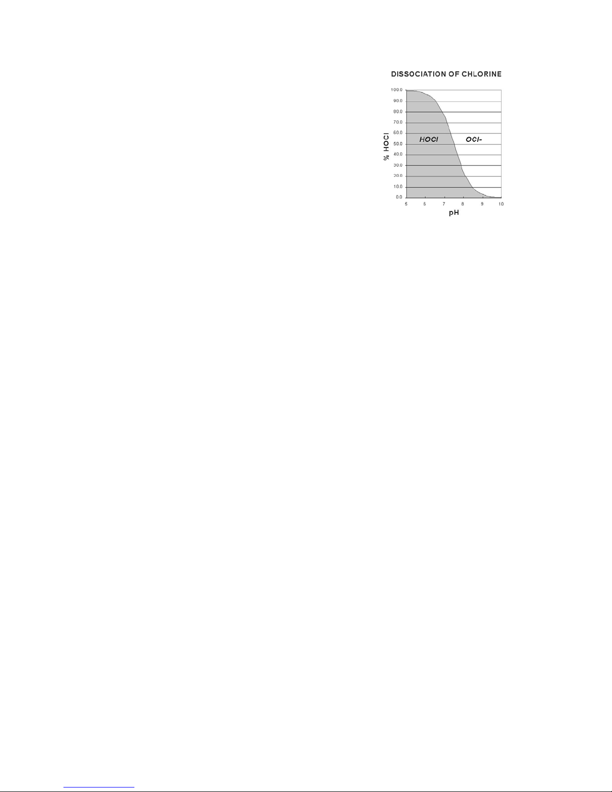
As shown on Figure 1, Free Chlorine in water is in equilibrium
under two forms:
• Molecular HOCl, a strong sanitizer and oxidizer,
• Ionized OCl-, a weak sanitizer and oxidizer.
At a pH of 7.5, the two forms are in equal proportions of 50%
each. At lower pH values, HOCl predominates. At higher pH
values, OCl- is dominant.
ORP CONTROL (Models 230/250)
The ORP sensor shows the voltage (in mV) produced by
oxidizers in water.
It responds to strong oxidizers, such as HOCl and its bromine
equivalent HOBr. It also responds to other strong oxidizers that
are used in water treatment, such as Ozone (O3) or Potassium
Monopersulfate (KSO3).
Because HOCl is the primary oxidizer, the signal of the ORP
sensor decreases with increasing pH values.
®
255 PPM/pH Controller,
®
250 ORP/pH Controller,
®
240 pH Controller,
®
235 PPM Controller.
®
230 ORP Controller.
Figure 1 - Equilibrium of Free Chlorine
The Free Chlorine display does not vary up to a pH of 7.8.
The PPM setpoint default value on the controller is 1.0 ppm,
which is recommended to kill germs and bacteria and maintain
good water quality. It can be adjusted to meet local conditions
and Health Department requirements.
WATER CHEMISTRY
Before starting automatic control, test the water chemistry to
make sure that the pH, Cyanuric Acid and Total Dissolved Solids
are within the ranges recommended by the National Spa and Pool
Institute (NSPI).
The pH should be adjusted manually within 7.4 to 7.6. If it is
below 7.0 or above 8.0, the controller will show an alarm condition
and prevent feeding (programmable option).
To stabilize chlorine against solar UV radiation, a cyanuric acid
level of 20 to 25 ppm is ideal. However, this level can be quickly
exceeded with stabilized chlorine (dichlor or trichlor). Note that
many Health Department codes do not allow stabilizer levels
above 100 ppm. If above 100 ppm, this results in chlorine lock
that shows as low ORP readings even with high chlorine levels.
It is not specific to chlorine or bromine and responds to other
oxidizers.
The chlorine or bromine concentration required to generate a
desired ORP value varies with pH and overall water quality,
particularly Total Dissolved Solids (TDS) concentration, organic
load and cyanuric stabilizer concentration.
The ORP setpoint default value on the controller is 700 mV,
which is recommended to kill germs and bacteria and maintain
good water quality.
PPM CONTROL (Models 235/255)
The PPM sensor is specific to Free Chlorine only.
The controller displays the concentration of Total Free Chlorine
(HOCl + OCl-) in PPM (parts per million or milligrams/liter). It
does not respond to Bromine and/or oxidizers.
The Total Dissolved Solid (TDS) level should be below 2,000
ppm. If higher, the water is full of organic and inorganic
impurities and should be dumped and replaced partially or
completely.
For effective pH control, the Total Alkalinity should be between
80 to 120 ppm. If too low, the pH will bounce and be hard to
control. If too high, the pH will be hard to change.
INPUTS AND OUTPUTS
Depending on the model number, the inputs include one or two
sensors:
• a PPM sensor to monitor free chlorine concentration,
• an ORP sensor to monitor ORP or Redox,
• a pH sensor and a safety flow switch (optional).
The outputs are two relays for sanitizer and pH feed - acid or
base - plus a relay for an optional remote alarm or telephone
dialer.
MAN250/04 Page 4
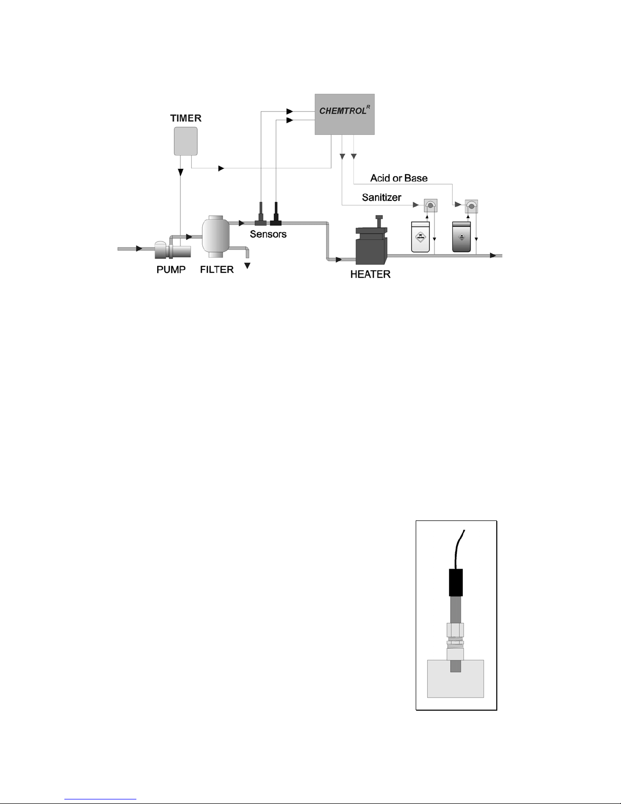
INSTALLATION
Figure 2 - Installation with Sensors on Main Line
LOCATION
Mount the controller cabinet as shown in Figure 2 on a wall in a
secure location:
• more than 10' (3 m) away from the water edge to
comply with electrical code requirements,
• if possible, not more than 10' (3 m) of the main
recirculation line or of the bypass line. The sensors
come with standard 10-foot (3-m) cables. If needed,
you can order 25 or 50-ft BNC extension cables from
your dealer.
• not exposed to direct sunlight,
• easily accessible to maintenance personnel,
• if possible in a separate room, or in a well- ventilated
room as far away as possible from corrosive chemicals
and storage tanks,
• at a safe distance from power transformers, pump
motors or high voltage power lines
• safe from unauthorized access or vandalism.
SENSOR INSTALLATION
Save the sensor caps for storage or shipping of the sensors.
When in storage or shipping, add salt water in the cap to keep the
sensors from drying out. During winter, store the sensors above
freezing temperature.
MAIN LINE INSTALLATION
On smaller installations (2 “ pipe diameter), the sensors can be
mounted directly on the main recirculation line (Figure 2).
Use only the 2x2x1/2 in. SST reducing tees without reducers
(Figure 3). Do not install the sensors near an elbow or a
constriction where there might be excessive turbulence.
Install the tees after the pump and filter. Insert the sensor tip
down so that the tip is about 1/4 inch (1 cm) in the water. The
sensors should be readily accessible for servicing but not
exposed to physical damage.
Tighten the compression fitting by hand only to avoid breaking the
internal glass tube in the sensors. Do not use a wrench!
The sensors can be mounted three different ways:
• directly on the main recirculation line (Figure 2) (2 in.
pipe only),
• on a 1/2 in. bypass line as shown Figure 3,
• even better, in a sensor cell mounted on the bypass line
(Figure 5).
Figure 3 - Sensor in PVC Tee
 Loading...