

Page 1

OPERATIONS MANUAL
SCC3500XRD
SCM2500XRD
Streaming Current Monitor &
Streaming Current Controller
with Dura-Trac
R 4 8/2/06 RA
™
Remote Sensor
Page 2

Page 3

TABLE OF CONTENTS
Section Title Page
IMPORTANT INSTRUCTIONS .......................................................................... 4
WARRANTY INFORMATION............................................................................. 5
1.0 GENERAL INFORMATION................................................................................ 6
1.1 Description of Operation ............................................................................ 6
1.2 Selecting Proper Sample Point .................................................................. 6
1.3 Process Control Procedures ...................................................................... 8
1.4 System Components ................................................................................. 9
1.5 Technical Specifications ............................................................................ 10
2.0 MOUNTING AND INSTALLATION..................................................................... 12
2.1 Mounting Location ..................................................................................... 12
2.2 Power Requirement ................................................................................... 12
2.3 Signal Wiring ........................................................................................ 14
2.4 Sample Connection ................................................................................... 15
2.5 Sensor Flush Options ................................................................................ 16
2.5.1 Dura-Trac with Flush ....................................................................... 16
2.5.2 Sensor Maintenance Module ........................................................... 17
3.0 OPERATION ........................................................................................ 19
3.1 Monitor/Controller User Interface............................................................... 19
3.2 SCM2500XRD Readout, Menus and Controls ........................................... 20
3.2.1 SCM2500XRD Main Screen ........................................................... 20
3.2.2 SCM2500XRD Setup Menu (1)........................................................ 21
3.2.3 SCM2500XRD Setup Menu (2)........................................................ 22
3.2.4 SCM2500XRD Alarm Status Menu .................................................. 23
3.2.5 SCM2500XRD Flush Control Menu ................................................. 24
3.3 SCC3500XRD Readout, Menus, and Controls........................................... 24
3.3.1 SCC3500XRD Main Screen ............................................................ 24
3.3.2 SCC3500XRD Setup Menus............................................................ 25
3.3.3 SCC3500XRD Alarm Status Menu .................................................. 26
3.3.4 SCC3500XRD Pump Control (1) Menu............................................ 27
3.3.5 SCC3500XRD Pump Control (2) Menu............................................ 29
3.3.6 SCC3500XRD Flow Control (3) Menu.............................................. 29
3.3.7 SCC3500XRD Flush Control Menu.................................................. 31
3.4 System operation....................................................................................... 33
3.5 Treatment Optimization Procedure ............................................................ 34
3.6 Manual Control Using Controller ................................................................ 35
3.7 Automatic Control ...................................................................................... 35
3.8 Automatic Control Setup............................................................................ 38
3.9 Flow Control ........................................................................................ 38
3.10 Tuning Constant Specifications ................................................................. 39
4.0 GENERAL GUIDELINES ................................................................................... 41
4.1 Streaming Current Value Response Factors.............................................. 41
4.2 Fundamental Streaming Current Knowledge ............................................. 42
Page 2
Page 4

TABLE OF CONTENTS (Continued)
Section Title Page
5.0 TROUBLESHOOTING GUIDES......................................................................... 45
6.0 MAINTENANCE PROCEDURES ....................................................................... 47
6.1 Replacement Procedures .......................................................................... 47
6.2 Cleaning Procedures ................................................................................. 47
6.3 Replacement Parts .................................................................................... 48
6.4 Ordering Information.................................................................................. 50
7.0 Mechanical Specifications............................................................................... 53
LIST OF FIGURES
Figure Title Page
1 Streaming Current Profile ................................................................................. 7
2 System Components ........................................................................................ 9
3 Monitor/Controller Power Wiring ....................................................................... 12
4 Dura-Trac Sensor Power Wiring ....................................................................... 13
5 Dura-TRAC II Sensor Power Wiring.................................................................. 13
6 Signal Wires Interconnection Diagram.............................................................. 14
7 Dura-TRAC Sensor Sample Connection ........................................................... 15
8 Dura-TRAC II Sensor Sample Connection ........................................................ 16
9 Dura-TRAC Sensor with Flush.......................................................................... 17
10 SMM Tubing Connections to Dura-Trac II Sensor............................................. 18
11 Automatic Flush Timing Diagram ...................................................................... 33
12 Dura-Trac Sensor Parts Identification ............................................................... 49
13 Dura-Trac II Sensor Parts Identification ............................................................ 50
14 Streaming Current Monitor/Controller Dimensions ............................................ 53
15 Dura-Trac Sensor Dimensions.......................................................................... 54
16 Dura-Trac II Sensor with SMM Dimensions....................................................... 54
17 Dura-Trac Sensor with Flush Dimensions ......................................................... 55
18 Dura-Trac II Sensor Dimensions....................................................................... 56
19 SMM Dimensions ........................................................................................ 56
Chemtrac Systems, Inc.
Page 3
Page 5

IMPORTANT INSTRUCTIONS
When using this instrument, basic safety precautions shall always be followed to
reduce the risk of fire, electrical shocks and injury to persons, including the
following:
R Before attempting to unpack, set up, or operate this instrument, please
read this entire manual.
R Make certain the unit is disconnected from the power source before
attempting to service or remove any component.
R Follow all warnings and marked on the instrument.
R Failure to follow these precautions could result in personal injury or
damage to the equipment.
R Do not attempt to disassemble the unit.
R Water must not be allowed to enter the housing of the unit.
R Close and fasten the covers of the unit prior to any external cleaning to
prevent water ingress.
R Do not drop or jar the unit.
R Do not modify any internal electrical wiring or electronics.
R Use a mild non-abrasive cleanser when cleaning the outer cover of the
unit.
SAFETY PRECAUTIONS
In order to provide maximum user safety this instrument was designed with all electrical
circuitry enclosed within a protective non-conductive housing. The label below will be
visible at any location where high voltage is present.
Chemtrac Systems, Inc.
Page 4
Page 6

WARRANTY INFORMATION
Chemtrac® Systems, Inc. warrants its equipment to be free from defects in
material and workmanship for a period of one (1) year from date of shipment to
the original purchaser. Upon receipt of written notice from purchaser, seller shall
repair or replace the equipment (at option of Chemtrac® Systems, Inc.).
Chemtrac® Systems, Inc. assumes no responsibility for equipment damage or
failure caused by:
1. Improper installation, operation, or maintenance of equipment.
2. Abnormal wear and tear on moving parts caused by some processes.
3. Acts of nature (i.e. lightning, etc.)
This warranty represents the exclusive remedy of damage or failure of
equipment. In no event shall Chemtrac® Systems, Inc. be liable for any special,
incidental, or consequential damage such as loss of production or profits.
Should you experience trouble with the equipment, please contact:
Chemtrac Systems, Inc
6991 Peachtree Industrial Blvd., Building 600
Norcross, GA 30092
Phone: 1-800-442-8722 (Inside US only), 770-449-6233
Fax: 770-447-0889
Email: chemtrac@chemtrac.com
Website: www.chemtrac.com
Chemtrac Systems, Inc.
Page 5
Page 7

SECTION 1.0 GENERAL INFORMATION
1.1 DESCRIPTION OF OPERATION
The Streaming Current Monitor/Controller includes a remote sensor module placed at
the desired sample point, and a Monitor/Controller module. The monitor is a chargemeasuring device. The charge that it measures is the net ionic and colloidal surface
charge (positive and negative) in the sample being tested. Streaming current is related
to zeta potential, however, they are not the same value.
The treated water sample flows into the sample cell where it is drawn into the bore
during the upstroke of the piston cycle and is expelled from the bore on the piston down
stroke. Particles contained in the water are temporarily immobilized on the piston and
cylinder surfaces. As the water is moved back and forth by the piston, charges
surrounding these particles (+ and -) are moved downstream to the electrodes. This
movement of like charges causes an alternating current to be generated, defined as
"streaming current." A signal gain selector, accessed through the menu screen, is used
to select the best signal amplification. The signal amplification should be set where a
normal change in dosage results in a desired deviation in streaming current (normally 30
units). The displayed streaming current value (SCV) should be considered as a relative
reading due to amplification of the primary signal.
The streaming current amplitude and polarity is a function of sampling location in the
treatment process. It is important to understand why the streaming current varies at
different points in the system to properly interpret the readings, therefore, Section 1.2
should be read very carefully.
1.2 SELECTING PROPER SAMPLE POINT
The sample must be taken at a point where uniform distribution and mixing of coagulant
is obtained for all flow rate conditions, and at a point that allows for a quick response to
chemical feed changes as measured by the monitor (i.e. after the rapid mixer or static
mixer, and before the slow mixer or flocculation basin). The lag time, or the amount of
time it takes the water to travel from the point of chemical addition to the sensor, should
be no greater than 3 minutes (30 seconds to 1.5 minutes are typical lag times). If
uniform distribution and mixing is not being obtained at a selected sample point, the
streaming current reading will oscillate. If the chemical is not being properly mixed
(indicated by an oscillating monitor reading), the sample point needs to be moved
further downstream away from the mixing device to allow the chemical more time to mix
in with the water. Under rare circumstances, moving the sample point further
downstream in order to obtain a more stable reading may result in a lag time longer than
3 minutes. Steps should be taken to improve chemical mixing under these conditions.
When possible, avoid sampling from places where sludge, grit, etc., will be drawn into
the sensor sample cell. Sample lines must be sized to provide velocities that will
prevent floc/sludge accumulation. Keep sample lines as short as possible to minimize
delay in response time.
Figure 1, Streaming Current Profile, normally observed in a typical water plant. When
coagulant is added to raw water, the charge neutralization process begins immediately.
The time required for this neutralization process to go to completion is primarily a
function of mixing, time, raw water characteristics, type of coagulant, and to a lesser
Chemtrac Systems, Inc.
Page 6
Page 8

degree, temperature. Untreated raw water has a net negative charge. Cationic
coagulant charges, (alum, polymer, etc.) can produce a net positive streaming current
early in the system. As shown on the graph, this current becomes less positive as
negative charges react with the coagulant. At the settling basin outlet, the streaming
current value can return to nearly the same as raw water. If raw water flow or sample
flow rate is increased, the total time for the sample to travel from point of coagulation
injection to the cell is decreased. This may cause a change in monitor reading (in the
positive direction), even though the coagulant dosage (PPM) remains constant.
Conversely, if raw water or sample flow rate is decreased, streaming current readings
may go more negative. Plants that have a shifting set point caused by wide swings in
raw water flows can minimize this effect by moving the sample point further
downstream, lengthening sample line, or adding a detention pot. It is important to
maintain the sample flow at +/- 10% of the rate initially set.
Based upon the above discussion, the proper sample point for a specific plant depends
upon the following conditions:
1. Point or points of coagulant feed.
2. Mixing efficiency of raw water and coagulant.
3. Magnitude of raw water flow swings.
4. Type and quantity of coagulants used.
Chemtrac Systems, Inc.
FIGURE 1. Streaming Current Profile
Page 7
Page 9

1.3 PROCESS CONTROL PROCEDURES
Model SCC3500XRD Only
In order for the monitor to be used for automatically controlling the coagulant feed
(alum, polymer, ferric chloride), the following guidelines must be followed:
1. The coagulant must be thoroughly mixed with the raw water by the time the
sample is taken.
2. “Lag time” (i.e., the time it takes for the monitor to see a change in coagulant
feed) should be no greater than 5 minutes.
3. Variability in sample flow rates should be no greater than +/- 10 % of the initial
rate.
4. Coagulant pumps must be kept in good mechanical condition to respond quickly
and accurately to process changes.
5. Raw water quality should be in a stable condition (turbidity, pH, color, etc. should
not change rapidly or widely) when setting up the system.
The monitor should be operated a few days in manual control to observe how it
responds to normal process operation. Recording streaming current changes on a strip
chart recorder is very helpful in anticipating factors that may have to be dealt with when
automatic control is started. This period, if using the monitor with a recorder for
monitoring, is also a good time to determine the optimum coagulant dosage and
establish the operating “setpoint”. This enables the system to be put on automatic
control very simply.
Chemtrac Systems, Inc.
Page 8
Page 10

1.4 SYSTEM COMPONENTS
The SCM2500XRD and SCC3500XRD system include the following:
q Monitor/Controller
q Dura-Trac Remote Sensor
q Dura-Trac Remote Sensor with Flush (Optional)
q Dura-Trac II Remote Sensor (Optional)
q Sensor Maintenance Module (Optional)
Figure 2 illustrates system components.
MONITOR/CONTROLLER
SCC3500XRD
Power
Service
Diag.
Alarm
CHEMTRAC
SYSTEMS, INC.
SEMSOR MAINTENANCE MODULE
DURA-TRAC SENSOR OR DURA-TRAC SENSOR WITH FLUSH
CHEMTRAC
SYSTEMS, INC.
PATENTED MADE IN U.S.A.
DURA-TRAC
TM
CHEMTRAC
SYSTEMS, INC.
PATENTED MADE IN U.S.A.
DURA-TRAC
TM
DURA-TRAC II SENSOR
Chemtrac Systems, Inc.
CHEMTRAC
SYSTEMS, INC.
TM
PATENTED MADE IN U.S.A.
DURA-TRAC II
FIGURE 2. System Components
Page 9
OPERATOR
MANUAL
Page 11

1.5 TECHNICAL SPECIFICATIONS
MONITOR/CONTROLLER
Power ...................................... 85-264 VAC, 47–63 Hz
Current Load ........................... 110 VAC @ 0.5A Max
220 VAC @ 0.25A Max
User Interface.......................... Backlit Liquid Crystal Display, Menu Driven Functions,
Keypad Interface
SCV Readout .......................... -1000 to +1000
Resolution ............................... Streaming Current Units
Signal Gain.............................. User Adjustable 1X to 20X
Zero Offset .............................. Automatic, Full Scale All Ranges
Accuracy ................................. 0.5% of Full Scale
Response Time ....................... 1 Second
SCV Output Signal .................. Standard 4-20 mA (300 ohm Load)
Optional 0-10 VDC
Alarm Output ........................... 24 VDC (Solid State Relay Optional) and Auditable
Alarm for Sensor Status, High/Low Streaming Current
Value and High/Low Pump Output - SC3500XRD Only
Digital Input ............................ Dry Contacts
Enclosure Type ....................... NEMA 250 Type 4X, Reinforced Fiberglass
Enclosure Size ........................ 9.2”W, 11.2”H, 6.3”D (234mm W, 285mm H, 161mm D)
Mounting Holes ....................... 11.25”W, 7.4”H (286mm W, 188mm H)
Weight..................................... 6 Pounds (2.72 kg)
Control Output Alarms............. Adjustable High/Low Alarms
Operating Temperature ........... 32° F to 120° F (0° C to 49° C)
Following Parameter are for SCC3500XRD Only
PID Tuning Parameters........... Proportional Gain: Range 0-1000
Integral Time: Range 0-1000
PID Rate: Range 1-20
SmartTrac PID Control ............ SCC3500XRD Only
Analog Input ............................ 4-20 mA
Control Output Signal .............. 4 – 20 mA (300 Ohm Load) or 0 – 10 VDC
Control Output Limits............... Adjustable High/Low Limits
Dura-Trac REMOTE SENSOR
Power ...................................... 115 VAC, 60 Hz (standard)
230 VAC, 50 Hz (optional)
Sample Flow Rate ................... 5.0 GPM
Sample Cell Type .................... External Receiver, High Flow
Probe Type.............................. Quick Replacement Cartridge
Water Sample Connections..... Inlet: 3/4” O.D. Barb Type, Outlet: 1” O.D.
Materials Contacting Sample... Delrin, Nylon, Neoprene Viton, PVC, Stainless Steel
Chemtrac Systems, Inc.
Page 10
Page 12

Dura-Trac REMOTE SENSOR (Continue)
Output Wiring .......................... 4 Conductors Twisted Shielded Pair, 20 AWG
(6 Conductors Twisted Shielded Pair with Flush Option)
Enclosure Type ....................... NEMA 250 Type 4X, Reinforced Fiberglass
Enclosure Size ........................ 11.2”W, 9.2”H, 6.3”D (285mm W, 234mm H, 161mm D)
Mounting Holes ....................... 7.4” W, 11.25” H (188mm W, 286mm H)
Overall Height with Sensor ...... 14.7’’ (373mm)
Weight..................................... 10 Pounds (4.5 kg)
Operating Temperature ........... 32° F to 120° F (0° C to 49° C)
Dura-Trac WITH FLUSH (OPTION):
Flush Water Connections ........ ¼’’ Quick Connect Tube Fitting, Adaptable
Flush Water Pressure…. ......... 35 to 80 PSI
Overall Height with Sensor ...... 17.6’’ (447mm)
Dura-Trac II REMOTE SENSOR
Power ...................................... 115 VAC, 60 Hz (standard)
230 VAC, 50 Hz (optional)
Sample Flow Rate ................... 10 GPM
Sample Cell Type .................... External Receiver, High Flow
Probe Type.............................. Quick Replacement Cartridge
Water Sample Connections..... Inlet: 3/4” O.D. Barb Type, Outlet: 1-1/2” O.D.
Materials Contacting Sample... Delrin, Nylon, Neoprene Viton, PVC, Stainless Steel
Output Wiring .......................... 4 Conductors Twisted Shielded Pair, 20 AWG
(6 Conductors Twisted Shielded Pair with Flush Option)
Enclosure Type ....................... NEMA 250 Type 4X, Reinforced Fiberglass
Enclosure Size ........................ 11.2”W, 9.2”H, 6.3”D (285mm W, 234 mm H, 161mm D)
Overall Height with Sensor ...... 18.8’’ (477mm) without SMM Option
21.8’’ (554mm) with SMM Option
Mounting Holes ....................... 9.7”W x 10.5”H (247mm W x 266mm H)
Weight..................................... 15 Pounds (6.8 kg)
Operating Temperature ........... 32° F to 120° F (0° C to 49° C)
SENSOR MAINTENANCE MODULE (OPTIONAL)
Power ...................................... 24 VDC (Supplied From Monitor)
Flush Water Connections ........ ¼’’ Quick Connect, Adaptable
Flush Water Inlet PSI .............. 35 to 80 PSI
Chemical Injection Pump......... 1,000 mL/min (Max)
Outlet Connection.................... ¼’’ Quick Connect, Semi Rigid Tubing
Enclosure Type ....................... NEMA 250 Type 4X, Reinforced Fiberglass
Module Size ............................ 11.2”W, 9.2”H, 6.3”D (285mm W, 234 mm H, 161mm D)
Mounting Holes ....................... 9.7”W x 10.5”H (247mm W x 266mm H)
Weight..................................... 6 Pounds (2.72 kg)
Chemtrac Systems, Inc.
Page 11
Page 13

SECTION 2.0 MOUNTING AND INSTALLATION
2.1 MOUNTING LOCATION
The sensor can be located several hundred feet from the monitor. The sensor must be
mounted in a vertical position with the sample flowing into the inlet (3/4” barb fitting) and
exiting from the outlet (PVC elbow). Typically, the sensor is mounted as closely as
possible to the sampling point. Minimizing sample line lengths provides quicker
response to process changes. Sample may be obtained by using a sample pump,
tapping off a pressurized line, or using gravity feed system to get sample to the sensor.
The sample flow rate should not exceed 5.0 GPM for Dura-Trac sensor and 10.0 GPM
for Dura-Trac II sensor. Draining to atmosphere (unobstructed) is required; a
closed pipe (pressurized) drain is not recommended.
The Monitor/Controller module should be installed in a location, which will allow regular
viewing of the display as well as easy access to the front panel menu keys. See
Mounting Dimension Diagrams at end of Manual.
2.2 POWER REQUIREMENT
Electrical power should be connected in the following order
R Insert the ground wire into the middle terminal labeled “G”.
R Insert the hot wire into the left terminal labeled “L”.
R Insert the neutral wire into the right terminal labeled “N”.
For safety and proper operation, the monitor must be properly grounded through their
power cord. In cases where potential noise sources could affect the performance of the
equipment, a "surge suppressor" must be installed with the unit. The following drawings
show power terminal connections for models SCM2500XRD and SCC3500XRD
monitors, and Dura-Trac or Dura-Trac II Sensor.
Figures 3 thru 5 illustrate power-wiring connections to Monitor/Controller, Dura-Trac,
and Dura-Trac II Sensors.
FUSE: AGC-1.5A
Chemtrac Systems, Inc.
FUSE
WARNING TURN POWER OFF BEFORE MAKING ANY WIRE CONNECTIONS
TO AVOID DAMAGING THE ELECTRONIC CIRCUIT.
OFF
ON
G
L N
L
N
GND
POWER CORD
SMM | Sensor
*
*
*
*
*
1
432 65
FIELD WIRING TERMINALS
8 9 1311 12 1514 16
7
10
181719 20
FIGURE 3. Monitor/Controller Power Wiring
Page 12
Page 14

6543
1
2
119 10 1287
Opto (W)
Opto (O)
+24 Vdc
Opto (B)
+ Probe
Vdc Gnd
Cond.
High
- Probe
Shield
Signal
Opto
L1
N
FIGURE 4. Dura-Trac Sensor Power Wiring
543
1
2
6 119 10 1287
Opto (W)
Opto (O)
+24 Vdc
Vdc Gnd
Opto (B)
Cond.
+ Probe
High
- Probe
Shield
Signal
Opto
L1
N
FIGURE 5. Dura-TRAC II Sensor Power Wiring
Chemtrac Systems, Inc.
Page 13
Page 15

2.3 SIGNAL WIRING
The Dura-Trac and Dura-Trac II Sensors transmit the sensing signal to
Monitor/Controller by a multi conductor wires, see Figure 7 for signal wires
interconnection diagram. Twisted shielded cable should be used. The cable should be
enclosed in conduit for maximum protection against damage or electrical interference.
Do not run cable in same conduit with any other wiring.
R Make sure the monitor’s power switch is turn to off position before making any
signal wiring connections.
FUSE
FUSE: AGC-1.5A
OFF
ON
GL N
WARNING TURN POWER OFF BEFORE MAKING ANY WIRE CONNECTIONS
TO AVOID DAMAGING THE ELECTRONIC CIRCUIT.
1
2
3
4
5
6
7
SMM | Sensor
8
CAUTIONS
1817 19 20
9
10
11
12
13
14
15
16
*
*
*
*
1
32 4
17
18
19
*
8657
920121110
16151413
L
N
GND
(BLACK)
(RED)
(WHITE)
(BLUE)
1
+24 Vdc
Vdc Gnd
Signal +
Signal -
5432
Shield
6 87 9
+ Probe
- Probe
Opto (O)
Opto (B)
10
Opto (W)
(BLACK)
(BROWN)
(RED)
(WHITE)
64 5321 12111087 9
CHEMICAL PUMP
FLUSH VALVE
SAMPLE ISO VALVE
24 VDC COMMON
FIGURE 6. Signal Wires Interconnection Diagram
Chemtrac Systems, Inc.
Page 14
Page 16

2.4 SAMPLE CONNECTION
Sample shall be connected to the sample cell inlet side. A 3/4" barbed fitting connection
is provided for hose connection. The PVC elbow opposite the inlet is the outlet. The
outlet sample must flow to an open drain (sample receiver). The cell cannot operate
properly if pressurized. Do not replace either fitting with any other type of fitting.
Start treated water sample through the cell at a rate of between 1 to 5 GPM. Make sure
the outlet is free of obstructions. Continuous reliability of the sample flow is essential.
Interruption of the sample flow will result in erroneous readings on the
Monitor/Controller. For Controller model SCC3500XRD operating in AUTO mode, loss
of flow to the Dura-Trac sensor will result in improper coagulant dosing. A suitable flow
alarm is recommended for maximum reliability.
On the SCC3500XRD, the pump control output of the controller must be set in the
MANUAL mode if the sensor is flushed or cleaned or if power to the sensor is
interrupted for any reason. The controller can be placed back in AUTO once power
and sample flow is restored. For system with Dura-Trac with flush with Sensor
Maintenance Module (SMM), during Automatic Flushing cycles, the pump control
output signal is maintained at a constant value (see Flush Menu).
IMPORTANT
PATENTED MADE IN U.S.A.
SAMPLE OUTLET
PVC Drain
Funnel
4" Cup
DURA-TRAC
TM
SAMPLE INLET
3/4" BARB FITTING
FIGURE 7. Dura-TRAC Sensor Sample Connection
Chemtrac Systems, Inc.
2" Line
Page 15
Page 17

CHEMTRAC
SYSTEMS, INC.
DURA-TRAC II
PATENTED MADE IN U.S.A.
SAMPLE INLET
3/4" BARB FITTING
FIGURE 8. Dura-TRAC II Sensor Sample Connection
2.5 SENSOR FLUSH OPTIONS
The SCM2500XRD and SCC3500XRD are available with one of two options for
automatic sensor flushing/cleaning. The first option is the Dura-Trac with flush and is
composed of a valve mounted onto the Dura-Trac sensor, which is connected to flush
water. The second option is the SMM and is composed of a flush valve, sample
isolation valve, and chemical injection pump. The Dura-Trac with flush is recommended
for Drinking Water applications where high turbidity is often experienced. The SMM is
recommended for Waste Water applications. These options are only supplied if
specified at the time of purchase. The line of monitors offered by Chemtrac® can be
upgraded to include one of these two options. To upgrade to the Dura-Trac with either
options, the Dura-Trac sensor will need to be returned to the factory.
Potable water or the best quality plant water available shall be used for the flush water
supply. If potable water is used for flush water, a backflow prevention device should be
installed on the flush water line to prevent contamination of the potable water source.
The flush water needs to maintain a pressure of 35 PSI min to 80 PSI max.
2.5.1 Dura-Trac with Flush
Connect the male NPT end of the ¼’’ MNPT to ¼’’ Quick Connect Tube adapter fitting
(supplied with the unit) to the flush water supply. Connect a sufficient length of ¼’’
Teflon tubing between the flush water supply (¼’’ Quick Connect Tube adapter fitting)
and the valve’s ¼” quick connect fitting (see Figure 10 on the next page). The flush
valve’s outlet should already be connected to the probe flush assembly. The third valve
outlet (located on the bottom of the valve and pointed towards the ground) is the drain
outlet. Run this outlet to an appropriate drain using ¼’’ semi-rigid tubing. A manual
control valve should be installed on the flush water line in close proximity of the unit so
TM
SAMPLE OUTLET
45 DEGREE ELBOW
4" Cup
2" Line
PVC Drain
Funnel
Chemtrac Systems, Inc.
Page 16
Page 18

that the flush water may be shut off during sensor maintenance. Do not open flush
water supply valve until all connections have been made.
CHEMTRAC
SYSTEMS, INC.
PATENTED MADE IN U.S.A.
25 PSI
CHECK
VALVE
FIGURE 9. Dura-TRAC Sensor with Flush
2.5.2 Sensor Maintenance Module
Figure 11 show tubing connections between SMM and Dura-Trac II sensor. The semirigid Teflon tubing is supplied with the unit.
u Connect an appropriate length of ¼’’ semi-rigid Teflon tubing between the
PINCH VALVE outlet quick connect fitting on the SMM and the PINCH VALVE
assembly quick connect fitting.
DURA-TRAC
TM
FLUSH WATER
CONNECTION
1/8" NPT TO 1/4"
COMPRESSION
FLUSH VALVE
v Connect the male NPT end of the ¼’’ MNPT to ¼’’ Quick Connect Tube adapter
fitting to the flush water supply. Connect a sufficient length of ¼’’ Teflon tubing
between the flush water supply (1/4’’ Quick Connect Tube adapter fitting) and
the SMM’s flush water inlet ¼’’ quick connect fitting. A manual control valve
should be installed on the flush water line in close proximity of the unit so that the
flush water may be shut off during sensor maintenance. Do not open flush water
supply valve until all connections have been made.
w Connect an appropriate length of ¼’’ semi-rigid Teflon tubing between the
PROBE FLUSH outlet quick-connect fitting on the SMM and the PROBE FLUSH
assembly quick connect fitting on the Dura-Trac II Sensor.
x Connect an appropriate length ¼’’ semi-rigid Teflon tubing between the
“Chemical Rinse” PUMP INLET quick connect fitting on the SMM and the
chemical carboy.
Chemtrac Systems, Inc.
Page 17
Page 19

y Connect an appropriate length ¼’’ semi-rigid Teflon tubing between the
“Chemical Rinse” PUMP OUTLET quick connect fitting on the SMM and the and
the Dura-Trac II chemical injection port.
The SMM has a drain port on the bottom of the unit. If the drain port needs to be
extended, connect an appropriate length of ¼’’ semi-rigid Teflon tubing between the
SMM Drain quick-connect fitting to the nearest drain.
During the automatic flush/cleaning cycle, the chemical pump injects a cleaning solution
into the sensor. This cleaning solution prevents the buildup of fouling agents, which can
overtime affect the sensitivity and response of the instrument. Periodic checks of the
chemical carboy should be made to ensure the chemical storage tank is at least 1/4 full.
CAUTIONS
R Acid concentration shall not exceed 15% concentration.
SENSOR
MAINTENANCE
MODULE
(SMM)
CHEMTRAC
SYSTEMS, INC.
PATENTED MADE IN U.S.A.
PINCH VALVE
TM
DURA-TRAC II
25 PSI
CHECK
VALVE
DURA-TRAC II
SENSOR
CARBOY
TANK
FIGURE 11. SMM Tubing Connections to Dura-Trac II Sensor
Chemtrac Systems, Inc.
Page 18
Page 20
SECTION 3.0 OPERATION
3.1 MONITOR/CONTROLLER USER INTERFACE
The Monitor/Controller is equipped with user interface keys, LED indicators, and audible
beeps. The interface keys are up (p), down (q), left (t), right (u), and function keys.
There are four LED lights to the left of the graphical display. These are:
The Monitor/Controller provides the user with an audible beep feedback every time a
button is pressed.
The menu navigation of the Monitor/Controller is by using buttons at the front panel.
The following steps explain general menu navigations.
t = LEFT key
q Power –Green LED that illuminates when there is power to the unit.
q Service - Yellow LED displays the status of the electronics.
q Diag. – Green LED that blinks to give a diagnostic status of the remote sensor.
u
== RRIIGGHHTT kkeeyy
u
When this LED stops blinking, the remote sensor diagnostic alarm is in alarm
condition.
q Alarm – Red LED that illuminates when the Monitor/Controller is in alarm condition.
1. From the MAIN screen, pressing any function key will gain access to other
menu screens.
2. At the menu screen, on the far left hand side of the text there is a text cursor (})
that indicates the active line on the menu. By pressing the p or q key, the text
cursor will move to a different menu text line.
3. To modify the parameter setting on the active menu text, first press the u key
to gain access to the parameter and then press the p or q key to scroll
through the parameter range. By holding down the p or q key, the number will
increased or decreased with larger unit changes.
4. When finished making the parameter change, press t key to store the value.
At this point, the new parameter has not been saved. After all parameters
modification are completed, press the SAVE function key to accept the change
or press the MAIN function key to discard the changes.
p = UP key
q = DOWN key
Graphically define function
keys. Acsess by pressing on
button directly below.
Chemtrac Systems, Inc.
Page 19
Page 21

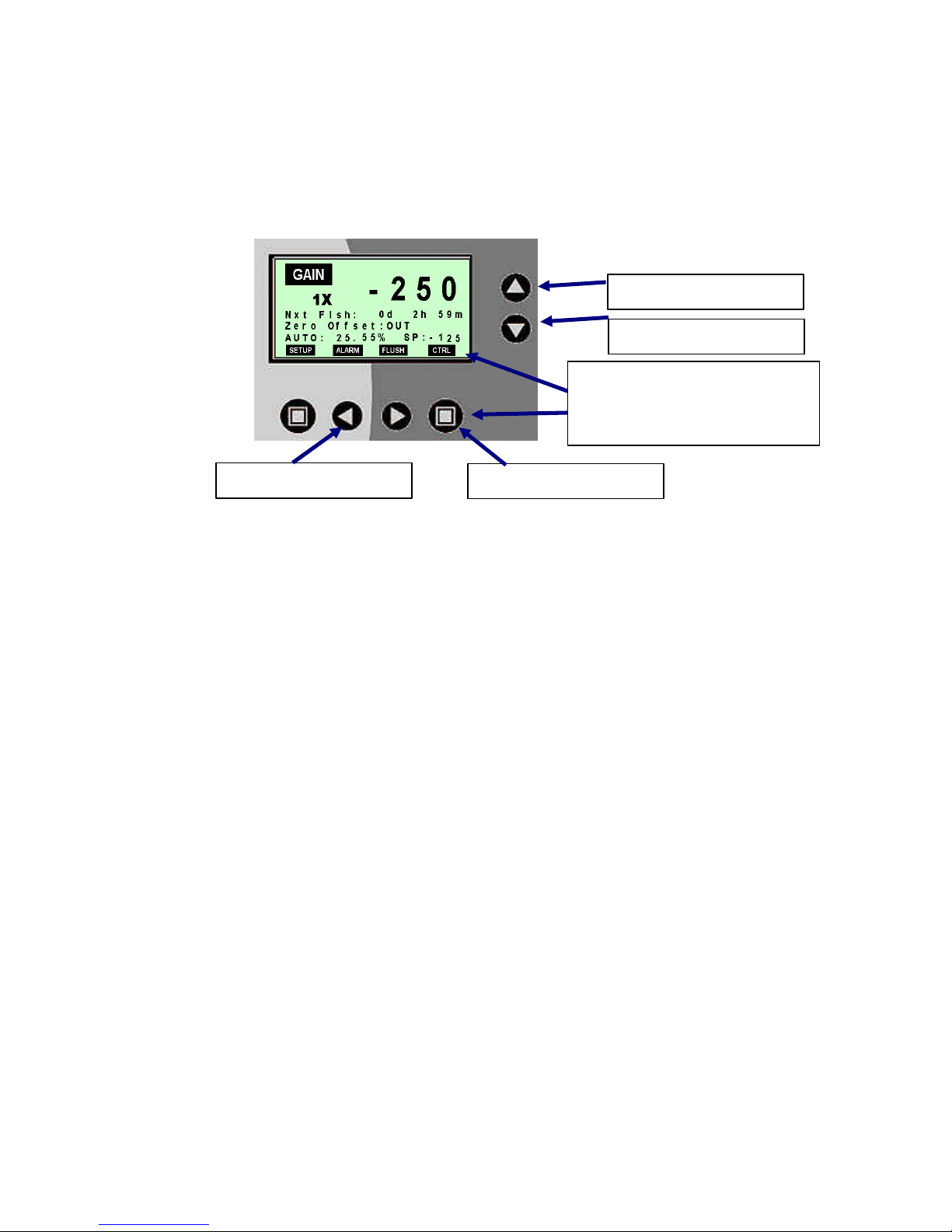
3.2 SCM2500XRD READOUT, MENUS, AND CONTROLS
The menu system for the SCM2500XRD is simple to navigate, below you will find the
different screens accessible through the function keys (SETUP, ALARM, and FLUSH):
3.2.1 SCM2500XRD Main Screen
The MAIN screen on the SCM2500XRD is the screen used under normal operation of
the instrument. From this screen, all other features and menus can be accessed. The
menu screen shows with Flush option.
v
u
u
w
x
y
Definitions
Streaming Current Value (SCV) ranges from –1000 to +1000
u
Gain, signal amplification factor, adjustable from 1X to 20X
v
Next Flushing Cycle (optional): If the unit include sensor flush feature, the
w
menu display the time when the next flush will occur in days, hours, and minutes.
x
Offset: OUT Offset condition OUT, actual SCV is display
Offset Value: -1000 to +1000
Zero Offset Conditions
Offset: IN Offset condition IN, adjusted SCV is displayed and the actual
SCV value will be display to the right of OUT.
The Offset function is used to automatically zero the current reading. Once an
optimum chemical dosage has been obtained, the user can null the reading so
that the setpoint becomes referenced to zero for easier interpretation (see Setup
Screen Menu).
Function Keys – There are four main menu selections across the bottom for the
y
four buttons below. The four menus are:
SETUP – SCV Setup Menu
ALARM – Alarms Status
FLUSH – Sensor Flush Control Menu
Pressing one of these keys directly below these menu selections accesses the
functions within that menu.
Chemtrac Systems, Inc.
Page 20
Page 22

3.2.2 SCM2500XRD Setup Menu (1)
From the MAIN screen, press SETUP function key, the SETUP screen will display.
Within the SETUP screen menu, the GAIN, OFFSET, and SCV ALARMS settings can
be modified.
u
v
w
x
y
z {
“
Definitions
u Sensor Gain: Signal amplification factor, adjustable from 1X to 20X. The gain
should be adjusted so that a regular change in dosage results in a noticeable
deviation (e.g. 20 to 30 units). To select the proper gain setting let the reading
stabilize for 10 minutes and record the reading. Make a normal dosage change
and then allow another 5 to 10 minutes for the reading to fully stabilize. If the
reading did not change noticeably, simply increase the gain setting and repeat
testing. If the reading changed, but did so by more than 50 units, it is suggested
to decrease the gain setting. Ideal change in Streaming Current for a normal
dosage change is anywhere between 20 to 50 units. If the reading seems
unstable when flow, dosage, NTU, and PH are stable, then check to ensure the
probe is clean and that the sensor is getting a well mixed sample.
v
w
Offset Mode: Offset mode can be changed to IN or OUT. Changing the Offset
mode to from “OUT” to “IN” will automatically zero or null the current Streaming
Current reading. For example, if the current reading was –150 and the Zero
Offset was changed to “IN”, then the adjusted Streaming Current value is
displayed on the Main Screen would be zero. The reading will not stay exactly at
zero since the reading is always slightly changing as a result of slight changes in
charge. The Offset value will display at the line below. On the Main Display, the
raw Streaming Current value (with offset) will be displayed to the right of the
Zero Offset: IN. The different between the Streaming Current value and the raw
is the offset value. To disengage the Offset, simply change the Offset mode to
“OUT” and the true Streaming Current Reading will be displayed.
Offset Value: The Offset value indicates the amount of offset that has been
applied to the reading in order to offset the reading to zero. So that, at any time
the operator can see what the offset value is and if anyone has changed it from a
previous offset. To disengage the offset, simply change the Offset Mode to
“OUT” and the true Streaming Current Reading will be displayed. This is also
the method used to re-zero the reading if the current offset no longer
corresponds to optimum coagulant feed. To re-zero the reading when Offset
mode is “IN”, increased or decreased the Offset Value then press Enter to
SAVE.
Chemtrac Systems, Inc.
Page 21
Page 23

SCV Lo (Low) Alarm - This is the streaming current low value alarm
x
(-1000 to +1000). This alarm should be set so that it correlates to a reading
which indicates an under dosage of chemical. Once properly set, if there is an
under dosage (or total loss) of chemical feed, the streaming current value will
drop below this alarm threshold and the alarm will be activated (meaning that the
Main Display will show “Alarm: On” and the Alarm Output will be engaged. Once
the streaming current value returns above the alarm threshold, the Alarm will
deactivate.
SCV Hi (High) Alarm - This is the streaming current high value alarm
y
(-1000 to +1000).and works the same way as the SCV Low alarm except this
alarm value should be set to correlate to a reading which indicates an over
dosage of chemical.
z
SCV AO Scale – The analog output’s scaling of the streaming current value can
be set for +/-1000, +/-750, +/-500, or +/-250. This setting allows the analog
output to change based on different scale settings.
{ MAIN Function Key – Pressing this key will ignore any setting modifications on
this screen and brings up the MAIN screen.
SAVE Function Key – Pressing this key will save current setting modifications
|
and brings up the MAIN screen.
3.2.3 SCM2500XRD Setup Menu (2)
From the SETUP MENU (1), continue pressing the down arrow key until SETUP MENU
(2) menu screen display. SETUP MENU (2) menu screen is a continuation of the
SETUP MENU (1) menu screen.
u v
Definitions
u
SCV Filter: The filter function activate rolling average of the Streaming Current
value over time. The SCV filter can be set to OFF, 30, 60, 90, or 120 seconds.
The default setting is OFF.
Chemtrac Systems, Inc.
Page 22
Page 24

3.2.4 SCM2500XRD Alarm Status Menu
From the MAIN screen, press ALARM function key, the ALARM STATUS screen will
display. Within the ALARM STATUS menu you can view which Alarm has been
triggered, as well as, turn the Monitor/Controller’s audible alarm feature on and off.
u
v
w
x
y
Definitions:
u Diagnostic: Display sensor diagnostic alarm condition. When the sensor is in
diagnostic alarm, it will show ALARM, the green LED (Diag.) will also stop
blinking, and the Streaming Current value will show “---“. Most likely cause for a
diagnostic alarm is that the motor in the
sensor is not turning. Check to ensure the
motor is turning. If the motor is turning,
ensure the blade of crank is passing cleanly
through the opto-switch. If the blade is
rubbing against the opto-switch, make an
adjustment by loosening the setscrew of the
crank and sliding it over so that the blade
lines up in the middle of the opto-switch. If the blade was rubbing, it will be
necessary to use compressed air to remove any debris (dust) that may be
blocking the optics of the opto-switch. Finally, check the interconnect wiring if no
other cause can be found for the diagnostic alarm. A loose connection or a
terminal that is screwed down on the insulation of the wire instead of the wire
itself can cause the diagnostic alarm to activate.
v
w
x
y
z
SCV Lo (Low): The SCV Lo Alarm indicates that the SCV fall below the SCV Lo
Alarm threshold.
SCV Hi (Low): The SCV Hi Alarm indicates that the SCV rises above the SCV
Hi Alarm threshold.
Dry Contact: Digital input status (normally open) indicates the state of digital
input. When digital input is close, the ALARM condition will display.
MAIN Function Key – Pressing this key will bring up the MAIN screen.
Audible Alarm Indication – The Monitor/Controller is equipped with audible
alarm feature. The audible alarm will beep and the red LED light will come on
when any alarm condition occurred. The Ù symbol will appear when the audible
alarm is enabled, see Special Function Key’s definition below to activate and
deactivate the audible alarm. There are two audible alarm sound lever; high and
low. When the audible alarm is enabled and alarm condition occurs, high-level
beep will be generated. The method of acknowledging the alarm is to press the
ALARM function from the MAIN screen, the alarm beep will switch to low level. If
any new alarms occur, the high-level beep will be generated to notify the user of
the new alarm.
z
z
{
{
Chemtrac Systems, Inc.
Page 23
Page 25

{
When any alarm is triggered, a +24 Vdc signal will be present on the Monitor’s digital
alarm output terminals. This signal can be connected to a SCADA/DCS system to alert
the operators to an Alarm condition. In lieu of a +24VDC signal, an optional solid state
relay output is available (must be specified with order).
After being properly adjusted by the operator to match up with the upper and lower SCV
readings that typically correlate to the acceptable window of process performance, the
Hi and Lo Alarms alert the operator as to whether the SCV has exceeded acceptable
limits. A Lo Alarm signify an underfeed of chemical (even possible loss of chemical
feed) and a Hi Alarm signify an overfeed.
3.2.5 SCM2500SRD Flush Control Menu
This flush feature is an option that is available for the SCM2500XRD, see Section 3.3.7
for detail description.
3.3 SCC3500XRD READOUT, MENUS, AND CONTROLS
The menu system for the SCC3500XRD is simple to navigate; below you will find the
different screens accessible through the function keys (SETUP, ALARM, FLUSH, and
CTRL). The menu screen shows with Flush option.
3.3.1 SCC3500 Main Screen
Special Function Key – The audible alarm can be toggled ON and OFF by
pressing both q and p keys. The Ù symbol will only appear when the audible
alarm is enabled. Once the audible alarm is disabled, the only way to enable is
to toggle with this Special Function key.
u
u
u
v
w {
{
{
x
y
z
Definitions
Streaming Current Value (SCV) ranges from –1000 to +1000
u
Gain, signal amplification factor, adjustable from 1X to 20X
v
Next Flushing Cycle (optional): If the unit include sensor flush feature, the
w
menu display the time when the next flush will occur in days, hours, and minutes.
x
Offset: OUT Offset condition OUT, actual SCV is display
Offset Value: -1000 to +1000
Zero Offset Conditions
Offset: IN Offset condition IN, adjusted SCV is displayed and the actual
SCV value will be display to the right of OUT.
Chemtrac Systems, Inc.
Page 24
Page 26

The Offset function is used to automatically zero the current reading. Once an
optimum chemical dosage has been obtained, the user can null the reading so
that the setpoint becomes referenced to zero for easier interpretation (see Setup
Screen Menu).
Coagulant Pump Control Mode
y
Mode: AUTO or MAN
PID Control Output: 0-100.00%
SP (Setpoint): SCV control setpoint (-1000 to +1000)
z
SETUP – SCV Setup Menu
ALARM – Alarms Status
FLUSH – Sensor Flush Control Menu
CTRL – Coagulant Pump Control and Flow Based Control Menu
Function Keys – There are four main menu selections across the bottom for the
four buttons below. The four menus are:
Pressing one of the keys directly below these menu selections accesses the
functions within that menu.
{ Special Function Key – For the coagulant pump control mode, the control mode
can be toggled between AUTO and MAN by pressing both q and p keys at the
same time. When AUTO is present, the instrument is operating in automatic
mode, sending a control signal to the coagulant pump. When MAN is present,
the instrument is operating in manual mode, sending a control signal to the
coagulant pump, which corresponds, to the manual value. The manual control
value can be changed by the operator by pressing the p or q key, see Section
3.7 for more detail.
3.3.2 SCC3500XRD Setup Menus
From the MAIN screen, press SETUP function key, the SETUP screen will display.
Within the SETUP screen menu, the GAIN, OFFSET, SCV ALARMS, and SCV Filter
settings can be modified. The SETUP Menus are the same for SCM2500XRD and
SCC3500XRD see Sections 3.2.2 and 3.2.3 for detail descriptions.
Chemtrac Systems, Inc.
Page 25
Page 27

3.3.3 SCC3500XRD Alarm Status Menu
From the MAIN screen, press ALARM function key, the ALARM STATUS screen will
display. Within the ALARM STATUS menu you can view which Alarm has been
triggered, as well as, turn the Monitor/Controller’s audible alarm feature on and off.
u |
v }
w
x
y
z
{
Definitions:
u Diagnostic: Display sensor diagnostic alarm condition. When the sensor is in
diagnostic alarm, it will show ALARM, the green LED (Diag.) will also stop
blinking, and the Streaming Current value will show “---“. Most likely cause for a
diagnostic alarm is that the motor in the sensor is not turning. Check to ensure
the motor is turning. If the motor is turning, ensure the blade of crank is passing
cleanly through the opto-switch. If the blade is rubbing against the opto-switch,
make an adjustment by loosening the setscrew of the crank and sliding it over so
that the blade lines up in the middle of the opto-switch. If the blade was rubbing,
it will be necessary to use compressed air to remove any debris (dust) that may
be blocking the optics of the opto-switch. Finally, check the interconnect wiring if
no other cause can be found for the diagnostic alarm. A loose connection or a
terminal that is screwed down on the insulation of the wire instead of the wire
itself can cause the diagnostic alarm to activate.
v
w
x
y
z
{
|
SCV Lo (Low): The SCV Lo Alarm indicates that the SCV fall below the SCV Lo
Alarm threshold.
SCV Hi (Low): The SCV Hi Alarm indicates that the SCV rises above the SCV
Hi Alarm threshold.
Pump Output Lo (Low): The Pump Output Lo Alarm indicates that the pump
output has exceeded the lower Alarm threshold.
Pump Output Hi (High): The Pump Output Hi Alarm indicates that the pump
output has exceeded the upper Alarm threshold.
Dry Contact: Digital input status (normally open) indicates the state of digital
input. When digital input is close, the ALARM condition will display.
MAIN Function Key – Pressing this key will bring up the MAIN screen.
Audible Alarm Indication – The Monitor/Controller is equipped with audible
alarm feature. The audible alarm will beep and the red LED light will come on
when any alarm condition occurred. The Ù symbol will appear when the audible
alarm is enabled, see Special Function Key’s definition below to activate and
deactivate the audible alarm. There are two audible alarm sound lever; high and
low. When the audible alarm is enabled and alarm condition occurs, high-level
beep will be generated. The method of acknowledging the alarm is to press the
|
|
}
}
Chemtrac Systems, Inc.
Page 26
Page 28

ALARM function from the MAIN screen, the alarm beep will switch to low level. If
any new alarms occur, the high-level beep will be generated to notify the user of
the new alarm.
}
Special Function Key – The audible alarm can be toggled ON and OFF by
pressing both q and p keys. The Ù symbol will only appear when the audible
alarm is enabled. Once the audible alarm is disabled, the only way to enable is
to toggle with this Special Function key.
When any alarm is triggered, a +24 Vdc signal will be present on the Monitor’s
alarm terminals 13 (+) and 14 (-). This signal can be connected to a
SCADA/DCS system to alert the operators to an Alarm condition. In lieu of a
+24VDC signal, an optional solid-state relay output is available (must be
specified with order).
After being properly adjusted by the operator to match up with the upper and
lower Streaming Current readings that typically correlate to the acceptable
window of process performance, the Streaming Current Value (SCV) Hi and Lo
Alarms alert the operator as to whether the streaming current value has
exceeded acceptable limits. A Lo Alarm will signify an underfeed of chemical
(even possible loss of chemical feed) and a Hi Alarm will signify an overfeed.
3.3.4 SCC3500XRD Pump Control (1) Menu
From the MAIN screen, press CTRL function key, the PUMP CONTROL (1) Menu
screen will display. There are PUMP CONTROL (1), PUMP CONTROL (2), and FLOW
CONTROL (3) menus under CTRL function key. Use up or down arrow key to navigate
between menus. Within the PUMP CONTROL (1) Menu screen, the PID tuning
parameters can be adjusted.
u
v
w
x |
y
z
{
Definitions
u Pump Ctrl: The Controller’s pump output control has two mode of operation;
AUTO or Manual. In AUTO mode, the pump output percent will increased or
decreased automatically in response to deviations from the setpoint. In MAN
mode, the pump output percent can be increased or decreased manually by
setting the Man Output. The two mode can be toggle by pressing the p or q
key.
v Man Output: In MAN mode, the pump output percent % can be increased or
decreased by pressing the p or q key. The Man Output value can be changed
from 0 to 100% at 0.1% increment. This parameter is saved in non-volatile
memory. When running in Automatic mode, the Man Output setting is ignored.
However, when switching from AUTO to MAN, it is important to understand that
the Pump Output value will be changing from the value it was in MAN mode.
Chemtrac Systems, Inc.
Page 27
Page 29

Therefore, it is recommended to change the Man Output value to match the
AUTO pump output value prior to switching mode. Failing to do so can result in
a significant change in the pump output when switching from AUTO to MAN
control.
w SCV Setpoint: The SCV setpoint is the SCV value that the controller is
programmed to maintain when in AUTO mode. The SCV setpoint value can be
changed from -1000 to +1000 at one unit increment by pressing the p or q key,
see Section 3.7 for determine the optimum setting. To determine the setpoint,
the operator must first adjust the chemical feed manually until an optimum
dosage is reached. Once the optimum dosage has been reached, the operator
simply records the Streaming Current Value seen on the display and enters this
as the Setpoint value. It is important that the correct polarity (+/-) be entered
when programming the setpoint.
x Proportion Band: The Proportional Band setting determines the level of
response, or amount of change to the pump output, when the SCV deviates from
the setpoint. The Proportional Band value can be changed from 1 to 1000 at 1
unit increment by pressing the p or q key, see Section 3.7 for determine the
optimum setting.
y Integral Time: The Integral Time setting determines how much adjustment is
made to the pump output while the SCV is away from the setpoint. The Integral
Time value can be changed from 1 to 1000 at 1 unit increment by pressing the
p or q key, see Section 3.7 for determining the optimum setting.
z PID Rate: The PID Rate function serves to improve the controller’s response
when higher Proportional Band and Integral Time settings appear to be too
responsive for the application. The PID Rate setting is usually left at 1 for most
applications since proper setting of Proportional Band and Integral Time are
capable of providing proper response. Higher PID Rate settings will serve to
buffer the responsiveness of the controller. The PID Rate setting should not
exceed 10. The PID Rate value can be changed from 1 to 20 at 1 unit increment
by pressing the p or q key, see Section 3.7 for determining the optimum
setting.
{ MAIN Function Key: Pressing this key will ignore any setting modifications on
this screen and brings up the MAIN screen.
| SAVE Function Key: Pressing this key will save current setting modifications
and brings up the MAIN screen.
Chemtrac Systems, Inc.
Page 28
Page 30
3.3.5 SCC3500XRD Pump Control (2) Menu
From the PUMP CONTROL (1) menu screen, continue pressing the down arrow key
until PUMP CONTROL (2) menu screen display. PUMP CONTROL (2) menu screen is
a continuation of the Pump Control (1) menu screen.
u
v
w z
x
y
Definitions
u Pump Out Min: The pump output limit define the minimum value of the pump
control output signal. The minimum percent (%) value can be increased or
decreased by pressing the p or q key. The minimum percent (%) value can be
changed from 0 to 100% at 0.1% increment.
v Pump Out Max: The pump output limit define the maximum value of the pump
control output signal. The maximum percent (%) value can be increased or
decreased by pressing the p or q key. The maximum percent (%) value can be
changed from 0 to 100% at 0.1% increment.
w Output Lo: The pump output limit define the low alarm value of the pump
control output signal. The low alarm percent (%) value can be increased or
decreased by pressing the p or q key. The low alarm percent (%) value can be
changed from 0 to 100% at 0.1% increment. When the pump control output
signal fall below the low alarm value, alarm condition will occur.
x Output Hi: The pump output limit define the high alarm value of the pump
control output signal. The low alarm percent (%) value can be increased or
decreased by pressing the p or q key. The high alarm percent (%) value can
be changed from 0 to 100% at 0.1% increment. When the pump control output
signal rise above the high alarm value, alarm condition will occur.
y MAIN Function Key: Pressing this key will ignore any setting modifications on
this screen and brings up the MAIN screen.
z SAVE Function Key: Pressing this key will save current setting modifications
and brings up the MAIN screen.
3.3.6 SCC3500XRD Flow Control (3) Menu
From the PUMP CONTROL (2) menu screen, continue pressing the down arrow key
until FLOW CONTROL (3) menu screen display. FLOW CONTROL (3) menu screen is
a continuation of the Pump Control (2) menu screen.
When ENABLED, the FLOW CONTROL function allows the user to control the chemical
feed based on the process FLOW rate and the Streaming Current Value PID control
Chemtrac Systems, Inc.
Page 29
Page 31
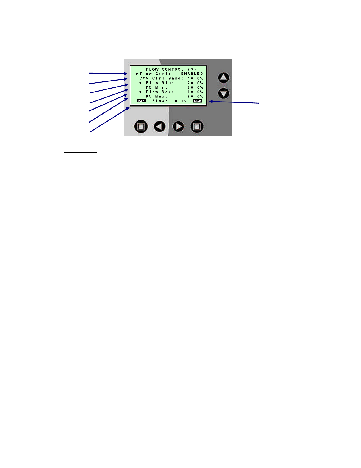
output. The flow control is a proportional pump output control base on the process flow
rate. The proportional pump output control is set by using the four parameters; Flow
Min, Pump Output Min, Flow Max, and Pump Output Max.
u
v
w
x |
y
z
{
Definitions
u Flow Ctrl: The flow control modes are ENABLED or DISABLED. When the
flow control is ENABLED, pump output percent % will increased or decreased
automatically in response to process flow changes and SCV deviation from the
setpoint. When the flow control is DISABLED, the pump output percent will
increased or decreased automatically in response PID loop control only. By
pressing either p or q key to switch between ENABLED or DISABLED control
mode.
v
w
x
y
z
{
SCV Control Band: When flow control is ENABLED, the proportional pump
output flow control will be adjusted (up and down) by the PID loop control. SCV
control band value (percent) set up how much the pump output control will be
effected by the PID loop control. For example, the SCV control band is set to
5% and the proportional pump output flow control is at 55%, the PID loop control
can adjust the pump output control up to 60% maximum and down to 50%
minimum. The SCV control band percent (%) value can be increased or
decreased by pressing the p or q key. The SCV control band percent (%)
value can be changed from 0 to 100% at 0.1% increment.
Flow Min: Minimum process flow in percent set for the produce the minimum
pump control output for the parameter below (Pump Output Min). The percent
(%) value can be increased or decreased by pressing the p or q key. The
percent (%) value can be changed from 0 to 100% at 0.1% increment.
Pump Output Min: Pump control output for the minimum process flow set
above (Flow Min). The percent (%) value can be increased or decreased by
pressing the p or q key. The percent (%) value can be changed from 0 to
100% at 0.1% increment.
Flow Max: Maximum process flow in percent set to produce the maximum
pump control output for the parameter below (Pump Output Max). The percent
(%) value can be increased or decreased by pressing the p or q key. The
percent (%) value can be changed from 0 to 100% at 0.1% increment.
Pump Output Max: Pump control output for the maximum process flow set
above (Flow Max). The percent (%) value can be increased or decreased by
pressing the p or q key. The percent (%) value can be changed from 0 to
100% at 0.1% increment.
MAIN Function Key: Pressing this key will ignore any setting modifications on
this screen and brings up the MAIN screen.
Chemtrac Systems, Inc.
Page 30
Page 32

|
SAVE Function Key: Pressing this key will save current setting modifications
and brings up the MAIN screen.
3.3.7 SCC3500XRD Flush Control Menu
From the MAIN screen, press FLUSH function key, the FLUSH CTRL MENU screen will
display. The goal of the sensor flush is to minimize the need for operator involvement
for maintenance purposes. This feature greatly enhances the reliable operation of the
Streaming Current Monitor. Within the FLUSH CTRL MENU screen, the flush
parameter settings can be modified.
Sensor Flush is only available with the optional Sensor Maintenance Module or the
Dura-Trac Flush feature.
u
v
w
x }
y
z
{ |
Definitions
u
v
w
Auto Flush: The SMM or Dura-Trac with Flush runs an automatic
flushing/cleaning sequence and will continue to flush according to the flush
parameter settings. The Auto Flush can be set to ENABLED or DISABLED.
When it is in ENABLED mode, the Monitor/Controller will begin flushing
based on Flush time value setting. When it is in DISABLED mode, the
flushing will be de-activated.
Flush Time: The flush time period setting determines how often the flushing
will take place when the Auto Flush is set to ENABLED. There are two
parameters on this menu line that can be modified; number (1 to 99 at 1 unit
increment) and number’s unit (DAY, HRS, or MIN). To modify the first
parameter setting (number), press the u key to gain access to the parameter
and then press the p or q key to scroll through the parameter range. To
modify the next parameter setting (number’s unit), press the u key to gain
access to the parameter and then press the p or q key to scroll through the
parameter range. When finish, press the t twice to get to the next menu
line.
Flush Period: The flush period setting determines the duration of water
flush to the sensor. With each flushing sequence, there are actually two
flushes performed. One at the beginning of the flush cycle (before the wash)
and one after the wash. The Flush setting determines the duration of each of
these flushes. So that, if Flush is set for 30 sec., the actual total time of flush
duration will be 60 seconds (30 seconds for each flush). The value can be
increased or decreased by pressing the p or q key. The value can be
changed from 1 to 99 at 1 second increment.
Chemtrac Systems, Inc.
Page 31
Page 33

x
y
z
{
|
}
Figure 11 shows the timing diagram of the Sensor Flush.
Chemical Period: The Chemical period setting determines the duration of
the chemical pump on time. It is recommended to use default value of 8
seconds. Excessively long chemical period (or too highly of a concentrated
chemical like Acid) can damage the probe. The value can be increased or
decreased by pressing the p or q key. The value can be changed from 1
to 20 at 1second increment.
Wash Period: The Wash period setting is only applicable for the SMM. For
the Dura-Trac with flush option, this setting should be left at 30 sec. The
Wash Period setting determines the duration of the sensor’s chemical
washing. Harder to remove scale or deposits will require longer Wash times.
It is recommended to only use a Wash duration that is no longer than
required to remove scale/deposits. Excessively long Wash durations (or too
highly of a concentrated chemical like Acid) can damage the probe. The
value can be increased or decreased by pressing the p or q key. The value
can be changed from 1 to 99 at 1second increment.
Hold Period: The Hold period setting determines how long the monitor’s
output will be held stable (or frozen at last output value before the flush) after
the flushing is finished. Flushing will cause the actual monitor reading to
fluctuate, thus it would adversely affect an automatic chemical feed control
program running through a Supervisory Control and Data Acquisition
(SCADA) or Distributed Control Systems (DCS). For this reason, the Hold
feature has been provided and must be properly set to avoid the flushing
sequence from interfering with Automatic Chemical feed control. The Output
of the monitor is automatically held stable during the flush, however, the
operator must determine the Hold duration after the flush is finished. To
determine the proper Hold setting, record the streaming current value before
the flush starts and then time how long it takes for the monitor to reach the
previously recorded reading after the flush is completed (this must be done
while the monitor is online with treated water passing through the sensor).
The simplest way of doing this will be to record the reading and then change
the Man. Flush from “Off” to “On” as this will activate the flush sequence. If it
takes 30 seconds for the reading to stabilize to the previously recorded
reading, then set the Hold setting for 1 minute. If it takes 50 seconds, then it
is recommended to set the Hold for 2 minutes. The value can be increased
or decreased by pressing the p or q key. The value can be changed from 1
to 99 at 1 minute increment.
MAIN Function Key: Pressing this key will ignore any setting modifications
on this screen and brings up the MAIN screen.
FLUSH Function Key: Pressing this key will activate a one-time manual
flush. This can be done at anytime regardless of the Auto Flush mode.
SAVE Function Key – Pressing this key will save current setting
modifications and brings up the MAIN screen.
Chemtrac Systems, Inc.
Page 32
Page 34

PUMP OUTPUT HOLD
SAMPLE ISOLATION
SENSOR FLUSH
AND RINSE
CHEMICAL PUMP
ON
OFF
ON
OFF
ON
OFF
ON
OFF
HOLD PERIOD
RINSEFLUSH
WASH PERIOD
TIME (SECONDS)
FIGURE 11. Automatic Flush Timing Diagram
NOTES
R Sample Isolation and Chemical Wash is only available with the optional SMM.
The Dura-Trac with flush option does not include the sample isolation or chemical
pump feature; however, there will still be a delay between sensor flush and rinse.
3.4 SYSTEM OPERATION
After sample flow is established and power has been applied to the sensor and
streaming current monitor, allow 10-15 minutes or longer for the reading to stabilize.
Stable conditions differ from plant to plant. The reading may fluctuate 10 to 20 units,
even under stable conditions due to the chemical not being thoroughly mixed. If
readings fluctuate widely, refer to Troubleshooting Guide. The monitor’s reading may
be negative, zero, or positive. The monitor is simply indicating the streaming current
value of the sample. In most applications, the reading will be slightly negative (anionic).
After the reading has had ample time to stabilize, adjust the chemical dosage in normal
increments to test the response of the monitor. For model SCC3500XRD, enter the
Control menu to manually adjust chemical feed. For each dosage change, the reading
should respond by changing 20 to 50 SCV units. If the response is less than 20 units,
increase the gain. Likewise, if the response is greater than 50 units, it is recommended
to decrease the gain (especially if the monitor is to be used for automatic chemical feed
control).
Next, a test should be performed to determine the Raw SCV reading. This will help
determine the LO SCV Alarm setting and give a better understanding of instrument
response. To determine the Raw SCV reading, shut off sample flow to the sensor and
turn the outlet fitting up. Pour a sample of raw untreated water into the sensor and allow
the reading to stabilize and then record the reading. This reading should serve as an
absolute alarm value, which if measured by the monitor will indicate a loss of chemical
feed. It is recommended to set the Lo SCV Alarm value (see Alarm setup menu)
between the Raw SCV measurement and the setpoint value. Further testing will help to
Chemtrac Systems, Inc.
Page 33
Page 35

determine the best ideal alarm value. The HI Alarm value should be set above the
setpoint value and at a point where testing shows an unacceptable amount of overfeed.
After verifying proper response, the next step should be to optimize the process to
establish a SCV setpoint. The SCV setpoint can then be zero’d, or offset, so that the
setpoint will be adjusted to a reading of zero (0). This is done by entering the Setup
menu and changing the Offset mode to “IN”. Offsetting the SCV is not necessary for
normal monitor operation as it is only provided so that an easier reference of zero can
be used for monitoring changes in the process. For example, if the true SCV setpoint
reading was –150, and the user offset that reading to equal zero (0), if chemical dosage
was decreased the reading may go from 0 to –50. If the reading had not been zero’d,
then the true SCV would have gone from –150 to –200 (a –50 unit change). Once the
setpoint has been zero’d, it is easier to determine whether chemical is being under or
overdosed since going negative (anionic) from 0 would be an under-dose and going
positive (cationic) would be an overdose. A setpoint of zero (0) is also easier for
multiple operators (night and day shift) to remember. Since the setpoint will change
seasonally, adjusting the setpoint so that it equals zero (0) helps to avoid confusion.
A common mistake made with the monitor’s offset function is that it has been used to rezero the reading as it drifts from the previously offset reading of zero. Once the process
has been optimized and the Streaming Current Value has been zero’d at that point, it is
no longer necessary or correct to re-zero the reading. If the reading changes from the
setpoint of zero (or the true SCV setpoint if the offset is out), the chemical dosage
should be adjusted to bring the reading back to the setpoint and not the offset function.
Eventually, a new setpoint might need to be established due to seasonal changes or
large excursions in turbidity, but under normal conditions, the setpoint should not be
changed on a daily or even weekly basis. It is recommended to use the monitor for a
few weeks in the Offset Out mode to become familiar with the operation and response
of the unit.
3.5 TREATMENT OPTIMIZATION PROCEDURE
The treatment optimization process should be done slowly and stepwise. Assuming that
the plant is producing acceptable water with present chemical dosages, trim
approximately 10%, wait for the reading to stabilize, and record the reading as the
setpoint. You may need to change GAIN setting to increase magnitude of response. If
the settled and finished water quality is still acceptable at the reduced dosages, trim
another increment, wait for the reading to stabilize, and record the reading as the new
setpoint. Continue this process, being sure to wait long enough each time to see the full
effect of the chemical feed changes on the process (i.e. settled water turbidity,
appearance of floc). In between these dosage changes it will be necessary to maintain
the setpoint. Failure to maintain the setpoint while trying to reach a lower dosage level
could result in under dosing the chemical if turbidity starts to increase. By maintaining
the setpoint, the chemical dosage is kept in check with process changes (i.e. turbidity,
flow rates).
If the Offset function is being used, re-zero the monitor reading as described in section
3.3 after each reduction in chemical feed. If a cationic coagulant is being used, the
streaming current value will become more negative with each reduction in dosage. The
"optimum setpoint" is obtained when a minimum dosage of coagulant is being fed and
produces desired results for the particular treatment process. This setpoint will remain
very close to the same reading even when raw water turbidities increase or decrease.
Simply adjust the coagulant dosage to maintain this setpoint reading on the monitor.
Chemtrac Systems, Inc.
Page 34
Page 36

This procedure may need to be repeated on a monthly to seasonal basis to ensure the
setpoint remains representative of optimum process performance.
NOTE - If automatic control is used, refer to Section 3.7 on Automatic Control.
3.6 MANUAL CONTROL USING CONTROLLER
Only available on model SCC3500XRD.
Make electrical connections between Streaming Current Controller and the chemical
feed pump. The AUTO or Manual control mode is indicated on the MAIN screen. To
switch between AUTO or Manual control mode can be done by pressing both p and q
keys from the MAIN screen. Once in Manual control mode, the pump control output
percentage can be increased or decreased by pressing the p or q key.
The AUTO or Manual control mode can also be change from the Pump Control (1)
menu. Once Pump Control (1) menu is display, move the text cursor on the far left hand
side of the screen (}) to “Pump Ctrl:” then press u the control text will blink. The
control mode can be set by pressing the pressing p or q key, this will toggle between
AUTO and MAN mode. Set the controller to MAN. Once completed, press t key then
press p or q key to get to next parameters on that screen. Next press q key to “Man
Output:” then press u the control number will blink. The percent (%) number will blink,
the manual chemical feed control value output can now be increased or decreased the
by pressing p or q key to the desire manual control value. When completed, press t
key to get to other parameters on that screen. The SAVE Function Key must be
pressed to save current setting modifications and brings up the MAIN screen.
3.7 AUTOMATIC CONTROL
Only available on model SCC3500XRD.
Automatically controlling the treatment process with the Streaming Current Controller
(SCC3500XRD) is a very simple operation, once you know how the controller works.
Most controller manuals do not explain, in simple terms, the purpose of so-called "tuning
constants" termed Proportional Band, Integral Time, and Rate. Controllers with these
three functions are sometimes called "3-mode controllers," or "PID controllers". In
order to explain the purpose of these functions, a brief review of how a simple
proportional controller works may be helpful.
Many water treatment plants have "flow controlled" coagulant feed, i.e., when raw water
flow increases, a signal is sent to the coagulant pump that immediately increases the
feed rate. In other words, there is no "lag time" between water flow increasing and
coagulant increasing. This controller works extremely well in maintaining proper dosage
as long as the water flow is the only thing changing. However, if turbidity is changing,
the proper chemical dosage cannot be maintained with a simple proportional controller.
Since the SCV is taking its sample downstream of the coagulant feed point, there will be
some "lag time" before it can sense a change in turbidity, alum feed, raw water flow, etc.
If, for instance, the SCV reading should start going more negative due to an increase in
turbidity, it will cause the controller to increase coagulant feed. This will cause the
streaming current reading to go more positive, which will cause the pump to decrease
coagulant. The result is continuous cycling above and below the setpoint, thus, the
Chemtrac Systems, Inc.
Page 35
Page 37

need for a controller with PID "tuning constants". The Proportional Band, Integral Time,
and PID Rate functions provide a way to eliminate cycling due to the lag time between
coagulant additions and streaming current sensing.
The following are description of parameters used in the PID control loop algorithm:
q Process Variable: The controlled process, meaning the value at the Controller
used to look at the process input (SCV).
q Setpoint: The target for the process variable, meaning the value at the setpoint
input.
q PID Output: The correction signal produced by the PID loop algorithm. The
output is used to control the process that effect the process variable.
q Proportional Band: The value of the property proportional constant (KP).
KP = Output range / effected process range.
q Integral Time: The value of the Integral constant (KI) expressed in repeats per
minute.
KI = Component of the loop output reacts to the amount setpoint error.
q PID Rate: The value is a function design to improve the PID loop response.
q Maximum Output: The maximum value produced by the PID loop output.
q Minimum Output: The minimum value produced by the PID loop output.
The Controller’s PID loop is designed for reverse acting; process variable goes down will
cause the output to go up. To set the loop to be direct acting, the minimum and
maximum values need to be swapped; set minimum at maximum value and set
maximum at minimum value.
The following describe each PID parameter in detail.
Proportional Band
The proportional band constant setting is dependent upon the response of the controller
or and also, to some degree, the lag time. The more responsive the Controller, and/or
the longer the lag time, the higher the proportional band constant should be set. Only
through trial and error can any tuning constant be correctly established. To test
proportional band constant setting, 10 to 30% changes in raw water flow rates can be
made. Take note of the Controller’s response as the SCV changes.
q If the response of the pump output seems to be large for the amount of SCV
change you are seeing, increase the proportional band constant setting and retest.
q If the Controller is making too small of an adjustment for the SCV change you are
seeing, the proportional band constant is set too high and should be reduced and
then re-tested.
The important thing to remember about the proportional portion of PID is that
proportional only changes the Pump Output as the SCV is changing. Or in other words,
it responds to the change in deviation as it occurs between the actual SCV and the
setpoint and does not respond to a deviation if it is not changing. So, if you notice that
as the SCV goes from a reading of 0 (setpoint) to –10 that the pump output went from
50% to 60%, and you know from experience that a 10% change in Pump output
produces a 20 unit change in the SCV, then you can assume that the proportional band
constant is set too low and needs to be increased. In the above example, you would
know that if the SCV went from 0 to –10 that the pump output would need to increase
approximately 5% (since 10% produced a 20 unit change) and you would adjust the
Chemtrac Systems, Inc.
Page 36
Page 38

proportional band constant so that the max change in PUMP Output as the reading is
changing would be 3 to 5%. We say 3 to 5% and not just 5% because you have to
consider the lag time and the Integral Time setting and its effect upon the pump output.
Integral Time
A basic rule for setting the Integral Time constant setting is that the longer the lag time,
the higher integral time constant should be. Unlike Proportional Band which actually
responds to the changes in the SCV deviation, Integral Time only responds to the time
the deviation last and will continue to correct the pump output for as long as the SCV
stays away from the setpoint value (even if the deviation is not changing). A good
example of this would be to place the controller into manual while the SCV is at the
setpoint value and then decrease the Pump Output by 10%. Once the reading has
completely stabilized at a more negative value, place the controller into Automatic mode.
Since the reading will be stable at first, but away from the setpoint, the amount of Pump
Output change you note on the display is being controlled by the Integral Time constant
setting. Proportional Band will have no effect on the Pump Output until the SCV starts
to change as a result of the higher dosage of chemical finally reaching the sensor.
During the time when the SCV is stable (but not at the setpoint), you can note how much
the Pump Output is changing and if it appears to be making too small or too large of an
adjustment, simply change the Integral Time constant setting accordingly.
PID Rate
The PID Rate function serves to improve the controllers response when higher
Proportional Band and Integral Time settings appear to still be too responsive for the
application. The PID Rate setting is usually left at 1 for most applications since
proper setting of P Gain and Integral Time are capable of providing proper response.
Higher PID F settings will serve to buffer the responsiveness of the Controller. The PID
Rate setting should not exceed 10.
R There will normally be a small amount of cycling for a few minutes after a process
change, even if Proportional Band, Integral Time, and PID Rate are set correctly.
Output Limits (Min and Max)
The output limits define the maximum and minimum values of the pump control output
signal. This control can be used to limit the % output of the controller, high or low. On a
4-20 mA controller with Max: 50%, the Output would never be greater than 12 mA, i.e.,
the chemical pump could not go above 50% output. This function can be used as a
safety measure to prevent overfeed or underfeed.
3.8 AUTOMATIC CONTROL SETUP
The controller can be programmed while it is operating in the AUTOMATIC mode.
When the controller is in the SET-UP mode, displays can be altered to review and adjust
the tuning constants. Control action continues undisturbed, except for the normal
consequences of changing a certain parameter.
The AUTO or Manual control mode is indicated on the MAIN screen. To switch between
AUTO or Manual control mode can be done by pressing both p and q keys from the
MAIN screen. When in AUTO control mode, the pump output percent will increase or
decrease automatically in response to deviations from the setpoint.
NOTE
Chemtrac Systems, Inc.
Page 37
Page 39

The AUTO or Manual control mode can also be changed from the Pump Control (1)
menu. When Pump Control (1) menu is displayed, move the text cursor on the far left
hand side of the screen (}) to “Pump Ctrl:” then press u key, the control text will blink.
The controller mode can be set by pressing p or q key, this will toggle between AUTO
and MAN modes. Set the controller to AUTO. When completed the change, press the
t key then press p or q key to get to other parameters on that screen. The
Proportional Band, Integral Time, and PID Rate can be changed by following the same
procedures. The SAVE Function Key must be pressed save current setting
modifications and brings up the MAIN screen. The MAIN Function Key can be used to
discard any new modification made to this screen and brings up the MAIN screen.
To adjust tuning constants (refer to section 3.2):
Follow these three guidelines when establishing correct tuning constants:
1. Change only one control action at a time. Making two or more corrections is
confusing and can cause the controller to get out of control.
2. Never make a large change in a tuning constant. Make a small change and
observe the effect it has on the control action.
3. Allow plenty of time for the process to stabilize before making another change,
making changes in an unstable process can be misleading.
3.9 FLOW CONTROL
Flow control is a feature that allows the Controller to perform coagulant pump control in
the process that is varying their process flow. During large process flow variation, the
PID control alone may not be able to response to the flow changes. The Controller
monitors the process flow and uses it in the flow control calculation. The Controller is
equipped with auxiliary analog input (4-20mA). When the flow control is enabled, the
pump control output is proportionally changed by the amount of process flow changes in
conjunction with the PID loop based on the SCV setpoint. The following are parameters
used in the flow control:
q Flow Ctrl: The flow control modes are ENABLED or DISABLED. When the flow
control is ENABLED, pump output percent % will increase or decrease
automatically in response to process flow changes and SCV deviation from the
setpoint. When the flow control is DISABLED, the pump output percent will
increase or decrease automatically in response PID Loop control only.
q SCV Control Band: Percent band around the flow control proportional pump
output, based on the four parameters below, that the PID loop can effect.
q Flow Min: Minimum process flow in percent set for the produce the minimum
pump control output for the parameter below (Pump Output Min).
q Pump Output Min: Pump control output for the minimum process flow set above
(Flow Min).
q Flow Max: Maximum process flow in percent set for the produce the maximum
pump control output for the parameter below (Pump Output Max).
q Pump Output Max: Pump control output for the maximum process flow set
above (Flow Max).
Chemtrac Systems, Inc.
Page 38
Page 40

3.10 TUNING CONSTANT SPECIFICATIONS
Tuning constants are stored digitally in non-volatile memory and can be changed by
front panel keys. Table below shows default PID Parameters preset by Chemtrac®.
PID Tuning Parameters Default Setting
Proportional Band 150
Integral Time 60
PID Rate 1
Experience has shown these values to be a good starting point for most applications.
However, significant changes may be necessary to tune the controller to your specific
operation.
Chemtrac Systems, Inc.
Page 39
Page 41

This page intentionally left blank
Chemtrac Systems, Inc.
Page 40
Page 42

SECTION 4.0 GENERAL GUIDELINES
4.1 STREAMING CURRENT VALUE RESPONSE FACTORS
Upscale Excursions: (Streaming Current Value (SCV), goes more positive)
Caused by:
R Decrease in pH
R Decrease in raw H20 flow
R Decrease in color
R Decrease in raw water turbidity
R Decrease in lime
R Decrease in caustic
R Decrease in anionic polymers Increase in aluminum sulfate, or PAC
R Increase in cationic polymers Increase in chlorine
Downscale Excursions: (Streaming Current Value (SCV) goes more negative)
Caused by:
R Increase in pH
R Increase in H20 flow
R Increase in color
R Increase in raw water turbidity
R Increase in lime
R Increase in caustic
R Increase in anionic polymers
R Decrease in aluminum sulfate, or PAC
R Decrease in cationic polymers
R Decrease in chlorine
Assumes that this is only parameter changing at the time.
NOTES
R Potassium Permanganate usually has no appreciable effect on the SCV (at
normal dosages of 1-2ppm).
R Increasing conductivity will drive the SCV toward zero.
R Change in lag time may affect the SCV.
Chemtrac Systems, Inc.
Page 41
Page 43

4.2 FUNDAMENTAL STREAMING CURRENT KNOWLEDGE
Introduction
It will take several weeks or maybe even a few months for an operator who has
come to rely on Jar test, eye-balling, turbidity readings, or any other method for
determining coagulant dosage to become comfortable using the monitor as a
tool for controlling coagulant feed. Very few plants install an monitor and start
controlling in Automatic mode in the first few weeks. Monitoring the response
and repeatability of the monitor through several different turbidity excursions,
and comparing process results obtained by controlling dosage to maintain a
streaming current setpoint against the results of previous methods used to
determine dosage changes is the only way to prove the reliability of the
instrument and gain the confidence needed to realize the full potential of the
technology. The operator will soon realize that the time consuming jar testing
procedure is no longer where his comfort lies. The information provided by the
monitor is equivalent to a 5 second jar test once the operator understands how
to interpret the reading.
The Importance Of Trending And Manual Control
It is suggested to hook up a chart recorder, or connect the monitor to SCADA, so
that the response and trend of the monitor can be monitored and compared to
turbidity readings, flow rates, and coagulant dosage adjustments. The
information derived from comparing the streaming current value to these other
parameters will assist the operator in understanding how the monitor responds to
changing conditions. During the first few weeks of operation, the monitor should
be used in Manual mode and all the operators should become familiar with how
to interpret the monitor reading. If the reading moves in the negative direction
from the setpoint as a result of an increase in turbidity, the operator should
manually increase the dosage to re-establish the setpoint and feel free to run a
Jar test to compare the results with. Following this procedure and closely
reviewing the monitor trends and responses will speed up the process of the
operators becoming comfortable with using the monitor to determine or
automatically control the coagulant dosage.
Setpoint – Why Does It Change?
It is important for the operator to understand that the ideal monitor setpoint can
occasionally change due to changes in water chemistry and wear on the probe
and piston assemblies. For example, a WTP may find that under the exact same
turbidity conditions a setpoint of 150 works great in the summer, but that a
setpoint of 50 works best in the fall. Unfortunately, there is no calibration
technique that can be used to correct for the monitor’s response to seasonal,
chemistry changes. This is the reason the monitor is considered a relative
reading. The dominating cause for the setpoint changing is due to seasonal
water chemistry changes (e.g. changes in PH or Color / Organics). Seasonal
additions of chemicals such as Potassium Permanganate or Powder Activated
Carbon can also have an effect on the monitor’s setpoint. Extreme changes in
turbidity can result in a significant enough change in chemistry that it may effects
the setpoint. Because the monitor’s setpoint can change, occasional
verifications of the setpoint need to be made. If Jar testing or operator
experience show that the setpoint currently being used may no longer be ideal,
simply readjust the chemical feed manually to re-optimize the process and
establish the new stabilized reading as the new ideal setpoint. These
Chemtrac Systems, Inc.
Page 42
Page 44

verifications of the setpoint do not need to be performed daily, or even weekly,
unless there is a large, sudden change in turbidity or if a chemical that was not
being fed previously is going to be introduced (i.e. Potassium Permanganate).
Verifying the setpoint once every few weeks should be adequate for most
applications.
Maintenance Issues
To keep the monitor working properly, occasional maintenance will be
necessary. Cleaning only takes a few minutes to perform and is usually needed
once every 2 to 6 weeks (depending upon water quality conditions). An easy
test to see if the sensor needs to be cleaned is to first verify the reading has not
become “noisy” or “bouncy” and then make small changes in chemical feed to
make sure the sensor has not become unresponsive. As long as the monitor is
stable, responsive, and the response is no less than it has been noted in
previous response testing, the sensor does not need to be cleaned. If the
reading does appear to be less responsive or noisy, then record the amount of
response or noise (signal drift as measured in a one minute period) and then
remove the probe and piston for cleaning. First look to see if there is any
obvious buildup or solids in the probe or on the piston. Then, clean the probe
with a suitable cleaner (such as Comet/Ajax or Rover/CLR). Finally, rinse the
parts and install them back into the sensor. After allowing the sensor time to
stabilize, compare response and noise (if any) to previous results to verify the
cleaning did indeed improve response. If not, the piston and/or probe may need
to be replaced.
Eventually the moving parts of the monitor will wear. Most notably, the probe
and piston will wear the fastest and require replacement once every two years on
average. Once again, to determine if the probe and piston need to be replaced
simply make small chemical feed adjustments. If the probe is unresponsive and
cleaning does not improve the result, the probe and piston most likely need to be
replaced. Having a new set on hand to compare against is the best method of
determining if the parts need to be replaced. The motor in the monitor sensor
will also need replacing after 3 to 5 years of use. If the reading starts to become
slightly unstable, and cleaning or replacing the probe and piston does not
eliminate the unstable reading, check the shaft of the motor to see if it has
excessive movement. If so, replace the motor.
The Usefulness Of Spare Parts For Determining Probe/Piston Wear
If a spare probe and piston are on hand, it is suggested to keep these put aside
for comparing with the set in use and for replacing the old set when they become
worn. If the spare set is routinely swapped with the other set, then both sets will
experience wear. Always having a new, unused set on hand ensures you have a
point of reference for determining when your old set absolutely needs to be
replaced. For example, to compare the readings of your old probe and piston to
a new set, simple close the sample valve and drain all the sample out of the
probe block by removing the probe (you will also probably want to clean the
probe and piston at this time). Re-insert the probe and turn the outlet fitting 180
degrees so that it is pointing up. Next, pour a sample of untreated, raw water
into the probe block through the upturned outlet fitting. Allow the reading to
stabilize and record the reading and any amount of signal oscillation (bounce) as
seen in a one minute interval. Finally, remove the old probe and piston and
install the new set and pour in the raw water sample. Compare the readings of
the new probe and piston to the old set. If the readings from the old probe are
Chemtrac Systems, Inc.
Page 43
Page 45

less than 50% of what the new probe reads and/or noticeably less stable, it is
recommended to replace the old set unless the operator feels confident that the
old set was performing satisfactorily. Once the signal strength from a probe and
piston set has degraded down to 50% to 25% of what a new set’s signal strength
is, the parts should be considered worn and probably in need of replacing.
It may not be necessary to replace both the piston and the probe at the same
time as usually the piston wears faster than the probe. To check this, simply
install a new piston with the old probe and compare those readings to the ones
obtained with the new piston and new probe combination. If the old probe and
new piston combination produce a reading that is within 50% or more of the new
set, then the probe can still be used as long as the new piston is installed. The
same procedure should be followed with a new probe and old piston to
determine if the old piston is still suitable for use. Using this procedure, the
operator can determine which part, if not both, needs to be replaced. Be sure to
order a replacement part(s) to have on hand as a spare once you have installed
the new probe and/or piston to replace the worn part(s).
Simple Functionality Test
The procedure of pouring raw water into the probe block to check the probes for
wear can also be used to check the probe’s response and/or troubleshoot the
system. Many times when there is a problem associated with the monitor, the
operator will assume the instrument is at fault. If the operator does not have an
easy method of testing the monitor’s functionality, he will most likely not look for
another cause. A simple method of checking the monitor’s performance is to
pour untreated, raw water into the probe as outlined above. First, verify that the
raw water reading is significantly different from the treated water reading. The
raw water reading should be more negative than the treated water sample by at
least 50 units (taking into consideration that the gain has been properly set and
that coagulant dosage is greater than a few ppm). The raw water reading will
also normally be greater than –100 on 1X gain (except with samples that have a
high alkalinity/conductivity). The reading on the raw water should also be stable
and not erratic or oscillating. Finally, add a small amount of coagulant to the raw
water sample and pour the sample into the sensor to verify the reading responds
by moving in the positive direction. If the unit responds as outlined above, the
unit is most likely performing within specifications. If you are unsure about your
results, or cannot find another cause for whatever problems you are having with
the monitor (e.g. lack of response, erratic reading), then contact the factory.
Chemtrac Systems, Inc.
Page 44
Page 46

SECTION 5.0 TROUBLESHOOTING GUIDES
PROBLEMS POSSIBLE CAUSE(S) CORRECTIVE ACTION
1. Display fluctuates
rapidly and widely
on treated sample.
2. Display does not
change with
change in
coagulant dosage.
A. Incomplete dispersion or
mixing of coagulant(s) in
raw water at point of
sampling.
B. Chemical feeders erratic or
partially plugged.
C. Raw water flow-turbidity
fluctuating.
D. GAIN setting too sensitive.
E. Cell bottom plug loose or
O-ring missing.
A. GAIN setting too low.
B. Wrong sample point or
insufficient mixing..
C. Sample cell dirty.
D. Excessive “lag time”
between coagulant
injection point and sensor
sample cell.
A. Check stability of readings on
raw or finished water. If stable,
incomplete mixing is the
problem. Move sampling point
further downstream, or resolve
mixing problems.
B. Fix feeders.
C. Check R/W flow controls/charts,
and turbidity.
D. Decrease GAIN setting.
E. Tighten plug. Check O-ring
(See Cleaning Procedures).
A. Increase GAIN setting.
B. Select correct sample point.
C. Clean cell (see Cleaning
Procedures).
D. Move sampling point closer to
coagulant feed point and/or
decrease sample TRANSPORT
time (See Selecting Proper
Sample Point).
3. Display indicates
0.00, or closely
thereto, and does
not change with
change in
coagulant dosage.
A. No water sample to sensor.
B. Motor not turning.
C. Dirty or inoperative probe.
D. Opt switch misaligned.
E. Opt switch inoperative.
F. Sensor output connections
incorrect.
G. Circuit card component
faulty.
A. Establish proper sample flow.
B. Turn on motor.
C. Clean or replace probe.
D. Adjust opt switch position for
maximum meter reading on
water sample and tighten
securely in place.
E. Replace opt switch.
F. Check wiring.
G. Replace circuit card.
Chemtrac Systems, Inc.
Page 45
Page 47

This page intentionally left blank
Chemtrac Systems, Inc.
Page 46
Page 48

SECTION 6.0 MAINTENANCE PROCEDURES
The Dura-Trac sensor is supplied with two (2) probes and (2) pistons so freshly cleaned parts
can always be on hand.
6.1 REPLACEMENT PROCEDURES
The following steps describe probe replacement:
1. Disconnect the lead wire from the enclosure and remove the lower retaining slip nut
from the probe.
2. Remove probe by pulling on the tab. You may need to twist slightly.
3. Remove the piston using a ¼” flatblade screwdriver.
4. Clean any debris from cell housing.
5. Screw clean piston into place. Do not over tighten. Only slight torque is necessary.
6. Insert clean probe into cell housing.
7. Slip retaining nut over probe lead wire and tighten onto probe. Finger tight is
adequate - be careful to avoid cross threading the nut.
8. Connect probe lead wire to side of enclosure.
9. It may take several minutes for monitor readings to stabilize with a new probe.
Sensitivity to process changes may also be greater. If the Offset is used, the user
must set the Offset to OUT position. After SCV reading is stabilized, set the zero
Offset to the IN position to re-zero the SCV reading.
R If monitor is being used for automatic dosage control, put the controller into
MANUAL mode before starting replacement procedure.
6.2 CLEANING PROCEDURES
Depending on the type of contamination, see table below for different cleaning
procedures recommended.
CAUTIONS
Chemtrac Systems, Inc.
Page 47
Page 49

TYPE OF CONTAMINATION CLEANING PROCEDURE
Mineral scale from alum/lime addition Comet or other Abrasive Cleaner
Deposits caused by raw water
iron/manganese, or where ferric salts or
ROVER (available from Hach Chemical)
1 spoonful per pint tap water
potassium permanganate is used for
treatment.
Organics from raw water or where
Comet or other Abrasive Cleaner
polymers are used.
Oil/Grease Comet or other Abrasive Cleaner
A “soak and brush” method is recommended for any contaminant. Soak only long
enough to dissolve/remove the material. Probe surfaces should be thoroughly washed
with clean water to remove any residual cleaning compound.
CAUTIONS
R Do not soak entire probe cartridge, only soak inside the bore. Acid concentration
shall not exceed 15% concentration.
6.3 REPLACEMENT PARTS
Figure 12 AND 13 illustrates Dura-Trac and Dura-Trac II sensor parts identification with
part numbers. Table below lists recommended replacement parts.
Part Number Description Replacement Interval
1701 Delrin Piston 1 to 2 years
8601 Probe Cartridge 1 to 3 years
1301 110VAC Drive Motor 3 to 5 years
5017 Viton Diaphragm 3 to 5 years
8702 Probe Washer If Lost
Chemtrac Systems, Inc.
Page 48
Page 50
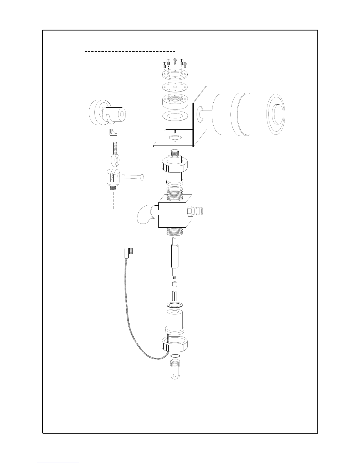
110 CRANK
ASSEMBLY
(5302)
OPTO
SWITCH
(1308)
ROD END
(3707)
6-32 SCREWS
WASHER
(1608)
VITON SEAL
(7701)
MOUNTING NUT
(1607)
NEOPRENE
WASHER
(5016)
4-40 SET
SCREW
MOTOR BRACKET
(3311)
110 MOTOR
(1301)
YOKE PIN
(5720)
YOKE
(5710)
PROBE BLOCK
GUIDE
(8711)
PISTON
(1701)
PROBE
WASHER
(7703)
PROBE
(8601)
(5622)
DURA NUT
(4200)
EXTENSION
(5611)
3/4" BARB INLET
(5021)
FIGURE 12. Dura-Trac Sensor Parts Identification
Chemtrac Systems, Inc.
DURA NUT
(4200)
O-RING
(1605)
DURA PLUG
(8606)
Page 49
Page 51
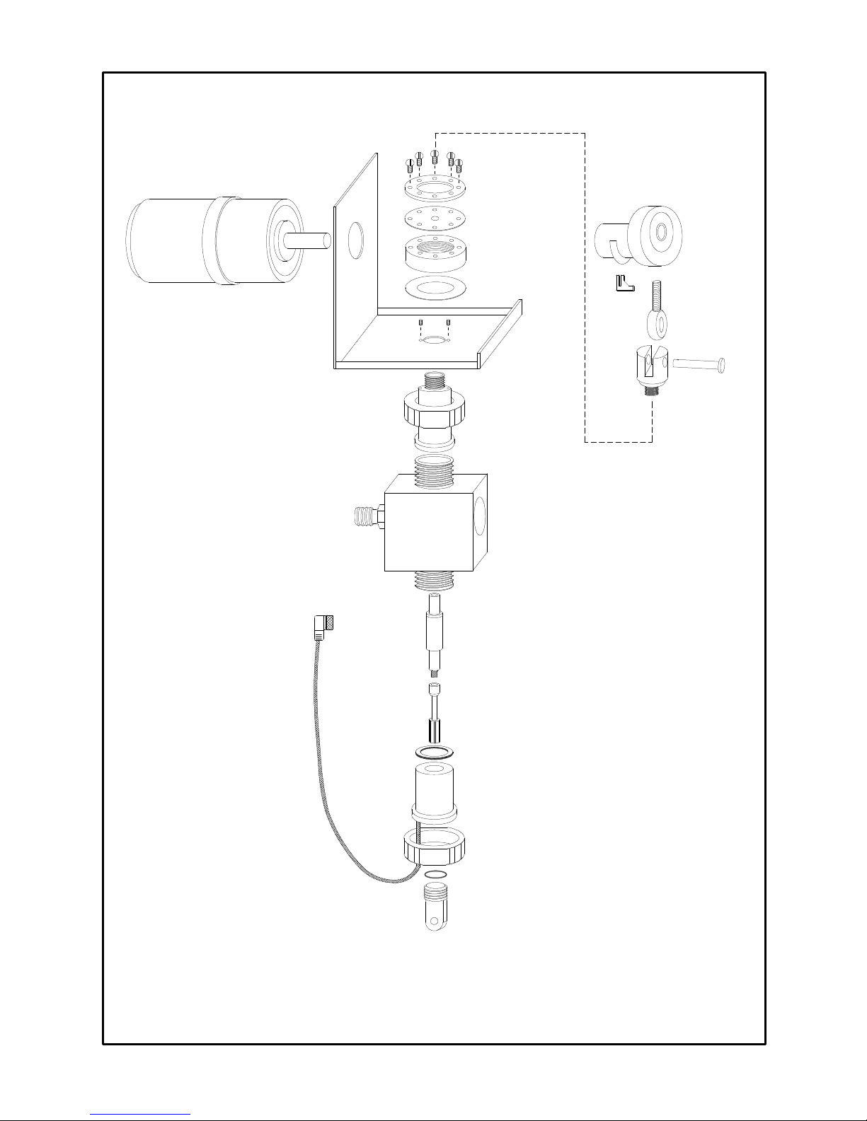
110V MOTOR
(5470)
4-40 SET
SCREWS
WW EXTENSION
6-32 SCREWS
WASHER
(1608)
DOUBLE THICK
VITON SEAL
(7702)
MOUNTING NUT
(1607)
NEOPRENE WASHER
(5016)
MOTOR
BRACKET
(3311)
DURA NUT
(4200)
(5611)
MOTOR CRANK
(3300)
OPTO
SWITCH
(1308)
ROD END
(3707)
YOKE PIN
(5720)
YOKE
(5710)
3/4" BARB INLET
(5021)
WW PROBE BLOCK
(5630)
GUIDE
(7720)
PISTON
(1710)
PROBE
WASHER
(7703)
PROBE
(8601)
DURA NUT
(4200)
O-RING
(1605)
DURA PLUG
(8606)
FIGURE 13. Dura-Trac II Sensor Parts Identification
Chemtrac Systems, Inc.
Page 50
Page 52

6.4 ORDERING INFORMATION
To place an order for spare parts you may either call, email, or fax Chemtrac® directly or
contact your local distributor or representative. The following information should be
included in your request: Model number of your monitor, part number(s), qty,
description of parts required, and purchase order number. Please contact Chemtrac®
for up to date pricing.
Parts order normally ship within 24 hours.
Chemtrac Systems, Inc
6991 Peachtree Industrial Blvd., Building 600
Norcross, GA 30092
Phone: 1-800-442-8722 (Inside US only), 770-449-6233
Fax: 770-447-0889
Email: sales@chemtrac.com
Website: www.chemtrac.com
Chemtrac Systems, Inc.
Page 51
Page 53

This page intentionally left blank
Chemtrac Systems, Inc.
Page 52
Page 54

SECTION 7.0 MECHANICAL SPECIFICATIONS
The following Figures 14 thru 19 illustrate enclosure and mounting dimensions for Streaming
Current Monitor/Controller, Dura-Trac Sensor, Dura-Trac Sensor with Flush, Dura-Trac II
Sensor, and Sensor Maintenance Module.
Power
Service
Diag.
Alarm
11.2" [285mm]
13.6" [345mm]
CHEMTRAC
SYSTEMS, INC.
9.2" [234mm]
7.7" [196mm]
SCC3500XRD
12.5" [317mm]
7.71" [196mm]
6.3" [161mm]
6.1" [155mm]
FIGURE 14. Streaming Current Monitor/Controller Dimensions
Chemtrac Systems, Inc.
Page 53
Page 55

9.2" [234mm]
7.7" [196mm]
CHEMTRAC
SYSTEMS, INC.
5.3" [135mm]
8.5" [215mm]
PATENTED MADE IN U.S.A.
FIGURE 15. Dura-Trac Sensor Dimensions
11.2" [285mm]
CHEMTRAC
SYSTEMS, INC.
9.7" [247mm]
DURA-TRAC
TM
7.2" [183mm]
14.7" [373mm]
6.3" [161mm]
9.2" [234mm]
10.5" [266mm]
PATENTED MADE IN U.S.A.
FIGURE 16. Dura-Trac II Sensor Dimensions
Chemtrac Systems, Inc.
DURA-TRAC II
TM
18.8" [477mm]
Page 54
Page 56
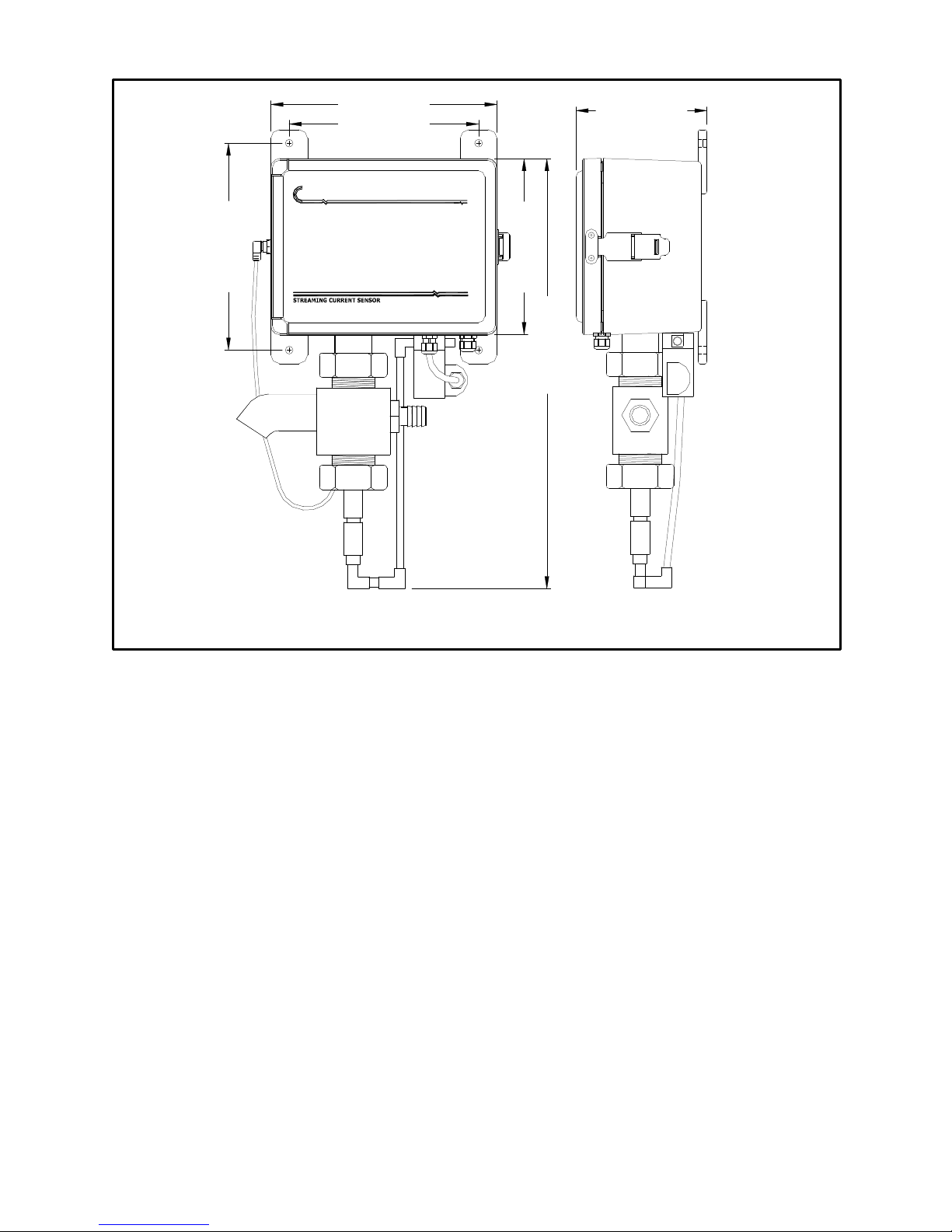
9.2" [234mm]
7.7" [196mm]
CHEMTRAC
SYSTEMS, INC.
5.3" [135mm]
8.5" [215mm]
PATENTED MADE IN U.S.A.
DURA-TRAC
TM
7.2" [183mm]
17.6" [447mm]
FIGURE 17. Dura-Trac Sensor with Flush Dimensions
Chemtrac Systems, Inc.
Page 55
Page 57

9.2" [234mm]
10.5" [266mm]
PATENTED MADE IN U.S.A.
CHEMTRAC
SYSTEMS, INC.
11.2" [285mm]
9.7" [247mm]
DURA-TRAC II
6.3" [161mm]
TM
21.8" [554mm]
FIGURE 18. Dura-Trac II Sensor with SMM Dimensions
11.2" [285mm]
6.3" [161mm]
10.5" [266mm]
9.7" [247mm]
9.2" [234mm]
FIGURE 19. SMM Dimensions
Chemtrac Systems, Inc.
Page 56
Page 58
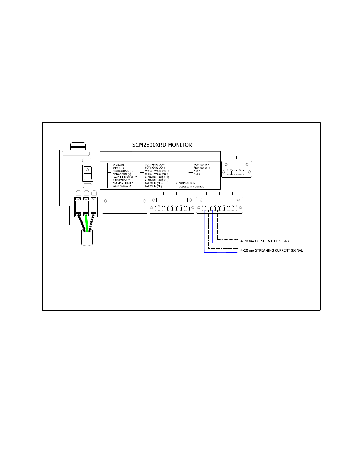
ADDENDUM
On specific model of the SCM2500XRD, the analog output (4-20mA) representing the Offset
value is provided at terminals 11 and 12; see figure below. Terminal 11 is labeled Offset Value
(AO+) and terminal 12 is labeled Offset Value (AO-). The scaling for the Offset value analog
output is from -1000 to +1000 streaming current value. The two analog outputs are provided to
allow the customer to monitor the SCV Signal and Offset value remotely. The explanation of
the Offset mode and Offset value are described in Section 3.2.2 SCM2500XRD Setup Menu
(1).
FUSE
FUSE: AGC-1.5A
OFF
L
WARNING TURN POWER OFF BEFORE MAKING ANY WIRE CONNECTIONS
TO AVOID DAMAGING THE ELECTRONIC CIRCUIT.
ON
GL N
GND
1
2
3
4
5
6
7
SMM | Sensor
8
N
9
10
11
12
13
14
15
16
1
1817 19 20
17
18
*
*
*
*
324
19
20
*
865 7
9
1110
16151413
12
Signal Wires Interconnection Diagram
Chemtrac Systems, Inc.
Page 57
 Loading...