

Page 1
S461/T
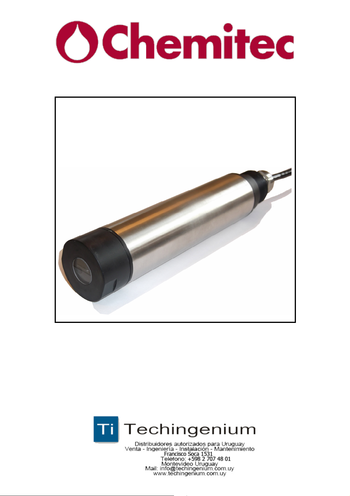
SONDA DI TORBIDITA’ A INFRAROSSI
INFRARED TURBIDITY PROBE
MANUALE TECNICO / TECHNICAL MANUAL
P/N: ………………….
Rev. 0 Ver. 1.0
EDIZIONE Febbraio 2014 / EDITION February 2014
Page 2

DDaattaa SShheeeet
SS446611TT IInnffrraarreedd TTuurrbbiiddiittyy
e
PPrroobbe
t
The S461/T probe is used for the optical measure of turbidity in pure and
process waters up to 4000 NTU.
The probe uses the 90° scattered light method.
Applications
• Measure of turbidity in wastewater
• Measure of turbidity in primary, industrial, recirculating water
Features and benefits
• Reliable concentration measurement
using optical measuring process
• Infrared light pulsing beams scattering method
• Black rigid PVC and AISI 316 sensor body
• No mechanically moving parts
• Measured value pre-processing in sensor resulting in
low signal transmission sensitivity
• Immediate installation and easy manteinance
Turbidity measurement with the 90° scattered light method
By turbidity we mean the scattered component of a light beam which is
diverted away from its original course by optically denser particles in the
medium e.g. solid matter particles.
Measurements are made using the standardised 90° scattered light method in
accordance with ISO 7027 / EN 27027. The measuring method is based on
the Tyndall effect.
The turbidity of the medium is determined from the amount of scattered light.
The transmitted infra-red light beam is scattered by the particles in the
medium.
The scattered beams are measured by scattered light receivers which are
fixed at an angle of 90 to the
transmitted light. The measured scattered light signals are converted to
frequency signals.
The frequency signals are assigned to corresponding turbidity units and solid
matter concentrations,
and appear in the display.
Principle of 90° scattered beam Measurement:
S461T Infrared Turbidity Probe – Data Sheet Page 9
Page 3

DDaattaa SShheeeet
I0 = Intensity of transmitted light
IS = Intensity of scattered light
A = Geometrical factor
C = Concentration
f(α)= Angle correlation
P = Particle
Composition of the supply
Is = I
SS446611TT IInnffrraarreedd TTuurrbbiiddiittyy
e
0
⋅⋅⋅⋅ A⋅⋅⋅⋅
C
⋅⋅⋅⋅
f(α)
PPrroobbe
t
2 1
The supply consists of a single package containing the following parts:
1. 1 S461/T Sonda Torbidità ad infrarossi con 10 metri di cavo
2. 1 Technical manual for instruction
S461T Infrared Turbidity Probe – Data Sheet Page 10
Page 4

DDaattaa SShheeeet
Installation in tank
SS446611TT IInnffrraarreedd TTuurrbbiiddiittyy
e
PPrroobbe
t
Install the probe in the tank so that it is immersed for at least 20 cm and the
distance from the walls and the bottom of the tank is not less than 20 cm.
Installation in channel
Install the probe in the channel so that it is immersed for at least 20 cm and
the distance from walls and bottom of the channel is not less than 20 cm.
S461T Infrared Turbidity Probe – Data Sheet Page 11
Page 5
DDaattaa SShheeeet
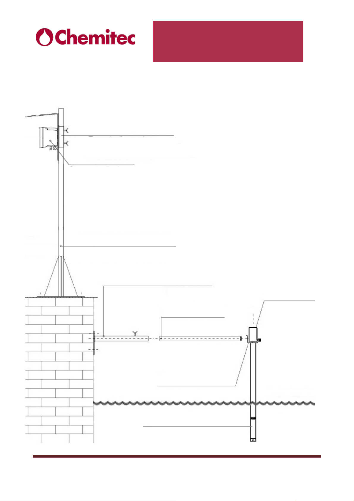
Protection top
S461T Turbidity Probe
Anchoring to poolside devices
Measuring Unit
SS446611TT IInnffrraarreedd TTuurrbbiiddiittyy
e
PPrroobbe
t
Insole pedestal h=600mm
Insole pedestal h=1700mm
Extension L=700mm
D42 Probeholder bracket
Wall bracket
D42 Probeholder
S461T Infrared Turbidity Probe – Data Sheet Page 12
Page 6
DDaattaa SShheeeet
SS446611TT IInnffrraarreedd TTuurrbbiiddiittyy
e
PPrroobbe
t
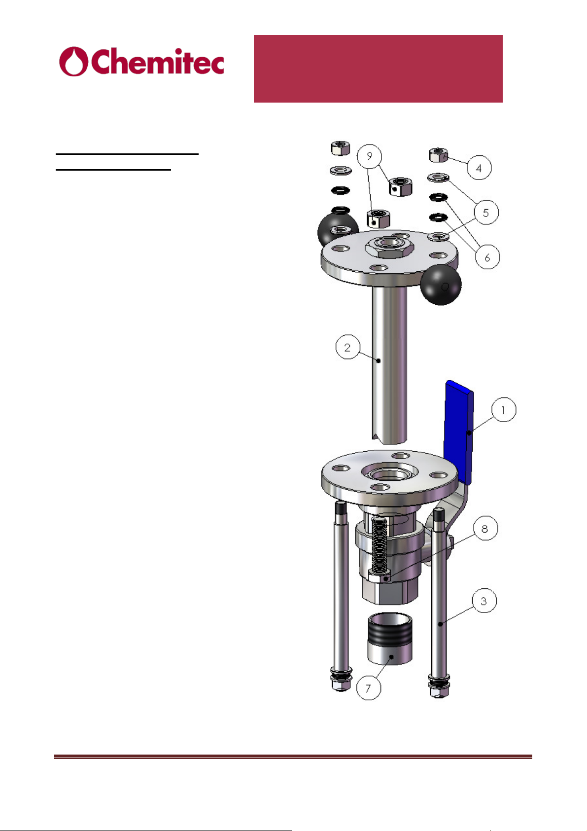
Insertion in pipeline devices
Insertion probeholder
Code 9700740060
Nomenclature of the parts included
in the delivery:
1. Valve ensemble
2. Probe ensemble
3. Stop Pole (2)
4. M12 Nut (4)
5. 12 Washer (8)
6. O-ring 4050 (8)
7. AISI 316 weld socket
8. M16x60 Bolt (2)
9. M16 Nut (2)
Instructions for a proper assembly:
Unscrew the socket (7) from the valve
ensemble (1) and weld it on the pipe.
Unscrew the two M16x60 bolts (8)
from their respective nuts (9).
Unscrew the two superior M12 nuts
(4) from the stop poles (3) and
remove the superior washers (5) and
O-rings (6).
Then inserti the probe ensemble (2)
into the valve unit (1) until aligning the
two flanges and the corresponding
holes of the two blocks.
Let the stop poles (3) pass through
the holes of the probe ensemble and
then reinsert superior washers (5)
and O-rings (6), then screw the M12
superior bolts (4) to the stop poles
(3). Repeat this procedure with the
M16x60 bolts (8), then tighten the
corresponding M16 Nuts (9).
S461T Infrared Turbidity Probe – Data Sheet Page 13
Page 7

DDaattaa SShheeeet
Necessary
SS446611TT IInnffrraarreedd TTuurrbbiiddiittyy
Precautions for installation in pipeline
S461T Probe
Revolvable
PPrroobbe
space for
disassembly
e
t
Necessary space for
Flow direction
nipple welding and
valve assembly
Attention: measures refer to the inside part of the pipe
S461T Infrared Turbidity Probe – Data Sheet Page 14
Page 8
DDaattaa SShheeeet
TEC
H
NIC
AL DATA
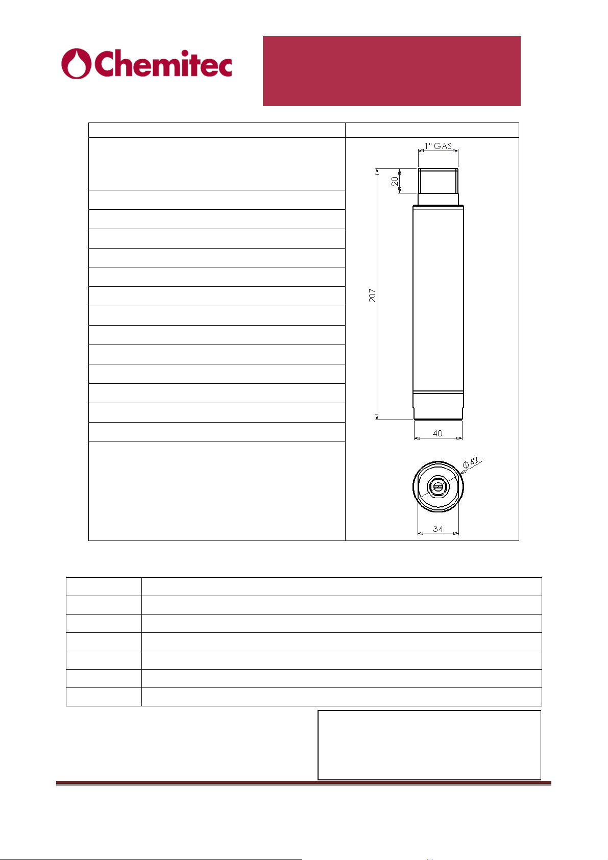
DIMENSIONS
Material
s
Thread
:
Measuring ranges
:
Measuring method
:
Accuracy
:
Ripe
atability
:
Calibra
tion
:
Max Working Pressure
:
Mechanical Protection:
Cable
:
Power Supply
:
Max Absorption:
Outputs
:
Cable colors coding
CHEMITEC s.r.l.
SS446611TT IInnffrraarreedd TTuurrbbiiddiittyy
e
PPrroobbe
t
WorkingTemperature: 0÷60 °C
:
Black PVC and AISI 316 Body
Special Glass Optics
Viton OR
1” GAS
0-4, 0-40, 0-400, 0-4000 NTU
90° Scattered light
± 2% of f.s.
98 %
by points
4 bar
IP68 Sensor+cable
10m integral
12…24Vdc
3W
RS485 ( 4-20mA optional)
Order codes
9700590063
9720590063
9730590063
9740590063
9750590063
9760590063
9770590063
RED +24Vdc
BLACK GROUND
YELLOW A+ RS485
GREEN B- RS 485
WHITE + 4-20 mA
BROWN - 4-20 mA
S461T turbidity sensor immersion style 10m cable
S461T turbidity sensor immersion style 10m cable with RS485 output
S461T/INS Turbidity sensor insertion style 10m cable with socket
S461T PVC Turbidity sensor immersion style special Oring 10m cable
S461T PVC Turbidity sensor immersion style 10m cable RS485 Output
S461T AISI316 turbidity sensor immersion style 10m cable
S461T turbidity sensor insertion style 10m cable with 4-20mA output
Via Isaac Newton 28 - 50018 Scandicci (FI)
Tel. +39 055 7576801 fax +39 055 756697
Web site: www.chemitec.it
E-mail: [email protected]
S461T Infrared Turbidity Probe – Data Sheet Page 15
 Loading...