

Page 1
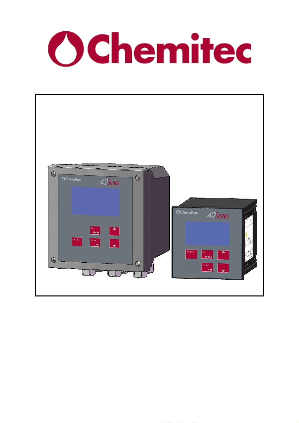
4222
CONDUCTIVITY AND TEMPERATURE
ANALYZER
TECHNICAL MANUAL
P/N:
………………….
Rev. 1 Ver. 2.2
EDITION September 2012
Page 2
CONDUCTIVITY AND TEMPERATURE ANALYZER
4222
TECHNICAL MANUAL P/N XXX-0000 Rev.1 Ver.2.2
GENERAL CLAUSES
Despite the fact that the utmost attention has been given taken in the
preparation of this document, CHEMITEC s.r.l. cannot guarantee the
accuracy of all information contained and cannot be held responsible for any
consequent mistakes or damages that may arise from its use or application.
The products, materials, software and services presented in this document
are subject to development and with regards to presentation and
performance characteristics, CHEMITEC s.r.l. reserves the right to carry out
any modifications without prior notice.
The reproduction or copy of this manual, even partial, and using any
procedure is strictly prohibited.
COPYRIGHT
AUTHORISED TECHNICAL SUPPORT CENTRES
CHEMITEC s.r.l.
Via Isaac Newton, 28 – 50018 Scandicci - FIRENZE
II
Page 3

INDEX
CONDUCTIVITY AND TEMPERATURE ANALYZER
4222
TECHNICAL MANUAL P/N XXX-0000 Rev.1 Ver.2.2
1 GENERAL ............................................................................................................................................................... 1
1.1 INFORMATION ON THE MANUAL .............................................................................................................. 1
1.1.1
CONVENTIONS ........................................................................................................................................ 1
1.2 DECLARATION OF RESPONSIBILITY BY THE MANUFACTURER ........................................................ 2
1.3 LIMITS OF USE AND PRECAUTIONS FOR SAFETY.................................................................................. 2
1.3.1
ELECTRICAL SAFETY ............................................................................................................................. 2
1.3.2
SAFETY OF THE OPERATIVE ENVIRONMENT .................................................................................... 3
1.4 GRAPHIC SYMBOLS ...................................................................................................................................... 4
1.5 CAUTION SYMBOL ........................................................................................................................................ 4
1.6 PLATE DETAILS ............................................................................................................................................. 5
1.7 INFORMATION ON RECYCLING AND USE OF MATERIALS .................................................................. 5
1.7.1
SPECIAL ATTENTION TO CRITICAL COMPONENTS .......................................................................... 5
2 GENERAL DESCRIPTION ................................................................................................................................... 6
2.1 MEASURING PRINCIPLES ............................................................................................................................ 6
2.2 MAIN CHARACTHERISTICS ......................................................................................................................... 7
2.2.1
TECHNICAL CHARACTERISTICS FOR CONDUCTIVITY (PRIMARY MEASURE) ............................. 8
2.2.2
TECHNICAL CHARACTERISTICS FOR MEASURING OF SECONDARY TEMPERATURE ................ 8
2.2.3
OPERATING FEATURES ......................................................................................................................... 8
2.3 CONTROLS, INDICATORS AND CONNECTIONS .................................................................................... 10
2.4 GRAPHIC DISPLAY ...................................................................................................................................... 11
2.4.1
LIST OF PRIMARY MENUS ................................................................................................................... 11
2.4.2
DIVISION OF THE GRAPHICAL DISPLAY INTO AREAS IN THE RUN METHOD ........................... 12
3 INSTALLATION ................................................................................................................................................... 15
3.1 COMPOSITION OF THE SUPPLY ................................................................................................................ 15
3.1.1
INSTALLATION OF WALL MOUNTED DEVICE .................................................................................. 15
3.1.2
INSTALLATION OF 96x96 ELECTRICAL PANEL DEVICE ................................................................. 16
3.1.3
INSTALLATION OF 144x144 ELECTRICAL PANEL DEVICE ............................................................. 17
3.1.4
CONNECTIONS TO THE POWER SUPPLY .......................................................................................... 17
3.1.4.1 Electrical Connections to the dosage systems (Users) ........................................................................ 18
3.1.4.1.1
3.1.4.1.2
3.1.4.2 Connections to the Power Supply ........................................................................................................ 21
3.1.5
4 METHODS OF USE ............................................................................................................................................. 22
4.1 COMPOSITION OF THE MEASURING SYSTEM ...................................................................................... 22
4.1.1
4.1.2
4.2 START UP OF THE SYSTEM ....................................................................................................................... 23
4.2.1
4.2.1.1 Contrast adjustment ............................................................................................................................. 23
4.3 INTRODUCTION OF OPERATIVE PARAMETERS – THE USE OF KEYS .............................................. 23
4.3.1
4.3.2
4.3.3
4.3.4
4.3.5
4.3.6
4.3.7
4.3.8
Connection terminal box for wall mounted 4222 ......................................................................... 19
Connection terminal box for panel mounted 4222 ........................................................................ 20
CONDUCTIVITY PROBE CONNECTION ............................................................................................. 21
MINIMUM CONFIGURATION .............................................................................................................. 22
MAXIMUM CONFIGURATION ............................................................................................................. 22
MENU FUNCTIONS AT START ............................................................................................................. 23
SETUP MENU (TEMPERATURE – SYSTEM SETUP) .......................................................................... 24
SETUP MENU (DIGITAL INPUT – SELECT MEASURE) ..................................................................... 26
SETUP MENU (SETUP MEASURE) ...................................................................................................... 26
OUTPUTS MENU (RELAY OUTPUTS – SET POINT 1) ....................................................................... 28
OUTPUTS MENU (RELAY OUTPUTS – SET POINT 2, ETC.) ............................................................. 31
OUTPUTS MENU (SET POINT TEMP.) ................................................................................................ 33
OUTPUTS MENU (CURRENT OUTPUT) .............................................................................................. 34
OUTPUTS MENU (SETUP PID) ............................................................................................................ 35
III
Page 4

CONDUCTIVITY AND TEMPERATURE ANALYZER
TECHNICAL MANUAL P/N XXX-0000 Rev.1 Ver.2.2
4.3.9
CALIBRATIONS MENU .......................................................................................................................... 36
4.3.9.1 Conductivity calibration ...................................................................................................................... 37
4.3.9.2 Temperature calibration ...................................................................................................................... 38
4.3.10 ARCHIVE MENU .................................................................................................................................... 39
4.3.11 MEASURING GRAPHICS MENU .......................................................................................................... 40
4.3.12 MANUAL CONTROL MENU .................................................................................................................. 41
4.3.13 FUNCTIONS IN RUN.............................................................................................................................. 42
4222
5 USER MAINTENANCE ....................................................................................................................................... 44
5.1 SPECIAL CAUTIONS FOR CRITICAL COMPONENTS ............................................................................. 44
6 MODBUS PROTOCOL ........................................................................................................................................ 45
7 WARRANTY ......................................................................................................................................................... 52
8 REQUEST FOR ASSISTANCE ........................................................................................................................... 53
8.1 PROCEDURE OF REQUEST FOR TECHNICAL ASSISTANCE ................................................................ 53
8.2 MAIN CHEMITEC OFFICES ......................................................................................................................... 53
IV
Page 5
1 GENERAL
1.1 INFORMATION ON THE MANUAL
This document contains reserved information. It may be subject to modifications and updates
without any prior notice.
Printing chronology:
First edition: 4222 – Ver. 0 Rev. 1.0
This manual is an integral part of the instrument. Upon initial installation of the equipment, the
operator must carry out a careful control of the contents of the manual in order to check its integrity
and completeness.
If for any reason it is ruined, incomplete or inadequate please contact CHEMITEC in order to
reintegrate or replace the non-compliant manual immediately.
The official versions of the machine, for which CHEMITEC is directly responsible, are the ones in
Italian and in English.
For countries of different languages from the ones indicated above, the official manual will remain
the one in Italian. CHEMITEC will not be held responsible for any possible translations in different
languages made by distributors or users themselves.
Compliance with the operative procedures and the precautions described in this manual is an
essential requirement for the correct operation of the instrument and to guarantee total operator
safety.
The manual must be ready in all parts, in front of the instrument, before use so that all methods of
operation are clear as well as the controls, connections to the peripheral equipment and precautions
for a correct and safe use.
The user manual must be stored, integral and legible in all parts, in a safe place and at the same time
it must be immediately accessible to the operator during installation, use and/or installation revision
operations.
DISSOLVED CONDUCTIVITY AND TEMPERATURE ANALYZER
4222
TECHNICAL MANUAL P/N XXX-0000 Rev.1 Ver.2.2
1.1.1 CONVENTIONS
The present user manual uses the following conventions:
The notes contain important information to be highlighted compared with the rest of the
text. They generally contain information that is useful to the operator to carry out and
optimise operative procedures of the equipment in a correct manner.
Caution messages appear in the manual before procedures or operations that must be
observed in order to avoid any possible losses of data or damages to the equipment.
Caution messages appear in the manual in correspondence to the description of procedures
or operations that, if carried out incorrectly, may cause damages to the operator or users.
NOTE
CAUTION
CAUTION
1
Page 6
DISSOLVED CONDUCTIVITY AND TEMPERATURE ANALYZER
TECHNICAL MANUAL P/N XXX-0000 Rev.1 Ver.2.2
1.2 DECLARATION OF RESPONSIBILITY BY THE MANUFACTURER
CHEMITEC will be held responsible for the safety, reliability and performance of the equipment
only if used in compliance with the following conditions:
• Calibration, modifications or repairs must be carried out by qualified personnel, specifically
authorised by CHEMITEC.
• Opening of the equipment and access to its internal parts may only be carried out by personnel
qualified for maintenance and specifically authorised by CHEMITEC.
• The environment in which the equipment is used must comply with safety regulations.
• The electrical connections of the environment must be carried out according to regulations and
must be perfectly efficient.
• Replacements that can be carried out on parts of the equipment and accessories must be done so
with others of the same kind and of the same characteristics.
• The use and maintenance of the equipment and of relative accessories must be carried out in
compliance with the instructions indicated in this manual.
• This manual must always be kept integral and legible in all parts.
4222
1.3 LIMITS OF USE AND PRECAUTIONS FOR SAFETY
In order to guarantee safety of the operator together with the correct functioning of the equipment, it
is important to work within the limits permitted and to adopt all of the precautions listed below:
CAUTION
Check before use to make sure that all safety requirements are fully satisfied. The
equipment must not be powered or connected to other equipment until safety conditions are
satisfied.
1.3.1 ELECTRICAL SAFETY
CAUTION
All of the connections on the are isolated from the environment ground (mass is not
isolated).
DO NOT connect any of these connections to earth.
In order to guarantee conditions of utmost safety for the operator, we recommend that all of the
indications listed in this manual are respected.
• Power the equipment exclusively using network tension according to specifications (100 ÷
240 Vac/dc 50-60 Hz)
• Replace damaged parts immediately. Cables, connectors, accessories or other parts of the
equipment that may be damaged or not working correctly must be replaced immediately. In this
case contact your nearest authorised technical assistance centre.
• Only use accessories and peripheries specified by CHEMITEC. In order to guarantee all of
the safety requirements, it is important to make exclusive use of the accessories specified in this
manual which have been tested in combination with the equipment. The use of accessories and
consumption materials of other manufacturers or not specifically recommended by CHEMITEC
will not guarantee the safety and correct operation of the equipment. Only use peripherals that
comply with the regulations of their specific categories.
2
Page 7

1.3.2 SAFETY OF THE OPERATIVE ENVIRONMENT
• The panel of the 4222 device is protected against the introduction of liquids. Avoid subject
the equipment to the risk of dripping water, sprays of water or immersion in water and the use
in environments in which such risks may be present. Equipment in which liquids may have
accidentally penetrated must be immediately switched off, cleaned and controlled by authorised
and qualified personnel.
• Once programming has been carried out, we recommend that the transparent panel is closed.
• Protection.
4222 Wall mounting
− IP66 EN60529
− EMI /RFI CEI EN55011 - 05/99
4222 96x96 Panel mounting
− IP20 EN60529
− EMI /RFI CEI EN55011 - 05/99
4222 144x144 Panel mounting
− IP10 EN60529
− EMI /RFI CEI EN55011 - 05/99
• Use the equipment within the environmental limits of temperature, humidity and pressure
specified. The instrument has been developed to operate in the following environmental
conditions:
− Temperature of the working environment 0°C ÷ +50°C
− Temperature of storage and transportation -25°C ÷ +65°C
− Relative humidity 10% ÷ 95%RH – not condensing
CAUTION
The water treatment plant in which the instrument is introduced must be developed in
accordance with the functional requirements imposed by current legislation.
DISSOLVED CONDUCTIVITY AND TEMPERATURE ANALYZER
4222
TECHNICAL MANUAL P/N XXX-0000 Rev.1 Ver.2.2
The apparatus must be inserted perfectly into the plant.
The plant must be kept operative in full compliance with the safety regulations provided.
The parameters indicated on the analyser must comply with current regulations.
Any signals of faults to the device must be positioned in an environment that is constantly
controlled by operative personnel or plant assistants.
Non compliance with even just one of these conditions may lead the “logics” of the device
to operate in a potentially dangerous manner for users of the service.
Therefore, we recommend that service personnel and/or maintenance personnel operate
with the utmost care, pointing out any changes to the safety parameters immediately, in
order to avoid the creation of any potentially dangerous situations.
As the considerations indicated above cannot be controlled by the product in question, the
manufacturer will not be held responsible for any damages that these malfunctions may
cause to people or things.
3
Page 8
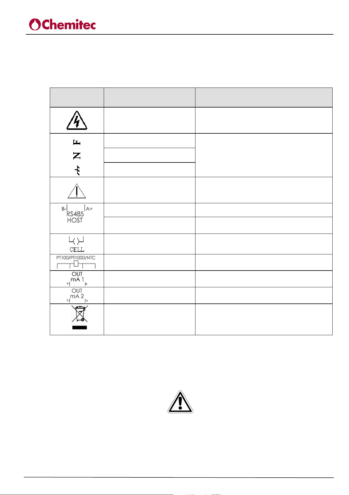
1.4 GRAPHIC SYMBOLS
The following table illustrates the drawings, the relative description and the position of all graphic
symbols present on the equipment panels and on any other equipment or external devices to which
they may be connected.
SYMBOL DESCRIPTION POSITION
DISSOLVED CONDUCTIVITY AND TEMPERATURE ANALYZER
4222
TECHNICAL MANUAL P/N XXX-0000 Rev.1 Ver.2.2
Danger symbol
A symbol located close to the clamps for
connection to power.
Phase
Neutral
Earth protection
Caution! Refer to the
documentation attached
Positive
Negative
CONDUCTIVITY
PT100/1000
Analogical output n.1
Symbols located close to the connections of the
equipment to the electricity network
A symbol located close to the points in which the
user manual should be consulted for important
information. (see paragraph CAUTION).
POSITIVE pole of the connector RS485 (A+)
NEGATIVE pole of the connector RS485 (B-)
Conductivity sensor connection
Temperature sensor connection
0/4 ÷20mA separated galvanically
Analogical output n. 2
Symbol of separate collection
of electrical and electronic
equipment.
1.5 CAUTION SYMBOL
The symbol illustrated below represents the CAUTION symbol and reminds the operator that he
should read the user manual for important information, advice and suggestions for the correct and
safe use of the equipment.
In particular, when it is positioned close to connection points to cables and peripheries, the symbol
in question refers to careful reading of the user manual for instructions related to the nature of such
cables and peripheries and the methods for correct and safe connections.
For the position of the CAUTION symbols on the equipment, refer to Chapter 2 “Commands and
Indicators, Connections” and Chapter 3 “Installation” of this user manual. The reproductions of
0/4 ÷20mA separated galvanically
Symbol placed on the top of the electronic box
4
Page 9
DISSOLVED CONDUCTIVITY AND TEMPERATURE ANALYZER
TECHNICAL MANUAL P/N XXX-0000 Rev.1 Ver.2.2
equipment panels, with relative commands, connections, symbols and labels are provided in this
chapter. Each caution symbol is accompanied by a detailed explanation of its meaning.
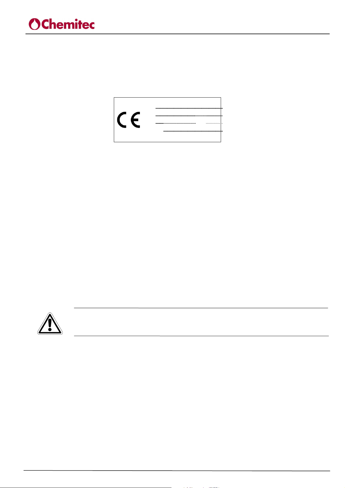
1.6 PLATE DETAILS
Mod.
4222
SN.
XXXXXXX
Volt
100-240 Vac/dc
SW Ver.
X.X
Hz
50/60
1.7 INFORMATION ON RECYCLING AND USE OF MATERIALS
CHEMITEC, in accordance with specific European regulations, aims at constant improvement of
development and of production procedures of its equipment with the objective of drastically
reducing the negative impact on the environment caused by parts, components, consumption
materials, packaging and the equipment itself at the end of its life cycle.
Packaging is conceived and produced to allow for its re-use or recovery, including recycling of the
majority of the materials and to reduce the amount of waste or residues to be disposed of, to a very
minimum. In order to assure a correct environmental impact the equipment has been designed with
the smallest circuit possible, with the lowest differentiation possible of materials and components,
with a selection of substances that guarantee utmost recycling and maximum reuse of the parts and
waste disposal free from ecological risks.
The equipment is made in such a way as to guarantee the easy separation or dismantling of the
materials containing contaminants compared with others, in particular during maintenance
operations and the replacement of parts.
CAUTION
The disposal/recycling of packaging, of consumption materials and of the equipment itself
at the end of its life cycle must be carried out in accordance with the norms and regulations
that are currently valid in the country in which the equipment is used.
4222
1.7.1 SPECIAL ATTENTION TO CRITICAL COMPONENTS
The instrument is fitted with an LCD liquid crystal display, which contains small amounts of toxic
materials.
5
Page 10
2 GENERAL DESCRIPTION
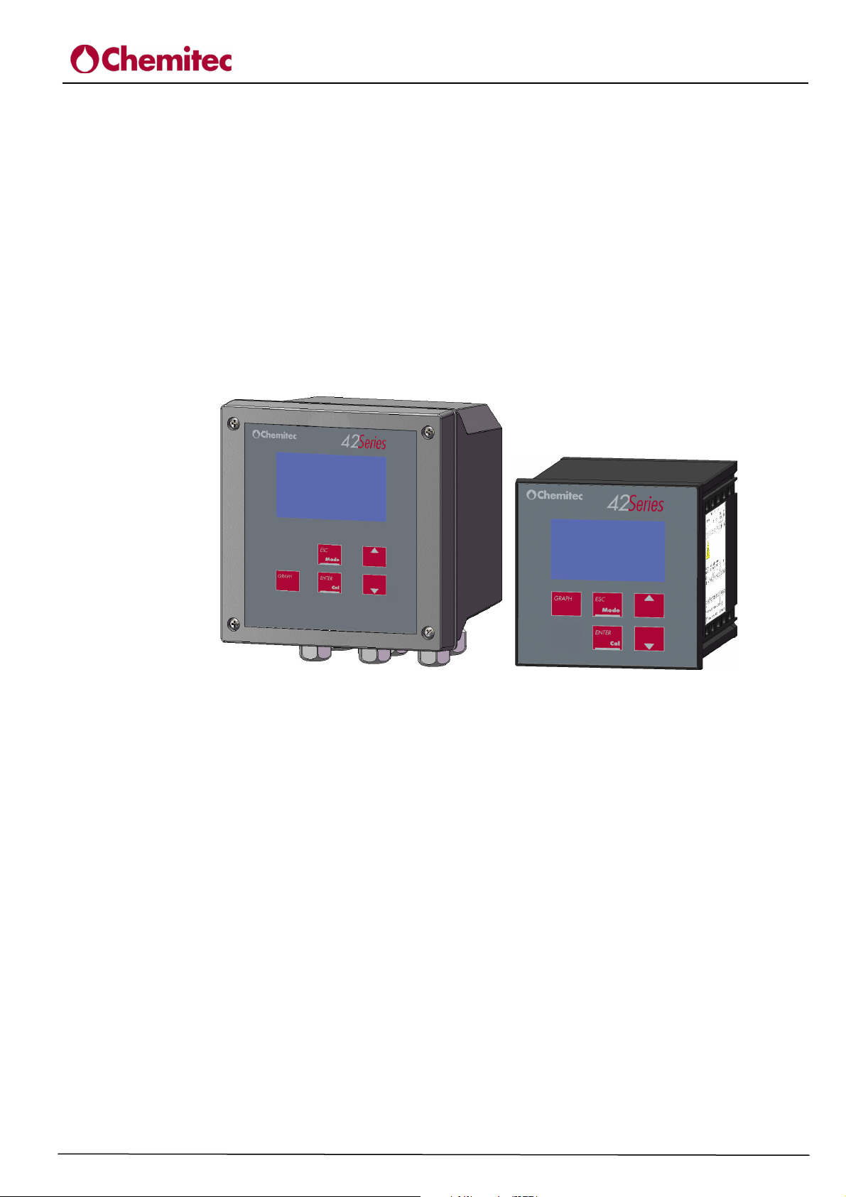
The analyser of this manual is made up of an electronic device plus a technical manual.
The device may be installed on an electrical board or to the wall at a maximum distance of 15
metres from the measuring Probe.
It is powered by the network (85÷265Vac/dc-50/60Hz) by a Switching feeder.
This equipment has been designed to analyse ON-LINE and pilot the dosage pumps for the
treatment of water in different applications:
• Waste water treatment plant
• Treatment and Discharge of Industrial Water
• Fish farm
• Primary Water, Drinking Water
DISSOLVED CONDUCTIVITY AND TEMPERATURE ANALYZER
4222
TECHNICAL MANUAL P/N XXX-0000 Rev.1 Ver.2.2
a) b)
Figure 1 – Wall (a) and panel (b) mounting Conductivity analyzer (4222)
2.1 MEASURING PRINCIPLES
The electrical conductivity measure shows the ion concentration into a solution.
More is the solution acid or even basic salt quantity, higher is the conductivity. The conductivity
measuring unit is Siemens/cm. The measuring scale for water solutions starts with the ultra-pure
water whose conductivity is 0.05 µS/cm (25°C). Conductivity of the natural water, e.g. of the
drinking water, or of the surface waters is of about 100 ... 1000 µS/cm. Some bases, as the
potassium hydroxide, with values being slightly higher than 1000 ms/cm, reach the scale upper
value.
In particular, the conductivity measuring is used in water analysis (drinking water, mineral water,
underground water, distilled water, demineralised water, boiler feed water, waste water), for
galvanic baths controls, purity controls (organics, nutrients), in the thermoelectric units (steamcondensate cycle control), in the food industries, in sugar factories, cellars, textile industry,
automatic irrigation plants, etc.
The electrical conductivity of a solution is defined as the reciprocal of the opposite resistance by a
cubic centimetre of such a solution, at a certain temperature, i.e. of the resistance being measured
between two 1 cm
Taking the 20°C temperature as a reference, the conductivity changes as per the following formula
2
surface electrodes, 1 cm. away, immersed in the above solution.
6
Page 11

DISSOLVED CONDUCTIVITY AND TEMPERATURE ANALYZER
4222
TECHNICAL MANUAL P/N XXX-0000 Rev.1 Ver.2.2
Ct = C20 [1 + α/
(T - 20)]
100
where:
Ct = conductivity to the temperature T
C20 = conductivity at 20°C
T = solution temperature
α = T coefficient at 20°C in % / °C
The α value is between 1.3 and 3.1%/°C for almost all of the electrodes and is usually 2%/°C in the
diluted solutions. Aiming at comparing the various solutions conductivity values, it is necessary to
bring all the measure back to the 20°C reference temperature using the above said formula (take
note that if the conductivity meter does not include the temperature equalizer, the measure refers to
the solution conductivity at the effective temperature; if the conductivity meter includes the
equalizer, the conductivity shown refers to that of the solution when brought to the selected
reference temperature, nevertheless the solution temperature at the measuring time). The
conductivity measure can be taken using both the electronic instrument and a measuring cell. The
cell includes two ore more electrodes. The base electrical feature of the conducimetric cells is the
“cell factor” (K) depending exclusively on the geometric dimensions of the cell and expressed in cm
(cm2 of section divided by the “cell factor”. The conductivity value is given by:
Cs = C K = C/F [2]
where:
C
s
= solution specific conductivity
C = conductivity reading on the instrument
K = cell constant, in cm-1
F = cell factor, in cm
For measuring the low conductivity values it is recommended to use high factor cells and viceversa. Another important distinction standard relates to the materials of the electrodes, i.e.:
platinum-plated (Pt spongy surface)
stainless steel (properly satin and oil free surface)
graphite
The concentric (or self-shielded) cells are then distinguished from the symmetrical electrodes. The
measure accuracy and stability might be highly reduced by the electrode polarization and
contamination. The polarization effect is due to the electrostatic charges that generates on the
electrode surfaces (even if the ion movement is due to an alternate electric field) and is particularly
detected under concentrate solutions; on the contrary, the contaminations are due to deposits,
encrustations, oil, grease, etc. The two phenomena can be (partially) reduced by using electrodes
made of a material suitable to the solution and by using a proper frequency of the oscillator
powering the cell.
2.2 MAIN CHARACTHERISTICS
• Measuring of Conductivity
• Measuring of Temperature using the NTC/PT100/PT1000 probe
• Automatic Compensation of Temperature
• Programming key pad with 5 keys
• LCD Graphic display 128x64 with background illumination
7
Page 12

DISSOLVED CONDUCTIVITY AND TEMPERATURE ANALYZER
TECHNICAL MANUAL P/N XXX-0000 Rev.1 Ver.2.2
• Internal Data Logger (flash 4 Mbit) with the possibility of graphic and table visualisation of
measurement trends
• PID adjustment
• Serial outlet RS485 MOD BUS RTU
• Data download on USB key (optional)
• 2 Programmable Analogical Outlets
• 2 Relay Outlets for intervention thresholds
• 1 Relay Outlet for Instrument Anomaly Alarm or Temperature Set Point
• 1 Relay Outlet for Probe Washing or Temperature Set Point
• 1 Digital Entrance for disabling of doses
Main hardware characteristics of the electronic device
The hardware structure of this periphery is based on the adoption of extremely new CPU CMOS
with 8 bits developed specifically for the execution of the so-called “embedded” applications.
The card uses an EEPROM to store the Set-up data and flash memories for storage of the archives
of historical data and LOG files of events.
The Card has 1 RS485 gate (opto-isolated) for local networks used for connections with local
communication devices (configuration computer, terminals and remote controls etc).
The card integrates a Real Time Clock (clock with date) that allows the software to storage figures
in a chronological order.
4222
The device has been designed to be fitted onto a panel, and is built with an IP66 protection
panel.
2.2.1 TECHNICAL CHARACTERISTICS FOR CONDUCTIVITY (PRIMARY MEASURE)
Measurement range 00.00 ÷ 20.00 / 000.0 ÷ 200.0 /
0 ÷ 2000 µS – 00.00÷20.00mS (cell K1)
Resolution ± 0.01/± 0.1/± µS ….. ± 0.01mS
Precision ± 1% F.S.
Max. load 500 Ohm
NAMUR alarm output 2.4 mA (with range 4/20mA)
2.2.2 TECHNICAL CHARACTERISTICS FOR MEASURING OF SECONDARY
TEMPERATURE
Sensor PT100/PT1000.
Measurement range 0 ÷ +50°C.
Resolution ± 0.1°C
Precision ± 1% F.S.
2.2.3 OPERATING FEATURES
Power supply 100 ÷ 240 Vac/dc 50-60 Hz
(24 Vac/dc optional)
Power consumption < 7W
Relay outputs:
Set Point ON – OFF 00.00 ÷ 20.00 / 000.0 ÷ 200.0 /
8
Page 13

DISSOLVED CONDUCTIVITY AND TEMPERATURE ANALYZER
4222
TECHNICAL MANUAL P/N XXX-0000 Rev.1 Ver.2.2
0 ÷ 2000 µS – 00.00÷20.00mS
ON – OFF Time 000 ÷ 999 Seconds
For every digital output a relay with contacts opened
normally is used. The maximum current commutable is
1 Ampere, the maximum tension commutable is
230Vac, maximum power 230VA on a resistive load
Alarm:
Function Delay, Faults and Min./Max.
Delay time 00:00 ÷ 99:99 min
Threshold disabling Enable / Disable
Relay function Closed / Open
Holding range 00.00 ÷ 20.00 / 000.0 ÷ 200.0 /
0 ÷ 2000∆ µ S – 00.00÷20.00∆mS
Holding time 00:00÷ 99:99 min
For alarm end wash digital output, a relay with
contacts opened normally is used. The maximum
current commutable is 1 Ampere, the maximum tension
commutable is 230Vac, maximum power 230VA on a
resistive load
Digital input:
Input voltage 24 Vcc /ac
Absorption 10mA max
Analogic outputs:
Outputs n.2 programmable outputs 0/4-20mA
Max. load 500 Ohm
NAMUR alarm output 2.4 mA (with range 4/20mA)
PID dosing function P – PI – PID
Proportional band 0 – 500%
Integration 0:00 – 5:00 min
Derivative 0:00 – 5:00 min
9
Page 14
DISSOLVED CONDUCTIVITY AND TEMPERATURE ANALYZER
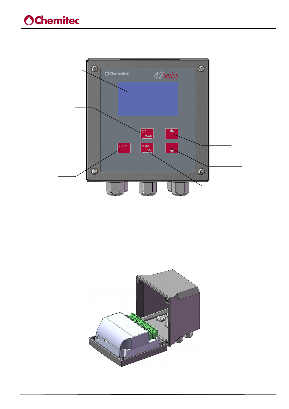
2.3 CONTROLS, INDICATORS AND CONNECTIONS
1
3
4222
TECHNICAL MANUAL P/N XXX-0000 Rev.1 Ver.2.2
2
5
6
4
Figure 2 – Wall instrument, front panel
1. Visualizer with LCD Display
2. UP key
3. ESC key
4. ENTER key
5. DOWN key
6. GRAPH key
Figure 3 – Access to the terminal box
10
Page 15
2.4 GRAPHIC DISPLAY
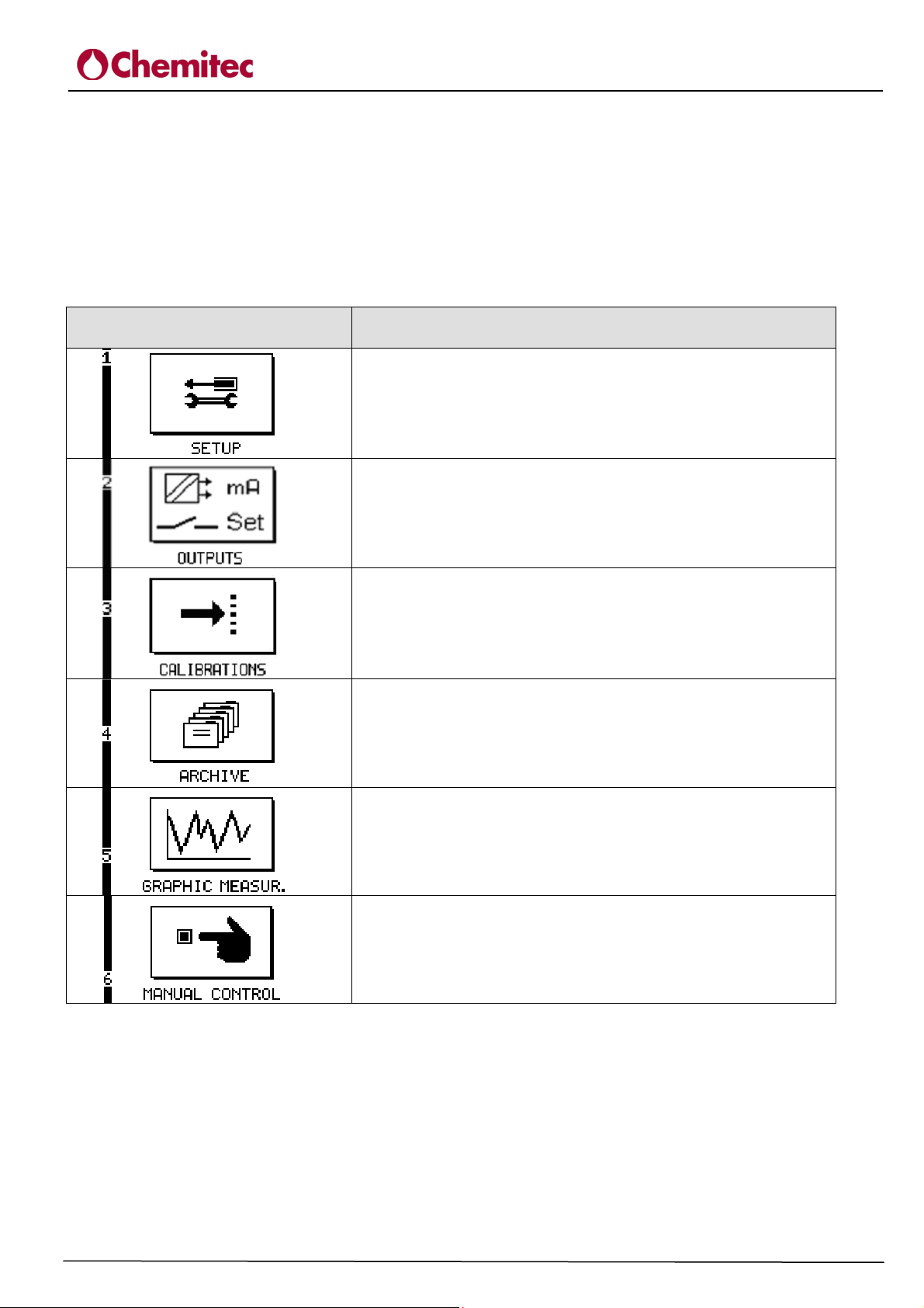
The graphic display allows for visualization of the various programming menus and, in the
measuring method (RUN), visualization of the measurements and of the state of operation.
2.4.1 LIST OF PRIMARY MENUS
The following table illustrates the symbols visualized on the display which represent the various
programming menus.
VISUALIZATION
ON THE GRAPHIC DISPLAY
SETTINGS MENU
All basic parameters for operation logics are set
OUTPUT MENU
DISSOLVED CONDUCTIVITY AND TEMPERATURE ANALYZER
TECHNICAL MANUAL P/N XXX-0000 Rev.1 Ver.2.2
DESCRIPTION
4222
Setting of analogical and digital outputs
CALIBRATIONS MENU
Calibration Procedure of the electrode
ARCHIVE MENU
Setting of the data archive and visualization mode
GRAPHICAL MEASUREMENT MENU
Visualization of archives in a graphical form
MANUAL CONTROL MENU
Manual control and activation of Inputs and Outputs
11
Page 16
DISSOLVED CONDUCTIVITY AND TEMPERATURE ANALYZER
TECHNICAL MANUAL P/N XXX-0000 Rev.1 Ver.2.2
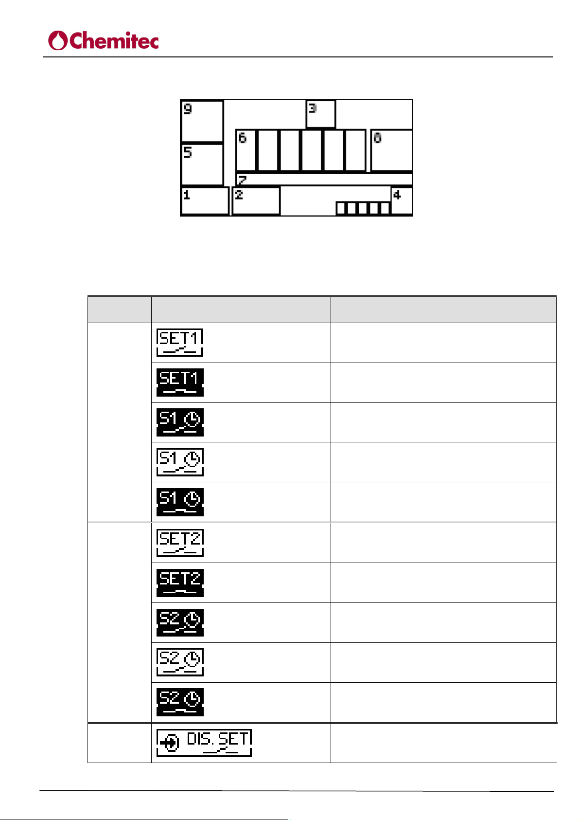
2.4.2 DIVISION OF THE GRAPHICAL DISPLAY INTO AREAS IN THE RUN METHOD
Figure 4 – Graphic display - divided up into areas
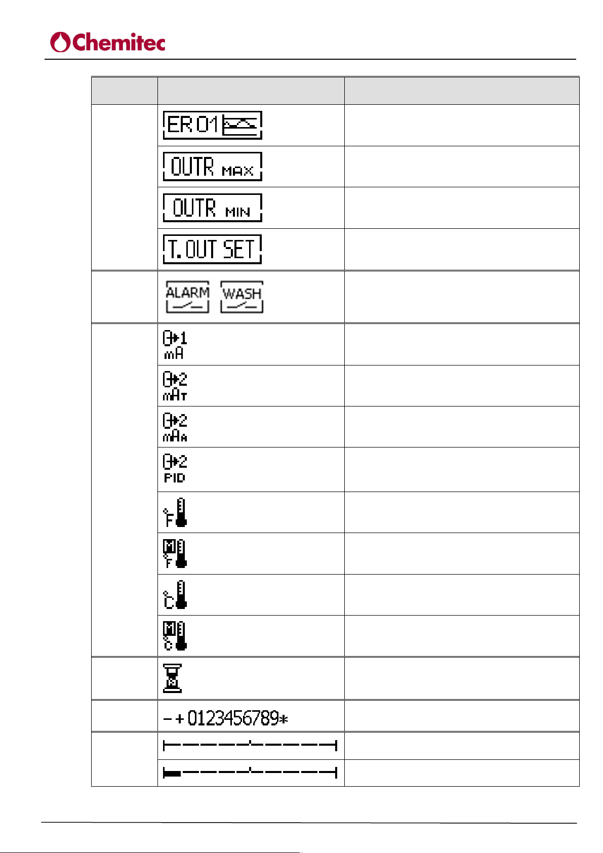
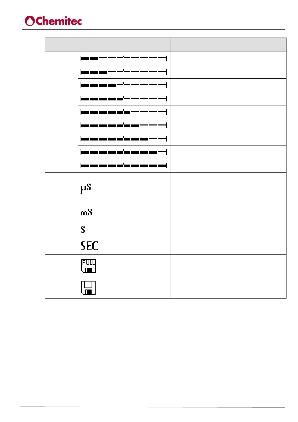
In the following table, for every area of the display indicated in figure 3, the symbols that may
appear during functioning of the device in a measurement method (RUN) are represented and
briefly described.
GRAPHIC
ZONE
VISUAL REPRESENTATION DESCRIPTION
4222
1
2
Set1 - Open Relay
Set1 - Closed Relay
Set1 – Timed
Active Threshold Relay Open
Set1 – Timed
Deactivated Threshold Relay Open
Set1 - Timed
Active Threshold Relay Closet
Set2 - Open Relay
Set2 - Closed Relay
Set2 - Timed
Active Threshold Relay Open
Set2 - Timed
Deactivated Threshold Relay Open
Set2 – Timed
1-2
12
Active Threshold Relay Closed
Disabling Set
Indicates digital entrance ON
Page 17
DISSOLVED CONDUCTIVITY AND TEMPERATURE ANALYZER
4222
TECHNICAL MANUAL P/N XXX-0000 Rev.1 Ver.2.2
GRAPHIC
ZONE
3
4
VISUAL REPRESENTATION DESCRIPTION
Stay time
Probe frozen on a value
Maximum Logical Set Exceeded
Minimum Logical Set Exceeded
Maximum dosage time exceeded
Washing stage active
Value outlet n.1 (in mA)
Value outlet n.2 of temperature (in mA)
Value outlet n.2 auxiliary (in mA)
Value outlet n.2 with PID function PID (in
mA)
5
6
7
Real temperature value (in Fahrenheit)
Manual value of temperature (in Fahrenheit)
Real temperature value (in Centigrades)
Manual temperature value (in Centigrades)
Alarm active – Alarm relay closed
Numerical
0% of the scale
10% of the scale
13
Page 18
DISSOLVED CONDUCTIVITY AND TEMPERATURE ANALYZER
4222
TECHNICAL MANUAL P/N XXX-0000 Rev.1 Ver.2.2
GRAPHIC
ZONE
8
VISUAL REPRESENTATION DESCRIPTION
20% of the scale
30% of the scale
40% of the scale
50% of the scale
60% of the scale
70% of the scale
80% of the scale
90% of the scale
100% of the scale
Conductivity measurement unit
9
Conductivity measurement unit
Conductivity measurement unit
Seconds during stabilization
Archive full
Storage of Data
14
Page 19
3 INSTALLATION
Although the unit is suitable for installation in outdoor environments, it is recommended to avoid
direct exposure to sun and weather. Before installing the 4222 carefully read the instructions
provided below.
3.1 COMPOSITION OF THE SUPPLY
The supply consists of just one package which contains the following parts:
• 1 electrical control and command panel PN ............?????
• 1 Technical Manual PN ............?????
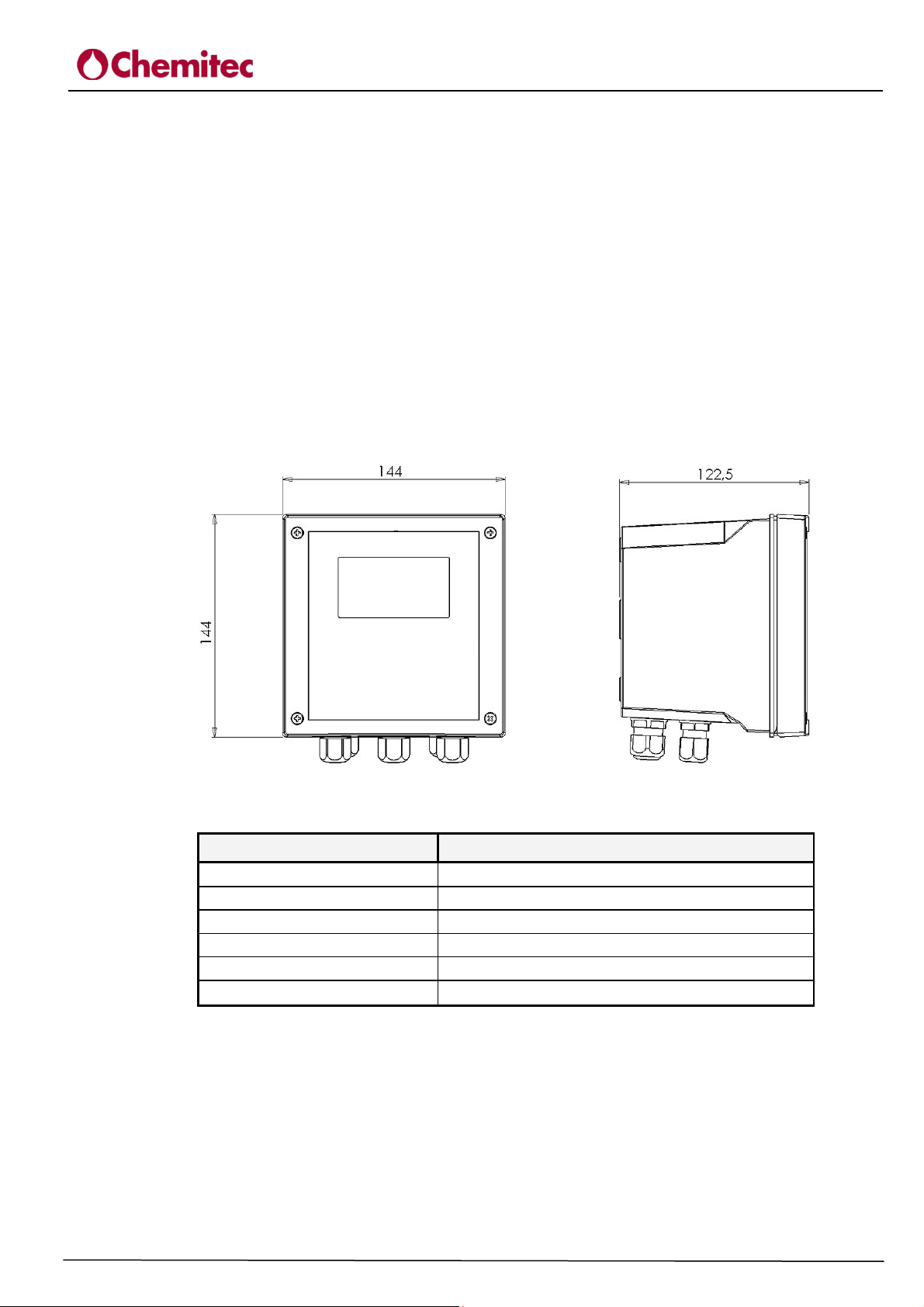
3.1.1 INSTALLATION OF WALL MOUNTED DEVICE
The wall must be completely smooth in order to allow for perfect adhesion of the device.
CONDUCTIVITY AND TEMPERATURE ANALYZER
4222
TECHNICAL MANUAL P/N XXX-0000 Rev.1 Ver.2.2
Figure 5 – Dimensions and encumbrance of the wall mounted device
Mechanical Dimensions
Dimensions (L x H x P)
Fixing depth
Material
Mounting
Weigth
Frontal Panel
4222 Wall mounted
144x144x122,5mm
122,5mm
ABS Grey RAL 7045
Wall
1 Kg
Policarbonate UV Resistant
Open the instrument, open the pre-shaped holes and fix the instrument itself to the wall. Use the
provided plastic caps to close the holes.
The terminal box for connections is located on the bottom of the gear case and it is necessary to
keep it separated from other equipment by at least 15 cm. in order to make it easier to use. Keep
away from water drips and/or sprays of water from adjacent areas in order to safeguard the
instrument during programming or calibration stages.
15
Page 20
3.1.2 INSTALLATION OF 96X96 ELECTRICAL PANEL DEVICE
The wall must be perfectly smooth in order to allow for perfect adhesion of the electrical panel close
to the device.
The net depth of the panel must be at least 130 mm.
The thickness of the panel must not exceed 5 mm.
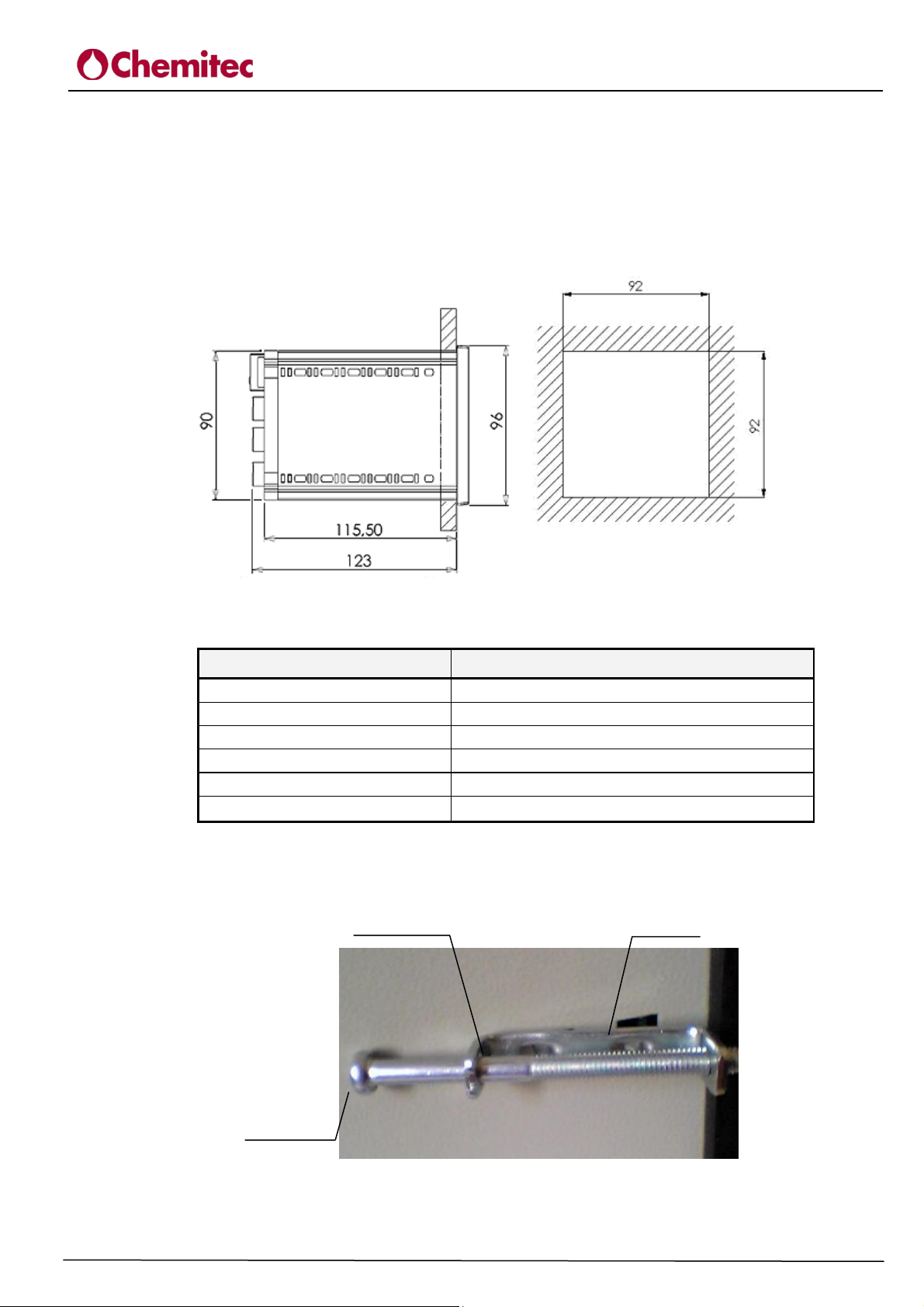
The perforation DIMA must comply with the following layout:
CONDUCTIVITY AND TEMPERATURE ANALYZER
4222
TECHNICAL MANUAL P/N XXX-0000 Rev.1 Ver.2.2
Figure 6 – Encumbrance and Dima for perforation of the panel
Mechanical Dimensions
Dimensions (L x H x P)
Fixing depth
Material
Mounting
Weight
Frontal Panel
4222 96x96 Panel Mounted
96x96x115,5 mm
130mm
ABS Black
Panel
0.7 Kg
Policarbonate UV Resistant
Fixing of the gear case to the panel is carried out using two brackets (1)included in the standard
supply, which are inserted into the housings (2) and fixed into position using the relative screws
(3).
1
2
3
Figure 7 – Fixing bracket of the Device to the Panel
Keep free from dripping and/or sprays of water from adjacent areas.
16
Page 21
CONDUCTIVITY AND TEMPERATURE ANALYZER
TECHNICAL MANUAL P/N XXX-0000 Rev.1 Ver.2.2
3.1.3 INSTALLATION OF 144X144 ELECTRICAL PANEL DEVICE
The wall must be perfectly smooth in order to allow for perfect adhesion of the electrical panel close
to the device.
The net depth of the panel must be at least 130 mm.
The thickness of the panel must not exceed 5 mm.
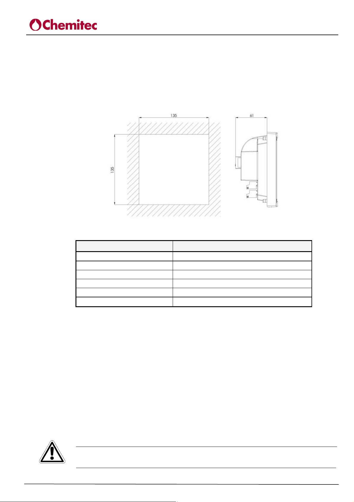
The perforation DIMA must comply with the following layout:
4222
Figure 8 – Encumbrance and Dima for perforation of the panel
Mechanical Dimensions
Dimensions (L x H x P)
Fixing depth
Material
Mounting
Weight
Frontal Panel
The locking of the control unit to the panel is made through the mounting backplate, which is fixed
to the panel on the inner side, using the apposite screws.
3.1.4 CONNECTIONS TO THE POWER SUPPLY
If possible avoid any cables destined for high power use to be positioned close to the device as they
may cause faults of an inductive nature to the analogical section of the instrument.
Apply a tension alternating between 100Vac and 240Vac 50/60 Hz or, according to details on the
identification plate, the most stabilised tension possible.
Avoid at all costs connections to power supplies that have been rebuilt, for example, with the help
of transformers in which this rebuilt power supply will feed other systems beyond the device
(perhaps of an inductive kind) because, in this way, high tension spikes will be created and once
they are irradiated it becomes very difficult to block and/or eliminate them.
CAUTION
The electric line must be fitted with a suitable life-saving device and magneto-thermal, in
compliance with correct installation norms.
4222 144x144 Panel Mounted
144x144x86,5mm
70mm
ABS Grey RAL 7045
Panel
0.7 Kg
Policarbonate UV Resistant
17
Page 22
In any case it is always best to check the quality of the Ground connection. It is very common to
User
find Ground connections, mainly in industrial environments, that are generators themselves of
disturbances: in the case of any doubts on quality a connection to a rod dedicated to the device plant
is recommended.
3.1.4.1 Electrical Connections to the dosage systems (Users)
CAUTION
Before starting connections between the Device and the external Users, make sure that the
electrical panel is switched off and the cables from the Users are not under tension.
“Users” mean the outlets and relays used in the device
− (SET1) for the Dosage Pump or control command
− (SET2) for the Dosage Pump or control command
− (ALARM) the alarm command transmitted by the instrument to the siren and/or flashing
light
− (WASH) electrode washing command
CAUTION
Each relay contact can support, on a resistive load, a maximum current of 1 Ampere with a
max. of 230V, therefore a total power of 230VA
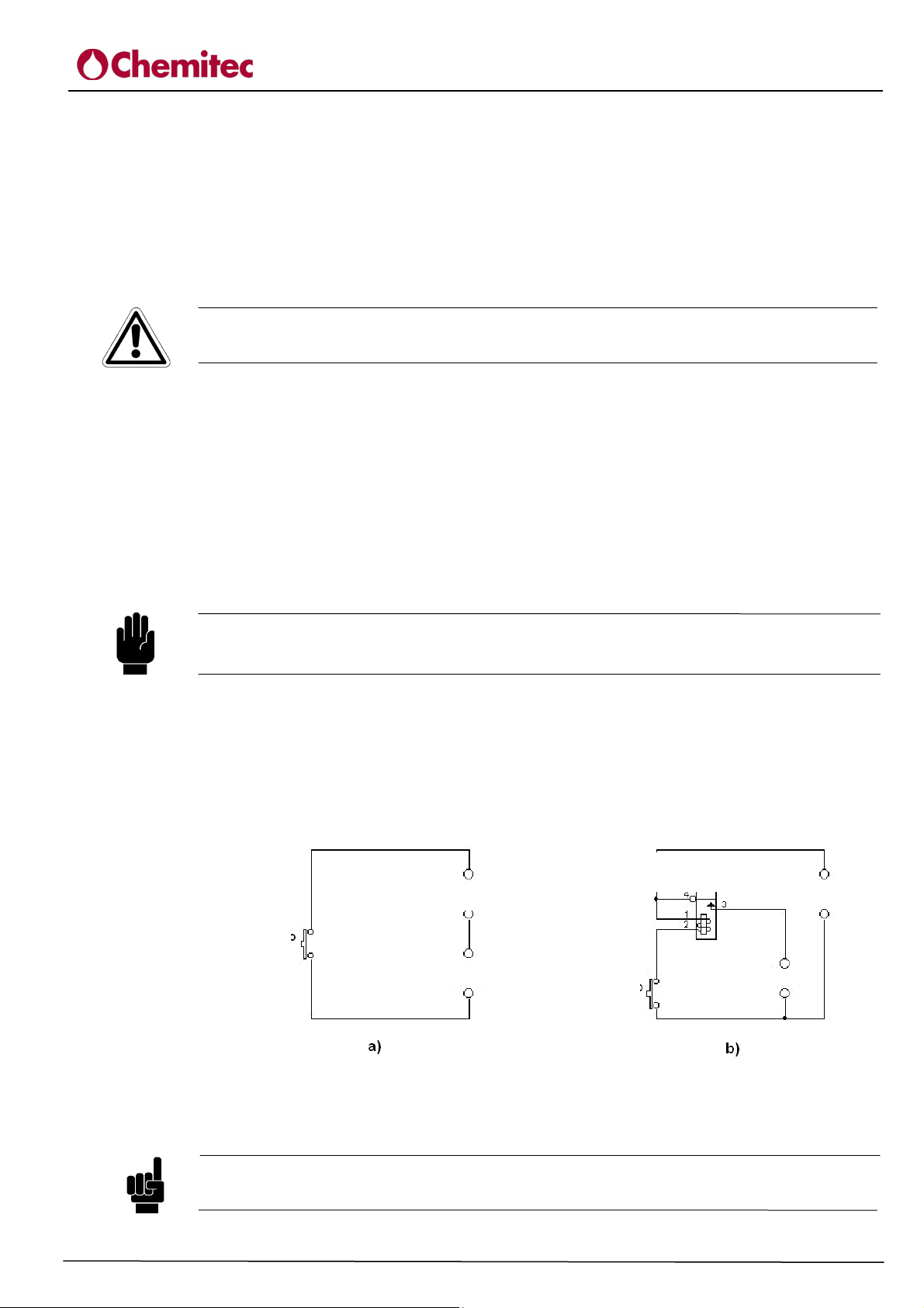
In the case of higher levels of power it is best to carry out connections as indicated in the layout of
fig. 9-b)
If the load to be handed is of low power or of a resistive nature, the layout indicated in Fig. 9-a) can
be used.
Loads lower then 230VA Loads higher then 230VA
CONDUCTIVITY AND TEMPERATURE ANALYZER
4222
TECHNICAL MANUAL P/N XXX-0000 Rev.1 Ver.2.2
Remote control
SET1
contac
Power supply
User
switch/Relay
SET1
contac
Power supply
Figure 9 Examples of connection with users
NOTE
The layouts indicated above are typically indicative as details of all of the protection and
safety devices necessary are missing.
18
Page 23
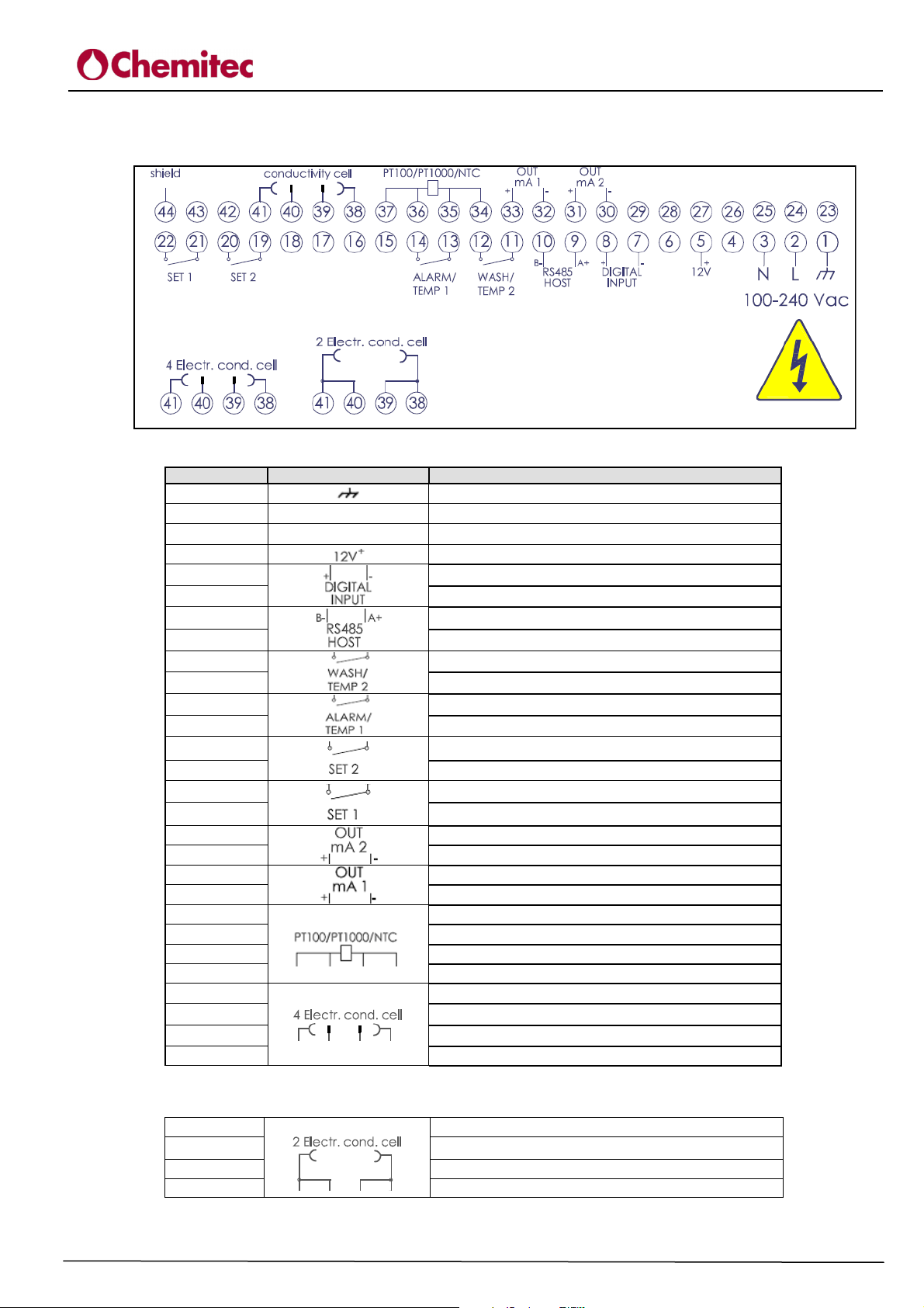
3.1.4.1.1 Connection terminal box for wall mounted 4222
Figure 10 Connections terminal box (wall mounted)
CLAMP Nr. GRAPHIC DESCRIPTION
1
2
3
5
7
8 Digital input (+)
9
10 RS485 (B-)
11
12 Relay for Wash and Temp (N.O. contact)
13
14 Relay for Alarm and Temp (N.O. contact)
19
20 Relay for Set Point 2 (N.O. contact)
21
22 Relay for Set Point 1 (N.O. contact)
30
31 Output mA2 (+)
32
33 Output mA1 (+)
34
35 NTC / PT100 / PT1000 Signal Cable
36 NTC / PT100 / PT1000 Signal Cable
37 NTC / PT100 / PT1000 Common Cable
38
39 Signal Return 1 (4 Wires)
40 Signal Return 2 (4 Wires)
41 Driving 2 (4 Wires)
L
N
Power supply (Earth)
Power supply (Neutral)
Power supply (Phase)
Probe Supply (+12V)
Digital input (-)
RS485 (A+)
Relay for Wash and Temp (N.C. contact)
Relay for Alarm and Temp (N.C. contact)
Relay for Set Point 2 (N.C. contact)
Relay for Set Point 1 (N.C. contact)
Output mA2 (-)
Output mA1 (-)
NTC / PT100 / PT1000 Common Cable
Driving 1 (4 Wires)
In case of 2 wires conductivity probe connection:
38
39 Signal 1 (2 Wires)
40 Signal 2 (2 Wires)
41 Signal 2 (2 Wires)
Signal 1 (2 Wires)
CONDUCTIVITY AND TEMPERATURE ANALYZER
4222
TECHNICAL MANUAL P/N XXX-0000 Rev.1 Ver.2.2
19
Page 24
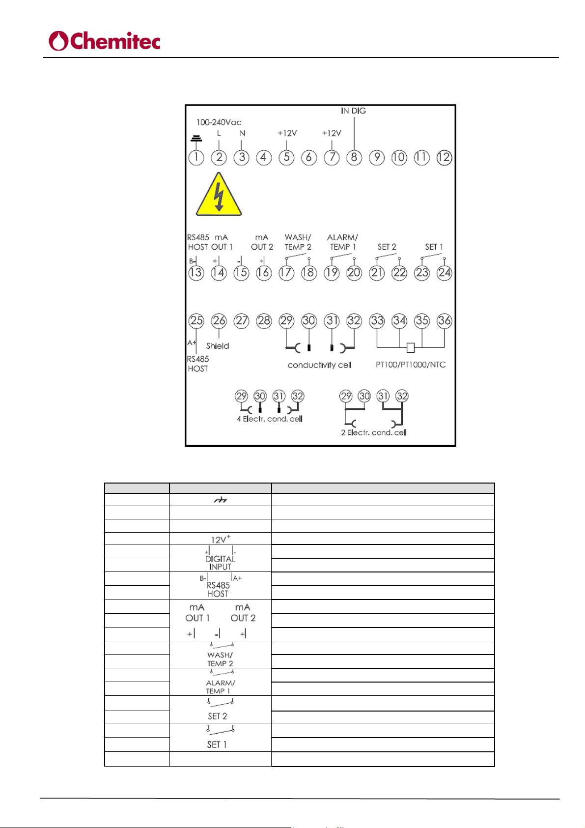
3.1.4.1.2 Connection terminal box for panel mounted 4222
CONDUCTIVITY AND TEMPERATURE ANALYZER
4222
TECHNICAL MANUAL P/N XXX-0000 Rev.1 Ver.2.2
Figure 11 Connections terminal box (panel mounted)
CLAMP Nr. GRAPHIC DESCRIPTION
1
2
3
5
7
8 Digital input (+)
13
25 RS485 (A+)
14
15 Output mA1 – mA2 (-) (common)
16 Output mA2 (+)
17
18 Relay for Wash and Temp (N.O. contact)
19
20 Relay for Alarm and Temp (N.O. contact)
21
22 Relay for Set Point 2 (N.O. contact)
23
24 Relay for Set Point 1 (N.O. contact)
26
L
N
Shield
Power supply (Earth)
Power supply (Neutral)
Power supply (Phase)
Probe Supply (+12V)
Digital input (-)
RS485 (B-)
Output mA1 (+)
Relay for Wash and Temp (N.C. contact)
Relay for Alarm and Temp (N.C. contact)
Relay for Set Point 2 (N.C. contact)
Relay for Set Point 1 (N.C. contact)
Shield
20
Page 25
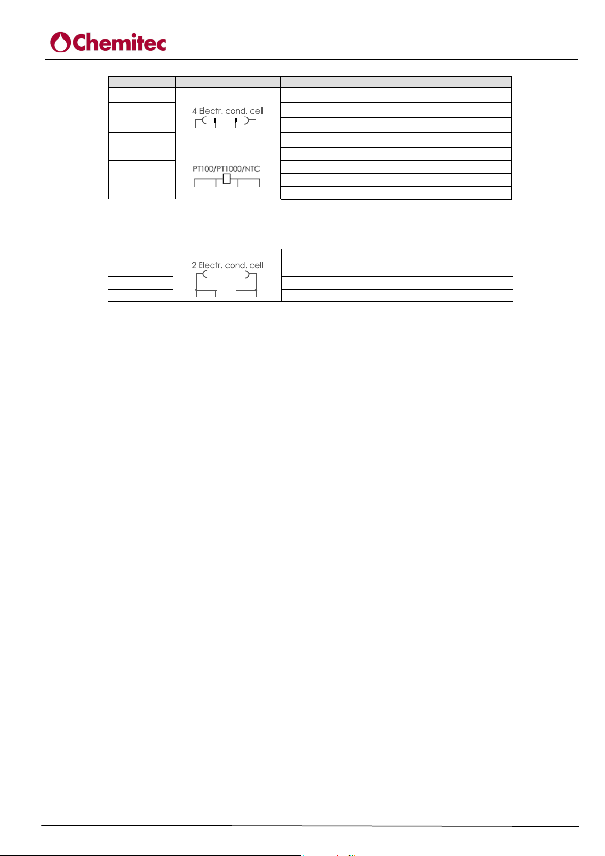
CLAMP Nr. GRAPHIC DESCRIPTION
29
30 Signal 2 Return (4 wires)
31 Signal 1 Return (4 wires)
32 Driving 1 (4 wires)
33
34 NTC / PT100 / PT1000 Signal Cable
35 NTC / PT100 / PT1000 Signal Cable
36 NTC / PT100 / PT1000 Common Cable
In case of 2 wires conductivity cell connection:
29
30 Signal 2 (2 Wires)
31 Signal 1 (2 Wires)
32 Signal 1 (2 Wires)
3.1.4.2 Connections to the Power Supply
Once you have made sure that the tension complies with the one indicated in the previous
paragraphs, connect the electrical power line to the clamps marked by connecting the clamp with the
relative symbol to earth.
CONDUCTIVITY AND TEMPERATURE ANALYZER
TECHNICAL MANUAL P/N XXX-0000 Rev.1 Ver.2.2
Driving 2 (4 wires)
NTC / PT100 / PT1000 Common Cable
Signal 2 (2 Wires)
4222
3.1.5 CONDUCTIVITY PROBE CONNECTION
Switch the instrument off.
Connect the electrode cables to the meter terminal box. Observe the number codes on the adhesive
label placed under the electronics container cover or refer to the manual (see 3.1.3.1.1 e 3.1.3.1.2).
21
Page 26
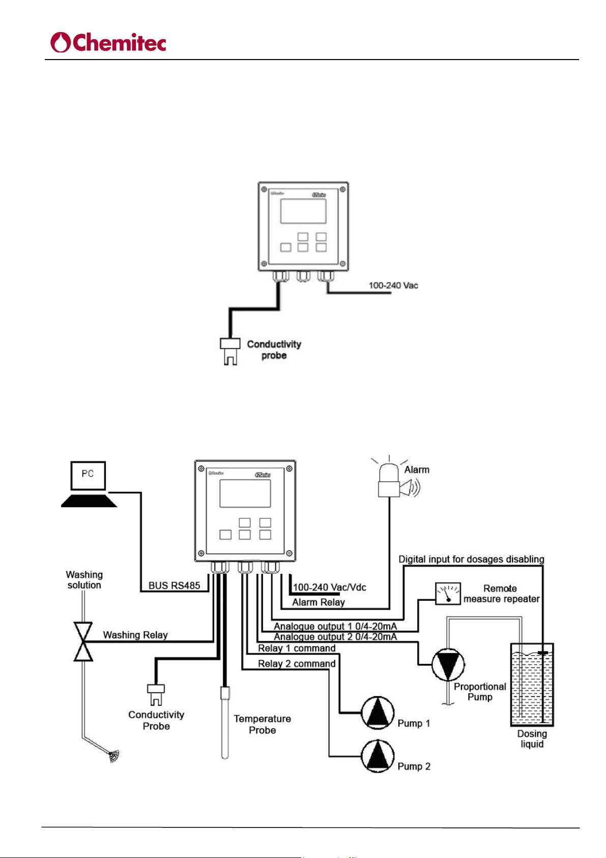
4 METHODS OF USE
4.1 COMPOSITION OF THE MEASURING SYSTEM
4.1.1 MINIMUM CONFIGURATION
CONDUCTIVITY AND TEMPERATURE ANALYZER
4222
TECHNICAL MANUAL P/N XXX-0000 Rev.1 Ver.2.2
Figure 12 Minimum configuration
4.1.2 MAXIMUM CONFIGURATION
Figure 13 Maximum Configuration
22
Page 27
4.2 START UP OF THE SYSTEM
Once the electronic device and the measuring probe (Conductivity) have been connected,
programming of the software must be carried out in order to determine “personalisation” of
parameters for correct use of the equipment.
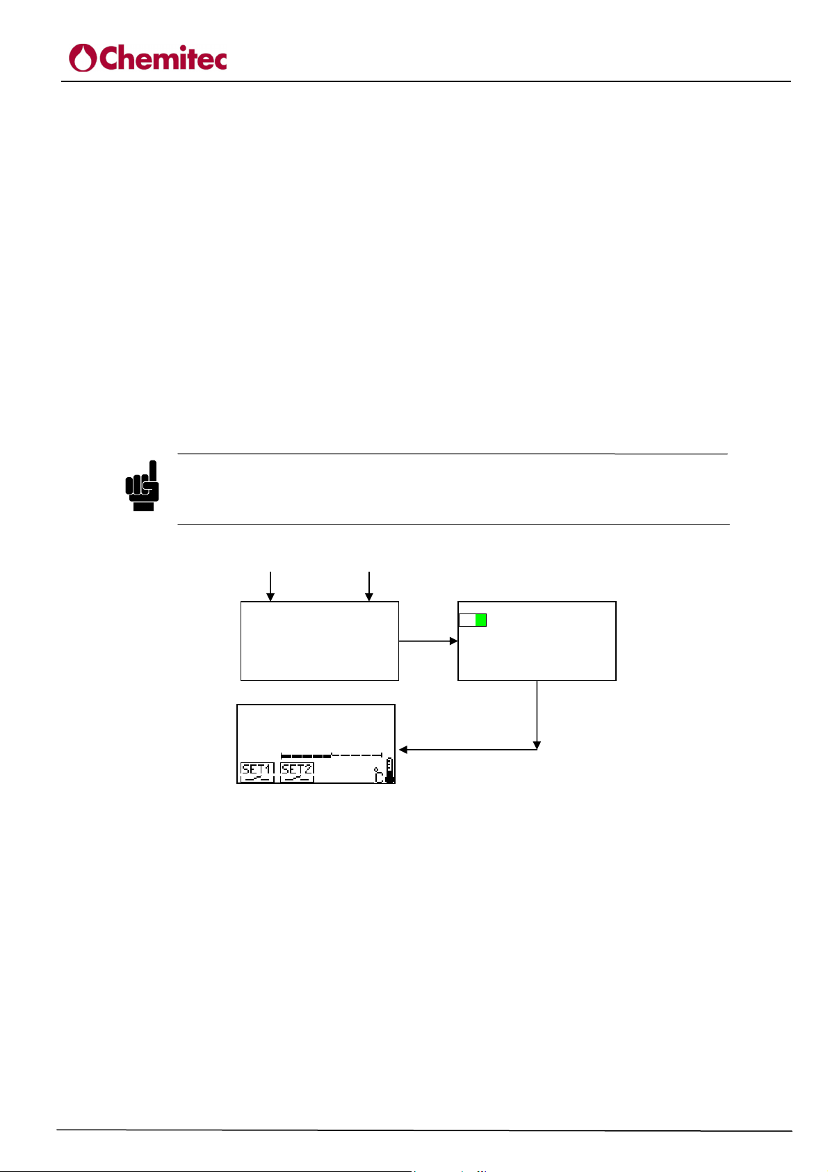
Turn on the equipment by connecting it to the mains, the device does not have a power supply
switch.
4.2.1 MENU FUNCTIONS AT START
When the equipment is turned on, it is possible to use some keys to intervene on programming
functions not present in the SETUP.
(See paragraphs 4.3.1; 4.3.2; 4.3.3)
4.2.1.1 Contrast adjustment
Using the same procedure, but keeping the DOWN button pressed, the display contrast adjustment
window will appear.
During this operation release the DOWN button immediately after the first acoustic beep,
otherwise the contrast will go quickly to 0% and the display will be completely white. In
order to reset the correct level, simply press the UP key to the desired value.
Using the UP and DOWN keys it is possible to adjust the contrast percentage.
COND 4222
WAIT…
DOWN 220V
Ver 1.0
1.0 mS
20.5
Figure 14 –Contrast Function Flow-Chart
NOTE
Contrast Control
88
ENTER
CONDUCTIVITY AND TEMPERATURE ANALYZER
4222
TECHNICAL MANUAL P/N XXX-0000 Rev.1 Ver.2.2
Subsequently pressing ENTER, the RUN visualisation will be activated.
4.3 INTRODUCTION OF OPERATIVE PARAMETERS – THE USE OF KEYS
In order to introduce/modify operative figures and to carry out calibration procedures, use the menus
visualised on the display through the 4 function keys located on the front panel of the device.
When turned on the apparatus will automatically position itself in a measuring method – the RUN
function. By pressing the ESC key the programming method will be available through the first
menu “ 1 SETTINGS".
Using the UP and DOWN keys the various menus and submenus can be scrolled and information
can be modified (increase/reduction).
Using the ENTER key access will be provided to the submenus for the input of information and the
variations made will be confirmed.
23
Page 28
By pressing the ESC key the screen will go back to the menu or to the previous function and any
Serial NO.
Serial NO.
Serial Number
Serial Number
Serial Number
Serial Number
variations made will be cancelled.
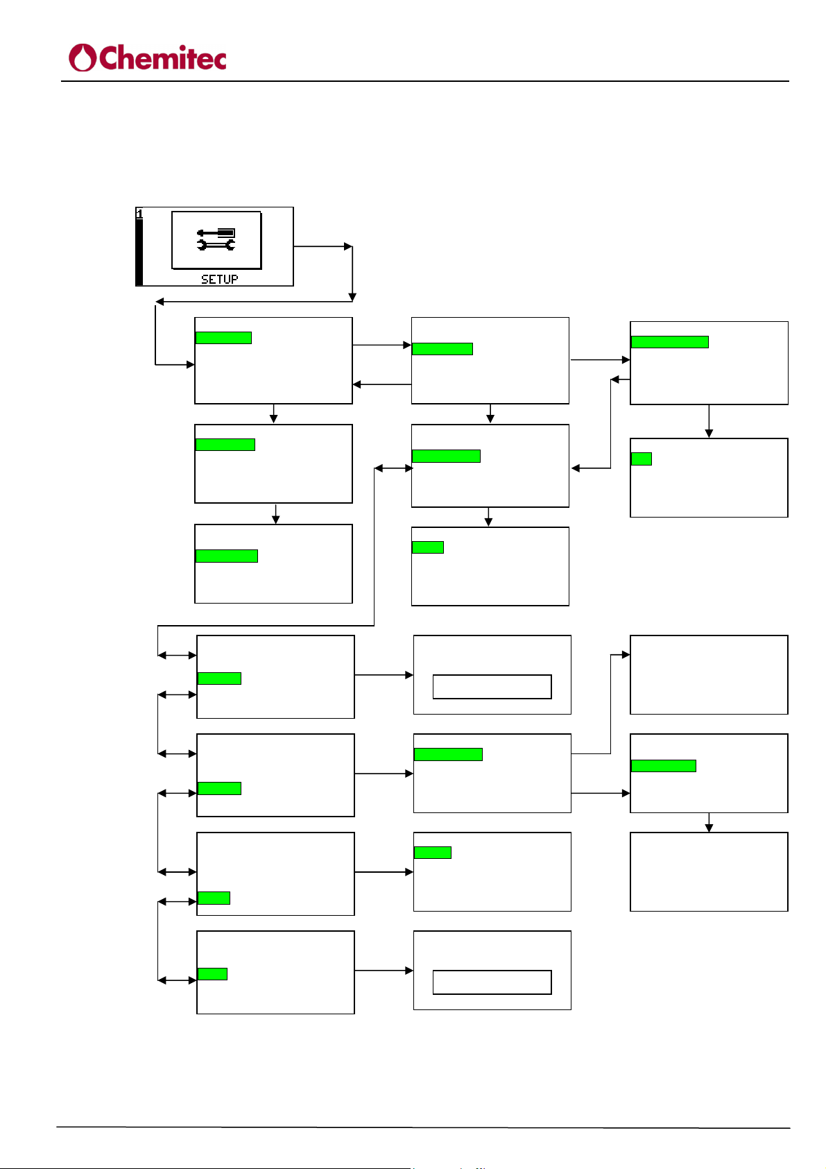
4.3.1 SETUP MENU (TEMPERATURE – SYSTEM SETUP)
ENTER
+
DOWN
(A1)
1. 0 IMPOSTAZIONI
Temperature
Setup System
Digital Input
Select measure
Measur. setup
ENTER
1.10 TEMPERATURE
Temp. Comp. AUT
Manual Temp. +025°C
Measur unit °C
ENTER
1.10 TEMPERATURE
Temp. Comp. AUT
Manual Temp. +025°C
Measur unit °C
DOWN
UP
UP/DOWN
(A2)
1. 0 IMPOSTAZIONI
Temperature
Setup System
Digital Input
Select measure
Measur. setup
ENTER
1.30 SETUP SYSTEM
Date/hour System
Communication
Language
Password
Display
ENTER
1.220 COMMUNICATION
ID Item 01
Baud rate 9600
CONDUCTIVITY AND TEMPERATURE ANALYZER
4222
TECHNICAL MANUAL P/N XXX-0000 Rev.1 Ver.2.2
1.20 SETUP SYSTEM
ENTER
DOWN
Date/hour System
Communication
Language
Password
Display
ENTER
DATE/HOUR
Day 09
Month 03
Year 2010
Hour 17
Minute 11
UP/DOWN
UP/DOWN
UP/DOWN
UP/DOWN
1.20 SETUP SYSTEM
Date/hour System
Communication
Language
Password
Display
1.20 SETUP SYSTEM
Date/hour System
Communication
Language
Password
Display
1.20 SETUP SYSTEM
Date/hour System
Communication
Language
Password
Display
1.20 SETUP SYSTEM
Date/hour System
Comunicazione
Lingua
Password
Display
ENTER
ENTER
ENTER
ENTER
1.23 SETUP SYSTEM
Language
Password State
New Password
Eng lish
1.240 PASSWORD
1.250 DISPLAY
Contrast 88
Back Lighten NO
1.26 SETUP SYSTEM
Serial NO
123 4 5
ENTER
UP/DOWN
1.241 PASSWORD
Password State
Password: 0
1.240 PASSWORD
Password State
New Password
ENTER
1.242 PASSWORD
New Password
Password: 0
A1) Temperature
The Unit of Measurement function allows for the value of the temperature to be visualised in
Centigrade or Fahrenheit. Centigrades are set as a default.
24
Page 29

CONDUCTIVITY AND TEMPERATURE ANALYZER
TECHNICAL MANUAL P/N XXX-0000 Rev.1 Ver.2.2
A2) Setup System
In this part of the programme which is divided up into 5 functions, the basic functioning parameters
of the instrument are set.
Description of the functions:
DATE/HOUR SYSTEM
Setting of the DATE and TIME of the system that will be memorised every time that figures are
viewed in a historical perspective.
COMMUNICATION
The instrument has a serial port in RS485 which is separated galvanically and can be used for
dialogue with a HOST system using the standard protocol MOD BUS RTU. Through the serial port
it is possible to visualise the real time status, programme all of the Set-Up and downloading all of
the archives of the instrument.
The Communication Set-up function is used to programme the serial port and is divided up into two
settings:
ID Instrument: A numerical address from 1 to 99 to which the instrument will reply. The default is
01.
Baud Rate: Speed of the RS485 serial which can be programmed at between 1200 and 38400. The
default is 9600.
LANGUAGE
It is possible to select the language used by the Software between: Italian, English, French, Spanish
and German.
PASSWORD
At this stage it is possible to activate and programme for access to the instrument. Once activated,
each time that the programming stage is accessed the access password will be requested.
The password is made up of a 4 figure number. The default is 2002 which will always remain
active even if a new password is programmed.
In order to access the step “Password Status” or “New Password”, the existing password must be
inserted and then the new input can be carried out.
DISPLAY
Contrast: It allows for the definition of a greater or lower contrast of the display according to the
temperature in which the instrument is operating.
Background illumination: At this stage you can decide whether or not to maintain background
illumination or to switch it off one minute after having released the key.
By programming YES the background illumination stays on, by programming ON it switches off
automatically. NO is programmed as a default.
SERIAL NUMBER
In this part of the programme the serial number of the instrument is shown.
4222
25
Page 30
Active
Abilitation
(B1)
(B2)
(C1)
(D2)
(D1)
(D3)
(D4)
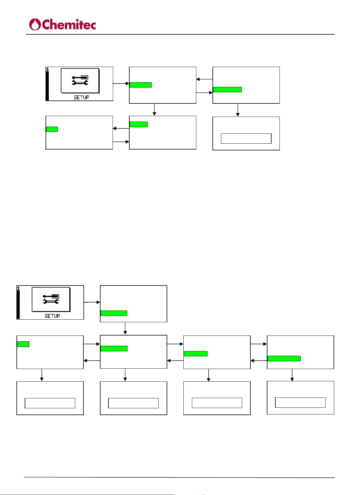
4.3.2 SETUP MENU (DIGITAL INPUT – SELECT MEASURE)
CONDUCTIVITY AND TEMPERATURE ANALYZER
4222
TECHNICAL MANUAL P/N XXX-0000 Rev.1 Ver.2.2
1.50 DIGITAL INPUT
Dis. SET
Active HIGH
B1) Digital input: Abilitation
In this function it is possibile to assign the digital input.
Setting “Dis. SET” the digital input is assigned to the SET POINT disabilitation.
Setting “WASH” the digital input is assigned to the WASH.
B2) Digital input: Active
This function allows to set the direction of the input: if active when the input goes HIGH or LOW.
Setting “HIGH” the digital input is active when the input itself is powered.
Setting “LOW” the digital input is active when the input itself is not powered.
C1) Select measure
Allows to select the measuring unit , choosing from Siemens and TDS (Total Dissolved Salts).
ENTER + DOWN
Temperature
Setup System
Digital input
Select measure
Setup measure
UP
Abilitation Dis. SET
DOWN
1. 0 SETUP
ENTER
1.30 DIGITAL INPUT
ON
UP
Temperature
Setup System
Digital Input
DOWN
Select measure
Setup measure
1. 0 SETUP
1.4 SETUP
SIE M E NS
ENTER
4.3.3 SETUP MENU (SETUP MEASURE)
Range
Constance cell
Measur. Unit
K-TDS Coefficient
1.50 SETUP
ENTER
1.51 SETUP
0 – 20 0 mS k = 1 cm
ENTER + DOWN
DOWN
Temperature
Setup System
Digital Input
Select measure
Measur. Setup
UP
Range
Constance cell
Measur. Unit
K-TDS Coefficient
Constance cell
1. 0 SETUP
ENTER
1.50 SETUP
ENTER
1.52 SETUP
D1) Range
Allows to set the range in wich the probe works, acording to the assigned measuring unit and
constance cell.
If the measuring unit is Siemens and the constance cell is 1, range is selectable between:
UP
Range
Costante di cella
Measur. Unit
K-TDS Coefficient
DOWN
Measur. Unit
1.50 SETUP
1.53 SETUP
ppm
ENTER
UP
Range
Constance cell
Measur. Unit
K-TDS Coefficient
DOWN
k-TDS Coefficient
1.50 SETUP
1.54 SETUP
0,5 0
ENTER
26
Page 31

CONDUCTIVITY AND TEMPERATURE ANALYZER
TECHNICAL MANUAL P/N XXX-0000 Rev.1 Ver.2.2
4222
• 0-200 mS
• 0-20 mS
• 0-2000 µS
• 0-200 µS
• 0-20 µS
If the measuring unit is Siemens and the constance cell is 0,1, range is selectable between:
• 0-2 S
• 0-200 mS
• 0-20 mS
• 0-2000 µS
• 0-200 µS
If the measuring unit is Siemens and the constance cell is 10, range is selectable between:
• 0-20 mS
• 0-2000 µS
• 0-200 µS
• 0-20 µS
• 0-2 µS
If the measuring unit is Siemens and the constance cell is 10, range is selectable between:
• 0-20 µS
• 0-2 µS
If the measuring unit is TDS and the constance cell is 1, range is selectable between:
• Ultra High
• High
• Medium
• Low
• Ultra Low
If the measuring unit is TDS and the constance cell is 0,1, range is selectable between:
• Ultra High
• High
• Medium
• Low
• Ultra Low
If the measuring unit is TDS and the constance cell is 10, range is selectable between:
• Ultra High
• High
• Medium
• Low
• Ultra Low
If the measuring unit is TDS and the constance cell is 100, range is selectable between:
• Low
• Ultra Low
27
Page 32
D2) Constance cell
Alarm
UP
Allows to set the value of the della Constance cell, choosing between 0.1, 1, 10 and 100.
D3) Measur. Unit
This menu is only selectable if the invoice “TDS” in the “Select Measure” menu (C1) is selected
and allows to set the measuring unit of the TDS; it’s possible to choose between ppm and mg/l.
D4) K-TDS Coefficient
This menu is only selectable if the invoice “TDS” in the “Select Measure” menu (C1) is selected
and allows to set the multiplying coefficient of the conductivity value to find the corrsponding TDS
(Total Dissolved Salts) value.
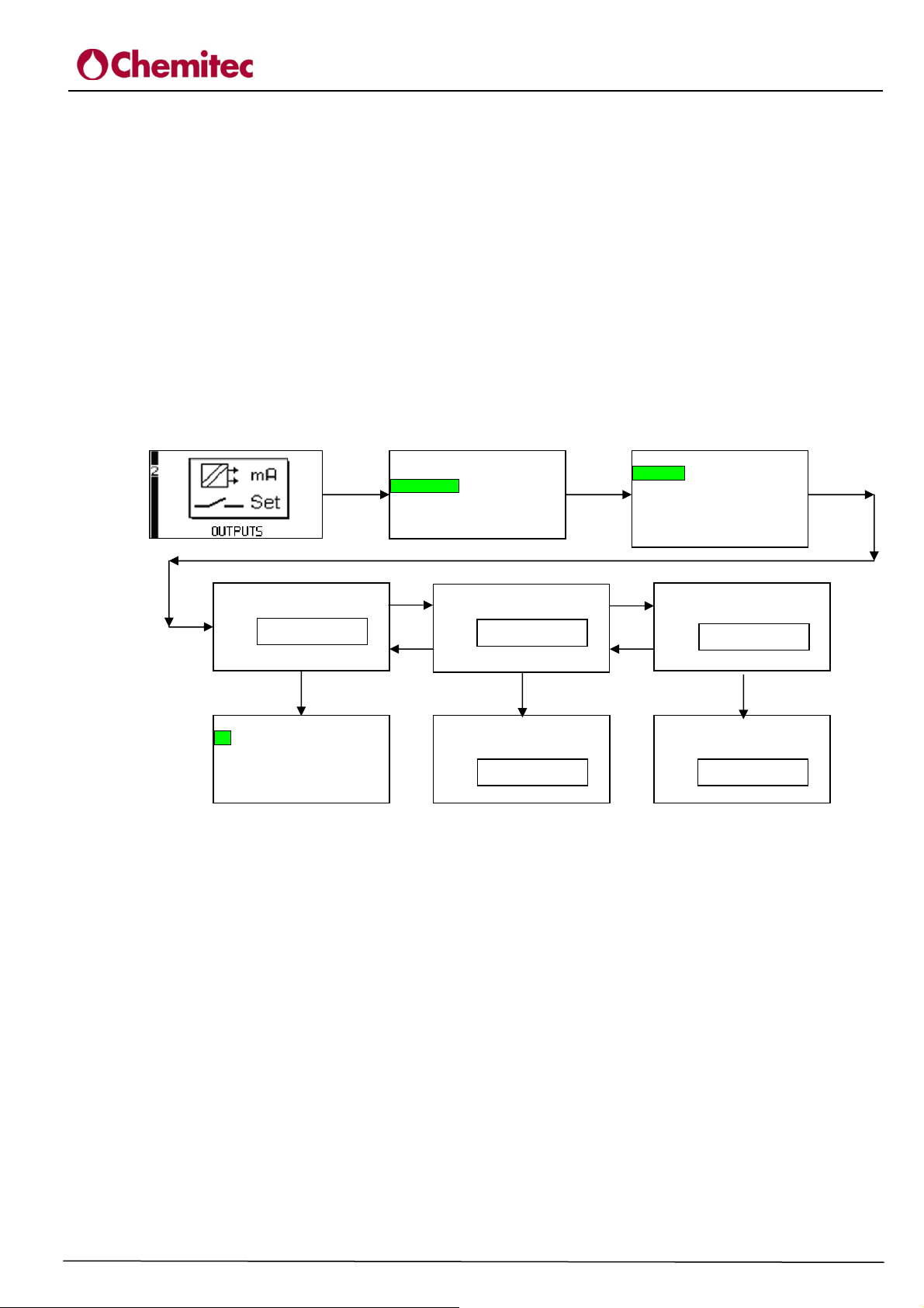
4.3.4 OUTPUTS MENU (RELAY OUTPUTS – SET POINT 1)
ENTER
Relay Outputs
Current Output
Setup PID
2.0 USCITA
ENTER
2.1 USCITE RELAY
Set Point 1
Threshold
UP
DOWN
(E1)
(E2)
2.1 USCITE RELAY
Set Point 1
PID-PWM
ENTER
2.11 SET POINT 1
ON 0.0 mS
OFF 0.0 mS
ON Time +000 Sec
OFF Time +000 Sec
ENTER
2.112 PID RELAY 1
Period
0002 sec
The programming parameters of Set Point 1 establish the working logic of Relay 1. It is possible to
programme using the logics of Relay 1 in the following ways:
CONDUCTIVITY AND TEMPERATURE ANALYZER
TECHNICAL MANUAL P/N XXX-0000 Rev.1 Ver.2.2
2.1 RELAY OUTPUTS
Set point 1
Set Point 2
Logic Set
/Set Temp 1
Wash/Set Temp 2
Set Point Temp.
ENTER
(E3)
2.1 USCITE RELAY
Set Point 1
PID-Freq.
DOWN
ENTER
2.112 PID RELAY 1
Max Frequency
7200 imp/h
4222
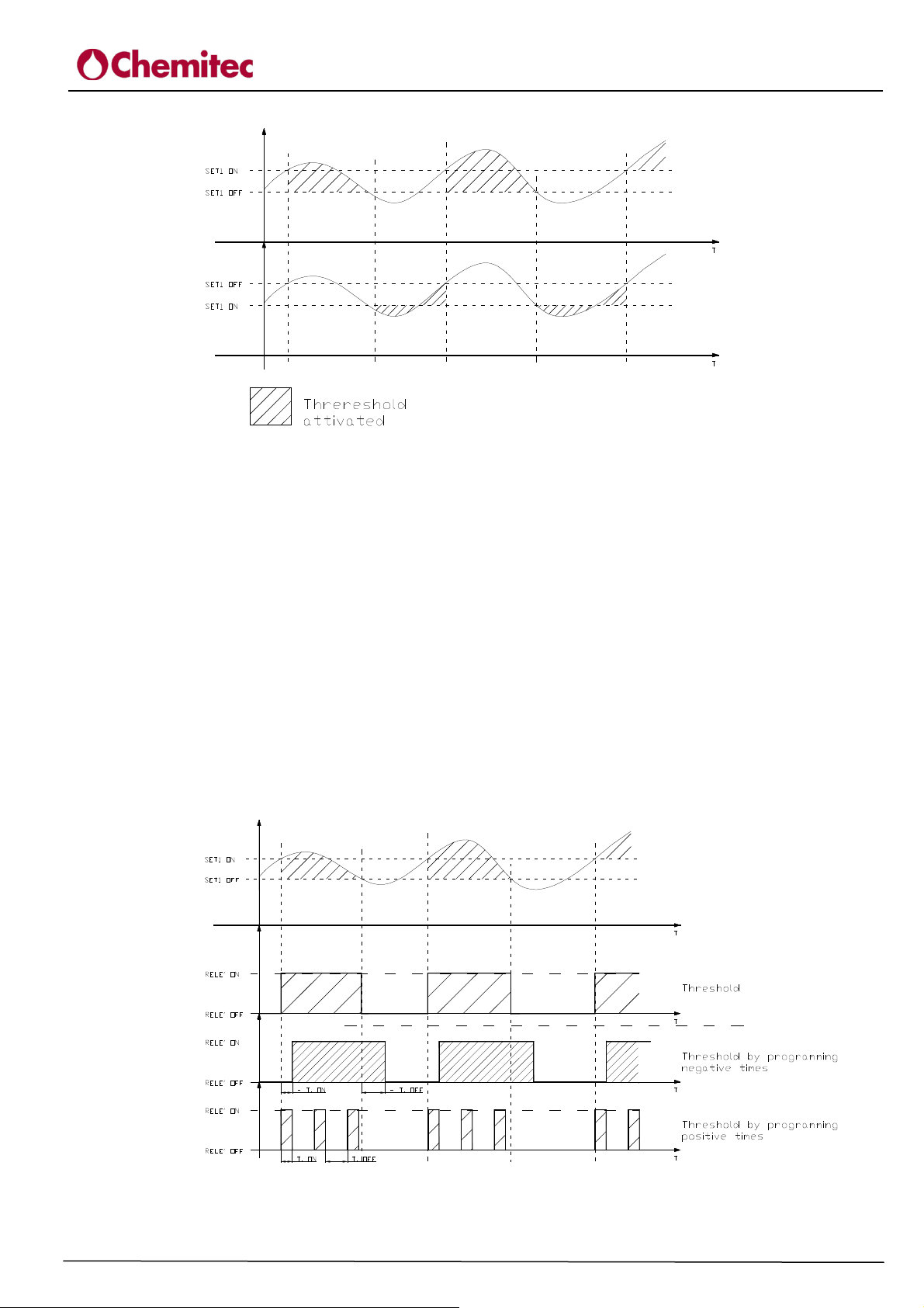
E1) Threshold
By programming the Set Point for this function, we can activate the relay as a Threshold by
programming an ON value (relay activation) and an OFF value (relay deactivation). The free
programming of these two values will allow for the creation of a hysteresis suitable for any kind of
application.
By programming the ON value higher than the OFF one (fig. 15.a) an UPWARD threshold will be
achieved: (When the value exceeds the ON value, the relay is activated and remains active until the
value falls below the OFF value).
By programming the OFF value higher than the ON one (fig. 15.b) a DOWNWARD threshold will
be achieved: (When the value falls below the ON value, the relay is activated and remains active
until the value exceeds the OFF value). See fig.15.
28
Page 33
CONDUCTIVITY AND TEMPERATURE ANALYZER
4222
TECHNICAL MANUAL P/N XXX-0000 Rev.1 Ver.2.2
Measure
a)
b)
Figure 15 – Threshold operation
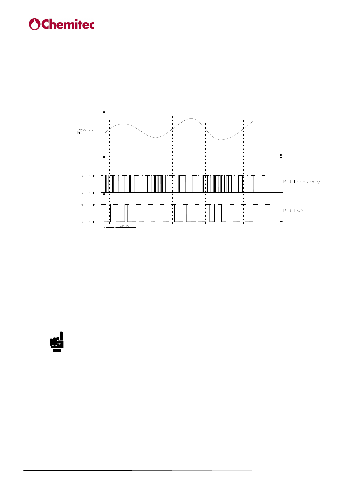
Furthermore by acting on the Time ON and Time OFF parameters it is possible to define a DELAY
time or a TIMED operation of the Relay during its activation.
Negative of positive ON and OFF Times can be defined. (fig. 16)
By programming Negative Times the DELAY function is activated:
Eg. Time ON: –5sec , Time OFF -10sec. (fig. 16.a)
When the threshold is activated, the relay will close after 5 seconds (ON time) and it will remain
closet for the entire period in which the threshold is active. When the threshold is deactivated the
relay will remain closed for another 10 seconds (OFF time) after which time it will open.
By programming Positive Times the TIME function will be activated:
Eg. Time ON: 5sec , Time OFF 10sec. (fig. 16.b)
When the threshold is activated the relay will alternate between an open/closed position according
to the times programmed. In the case of the example the relay will close for 5 seconds (ON time)
after which time it will remain open for 10sec (OFF time). This cycle will continue until Threshold
1 is not deactivated.
Measure
a)
b)
Figure 16 – Operation of Relay 1
29
Page 34
CONDUCTIVITY AND TEMPERATURE ANALYZER
TECHNICAL MANUAL P/N XXX-0000 Rev.1 Ver.2.2
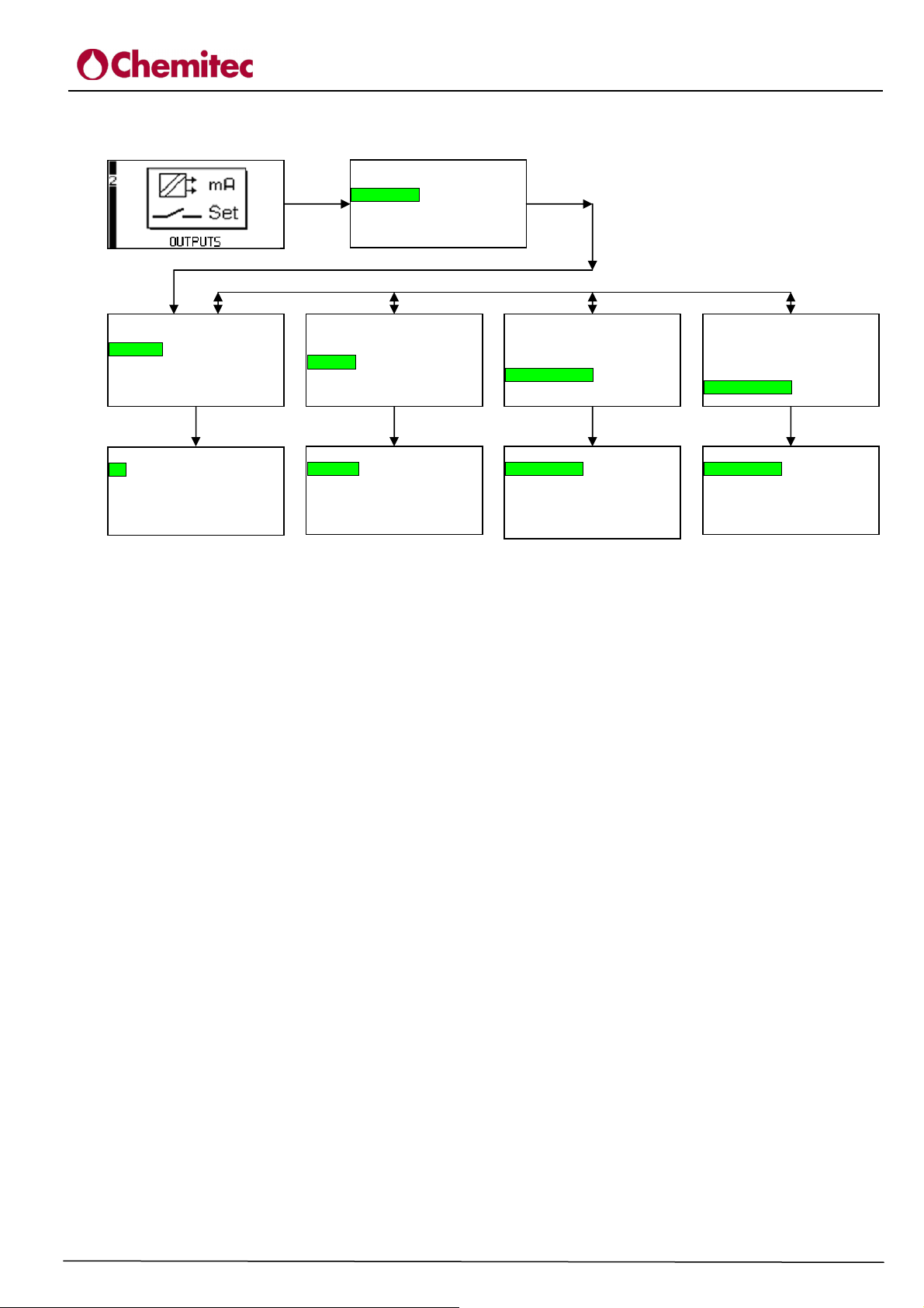
E2) PID-PWM
By defining the Set Point as PID-PWM, through Relay 1, it is possible to activate a pump with an
ON/OFF command almost as if it had a proportional adjustment. For this function the time period
must be programmed (in seconds) within which the calculation of the PWM adjustment will come
about. The maximum time that can be programmed is 999 seconds with a 1 second step. We
recommend starting with short periods of time and increasing them gradually in order to avoid
drastic variations in measuring. For operation of the Relay in a PID-PWM function see fig. 17.b.
Measure
a)
4222
b)
E3) PID-Frequency
By setting the Set Point as PID-Frequency it is possible, through Relay 1, to control a pump directly
with impulse inputs. The maximum number is 7200 imp/h with steps of 200. The ON and OFF
impulse time is fixed at 250mSec. For operation of the Relay in a PID-Frequency see fig. 17.a.
Figure 17 – Operation of Relay 1 as PID
NOTE
Functions E2) and E3) are related to the programming of the PID parameters to be found in
the menu 2.31 (Par. 4.3.8). Therefore, before programming this function we recommend that
you check the programming of the PID parameters.
30
Page 35
CONDUCTIVITY AND TEMPERATURE ANALYZER
Alarm
Set Point Temp.
Alarm
Set Point Temp.
Alarm
Set Point Temp.
Set Point Temp.
Permanen. Time
00:00:00
TECHNICAL MANUAL P/N XXX-0000 Rev.1 Ver.2.2
4.3.5 OUTPUTS MENU (RELAY OUTPUTS – SET POINT 2, ETC.)
2.0 OUTPUT
ENTER
+
DOWN
B1) Set Point2
ENTER
Relay Outputs
Current Output
Setup PID
(F1)
2.1 RELAY OUTPUTS
Set Point 1
Set Point 2
Logic. Set
/Set Temp 1
Wash/Set Temp 2
UP/DOWN
(F2)
2.1 RELAY OUTPUTS
Set Point 1
Set Point 2
Logic. Set
/Set Temp 1
Wash/Set Temp 2
UP/DOWN
(F3)
2.1 RELAY OUTPUTS
Set Point 1
Set Point 2
Logic. Set
Alarm/Set Temp 1
Wash/Set Temp 2
UP/DOWN
ENTER
2.12 SET POINT 2
ON 0.0 mS
OFF 0.0 mS
ON Time +000 Sec
OFF Time +000 Sec
ENTER
2.13 LOGIC SET
Max Value 20.0 mS
Min Value 0.0 mS
ENTER
2.14 ALARM/SET TEMP 1
Relay Abilitation YES
Set Release YES
Relay Logic CLOSED
Time Out 00:00:00
Perman.Field 0.0mS
4222
(F4)
2.1 RELAY OUTPUTS
Set Point 1
Set Point 2
Set Logico
/Set Temp 1
Wash/Set Temp 2
ENTER
2.15 WASH/SET TEMP 2
Relay Abilitation YES
Interval >>>
Duration >>>
Stabilization >>>
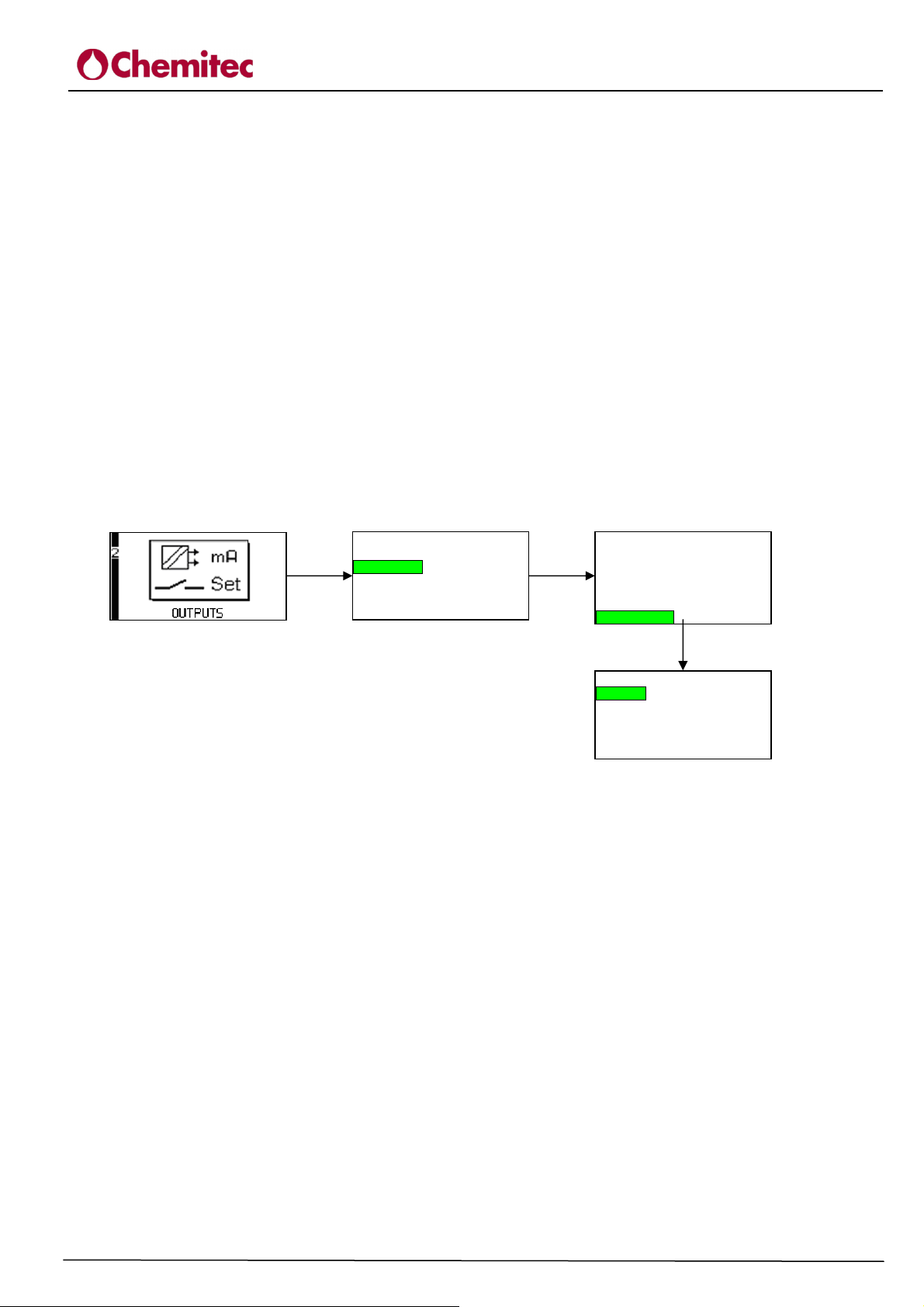
F1) Set Point2
The programming parameters of Set Point 2 determine the functioning logic of Relay 2.
This Relay may only be programmed as a Threshold. Programming of threshold 2 is identical to the
one described for Threshold 1.
F2) Logical Set
The parameters of the Logical Set determine the functioning of the Alarm Relay. This function is
deactivated by default.
This function activates an alarm when the measuring values are located outside of a specific
“window”. It is, in reality, possible to programme a minimum value and a maximum value and
once they are exceeded the instrument will generate an alarm. This function will allow an alarm to
be activated if the measure values are over a certain “range”. In fact, it is possible to program a
minimum and a maximum value: when exceeded, the equipment will generate an alarm.
This Logical Set is useful to control any possible faults to the system, eg. Defects in the dosage
pumps etc.
F3) Alarm/Set Temp. 1
With this function the basic settings of the Alarm Relay are defined, all of which are handled by the
anomaly conditions inside and outside of the instrument.
Considering the importance of this Relay, we recommend that it is connected to a visual and
acoustic signal which should always be kept under control by personnel in charge of running the
plant, in order to intervene immediately in the case of a signal.
Programming of the Alarm Relay is articulated into 6 functions, therefore allowing for external
anomalies (measuring electrode and dosage systems) as well as internal anomalies to be kept under
control. Description of the functions:
RELAY ABILITATION
Within this function, it is possibile to assign the relay.
Setting “YES” means that the relay works as an alarm. Setting “NO”, the relay is automatically
assigned as temperature.
31
Page 36

CONDUCTIVITY AND TEMPERATURE ANALYZER
4222
TECHNICAL MANUAL P/N XXX-0000 Rev.1 Ver.2.2
SET RELEASE
With this function it is possible to deactivate or activate dosages in the case of an alarm.
By programming YES, when any kind of alarm is activated, the Relay 1 and 2 contacts will open up
immediately and the analogical outlets 1 and 2 will be cancelled.
By programming NO, even in the case of activation of the alarm, the Relay contacts and the
analogical outlets will not change their position.
YES is set as a default.
RELAY LOGICS
The Alarm relay is an ON/OFF alarm and with this function it is possible to programme its
opening/closing logic. CLOSED is set as a default.
By setting “CLOSED”, the Alarm relay will be opened in normal working conditions and will close
in the event of an alarm.
By setting “OPEN” it will work in exactly the opposite way. The Alarm relay will close in normal
working conditions and will open in the event of an alarm.
Furthermore, by setting OPEN it is also possible to control the anomaly of the absence of power
tension which will lead to the immediate opening of the relay.
TIME OUT
With this function it is possible to set a maximum activation time of Set Point 1 and 2 after which
time the alarm will be activated. This allows for the state of the dosage pumps to be kept under
control.
By default this function is deactivated (time 00:00.00). The maximum time that can be programmed
is 60 minutes, at steps of 15 seconds.
PERMANENCE FIELD – PERMANENCE TIME
This function allows for the state of functioning of the measuring probe to be kept under control.
If the measurement is stabilised within a certain interval for a period of time that exceeds the time
set, the instrument will generate an alarm.
In order to activate this function, the following must be set:
in the “PERMANENCE FIELD” step the minimum oscillation interval of measuring (delta
CONDUCTIVITY)
in the “PERMANENCE TIME” the maximum time in which excursion must come about.
If, during the period of time programmed, measuring is always within the interval programmed, the
instrument will set off an alarm.
By default this function is deactivated as a delta 0 and a time of 00:00:00 has been programmed.
The maximum time that can be programmed is 99 hours at steps of 15 minutes.
F4) Wash/Set Temp. 2
The instrument is fitted with a Washing Relay that can control a solenoid valve for washing of the
measuring electrode.
The washing stage lasts 1 minute altogether and it includes 15 seconds for control of the solenoid
valve (closing of the washing relay) and 45 seconds for stabilisation of the probe.
RELAY ABILITATION
Within this function, it is possibile to assign the relay.
Setting “YES” means that the relay works as wash. Setting “NO”, the relay is automatically
assigned as temperature.
32
Page 37
INTERVAL
Alarm
Set Point Temp.
With this function it is possible to set the interval of time between one washing stage and the next.
Immediately before it starts, the instrument memorizes the values of the measurements, the state of
Relay 1 and 2 and the values of the analogical outlets and it keeps them “frozen” for the entire
duration of the washing cycle.
This situation is highlighted on the display using an hourglass and, furthermore, instead of the
measuring value a counter appears indicating how many seconds are left until the washing stage is
completed.
By default this function is deactivated as a time of 00 hours and 00 minutes is programmed. The
maximum interval that can be programmed is 24 hours at steps of 15 minutes.
DURATION
Within this function it is possibile to set the duration (in seconds) of the washing period.
STABILIZATION
Within this function it is possibile to set the time (in seconds) needed to the stabilize the wash.
4.3.6 OUTPUTS MENU (SET POINT TEMP.)
ENTER
Relay Outputs
Current Output
Setup PID
2.0 OUTPUT
G1) Set Point Temp.
If at least one of the two relays in points F3), F4) is set as temperature relay, within this step it is
possibile to set up the Set Point.
ENTER
+
DOWN
CONDUCTIVITY AND TEMPERATURE ANALYZER
TECHNICAL MANUAL P/N XXX-0000 Rev.1 Ver.2.2
(G1)
2.1 RELAY OUTPUT
Set Point 1
Set Point 2
Logic. Set
/Set Temp 1
Wash/Set Temp 2
ENTER
2.16 SET POINT TEMP.
SET 1 ON +000 °C
SET 1 OFF +001 °C
SET 2 ON +000 °C
SET 2 OFF +001 °C
4222
33
Page 38
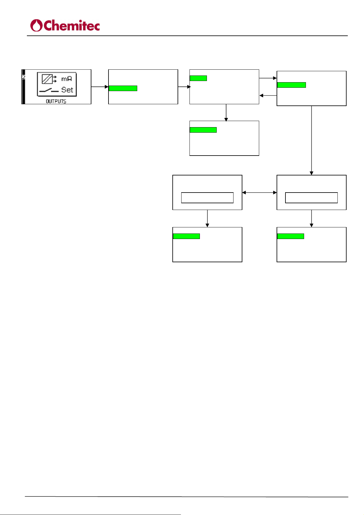
4.3.7 OUTPUTS MENU (CURRENT OUTPUT)
ENTER
+
DOWN
Relay Outputs
Current Output
Setup PID
2.0 USCITA
ENTER
(H1)
2.2 CURRENT OUTPUT
Measure
Second Output
ENTER
CONDUCTIVITY AND TEMPERATURE ANALYZER
TECHNICAL MANUAL P/N XXX-0000 Rev.1 Ver.2.2
(H2)
4222
UP
2.2 CURRENT OUTPUT
Measure
Second Output
DOWN
ENTER
2.21 MEASURE
Output Range 0-20 mA
Low Limit 0.0 mS
High Limit 20.0 mS
Namur Output NO
2.2 CURRENT OUTPUT
Second Output
Auxiliary
ENTER
UP/DOWN
2.2 CURRENT OUTPUT
Seconda Uscita
Temp
ENTER
2.22 AUXILIARY
Output Range 0-20 mA
Low Limit 0.0 mS
High Limit 20.0 mS
PID NO
2.22 TEMPERATURE
Output Range 0-20 mA
Low Limit -030°C
High Limit +140°C
PID NO
The instrument is fitted with two analogical outlets in a current that is separated galvanically and are
independent of each other. The first outlet refers to the primary measuring therefore proportional to
the Conductivity measured. The second, however, can be programmed between Temperature or
CONDUCTIVITY.
H1) Measuring
In this step of the programme 4 functions can be set:
OUTPUT RANGE:
A selection can be made between 0-20mA or 4-20mA. The default is programmed at 0-20mA
LOWER LIMIT:
A Conductivity value at 0 to 4mA of output current can be set. The default is set at 0mS
UPPER LIMIT:
A Conductivity value of 20mA can be set for output current. The default is set at 20.0mS.
The regulation of Lower and Upper Limit functions allow for the scale of analogical outputs to be
amplified. Furthermore, the output can be inverted to 20-0mA o 20-4mA
NAMUR OUTPUT:
This function is only activated if chosen as an Outlet Range of 4-20mA. If this function is activated
in the case of an alarm, the outward value of the current will be 2.4mA according to the NAMUR
standard. The default of this function is deactivated.
H2) Second Output
34
Page 39
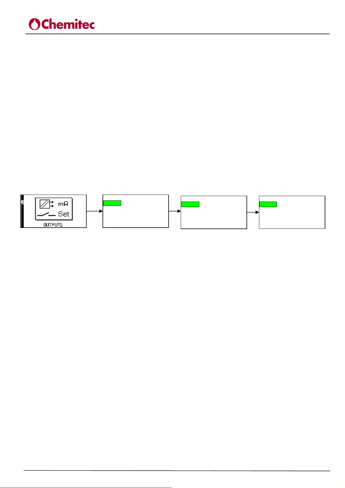
The second output can be set as Temperature, Auxiliary or PID.
Algor.
If set as Temperature a Range between 0-20mA or 4-20mA can be chosen, the Lower and Upper
limits of the Temperature value. For a detailed description of how to set them, refer to point 5.1
Measuring of Analogical Outlet. The default Range is 0-20mA, the Lower Limit is –30°C and the
Upper Limit is +140°C.
If set as Auxiliary on the second output also, the conductivity measurement is repeated. But the
Range of between 0-20mA or 4-20mA, the Lower limit and the Upper limit of the conductivity
values can be chosen, different to the previous ones. For a detailed description of how to set them
refer to point 5.1 Measuring of Analogical Outlet. The default Range is 0-20mA, the Lower Limit
is 0mS and Upper Limit is 20.0mS.
If set as PID the Output range of between 0-20mA or 4-20mA must be set. For settings of the PID
see part C3.
4.3.8 OUTPUTS MENU (SETUP PID)
2.30 SETUP PID
Set Point 6.9 mS
Param. PID >>>>
ENTER
+
DOWN
(I1)
2.30 SETUP PID
Set Point 6.94 mS
PID Param. >>>>
CONDUCTIVITY AND TEMPERATURE ANALYZER
4222
TECHNICAL MANUAL P/N XXX-0000 Rev.1 Ver.2.2
2.31 PID PARAMETERS
Algorithm P
Sign Direct
Proport.Rate. 100 %
riv. . Time 00:00:00
DOWN
Integral Time 00:00:00
+
ENTER
I1) Setup PID
In this step of the programme, the programming of parameters for PID functioning is carried out.
The outlet of PID adjustment is analogical as well as digital and they can both be activated at the
same time. The PID outlets are: Analogical Outlet 2 and Relay 1.
The PID function allows for all of the swings due to ON/OFF dosages to be eliminated.
Furthermore, it allows for the threshold desired to be maintained and reached with extreme
precision. The PID adjustment is a complicated adjustment that must take into account all system
variables. This PID has been designed for those general applications with a fast retroactivity of the
system. In reality, the maximum integral and derived times are 5 minutes.
The PID function allows for three adjustments to handle the dose.
The PROPORTIONAL (P) Adjustment allows for the outward dimension to be more or less
amplified.
The DERIVATIVE (D) function allows for our system to become more or less reactive to variations
of the sizes measured.
The INTEGRATIVE (I) function allows for the swings to be regulated due to the derivative part.
Description of functions:
SET POINT
The value of the PID threshold that we want to maintain stable.
PID SETUP
ALGORITHM
The kinds of algorithms handled by the instrument are: P = Proportional ; PI = Proportional –
Integral and PID = Proportional – Integral – Derivative
35
Page 40

CONDUCTIVITY AND TEMPERATURE ANALYZER
4222
TECHNICAL MANUAL P/N XXX-0000 Rev.1 Ver.2.2
The type of algorithm will be chosen according to the application requested. The P regulation
will be set as a default.
THE ALGORITHM SIGN
In this function the PID sign is programmed. If we programme DIRECT it means that as the
value measured is increased compared with the threshold defined, the PID value will decrease.
However, if we programme OPPOSITE, as the value measured increases compared with the
threshold defined, the PID value will increase. DIRECT is set as a default.
PROPORTIONAL
The Proportional Range of the PID regulation compared with the bottom of the scale for the
instrument.
Eg. For a conductivity with a range of 0-20mS, if a 100% Proportional is programmed it
means having a range of ±20mS of regulation compared with the threshold set. Therefore the
value of the proportional is inversely proportional to the outlet, that is to say as the percentage
of the proportional is increase the effects on the outlet decrease. Regulation of the proportional
may vary between 1 and 500% in steps of 1%. The default is set at 100%.
DERIVATIVE TIME
The Derivative part is set. The more the programmed time increases, the more the system will
be ready for variations to the measurement. The derivative time can be programmed between 0
and 5 minutes at steps of 5 seconds. The default is programmed at 0 minutes.
INTEGRAL TIME
The Integrative part is set. The more the programmed time increases, the more the system will
mediate with the measuring swings. The derivative time can be programmed between 0 and 5
minutes at steps of 5 seconds. The default is programmed at 1 minute.
4.3.9 CALIBRATIONS MENU
This programme phase allows for the instrument calibration with the electrode used. Calibration
must be carried out:
− When starting the measure instrument / electrode chain the first time
− Every time the electrode is replaced
− When starting the instrument after a long inactivity period
− In the case of any discrepancies compared with the known value
For granting a proper working, further to the above mentioned conditions, it will be required to
check the calibration of or to recalibrate the instrument periodically.
User will determine the frequency of this operation, keeping into account the application and the
electrode use.
We remind you that before carrying out any checks or recalibrations, the electrode must be cleaned
thoroughly with clean water, making it stabilizing for at least 30 minutes on the atmosphere or into
the known title solution.
NOTE
36
Page 41
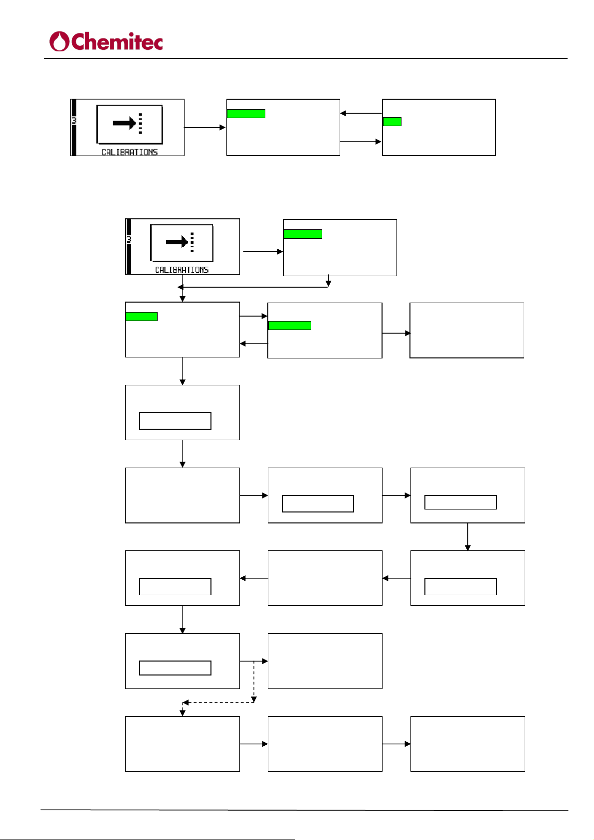
Descriptions of the calibration functions:
Automatic
Are you sure
Press ENTER
Value
Press ENTER
Value:
Are you sure?
ENTER
ENTER
From this menu it is possible to choose the type of calibration: Conductivity or Temperature
4.3.9.1 Conductivity calibration
ENTER
(J1)
3.1 CALIBRATIONS COND
Automatic
Default Reset
ENTER
(J1.1)
3.1 CALIBRATIONS COND
First Calibration
Temperature
+026°C
3.0 CALIBRATIONS
Conductivity
Temp
+
DOWN
(J2)
UP
DOWN
3.1 CALIBRATIONS COND
Default Reset
3.0 CALIBRATIONS
Conductivity
Temp
UP
DOWN
ENTER
CONDUCTIVITY AND TEMPERATURE ANALYZER
TECHNICAL MANUAL P/N XXX-0000 Rev.1 Ver.2.2
3.0 CALIBRATIONS
Conductivity
Temp
3.1 CALIBRATIONS COND
Default Reset
ENTER
Default Values
?
4222
ENTER
ENTER
ENTER
(J1.3)
3.1 CALIBRATIONS COND
First Calibration
00.00 µS
ENTER
3.1 CALIBRATIONS COND
Second Calibration
Temperature
+026°C
3.1 CALIBRATIONS COND
First Calibration
Insert Probe
Press ENTER
(J1.4)
3.1 CALIBRATIONS COND
Second Calibration
Wait Stabilization
08.98 µS
ENTER
ENTER
ENTER
(J1.2)
3.1 CALIBRATIONS COND
First Calibration
Wait Stabilization
00.10 µS
3.1 CALIBRATIONS COND
Second Calibration
Insert Probe
Press ENTER
(J1.5)
3.1 CALIBRATIONS COND
Second Calibration
10.00 µS
IF THE PROBE IS FAULTY
3.1 CALIBRATIONS COND
Second Calibration
Faulty Probe
Press ENTER
ENTER
ENTER
3.1 CALIBRATIONS COND
Calibration OK
Press ENTER
3.1 CALIBRATIONS COND
Second Calibration
Reset Default
Press ENTER
ENTER
3.1 CALIBRATIONS COND
Second Calibration
Default Values
37
Page 42
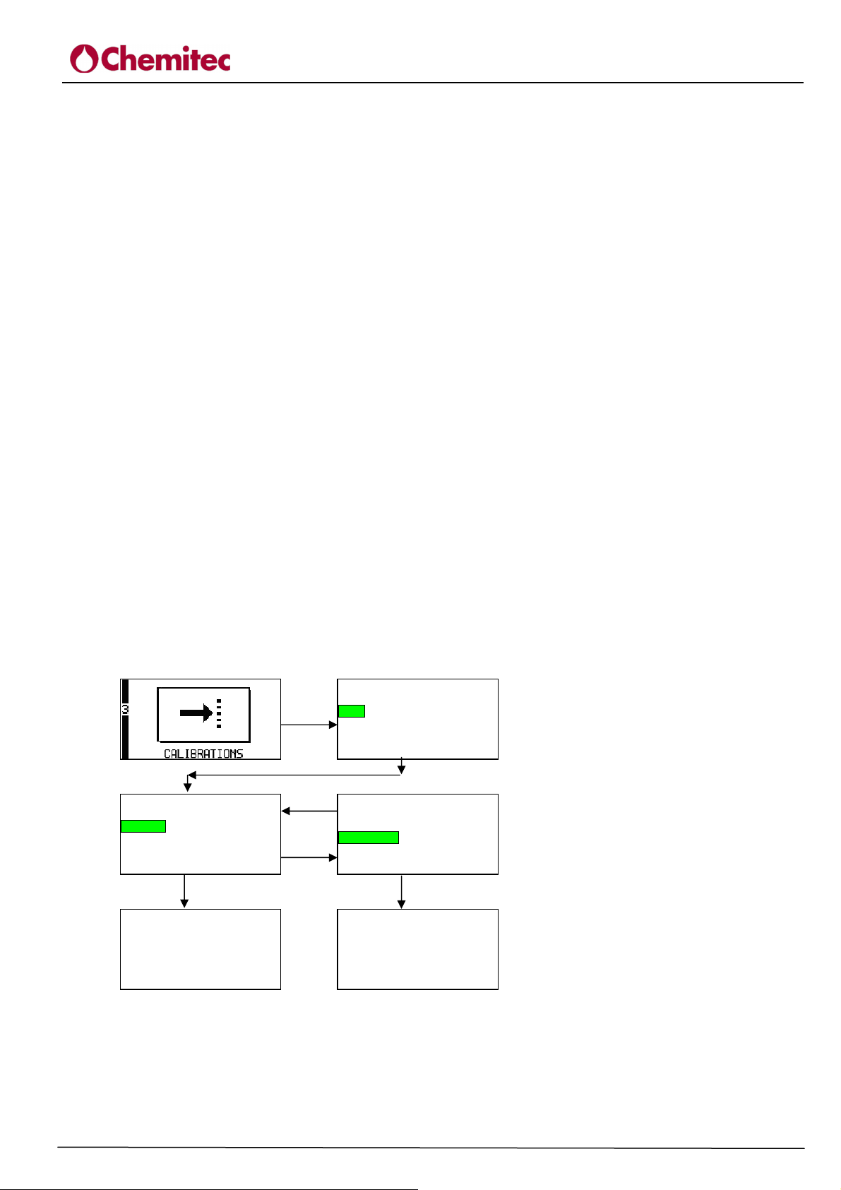
CONDUCTIVITY AND TEMPERATURE ANALYZER
Automatic
Are you sure?
(K2)
(K1)
ENTER
4222
TECHNICAL MANUAL P/N XXX-0000 Rev.1 Ver.2.2
J1) Automatic system
The conductivity calibration foresees two calibration points.
J.1.1) The first calibration must be done at 0µS !! After inputting the temperature compensation
value (if the conductivity probe is temperature compensated, the temperature value will be read
automatically) press ENTER key and dip the probe into a solution at 0µ S or expose it to air after
proper drying. Press ENTER.
J.1.2) Wait for the displayed value, read by the probe, to stabilize, then press ENTER.
J.1.3) The instrument will display the 0000µS value automatically. Press ENTER.
J.1.4) and J.1.5) Calibrate the second point as per the first one. On this step, solutions with
known title and different concentrations can be used and inserted by pressing the UP and DOWN
keys.
The calibration solution can be selected referring to the working range where the probe will
work in. Example: If the working range is between 500 and 1000µS, use a solution at approx.
750-800µS as second point.
Once finished the second point calibration, the instrument will check the calibration data
compliance. If correct, the instrument will display “Calibration OK”; if not “Faulty probe”.
If ”Faulty Probe” is displayed, we recommend:
− To check the physical probe integrity.
− To check the cable integrity, the correct connection to the instrument and on the probe.
J2) Default Reset
This step of the programme allows for the calibration factors to be reset to the original factory ones.
To be used when incorrect calibrations are confirmed.
4.3.9.2 Temperature calibration
+
DOWN
3.3 TEMP CALIBRATION
Automatic
Default Reset
NTC CALIBRATION
Temp. Offset
+00.0 °C
T= +25.0 °C
ENTER
UP
DOWN
The calibration of Temperature allows to align the values given by the temperature sensor to the real
analisys values; this step must be done only if the operator finds a few differences between the
values given by the instrument and the real temperature.
3.0 CALIBRATIONS
Conductivity
Temp
ENTER
3.3 TEMP CALIBRATION
Default Reset
ENTER
3.3 TEMP CALIBRATION
Default Reset
Default Values
38
Page 43
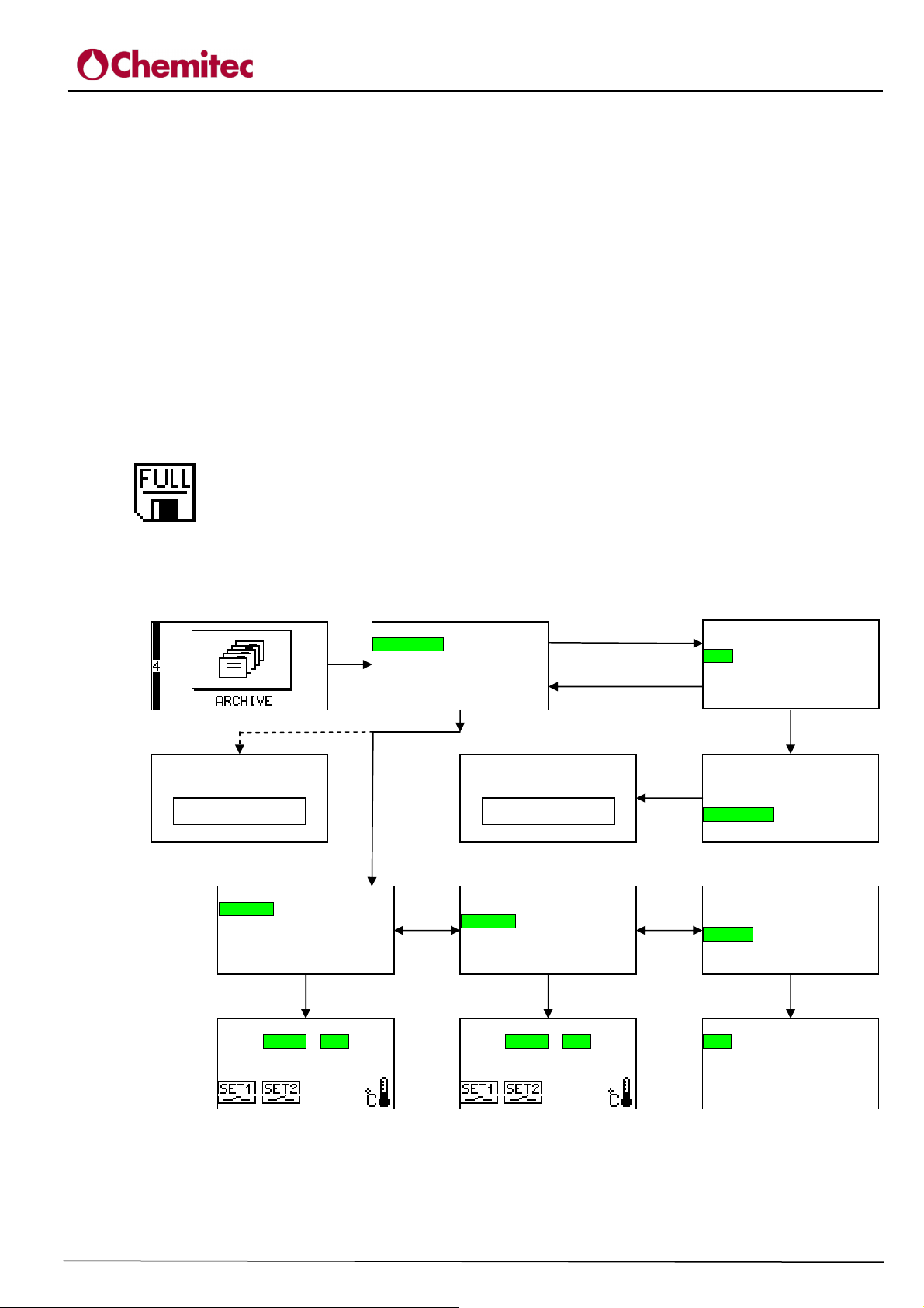
K1) Automatic Calibration
Archive
UP
The calibration consists in adding or subtracting an offset in order to bring back the value given by
the instrument to the correct measure.
K2) Reset Default
As shown in J2) step, this step of the programme allows for the calibration factors to be reset to the
original factory ones..
4.3.10 ARCHIVE MENU
The instrument is fitted with a Data Logger that allows for 16,000 records to be stored. Each record
contains: the date, the time and the Conductivity value, the temperature value, the value of the
Threshold 1 and 2, the state of the Relays 1 and 2 and the state of the Alarm Relay. The archive
must be of a Circular kind, therefore once filled the next data will overwrite the oldest one and so
on until it is completely FILLED, that is to say once it is filled storage is blocked and the full
archive icon will appear.
CONDUCTIVITY AND TEMPERATURE ANALYZER
4222
TECHNICAL MANUAL P/N XXX-0000 Rev.1 Ver.2.2
The archive can be examined directly through the instrument in the form of a table or drawing. The
archive may be downloaded using a RS485 serial port with the MOD BUS RTU protocol.
Empty Archive
ENTER
4.10 SHOW RECORDS
First record >>>>
Last record >>>>
Date/hour >>>>
(L1)
Show Records
Setup
4.0 ARCHIVE
ENTER
Are you sure?
4.10 SHOW RECORDS
First record >>>>
UP
Last record >>>>
DOWN DOWN
Date/hour >>>>
UP
DOWN
ENTER
(L2)
4.0 ARCHIVE
Show Records
Setup
ENTER
4.20 SETUP
Step 1 min
--->
Memory Filli. 3 %
Memory Reset >>>>
4.10 SHOW RECORDS
First record >>>>
Last record >>>>
Date/Hour >>>>
L1) Visualise data
In this part of the programme it is possible to visualise data in the form of a table as long as the archives
are not empty. In order to decide on where to start and examine the table, there are three options:
First Data >>> You will start by examining the archive of the first data stored and move forward
ENTER
4.10 SHOW RECORDS
21/04/05
6.8 mS
+027
14:38
ENTER
4.10 SHOW RECORDS
26/04/05
14:38
6.8 mS
+028
ENTER
4. DATE/HOUR
Show >>>>
Date >>>>
Hour >>>>
39
Page 44
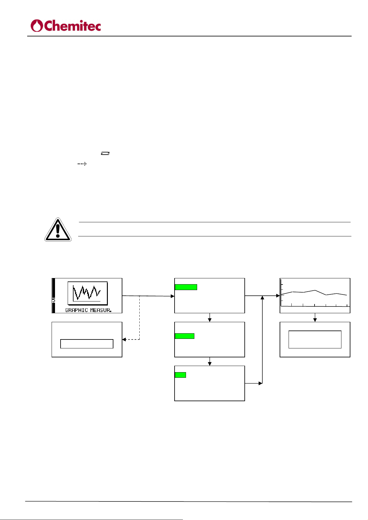
CONDUCTIVITY AND TEMPERATURE ANALYZER
TECHNICAL MANUAL P/N XXX-0000 Rev.1 Ver.2.2
Last Data >>> You will start by examining the archive of the last data stored and move backwards
Date/Time>>> You will start by examining the archive from a specific date and time
In order to move backwards and forwards use the UP and DOWN keys and once you reach the first
or last data it will stop.
L2) Set-up
In this part of the programme the storage parameters are set using 4 functions:
STEP
It indicates the registration step and it can be programmed at between 0 and 99 minutes. The default
is 0 minutes, therefore deactivated, and it can be increased by 1 minute at a time.
ARCHIVE TYPE
Circulation of “ “of the Archive once it is full and it will write over the first data
Filling “ ” Once it is full it will stop storage
SPACE USED
It indicates the amount of memory used up by the data stored.
MEMORY RE-SET
It is used to clean the memory.
CAUTION
Once this operation is carried out all measurements stored will be lost.
4222
4.3.11 MEASURING GRAPHICS MENU
ENTER
Empty Archive
In this step of the programme you can see data in a graphic form, as long as the archive is not
empty. In order to decide from where to start to examine the graphics and tables, there are two
options:
First Data >>> You will start by examining the archive of the first data stored and move forward
Date/Time>>> You will start by examining the archive from a specific date and time
In order to move backwards and forwards use the UP and DOWN keys and once you reach the first
or last data it will stop.
5.0 GRAPHIC MEASUR
First record >>>>
Date/hour >>>>
Time setting 1h
DOWN
5.0 GRAPHIC MEASUR
First record >>>>
Date/hour >>>>
Time setting 1h
ENTER
5.20 DATE/HOUR
Show >>>>
Date 26/04/05
Hour 14:45
ENTER
ENTER
20.00
14:38 26/04/05 15:38
ENTER
Maximum 10.8
Minimum 10.7
Mean 10.5
40
Page 45
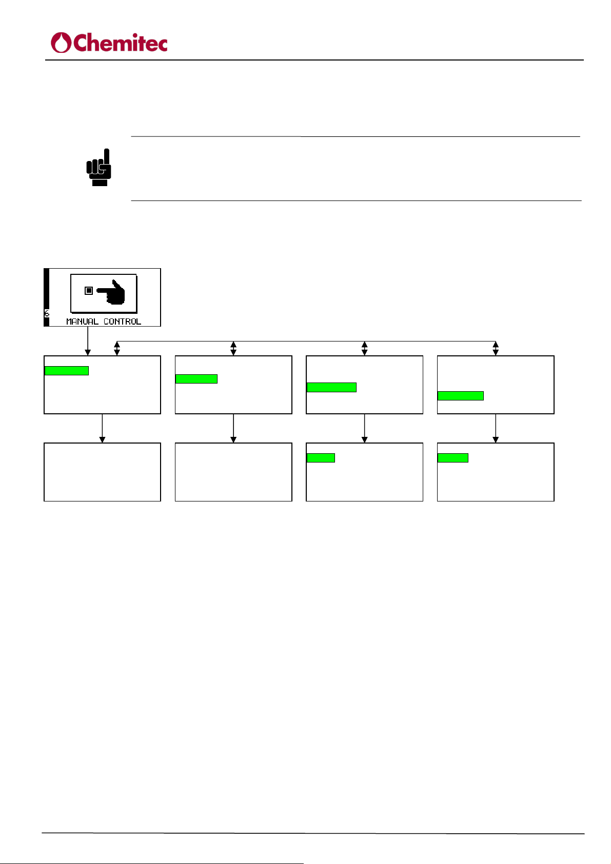
The Times item indicates for how many hours we want to visualise the drawing. The default
Analog Outputs
Analog Inputs
Analog Inputs
Analog Outputs
Analog Inputs
Analog Outputs
Analog Inputs
Alarm
is 1 hour but we can choose from 1, 6 or 24 hours.
Once the drawing is visualised, if the ENTER key is pressed a table will appear indicating
the Minimum, Maximum and Average value of the measurements visualised on the screen.
Furthermore, if the ENTER key is pressed again, a ZOOM of the data visualised will appear.
If the ENTER key is pressed again, it will return to the initial visualisation.
The ZOOM allows for a clearer evaluation of small Conductivity variation..
4.3.12 MANUAL CONTROL MENU
NOTE
CONDUCTIVITY AND TEMPERATURE ANALYZER
4222
TECHNICAL MANUAL P/N XXX-0000 Rev.1 Ver.2.2
ENTER
(M1)
6.0 MANUAL CONTROL
Analog Inputs
Digital Inputs
Relay Outputs
ENTER
6.1 MANUAL CONTROL
M.. Channel: 2077
M.. Channel: 0399
UP/DOWN
This step of the programme is useful for all functional controls eg. Upon installation to check
functioning of the entire system.
M1) Analogical Inputs
This function allows for the values read by the digital analogical converter related to the
Conductivity and temperature measuring to be seen directly.
This allows you to understand if the level of analogical acquisition of the instrument works
correctly.
(M2)
6.0 MANUAL CONTROL
Digital Inputs
Relay Outputs
ENTER
6.2 MANUAL CONTROL
Digital Inputs
Digital Input: OFF
UP/DOWN
(M3)
6.0 MANUAL CONTROL
Digital Inputs
Analog Outputs
Relay Outputs
6.30 ANALOG OUTPUTS
Output 1 0.0
Output 2 0.0
ENTER
UP/DOWN
(M4)
6.0 MANUAL CONTROL
Digital Inputs
Relay Outputs
6.40 RELAY OUTPUTS
RELAY 1 OFF
RELAY 2 OFF
OFF
Wash OFF
ENTER
M2) Digital Inputs
The instrument is fitted with a passive digital input, separated galvanically, which allows for the
doses to be deactivated, on the Relay and also on the Analogical Outlets. This step allows you to
check whether or not the digital input of dosage deactivation works correctly. If it is Open it must
indicate OFF and if, however, tension is applied to the clamps, according to specifications, the
instrument should indicate ON.
M3) Analogical Outputs
It allows for manual simulation of both the Analogical Outputs under current. The variations of the
outputs have a pass of 0.1mA.
M4) Relay Outputs
It allows for manual activation of the Relay Outputs
41
Page 46
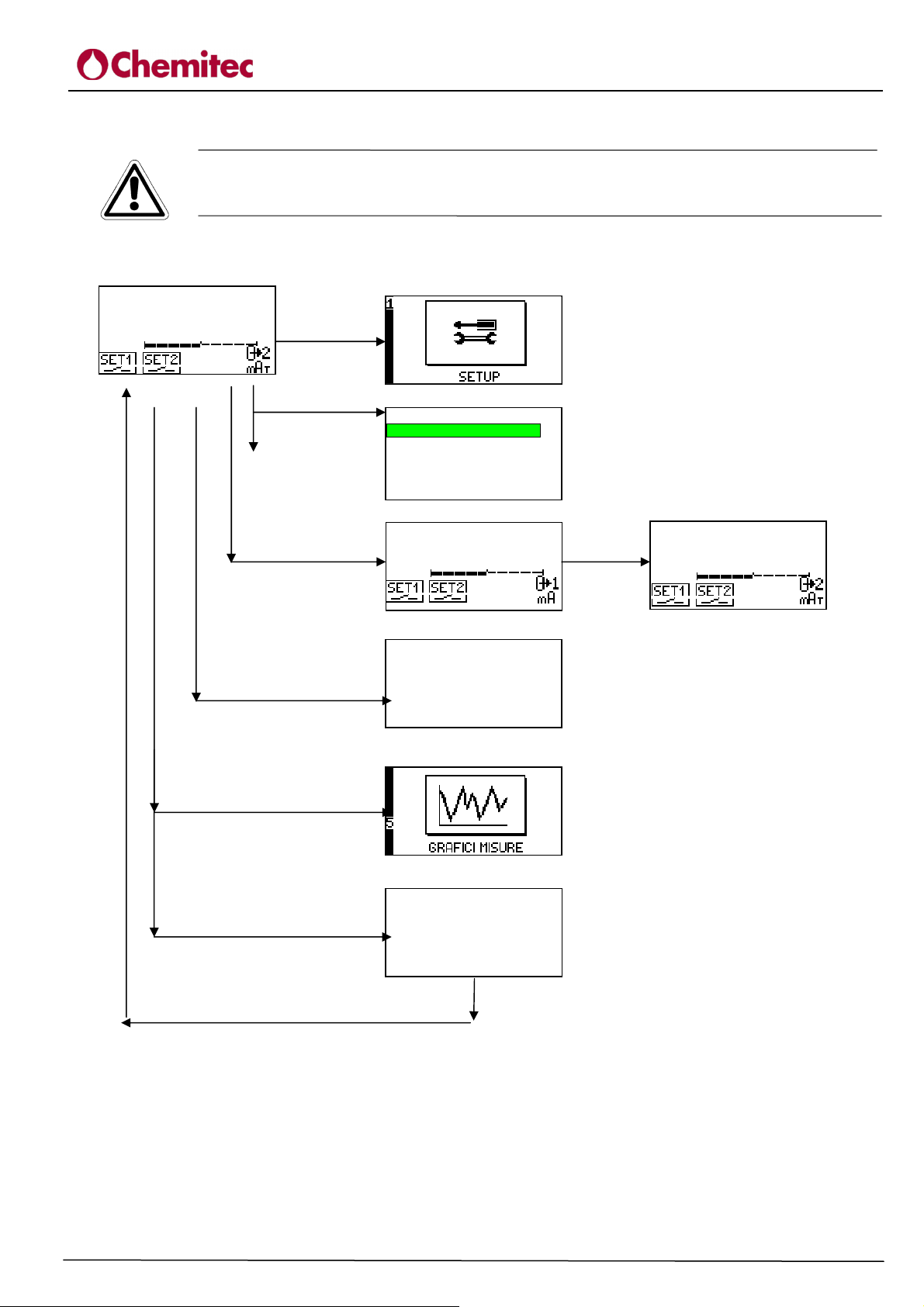
relay Set Point
2
When exiting from the “MANUAL CONTROL” function, all the possible manual settings will
be reset.
4.3.13 FUNCTIONS IN RUN
1.0 mS
6.6
ESC
UP
ENTER
CAUTION
(N1)
(N2)
EDITING RUN
Set Point 1 ON
Set Point 1 OFF
relay Set Point 1
Set Point 2 ON
Set Point 2 OFF
1.0 mS
10.0
(N4)
CONDUCTIVITY AND TEMPERATURE ANALYZER
TECHNICAL MANUAL P/N XXX-0000 Rev.1 Ver.2.2
(N3)
ENTER
1.0 mS
6.6
4222
DOWN
1.0mS
(N5)
GRAPH
GRAPH (HOLD ON)
PENDRIVE BACKUP
ENTER
42
Page 47

CONDUCTIVITY AND TEMPERATURE ANALYZER
TECHNICAL MANUAL P/N XXX-0000 Rev.1 Ver.2.2
In the RUN screen the following things can be seen:
• Dissolved Conductivity measure
• Percent value compared to full scale (bargraph)
• the status and type of programming of Relays 1 and 2
• Status of Digital Input
• Status of the Alarm Relay
• Status of the Washing Relay
• Status of the Password
• Status of measuring and outlet freezing
• Value of the Temperature or of the Analogical Outlet 1 or of the Analogical Outlet 2
• System errors
• Storage of Data in the Archive
• Archive Full
N1) Pressing the ESC key
By pressing this key you will enter the Instrument Programming stage and all measuring and dosage
functions will be deactivated. Caution: the instrument will not leave this stage automatically and
therefore if it is left in the Instrument Set-up it will never carry out any operation.
In the Instrument Set-up stage, serial communication is also deactivated.
4222
N2) The UP key
It visualises the status and the value of the Set Point 1 and 2 without blocking the operation of the
instrument or stopping the pump.
N3) The ENTER key
It visualises the value of Temperature of the value of the Analogical outlet 1 or the value of the
Analogical outlet 2 at the bottom of the display.
N4) The DOWN key
It is possible to ZOOM on the primary measure.
N5) The GRAPH key
It is possibile to visualise directly the GRAPHIC MEASURE menu.
OPTIONAL: Holding the GRAPH key for 3-4 seconds during the run functions
It visualises the PENDRIVE BACK UP menu (Optional), through which it is possible to download
data on an USB stick (ONLY FOR WALL MOUNTING VERSION).
43
Page 48

CONDUCTIVITY AND TEMPERATURE ANALYZER
TECHNICAL MANUAL P/N XXX-0000 Rev.1 Ver.2.2
5 USER MAINTENANCE
5.1 SPECIAL CAUTIONS FOR CRITICAL COMPONENTS
An LCD (Liquid Crystal Display) is incorporated into the equipment and it contains small amounts
of toxic materials.
In order to avoid damages to people and to limit the negative effects on the environment, comply
with the following instructions:
Display LCD:
• The LCD display of the electronic device is fragile (it is made of glass) and therefore should be
handled with extreme care. For this reason we recommend that the device is protected in its
original packaging during transport or when not in use.
• If the glass of the LCD breaks and liquid spills out, make sure that you do not touch it. Wash
every part of the body that may have come into contact with the liquid for at least 15 minutes.
If, once this operation has been carried out, you notice any symptoms consult a doctor
immediately.
4222
44
Page 49

CONDUCTIVITY AND TEMPERATURE ANALYZER
TECHNICAL MANUAL P/N XXX-0000 Rev.1 Ver.2.2
6 MODBUS PROTOCOL
Main features
• Protocollo MODBUS standard tipo RTU
• Layer fisico: RS485 a due fili (half-duplex)
• Layer fisico alternativo: USB
• 8 bit, Parità N, 1 Stop bit
• Baud-rate: da 300 a 38400 bps, impostabile da menù
• ID scheda: da 1 a 255, impostabile da menù
Function 01 (Read Coil Status)
00 Stato fisico relay RL0-K1 (Set 1)
01 Stato fisico relay RL1-K2 (Set 2)
02 Stato fisico relay RL2-K5 (Allarme / Set Temp. 1)
03 Stato fisico relay RL3-K6 (Wash / Set Temp. 2)
04 Stato Set Point 1
05 Stato Set Point 2
06 Flag Allarme Time Out Set Point 1
07 Flag Allarme Time Out Set Point 2
08 Flag Allarme Set Logico Min
09 Flag Allarme Set Logico Max
10 Flag per lavaggio o stabilizzazione in corso
Function 02 (Read Input Status)
00 Tipo uscita mA1 (0=0-20 mA, 1=4-20 mA) (out1_typ)
01 Tipo uscita mA2 (0=0-20 mA, 1=4-20 mA) (out2_typ)
02 Uscita Namur (0=Disattiva, 1=Attiva) (namur_flag)
03 Flag per sgancio su allarme (0=sgancio, 1=non sgancio) (alrel_flag)
04 Flag per tipo di Temperatura (0=°C, 1=°F) (fahren_flag)
05 Segno Algoritmo PID (0=Diretta, 1=Inversa) (pid_cnsgn)
06 Logica Relè Allarme in ON (0=Chiuso, 1=Aperto) (alrlog_flag)
07 Funzionamento Analog Out 2 (0=Proporzionale, 1=PID) (pid2_flag)
08 Tipo Archivio (0=Riempimento, 1=Circolare) (reg_typ)
09 Compensazione della temperatura (0=Automatica, 1=Manuale) (tmpc_flag)
10 Tipo strumento (0=Analogico, 1=Digitale) (DigitalProbe)
11 Assegnazione Analog Out 2 (0=Misura principale, 1=Temp)
12 Assegnazione relè RL2 (0=Allarme, 1=Set Point 1 Temperatura)
13 Assegnazione relè RL3 (0=Wash, 1=Set Point 2 Temperatura)
Function 03 (Read Holding Registers)
2 registri consecutivi relativi ai 4 byte che compongono la variabile floating point (ad eccezione
dell’indirizzo 00 che è relativo alla classe dello strumento ed è costituito da 4 caratteri ASCII) .
Dato che ogni valore è su due registri Modbus (4 bytes) e che i valori iniziano su registri di indirizzo
pari, è stato introdotto un controllo che lo Starting Address dei registri richiesti sia pari e che il numero
dei registri richiesti sia anch’esso pari. Altrimenti si ottiene una risposta con errore di indirizzamento.
(se si utilizza il programma Modbus Poll, visualizzare in modalità “Float Inverse”)
00 Classe strumento ('4223') 4 bytes ASCII
02 Matricola strumento (0...65535)
04 Main Value (Conducibilità)
06 Valore della temperatura in °C
08 Valore Uscita analogica1 in mA
10 Valore Uscita analogica2 in mA
12 Set 1 ON (set1_on)
14 Set 1 OFF (set1_off)
16 Set 2 ON (set2_on)
18 Set 2 OFF (set2_off)
20 Set Max (set_max)
4222
45
Page 50

CONDUCTIVITY AND TEMPERATURE ANALYZER
TECHNICAL MANUAL P/N XXX-0000 Rev.1 Ver.2.2
22 Set Min (set_min)
24 Limite basso Analog Out 1 (Misura Principale) (clim1_low)
26 Limite alto Analog Out 1 (Misura Principale) (clim1_high)
28 Limite basso Analog Out 2 (Misura Principale / Temperatura) (clim2_low)
30 Limite alto Analog Out 2 (Misura Principale / Temperatura) (clim2_high)
32 Set Temperatura 1 ON (set1T_on)
34 Set Temperatura 1 OFF (set1T_off)
36 Set Temperatura 2 ON (set2T_on)
38 Set Temperatura 2 OFF (set2T_off)
40 PID: valore soglia (set_pid)
42 PID: range proporzionale (pid_prange)
44 PID: minuti per Derivata (pid_tvmin)
46 PID: secondi per Derivata (step 5 sec) (pid_tvsec)
48 PID: minuti per Integrale (pid_tnmin)
50 PID: secondi per Integrale (step 5 sec) (pid_tnsec)
52 PID: tipo algoritmo PID (0=P, 1=PI, 2=PID)(pid_cntyp)
54 Temperatura di compensazione in manuale (tmp_com)
56 Ore intervallo lavaggio (wash_hour)
58 Minuti intervallo lavaggio (wash_min)
60 Secondi durata lavaggio (wash_lenght)
62 Minuti per allarme temporizzato (alr_min)
64 Secondi per allarme temporizzato (alr_sec)
66 Duty per Set1 ON (duty1_on)
68 Duty per Set1 OFF (duty1_off)
70 Duty per Set2 ON (duty2_on)
72 Duty per Set2 OFF (duty2_off)
74 Campo Permanenza (meas_perm)
76 Tempo Permanenza ore (cpalr_hour)
78 Tempo Permanenza_min (step 15min)(cpalr_hour)
80 Intervallo registrazioni archivio (reg_min)
82 Giorno
84 Mese
86 Anno (formato esteso con secolo)
88 Ora
90 Minuti
92 Logica Relè 1 (0=Soglia, 1=PWM, 2=Frequenza)(set1_typ)
94 Periodo del PWM max 999 sec (set1_pid_period)
96 MAX Frequenza imp/h (max. 7200 regolazione a 200 step)(set1_pid_freq)
98 Range(0=2uS, 1=20uS, 2=200uS, 3=2000uS, 4=20mS, 5=200mS, 6=2)(ran_ind)
Function 04 (Read Input Registers)
2 registri consecutivi relativi ai 4 byte che compongono la variabile floating point.
Dato che ogni valore è su due registri Modbus (4 bytes) e che i valori iniziano su registri di indirizzo
pari, è stato introdotto un controllo che lo Starting Address dei registri richiesti sia pari e che il numero
dei registri richiesti sia anch’esso pari. Altrimenti si ottiene una risposta con errore di indirizzamento.
(se si utilizza il programma Modbus Poll, visualizzare in modalità “Float Inverse”)
00 Main Value (Conducibilità)
02 Valore della temperatura in °C
04 Valore Uscita analogica1 in mA
06 Valore Uscita analogica2 in mA
Function 05 (Force Single Coil)
00 Tipo uscita mA1 (0=0-20 mA, 1=4-20 mA)(out1_typ)
01 Tipo uscita mA2 (0=0-20 mA, 1=4-20 mA)(out2_typ)
02 Uscita Namur (0=Disattiva, 1=Attiva)(namur_flag)
03 Flag per sgancio su allarme (0=sgancio, 1=non sgancio) (alrel_flag)
4222
46
Page 51

CONDUCTIVITY AND TEMPERATURE ANALYZER
TECHNICAL MANUAL P/N XXX-0000 Rev.1 Ver.2.2
04 Flag per tipo di Temperatura (0=°C, 1=°F) (fahren_flag)
05 Segno Algoritmo PID (0=Diretta, 1=Inversa) (pid_cnsgn)
06 Logica Relè Allarme in ON (0=Chiuso, 1=Aperto) (alrlog_flag)
07 Funzionamento Analog Out 2 (0=Proporzionale, 1=PID) (pid2_flag)
08 Tipo Archivio (0=Riempimento, 1=Circolare) (reg_typ)
Function 16 (Preset Multiple Registers)
2 registri consecutivi relativi ai 4 byte che compongono la variabile floating point.
Dato che ogni valore è su due registri Modbus (4 bytes) e che i valori iniziano su registri di indirizzo
pari, è stato introdotto un controllo che lo Starting Address dei registri richiesti sia pari e che il numero
dei registri richiesti sia anch’esso pari. Altrimenti si ottiene una risposta con errore di indirizzamento.
00 ----02 Matricola strumento (0...65535)
04 ----06 ----08 ----10 ----12 Set 1 ON (set1_on)
14 Set 1 OFF (set1_off)
16 Set 2 ON (set2_on)
18 Set 2 OFF (set2_off)
20 Set Max (set_max)
22 Set Min (set_min)
24 Limite basso Analog Out 1 (Misura Principale) (clim1_low)
26 Limite alto Analog Out 1 (Misura Principale) (clim1_high)
28 Limite basso Analog Out 2 (Misura Principale / Temperatura) (clim2_low)
30 Limite alto Analog Out 2 (Misura Principale / Temperatura) (clim2_high)
32 Set Temperatura 1 ON (set1T_on)
34 Set Temperatura 1 OFF (set1T_off)
36 Set Temperatura 2 ON (set2T_on)
38 Set Temperatura 2 OFF (set2T_off)
40 PID: valore soglia (set_pid)
42 PID: range proporzionale (pid_prange)
44 PID: minuti per Derivata (pid_tvmin)
46 PID: secondi per Derivata (step 5 sec) (pid_tvsec)
48 PID: minuti per Integrale (pid_tnmin)
50 PID: secondi per Integrale (step 5 sec) (pid_tnsec)
52 PID: tipo algoritmo PID (0=P, 1=PI, 2=PID)(pid_cntyp)
54 Temperatura di compensazione in manuale (tmp_com)
56 Ore intervallo lavaggio (wash_hour)
58 Minuti intervallo lavaggio (wash_min)
60 Secondi durata lavaggio (wash_lenght)
62 Minuti per allarme temporizzato (alr_min)
64 Secondi per allarme temporizzato (alr_sec)
66 Duty per Set1 ON (duty1_on)
68 Duty per Set1 OFF (duty1_off)
70 Duty per Set2 ON (duty2_on)
72 Duty per Set2 OFF (duty2_off)
74 Campo Permanenza (meas_perm)
76 Tempo Permanenza ore (cpalr_hour)
78 Tempo Permanenza_min (step 15min)(cpalr_hour)
80 Intervallo registrazioni archivio (reg_min)
82 Giorno
84 Mese
86 Anno (formato esteso con secolo)
88 Ora
90 Minuti
92 Logica Relè 1 (0=Soglia, 1=PWM, 2=Frequenza)(set1_typ)
4222
47
Page 52
CONDUCTIVITY AND TEMPERATURE ANALYZER
TECHNICAL MANUAL P/N XXX-0000 Rev.1 Ver.2.2
94 Periodo del PWM max 999 sec (set1_pid_period)
96 MAX Frequenza imp/h (max. 7200 regolazione a 200 step)(set1_pid_freq)
Scarico archivi a blocchi di record
Sequenza:
1. Richiesta lunghezza singolo record.
2. Richiesta numero record presenti.
3. Richiesta record corrente
4. Ciclo per acquisizione record
a. Se richiesta precedente a buon fine Richiesta record successivo
b. Se richiesta precedente NON a buon fine Richiesta record corrente
c. Se numero ricevuti inferiore al totale Ripeti ciclo.
5. Chiusura connessione.
N.B. La richiesta del numero di record presenti resetta il puntatore al record inviato per cui
la successive richiesta di invio record riparte dal primo record memorizzato
Elenco Funzioni:
Lunghezza singolo record [HIST_ARC_REC_LEN = 0x41]
Scarico records [HIST_ARC_REC_FN = 0x44]
Sottofunzioni:
Numero records in archivio [BHIST_ARC_NUM_REC = 0x03]
Invio blocco attuale di records [BHIST_ARC_BLOCK_CURRENT = 0x04]
Invio blocco successivo di records [BHIST_ARC_BLOCK_NEXT = 0x05]
Resetta archivio [HIST_ARC_RESET = 0x45]
Descrizione funzioni:
Richiesta lunghezza singolo record
Richiesta
Byte Descrizione
0 Numero Slave Periferica
1 HIST_ARC_REC_LEN = 0x41 (Funzione)
2 CRC (lo)
3 CRC (hi)
Risposta
Byte Descrizione
0 Numero Slave Periferica
1 HIST_ARC_REC_LEN = 0x41 (Funzione)
2 ‘2’ lunghezza dati
3 Lunghezza Record (lo)
4 Lunghezza Record (hi)
5 CRC (lo)
6 CRC (hi)
4222
48
Page 53
CONDUCTIVITY AND TEMPERATURE ANALYZER
TECHNICAL MANUAL P/N XXX-0000 Rev.1 Ver.2.2
Richiesta numero record presenti (con reset del puntatore)
Richiesta
Byte Descrizione
0 Numero Slave Periferica
1 BHIST_ARC_FN = 0x44 (Funzione)
2 BHIST_ARC_NUM_REC = 0x03 (Sottofunzione)
3 CRC (lo)
4 CRC (hi)
Risposta
Byte Descrizione
0 Numero Slave Periferica
1 BHIST_ARC_FN = 0x44 (Funzione)
2 BHIST_ARC_NUM_REC = 0x03 (Sottofunzione)
3 Numero Records (lo)
4 Numero Records (hi)
5 CRC (lo)
6 CRC (hi)
Richiesta record corrente
Richiesta
Byte Descrizione
0 Numero Slave Periferica
1 BHIST_ARC_FN = 0x44 (Funzione)
2 BHIST_ARC_BLOCK_CURRENT = 0x04 (Sottofunzione)
3 CRC (lo)
4 CRC (hi)
Risposta
Byte Descrizione
0 Numero Slave Periferica
1 BHIST_ARC_FN = 0x44 (Funzione)
2 BHIST_ARC_BLOCK_CURRENT = 0x04 (Sottofunzione)
3 Lunghezza Dati (lo)
4 Lunghezza Dati (hi)
5 Dati …
.
n
.
6+n
7+n
CRC (lo)
CRC (hi)
Richiesta record successivo
Richiesta
Byte Descrizione
0 Numero Slave Periferica
1 BHIST_ARC_FN = 0x44 (Funzione)
2 BHIST_ARC_BLOCK_NEXT = 0x05 (Sottofunzione)
3 CRC (lo)
4 CRC (hi)
4222
49
Page 54
CONDUCTIVITY AND TEMPERATURE ANALYZER
TECHNICAL MANUAL P/N XXX-0000 Rev.1 Ver.2.2
Risposta
Byte Descrizione
0 Numero Slave Periferica
1 BHIST_ARC_FN = 0x44 (Funzione)
2 BHIST_ARC_BLOCK_NEXT = 0x05 (Sottofunzione)
3 Lunghezza Dati (lo)
4 Lunghezza Dati (hi)
5 Dati …
.
n
.
6+n CRC (lo)
7+n CRC (hi)
Se Lunghezza Dati=0 : si è richiesto un record oltre il numero di record
presenti
Richiesta reset archivio
Richiesta
Byte Descrizione
0 Numero Slave Periferica
1 HIST_ARC_RESET = 0x45 (Funzione)
2 CRC (lo)
3 CRC (hi)
Risposta
Byte Descrizione
0 Numero Slave Periferica
1 HIST_ARC_RESET = 0x45 (Funzione)
2 CRC (lo)
3 CRC (hi)
Lunghezza record
Ogni record è lungo 33 bytes (= RECORDSIZE)
Formato record
Offset variabile
Descrizione
N°Bytes Formato
0 AA Anno (binario 0…99) 1 char
1 MM Mese (binario 1…12) 1 char
2 GG Giorno (binario 1…31) 1 char
3 hh Ora (binario 0…23) 1 char
4 mm Minuto (binario 0…59) 1 char
5 main_val Valore misura (Conducibilità) 4 float
9 set1_on Valore di Set 1 ON 4 float
13 set1_off Valore di Set 1 OFF 4 float
17 set2_on Valore di Set 2 ON 4 float
21 set2_off Valore di Set 2 OFF 4 float
25 tp_val Temperatura 4 float
29 Stato Relays (*) 1 char
30 Spare 1 char
31 Spare 1 char
32 Checksum (somma a 8 bit dei 32 bytes
1 char
precedenti)
4222
50
Page 55

(*) Bit di Stato Relè
bit0 = RL0 (Set Point 1)
bit1 = RL1 (Set Point 2)
bit2 = RL2 (Allarme / Set Point Temperatura 2)
bit3 = RL3 (Wash / Set Point Temperatura 1)
CONDUCTIVITY AND TEMPERATURE ANALYZER
4222
TECHNICAL MANUAL P/N XXX-0000 Rev.1 Ver.2.2
51
Page 56

7 WARRANTY
Chemitec s.r.l. will replace or repair at its own sole option, those parts that may eventually manifest
defects in manufacturing or operating, despite of a diligent and proper use by the customer.
The defective product, or considered such, must be sent free of charge to the Chemitec Factory, via
I. Newton 28, 50018 Scandicci, Florence (Italy) and will be returned, after the reparation, at
purchaser’s expense. In order to activate the warranty, a detailed written request should be sent to
Chemitec s.r.l., specifying failures or disruptions complained within 12 (twelve) months from the
date of installation with a maximum of 18 (eighteen) months from date of shipment.
Are excluded from the warranty, then at purchaser’s charge, the costs of performance of our staff for
operations offsite, except the hours of work. The travel’s time and expenses, meals, etc. will be
charged according to ANIE rates.
Components subject of natural wear and glass-parts are excluded from the warranty. The warranty
lapses only if the equipment were manipulated by someone not belonging to our company or
without our explicit authorization.
THE EQUIPMENT ‘S TESTING IS PERFORMED AT THE CHEMITEC SRL COMPANY OF
SCANDICCI (FI).
The certificate can be provided upon request at the price indicated in our current price list.
CHEMITEC SRL
CONDUCTIVITY AND TEMPERATURE ANALYZER
4222
TECHNICAL MANUAL P/N XXX-0000 Rev.1 Ver.2.2
52
Page 57
CONDUCTIVITY AND TEMPERATURE ANALYZER
TECHNICAL MANUAL P/N XXX-0000 Rev.1 Ver.2.2
8 REQUEST FOR ASSISTANCE
8.1 PROCEDURE OF REQUEST FOR TECHNICAL ASSISTANCE
In the case of a fault to the equipment or in the case of partial or incorrect functioning that cannot be
resolved through the ordinary maintenance operations described in this manual or in the
documentation attached, we kindly ask you to contact a CHEMITEC office or branch or your
nearest dealer or authorised assistance centre.
CAUTION
If the equipment has any faults or starts to operate incorrectly and in any case in a way that
does not comply with the contents of the user manual with special reference to the aspect of
safety, YOU SHOULD IMMEDIATELY SUSPEND USE of the equipment and contact technical
assistance. Do not use the equipment until all safety requirements have been checked and
restored.
NOTE
In order to accelerate all starting procedures related to assistance intervention and to
facilitate identification of the problem by specialised technical staff, we kindly ask you to fill
in the form on this page before your telephone contact.
The information related to the equipment can be taken from the details indicated on the
equipment plate.
4222
REQUEST FOR TECHNICAL ASSISTANCE
Name of the equipment/system ........................................................................................
Code/catalogue number .............................................................................................
Serial number (SN).......................................................................………………………….
Version of current software (Rel) .........................................................…………………….
8.2 MAIN CHEMITEC OFFICES
OPERATIVE OFFICES
CHEMITEC s.r.l.
Operating centre:
Via Isaac Newton, 28
50018 Scandicci
FIRENZE – Italy
Tel. 0039 55 7576801 - Fax 0039 55 756697
E-mail: [email protected]
Web site: www.chemitec.it
53
 Loading...