

Page 1
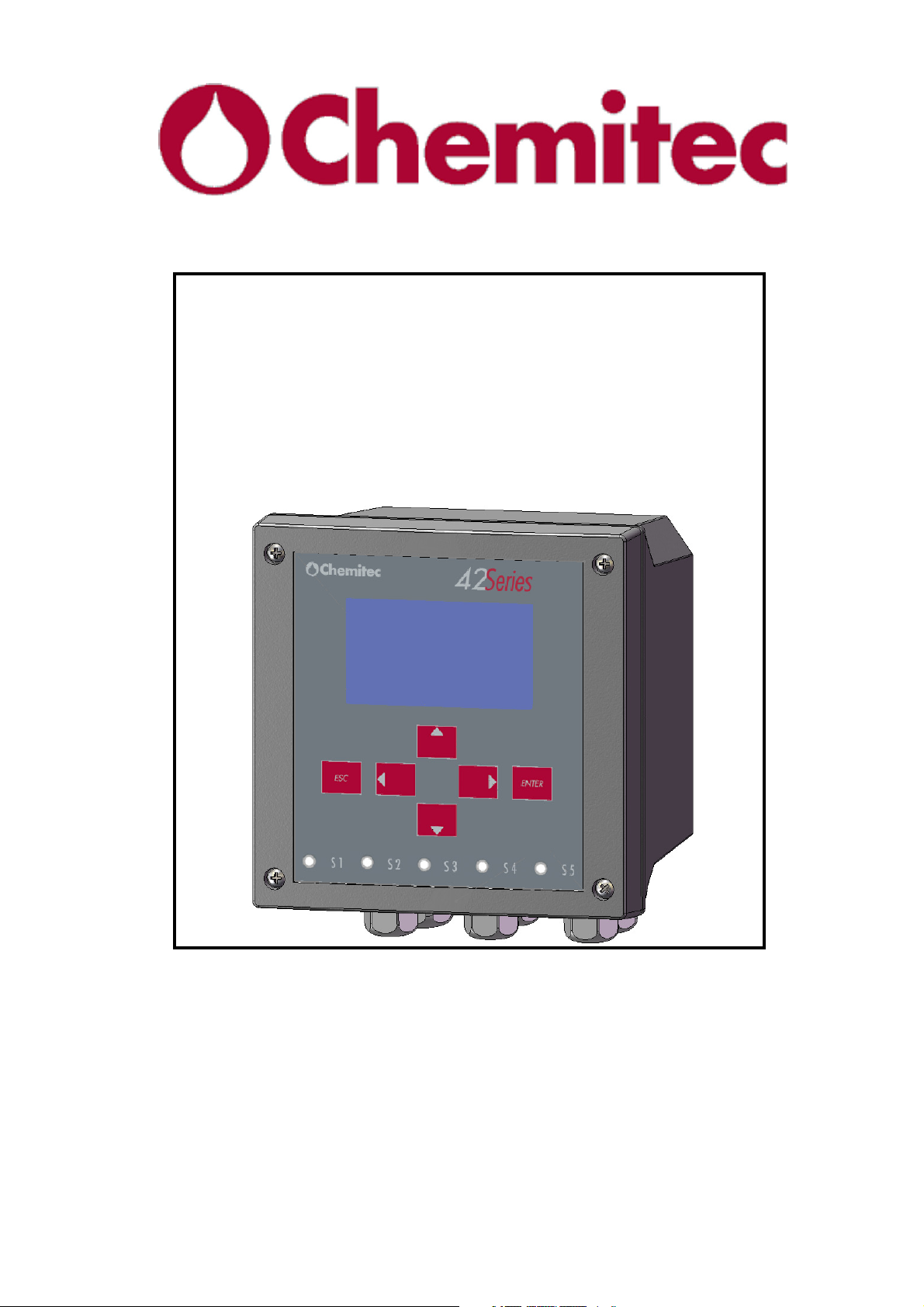
4204
FLOW METER
With ULTRASOUND
measurement sensor
TECHNICAL MANUAL
P/N:
………………….
Rev. 5 Ver. 3.4
RELEASE December 2016
Page 2

GENERAL CLAUSES
Although we have paid maximum attention and care in processing this document,
CHEMITEC s.r.l. cannot guarantee the exactness of all information herein contained
and thus cannot be held liable for errors that this may entail nor for the damages that
may result from the use or application thereof.
Material products, software and services shown in this document are subject to
evolution. In reference to characteristics of presentation and operation, CHEMITEC
s.r.l. shall reserve the right for any modifications without advance notice.
It is prohibited to reproduce or copy this manual, even partially, and through any
process.
COPYRIGHT
AUTHORISED SERVICE CENTRES
CHEMITEC s.r.l.
Via Isaac Newton, 28 – 50018 Scandicci – FLORENCE - ITALY
Page 3

4204
FLOW METER
TECHNICAL MANUAL P/N XXX-0000 Rev. 5 Ver. 3.4
TABLE OF CONTENTS
1 GENERAL ............................................................................................................................................................... 1
1.1 MANUAL INFORMATION ............................................................................................................................. 1
1.1.1 CONVENTIONS ........................................................................................................................................ 1
1.2 MANUFACTURER DECLARATION OF LIABILITY ................................................................................... 2
1.3 LIMITS OF USE AND SAFETY PRECAUTIONS .......................................................................................... 2
1.3.1 ELECTRIC SAFETY .................................................................................................................................. 2
1.3.2 SAFETY OF OPERATING ENVIRONMENT ............................................................................................ 3
1.4 GRAPHIC SIGNS ............................................................................................................................................. 4
1.4.1 DANGER SIGN .......................................................................................................................................... 4
1.5 PLATE DATA ................................................................................................................................................... 5
1.6 INFORMATION ON RECYCLING AND REUTILISATION OF MATERIALS............................................ 5
1.6.1 SPECIAL ATTENTION FOR CRITICAL COMPONENTS ....................................................................... 5
2 GENERAL DESCRIPTION ................................................................................................................................... 6
2.1 MAIN FEATURES ............................................................................................................................................ 6
2.2 UNIT HARDWARE MAIN FEATURES ......................................................................................................... 7
2.3 CONTROLS AND INDICATORS .................................................................................................................... 9
3 INSTALLATION ................................................................................................................................................... 10
3.1 COMPOSITION OF THE SUPPLY ................................................................................................................ 10
3.1.1 INSTALLATION OF WALL MOUNTED DEVICE .................................................................................. 10
3.1.2 INSTALLATION OF 144x144 ELECTRICAL PANEL DEVICE ............................................................. 11
3.1.3 TERMINAL BOARD CONNECTIONS .................................................................................................... 12
3.2 CONNECTING POWER SUPPLY LINE ....................................................................................................... 12
3.2.1 ELECTRICAL CONNECTIONS TO THE SYSTEMS .............................................................................. 13
3.2.2 INSTALLATION OF THE PROBE .......................................................................................................... 13
4 OPERATING MODE – GENERAL .................................................................................................................... 14
4.1 DISPLAYING SYSTEM ................................................................................................................................. 14
5 ENABLING THE SYSTEM ................................................................................................................................. 15
5.1 START ............................................................................................................................................................ 15
6 RUN MODE ........................................................................................................................................................... 16
7 PROGRAMMING MODE ................................................................................................................................... 19
7.1 ACTIVATION OF FUNCTIONS .................................................................................................................... 20
7.2 SETUP [1] ....................................................................................................................................................... 23
7.2.1 RELAYS [1.1] (Fig. 7-2) .......................................................................................................................... 24
7.2.1.1 Relays [1.1] .......................................................................................................................................... 24
7.2.1.1.1 K1÷KL5 [1.111÷1.115] ................................................................................................................ 24
7.2.1.1.1.1 Disable .................................................................................................................................... 24
7.2.1.1.1.2 PULSES [follows 1.111÷1.115] ............................................................................................. 24
7.2.1.1.1.3 Alarm [follows 1.111÷1.115] ................................................................................................. 24
7.2.1.2 Alarm [1.12] ........................................................................................................................................ 25
7.2.1.2.1 Loss of sensor connection ............................................................................................................. 25
7.2.1.2.2 Relay activation [follows 1.12] ..................................................................................................... 25
7.2.1.2.3 Eco loss [follows 1.12] .................................................................................................................. 25
7.2.2 SYSTEM SETUP[1.2] .............................................................................................................................. 26
7.2.2.1 Date/Time [1.21] ................................................................................................................................. 27
7.2.2.2 Communications [1.22] ....................................................................................................................... 27
7.2.2.2.1 Address [segue 1.22] ..................................................................................................................... 27
I
Page 4

4204
TECHNICAL MANUAL P/N XXX-0000 Rev. 5 Ver. 3.4
FLOW METER
7.2.2.2.2 Baud rate[1.22] .............................................................................................................................. 27
7.2.2.3 Language [1.23] ................................................................................................................................... 27
7.2.2.4 Password [1.24] ................................................................................................................................... 27
7.2.2.4.1 Status [1.241] ................................................................................................................................ 28
7.2.2.4.2 New [1.242] ................................................................................................................................... 28
7.2.2.5 Display [1.25] ...................................................................................................................................... 28
7.2.2.5.1 Contrast ......................................................................................................................................... 28
7.2.2.5.2 Back light ...................................................................................................................................... 28
7.2.3 LEVEL [1.3] ............................................................................................................................................ 29
7.2.3.1 Level Param[1.31] ............................................................................................................................... 29
7.2.3.2 Parameters [1.32] ................................................................................................................................. 29
7.2.3.2.1 h 0 Dist .......................................................................................................................................... 30
7.2.3.2.2 h max. ............................................................................................................................................ 30
7.2.4 FLOW [1.4] ............................................................................................................................................. 30
7.2.4.1 Generic Flow [1.41] ............................................................................................................................. 30
7.2.4.1.1 Units .............................................................................................................................................. 30
7.2.4.1.2 Decimal ......................................................................................................................................... 30
7.2.4.1.3 PMD .............................................................................................................................................. 30
7.2.4.1.4 Exponent ....................................................................................................................................... 31
7.2.4.2 Flow Param [1.42] ............................................................................................................................... 31
7.2.4.2.1 Q Max ............................................................................................................................................ 31
7.2.4.2.2 Cut off ........................................................................................................................................... 31
7.2.5 table [1.5] ................................................................................................................................................ 31
7.2.5.1 Set up for the “Bazin” type overflow .................................................................................................. 32
7.2.6 RESET SETUP [1.6] ............................................................................................................................... 33
7.3 MANUAL CONTROL [2.0] ........................................................................................................................... 34
7.3.1 TEST LEVEL [2.1] .................................................................................................................................. 34
7.3.2 RELAYS [2.2] ......................................................................................................................................... 34
7.3.3 ANALOG OUTS [2.3] ............................................................................................................................. 34
7.4
MA
ANALOGUE
OUTPUT
[3.0] ...................................................................................................................... 35
7.4.1 OUT 1 ...................................................................................................................................................... 35
7.4.2 OUT 2 ...................................................................................................................................................... 35
7.5 ARCHIVE [4.0] ............................................................................................................................................... 36
7.5.1 TOTALIZER ............................................................................................................................................. 37
7.5.1.1 Display Data [4.11] ............................................................................................................................. 37
7.5.1.2 Totalizer File [4.12] ............................................................................................................................. 37
7.5.2 FLOW [4. 2] ............................................................................................................................................ 37
7.5.2.1 Visualise Data [4.21] ........................................................................................................................... 37
7.5.2.2 Capacity Archive [4.22] ...................................................................................................................... 38
7.6 EXIT MENU [5.0] ........................................................................................................................................... 38
8 MAINTENANCE ................................................................................................................................................... 39
8.1 SPECIAL ATTENTION FOR CRITICAL COMPONENTS .......................................................................... 39
9 MODBUS PROTOCOL ........................................................................................................................................ 40
10 WARRANTY ......................................................................................................................................................... 44
11 REQUEST FOR SERVICE .................................................................................................................................. 45
11.1 PROCEDURE FOR SERVICE REQUEST ..................................................................................................... 45
11.2 MAIN CHEMITEC OFFICES ......................................................................................................................... 45
II
Page 5

1 GENERAL
1.1 MANUAL INFORMATION
This document contains copyrighted information. They may be subject to modifications and
updates without notice.
Printing sequence
First edition: µACP 4204 – Rev. 0 Ver 1.1
This manual is integral part of the instrument. At first installation of the instrument, the operator
must carry out an accurate verification of the content of the manual in order to verify its integrity
and completeness.
In case it shows to be damaged, incomplete or unsuitable, please contact CHEMITEC in order to
immediately integrate or replace the non-complying manual.
The official versions of the manual, for which CHEMITEC is directly responsible, are the Italian
and English versions. For Countries with languages different than those versions above mentioned,
the official manual in the one in Italian language. CHEMITEC shall not be held responsible for any
translations in different languages carried out by distributors or users.
Compliance with the operating procedures and warnings described in the present manual is an
essential requirement for the correct operation of the instrument and to guaranty safety for the
operator.
Before installing/operating the instrument, the manual must be read in its entirety while standing in
front of the same, in order to become very familiar with the operating procedures, controls,
connections to peripheral instruments and precautions for the safe and correct use of it.
The user manual must be saved, integral and legible in all of its parts in a safe place and, at the
same time, quickly accessible to the operator during installing operations, use and/or reviewing the
installation
4204
FLOW METER
TECHNICAL MANUAL P/N XXX-0000 Rev. 5 Ver. 3.4
1.1.1 CONVENTIONS
This manual utilises the following printing conventions:
The notes contain important information to be emphasised with respect to rest of the text.
They generally contain information useful for the operator in order to execute correctly and
optimise the operating procedures.
Warning messages appearing in the manual before procedures or operations which must be
respected in order to prevent possible loss of data or damages to the instrument.
Caution messages appear in the manual near descriptions of procedures or operations
which, if carried out incorrectly, may cause damages to operators or users.
NOTE
WARNING
CAUTION
1
Page 6

1.2 MANUFACTURER DECLARATION OF LIABILITY
CHEMITEC shall be liable for the safety, reliability and performance of the instrument only if
utilised in compliance with the following conditions:
• Calibrations, modifications and repairs must be performed by personnel expressly qualified and
authorised by CHEMITEC.
• Opening of the instrument and access to its internal parts must be performed solely by personnel
qualified for the maintenance and appropriately authorised by CHEMITEC.
• The facility which the instrument operates, must conform to the safety requirements.
• The facility electrical system must be installed according to regulations and be perfectly
efficient.
• The feasible replacement of parts of the instrument and accessories, must be done with others
of the same type and specifications.
• Use and maintenance of the instrument and relative accessories must be carried out in
compliance with instructions described in the present manual.
• The present manual must be kept integral and legible in all of its parts
4204
FLOW METER
TECHNICAL MANUAL P/N XXX-0000 Rev. 5 Ver. 3.4
1.3 LIMITS OF USE AND SAFETY PRECAUTIONS
In order to guaranty safety for the operator together with the correct operation of the instrument, it is
necessary to operate within the admitted limits and implement all the precautions listed further:
CAUTION
Before operating the instrument, verify that all the safety requirements have been met. The
instrument must not be powered–up or connected to other instruments until all safety
conditions are met.
1.3.1 ELECTRIC SAFETY
CAUTION
All connections present on the instrument are insulated from the ground environment
(ground not insulated).
DO NOT connect any of these connections to the ground.
In order to guaranty the maximum safety conditions for the operator, we recommend following
faithfully all instructions listed in this manual.
• Supply the instrument with line voltage according to the specification (85÷265V ac
50/60Hz).
• Replace immediately damaged parts. Cables, connectors, accessories or other parts of the
instrument found to be damaged or not operating correctly, must be immediately replaced. In
such case, contact the nearest authorised technical service centre.
• Utilise only accessories and peripherals specified by CHEMITEC. To guaranty the meeting
of all safety requirements, is necessary to utilise exclusively accessories specified in this
manual, which have been tested together with the instrument. Use of other manufacturers’
accessories and consumable materials or not specifically indicated by CHEMITEC, does not
guaranty safety and correct operation of the instrument. Utilise exclusively peripherals that
comply with the regulations of the category to which they belong.
2
Page 7

1.3.2 SAFETY OF OPERATING ENVIRONMENT
• The 4204 unit is watertight against any infiltration of liquids. Avoid subjecting the
equipment to risks of seepage, sprays or anything else and do not use in areas in which such
risks are possible. Any power units in which liquids may have accidentally fallen should be
immediately turned off, cleaned and checked by authorised and qualified personnel.
• Once programming has been completed, close the transparent panel.
• Protection.
4204 Wall mounting
− IP66 EN60529
− EMI /RFI CEI EN55011 - 05/99
4204 144x144 Panel mounting
− IP10 EN60529
− EMI /RFI CEI EN55011 - 05/99
• Utilise the instrument within the specified environmental limits of temperatures and
humidity. The instrument is constructed to withstand operation in the following environmental
conditions:
− environmental operating temperature 0°C ÷ +50°C
− storage and transporting temperature -25°C ÷ +65°C
− relative humidity 10% ÷ 95%RH - non-condensing
The plant, in which the instrument is introduced, must be constructed according the
operating requirements provided by the current legislation.
CAUTION
4204
FLOW METER
TECHNICAL MANUAL P/N XXX-0000 Rev. 5 Ver. 3.4
The instrument must be perfectly introduced in the plant.
The plant must be operated in full compliance with the provided safety regulations.
Any signals of faults to the power unit should be placed in an area constantly controlled by
operative personnel or plant assistants.
Failure to comply with one of these conditions may cause the unit “logic” to operate in a
potentially dangerous mode for the users of the service.
Therefore, we recommend to the servicing and/or maintenance personnel to operate with
the utmost thoroughness, promptly signalling any variations of the safety parameters, in
order to prevent the development of dangerous conditions or potentially dangerous
conditions.
Because the above explained considerations do not fall under the possibilities of control by
the instrument in the subject, the manufacturer shall not in any way or fashion be held
responsible for any damages that such malfunctions may cause to persons or things.
3
Page 8
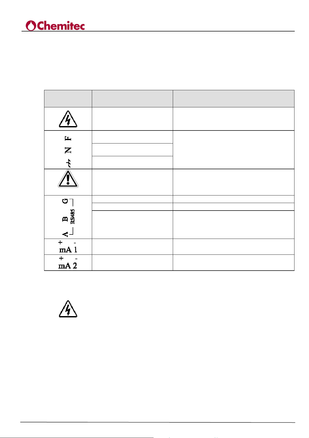
1.4 GRAPHIC SIGNS
The following Table 1-1 indicates the drawings, relative descriptions and position of all the graphic
signs placed on the instrument panel and on any other external instruments or devices to which it
can be connected.
Table 1-1 Graphic signs
SIGN DESIGNATION POSITION
4204
FLOW METER
TECHNICAL MANUAL P/N XXX-0000 Rev. 5 Ver. 3.4
Danger sign
Sign placed near the terminals for the connection
to line voltage (See Paragraph 1.4.1)
Phase
Neutral
Grounding protection
Caution! Consult the attached
documentation
Signs placed near the connections of the
instrument to the power supply line (See Paragraph
3.1.1)
Symbol positioned in correspondence with the
points in the manual that require special attention
Positive
Negative
Terminal
Analogue output no. 1
Analogue output no. 2
Positive pole of the connector RS485
Negative pole of the connector RS485
Sign placed near the cable shielding for RS485
0/4 ÷20mA galvanic separation
0/4 ÷20mA galvanic separation
1.4.1 DANGER SIGN
The sign indicates DANGER for the operator. It is placed inside the instrument near the
points where the voltages present may be dangerous.
We recommend paying maximum attention.
Especially when the sign, placed near the cable connections to peripherals, refers to the attentive
reading of the user manual for a correct and safe connection.
4
Page 9
4204
TECHNICAL MANUAL P/N XXX-0000 Rev. 5 Ver. 3.4
FLOW METER
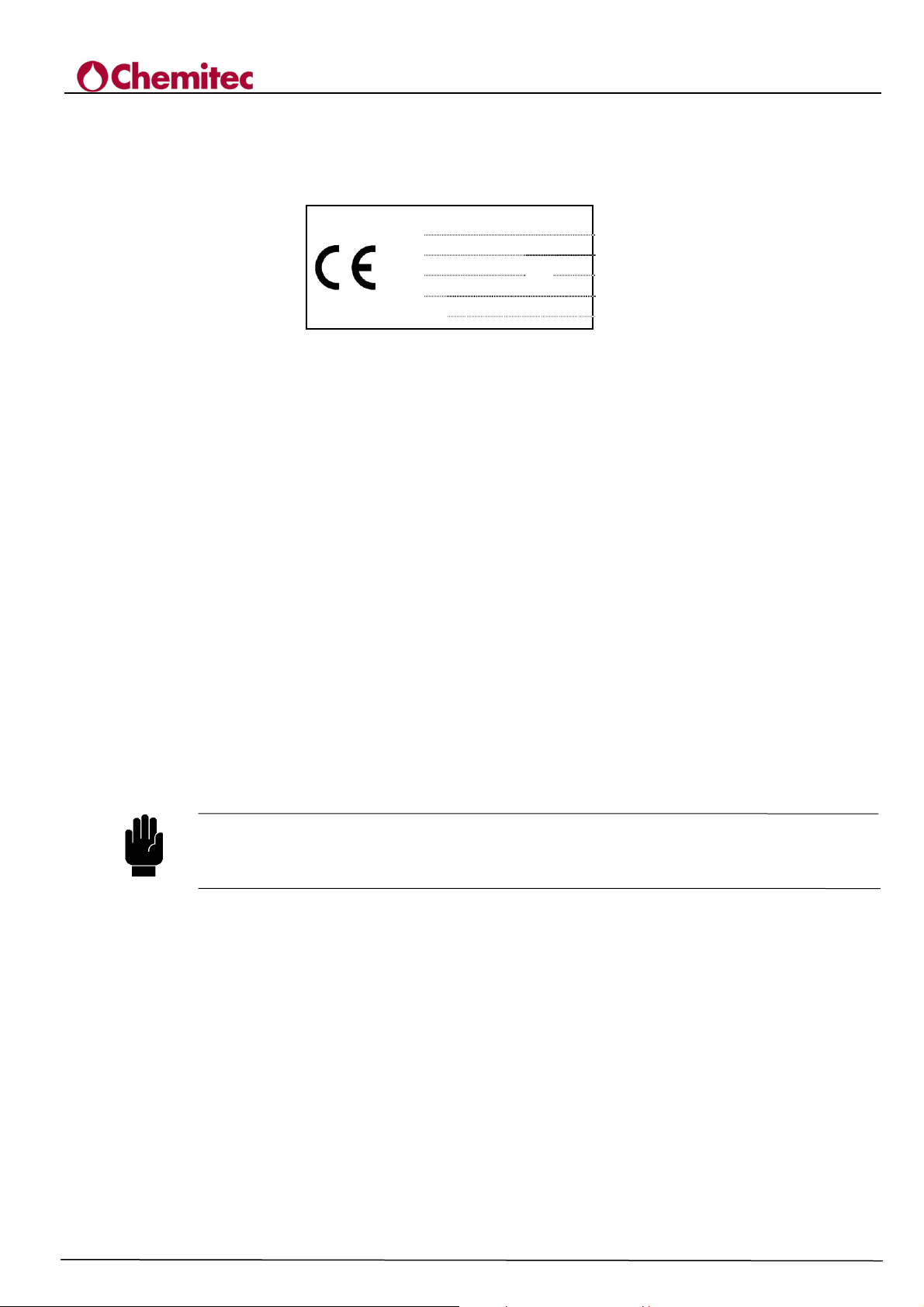
1.5 PLATE DATA
The plate must be similar to the one reproduced in Figure 1-1.
Figure 1-1 Configuration of the Unit Number Plate
Mod.
SN.
Volt
Fuse
SW Ver.
4204
XXXXXXX
100-240 Vac/dc
3.15
X.X
Hz
50/60
1.6 INFORMATION ON RECYCLING AND REUTILISATION OF MATERIALS
CHEMITEC objectives, in compliance with the specific European directives, including the directive
2002/95/CE, traditionally identified by RoHS, aims at continuously improving planning and
manufacturing of its own instruments, in order to reduce to the minimum the negative impact on
environment about handling the component parts, consumable materials, packing and instrument
itself, at the end of its useful life.
Packing are conceived and produced in order to allow their reutilisation or recuperation, including
recycling of most of the materials and to reduce to the minimum the amount of wastes and residuals
to dispose of. To guaranty a correct environmental impact, the instrument has been planned with
the utmost circuitry miniaturisation possible and with the least differentiation possible of materials
and components, through selection of substances that guarantee maximum recyclability and the
maximum reutilisation of the parts and a disposal of them devoid of ecological risks.
The instrument has been manufactured in a way to facilitate separation and disassembling of
materials containing polluting substances with respect to the others, especially during maintenance
and parts replacement operations, in accordance with the requirements of the Directive 2002/96/CE,
traditionally identified by RAEE.
WARNING
Disposal/recycling of packing, consumable materials or instrument itself at the end of its
useful life, must be carried out according to the provisions imposed by regulations and
directives currently in force in the country in which the instrument is utilised.
1.6.1 SPECIAL ATTENTION FOR CRITICAL COMPONENTS
The instrument is fitted with an LCD, liquid crystal display, which contains small quantities of toxic
materials.
5
Page 10
2 GENERAL DESCRIPTION
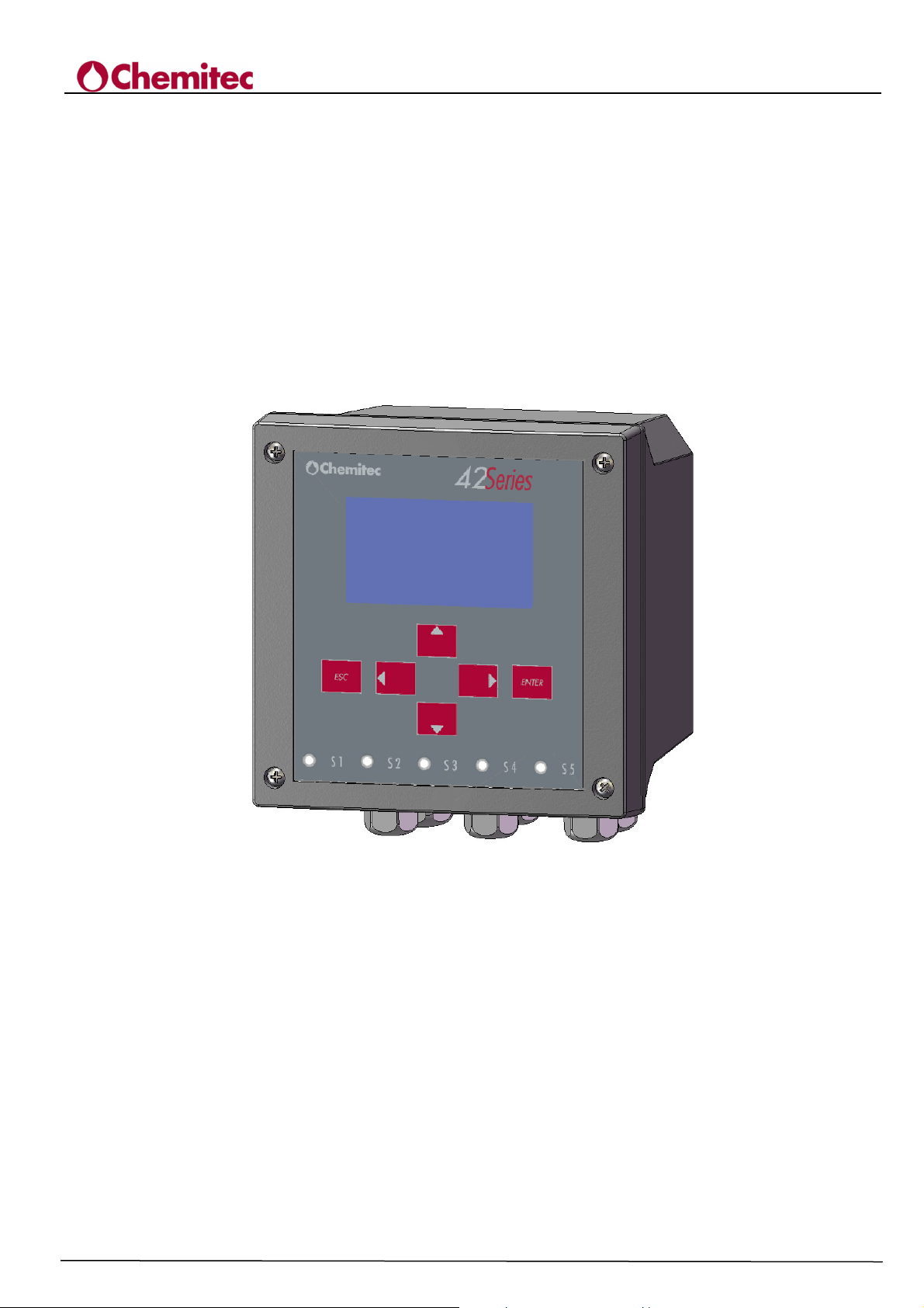
The unit shown in Figure 2-1 is provided for wall installation.
It is supplied by the line (85÷265Vac-50/60Hz) through power supplier Switching.
This instrument has been conceived as flow metre through an ultrasound probe with automatic
temperature compensation with display of the following at the same time:
• immediate flow (with a Bargraph percentage scale);
• total volume
• temperature
• status of the analogical outputs
• counters
4204
FLOW METER
TECHNICAL MANUAL P/N XXX-0000 Rev. 5 Ver. 3.4
Figure 2-1 – Ultrasounds level meter and regulator (4204)
2.1 MAIN FEATURES
• Ultrasound flow measurement
• Automatic temperature compensation
• Bubble 6 keys programming keyboard
• Graphic Display
• Serial Output RS485 MOD BUS RTU
• 2 Programmable Analogue Outputs
• 5 Relay output
• 1 Relay output for Eco loss alarm
• Total counter that cannot be reset
• Partial counter accessible operatively
6
Page 11

2.2 UNIT HARDWARE MAIN FEATURES
• Internal Data logger (flash 4 Mbit) with possibility of graphic and table display of
measurements trends.
• Five independent set points for threshold control, with programming of the work field
(hysteresis).
• Digital alarm output for eco loss.
• Primary output 0/4¸20mA with programmable limits for Flow/Temperature.
• Secondary output 0/4¸20mA with programmable limits for temperature/flow/level.
The technical specifications of the instrument are listed in Table 2-1, while the operating
specifications are listed in Table 2-2.
Table 2-1 Technical Specifications
4204
FLOW METER
TECHNICAL MANUAL P/N XXX-0000 Rev. 5 Ver. 3.4
Characteristics of dimensions
Measurement field
Precision
Unit of measurement Flow: mc/h, lt/sec – Level: m, cm, mm – Temperature: °C
Decimals Flow: 3 – Level: 3
RETTANG (rectangular spout) / TRAPEZ (Cipolletti spout) / VENTURI (Venturi
Types of devices/exponents for each PMD
calculation (primary measuring device)
2 counters
PARSHALL (Parshall channel) / LEOPOLD (Leopold Lagco channel) / STRAM. V (V
Absolute at 9 figures - saved on Flash PROM not re-settable – Partial at 9 figures re-
Level 0.30 ÷ 5.00 mt. - TemperaturE: 0 ÷ 100 °C
OTHER (freely programmable exponent)
Flow 0 ÷ 9999 mc/h
Characteristics of the
Hardware
LCD STN Graphic 128x64 Backlit
DISPLAY screen
Controls 6 Bubble Keys
DATA LOGGER Internal with Flash 4 Mbit
Serial output n.1 RS485 Galvanic separated MODBUS RTU
Analogue outputs
Relay Outputs
Digital Input n.5 Programmable
Power Supply 100÷240Vac/dc 50-60Hz – (Optional 24Vac/dc) – Transformer Insulation 4KV
Average power draw < 12W
Contemporary display of: Instant flow (absolute + bargraph for percentage of the
scale), Volume counted, Temperature, Status of the digital outputs, alarm events.
In scrolling: Level, Status of the analogical outputs, Re-settable counter
n.2 Programmable Galvanic Separated
1st Output: Flow / Temperature - 2nd output: Flow / Temperature / Level
n.5 in Exchange for Thresholds - n.1 in Exchange for Alarm– (max load 1A ar 230V
± 0.2% F.S.
channel) /
spout) /
settable
ac resistive)
7
Page 12

Table 2-2 Operating Specifications
4204
FLOW METER
TECHNICAL MANUAL P/N XXX-0000 Rev. 5 Ver. 3.4
Measurement Recording
Recordings Intervals 1/275/10/15/20/30/60 min 5/10/30 min. 1/2/6/12/24 h.
Type Circular /Filling Circular / Filling
Graphic display of the minimum, maximum
Display
and average values of the period and of
Analogue Outputs
Quantity/Size Flow / Temperature Flow / Level / Temperature
Type 0.00 ÷ 20.00 mA / 4.00 ÷ 20.00 mA 0.00 ÷ 20.00 mA / 4.00 ÷ 20.00 mA
Range Limit Programming: Lower / Upper Limit Programming: Lower /Upper
Maximum Load 500 Ohm 500 Ohm
Alarm Output according to NAMUR 2.4 mA (with Range 4/20mA) 2.4 mA (with Range 4/20mA)
5 relay outputs
Function– selectable Threshold Pulses
Programming ON-OFF with hysteresis
Alarm
Function Eco loss alarm
Programming
Relay operation Closed/Open
Operating Conditions
Operating Temperature 0÷50°C
Transport and Storage -25÷65°C
Humidity 10-95% non condensed
Protection Closed IP66 EN60529
EMI / RFI CEI-EN55011 – 05/99
Instant flow Volume counted
Table
the Zoom function
Primary Secondary
De-multiplier: 1,10,100mc/h
Duration: 250,500,1000,2000 msec
Time Out ( eco loss time):
00:00 ÷ 24:00 h
8
Page 13
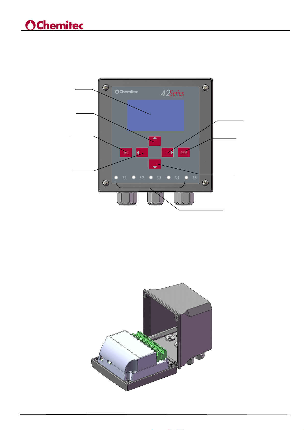
2.3 CONTROLS AND INDICATORS
Controls and indicators are grouped on the front of the Unit so that they can be easily available for
the operator.
Figure 2-2 identifies all the Unit controls and connecting devices.
1
3
4204
TECHNICAL MANUAL P/N XXX-0000 Rev. 5 Ver. 3.4
FLOW METER
4
5
7
6
8
2
1. LCD Display
2. S1÷S5
3. UP Key
4. RIGHT Key
5. ESC Key
6. ENTER Key
7. LEFT Key
8. DOWN Key
Figure 2-2 – Frontal Panel, Unit Wall model
Figure 2-3 – Access to the terminal box
9
Page 14

3 INSTALLATION
Although the unit is suitable for installation in outdoor environments, it is recommended to avoid
direct exposure to sun and weather. Before installing the 4204 carefully read the instructions
provided below.
3.1 COMPOSITION OF THE SUPPLY
The supply consists of just one package which contains the following parts:
• 1 electrical control and command panel PN ............?????
• 1 Technical Manual PN ............?????
3.1.1 INSTALLATION OF WALL MOUNTED DEVICE
The wall must be completely smooth in order to allow for perfect adhesion of the device.
4204
FLOW METER
TECHNICAL MANUAL P/N XXX-0000 Rev. 5 Ver. 3.4
Figure 3-1 – Dimensions and encumbrance of the wall mounted device
Mechanical Dimensions
Dimensions (L x H x P)
Fixing depth
Material
Mounting
Weigth
Frontal Panel
ABS Grey RAL 7045
Policarbonate UV Resistant
4204
144x144x122,5mm
122,5mm
Wall
1 Kg
Open the instrument, open the pre-shaped holes and fix the instrument itself to the wall. Use the
provided plastic caps to close the holes.
The terminal box for connections is located on the bottom of the gear case and it is necessary to
keep it separated from other equipment by at least 15 cm. in order to make it easier to use. Keep
away from water drips and/or sprays of water from adjacent areas in order to safeguard the
instrument during programming or calibration stages.
10
Page 15
TECHNICAL MANUAL P/N XXX-0000 Rev. 5 Ver. 3.4
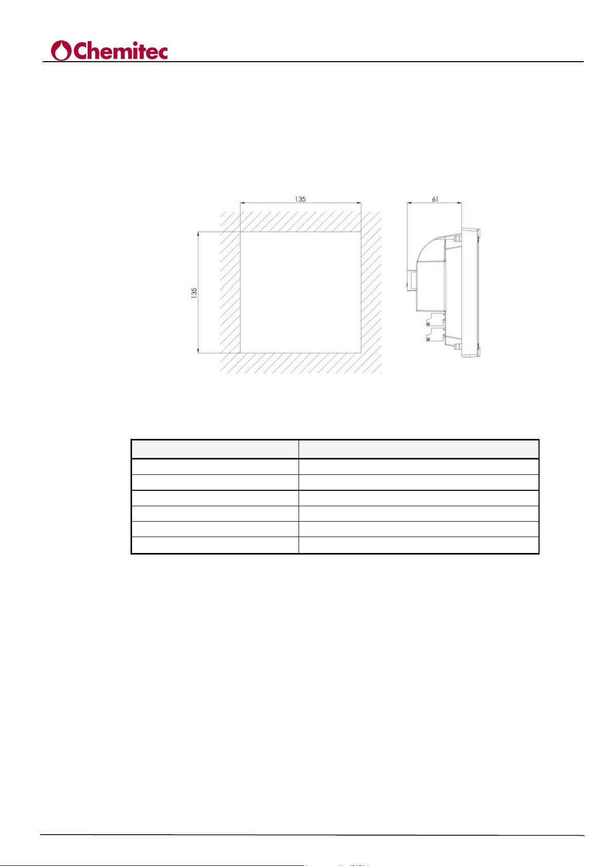
3.1.2 INSTALLATION OF 144X144 ELECTRICAL PANEL DEVICE
The wall must be perfectly smooth in order to allow for perfect adhesion of the electrical panel close
to the device.
The net depth of the panel must be at least 130 mm.
The thickness of the panel must not exceed 5 mm.
The perforation DIMA must comply with the following layout:
4204
FLOW METER
Figure 3 – Encumbrance and Dima for perforation of the panel
Mechanical Dimensions
Dimensions (L x H x P)
Fixing depth
Material
Mounting
Weight
Frontal Panel
4204 144x144 Panel Mounted
144x144x86,5mm
70mm
ABS Grey RAL 7045
Panel
0.7 Kg
Policarbonate UV Resistant
The locking of the control unit to the panel is made through the mounting backplate, which is fixed
to the panel on the inner side, using the apposite screws.
11
Page 16
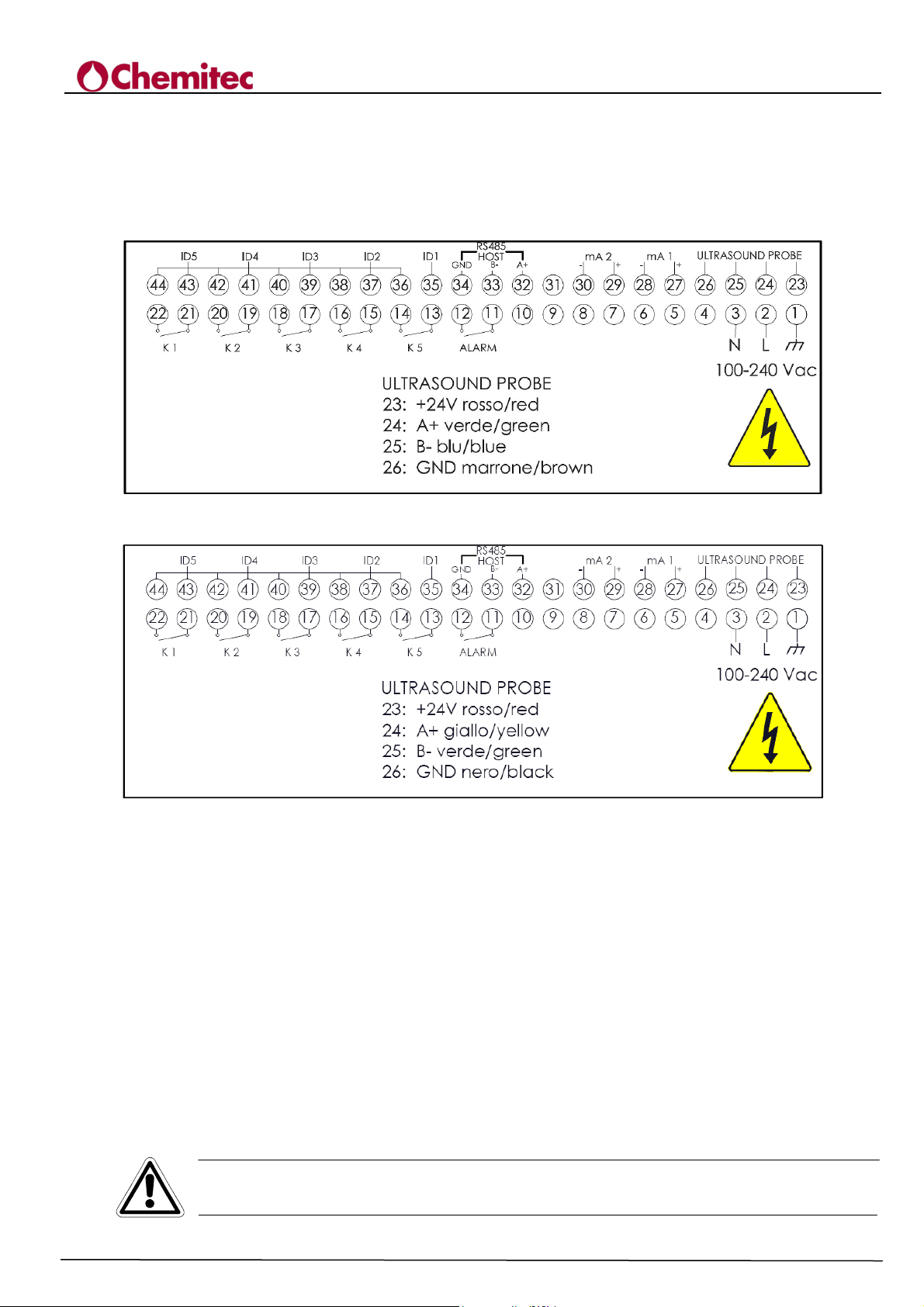
3.1.3 TERMINAL BOARD CONNECTIONS
The terminal board connections and the definitions of the Unit connections to the plant to be placed
under control are shown in Figure 3-2 and 3-3 (depending by the connected probe).
It shows the connections diagram viewable on the cover of the connections housing.
Figure 3-2 Electric connections for S425
4204
FLOW METER
TECHNICAL MANUAL P/N XXX-0000 Rev. 5 Ver. 3.4
Figure 3-3 Electric connections for S425/C
3.2 CONNECTING POWER SUPPLY LINE
If all possible make sure that there aren’t any cables assigned to the controls of other power drawing
equipments near the unit or on the same path of the connecting cable, which could create inductive
interferences for the instrument.
As much as possible, apply to the instrument stabilised power voltage according to the information
on the plate.
Absolutely avoid connecting the instrument to indirect/ reconstructed power supplies, for example,
through the use of transformers, where this reconstructed power goes to supply other systems
besides the unit (i.e.: inductive type), because this procedures generate high voltage spikes which
once they are radiated it’s difficult to block and/or eliminate them.
CAUTION
The electric line must be fitted with an appropriate circuit breaker and magnetothermic
switch, in compliance with good rules of installation
12
Page 17

In any case, it is always advisable to verify the quality of Grounding. Often Ground connections,
found mostly within industrial environments, are themselves generators of interferences; where in
doubt about the quality, it is preferable to connect it to a pole dedicated only to the unit plant.
3.2.1 ELECTRICAL CONNECTIONS TO THE SYSTEMS
CAUTION
At the time pf starting the connections between the Unit and External Utilities, make sure
that electric board is turned-off and the cables coming from the Utility are not live.
• The Unit connections to the System must be carried out according the electric diagram of the
terminal board shown in Paragraph 3.1.1. The Unit is electronically protected, therefore, besides
the precautions on the power supply; it does not require special attentions.
• In reference to the sensor, it can be installed up to a distance of ~ 1000m from the Unit, without
causing any appreciable loss of signal.
• The position of the sensor should be between the limits the defined in the Chapter "Installation".
4204
FLOW METER
TECHNICAL MANUAL P/N XXX-0000 Rev. 5 Ver. 3.4
3.2.2 INSTALLATION OF THE PROBE
• Protect the probe from direct sunlight and reverb
• Wait at least 30 minutes after the first power on before calibrating the distance
• Keep the probe closer to the maximum water swing + 30 cm to prevent the air between the
projection and the water from assuming values that are too different from the probe
13
Page 18

4 OPERATING MODE – GENERAL
This chapter describes the procedures that must be followed to enable all the functions of the
programme. The description is distributed between text and Figures:
• The Figures show all the menus and submenus as they appear on the display when enabled.
• The text analyses all items of the various menus and showing, for each of them, the enabling
procedures, functions they perform and range of values that can be set, whenever requested to
enter numeric values.
• All settings under the control of the Programme are described in a specific paragraph listed in
the index.
This editorial technique, even though makes numbering paragraphs complex, it offers a
noticeable advantage of transforming the index in a simple and powerful tool for the search
because it lists all the subjects and it indicates where they are discussed.
4.1 DISPLAYING SYSTEM
The displaying of the system is done through graphic displays, which allows viewing all the various
programming menus and, in operating mode, (“RUN”), the display of operating settings inputted
and their operating status.
• The operative methods related to activation of the System are described in Chapter 5.
• The operative methods related to the "RUN” menu are described in Chapter 6.
• The operative methods related to the “SETUP” menu are described in Chapter 7.
4204
FLOW METER
TECHNICAL MANUAL P/N XXX-0000 Rev. 5 Ver. 3.4
14
Page 19

/s
19
5 ENABLING THE SYSTEM
After installing the electronic central control unit, it is necessary to go on programming the
software, which will allows for “personalising” the settings for a correct use of the instrument.
TURN-ON the instrument by supplying power to it. The unit is not equipped with a switch for
power supply; it is activated automatically with connection to the network.
5.1 START
At the first System Start-up the system initialisations are carried out, which should occur during
installation or in case of power interruption which, if not modified, will depend from the settings
present on the flash disk.
During this phase a check of the flash disk is performed and, if errors are detected, the instrument is
blocked and the following message is displayed:
“FLASH DISK ERROR”
In the presence of this kind of error, request intervention from technical assistants. If, on the
contrary, everything runs smoothly, the programme will load the operative set-up parameters and
will start to operate with them as a base.
During a parameter recall operation, memorisation errors may occur. If this is the case, the
programme will cancel loading of these parameters and the intervention of technical assistants. If
everything runs smoothly, the set-up parameters set by the operator will be loaded; if errors are
encountered the following message will appear:
4204
FLOW METER
TECHNICAL MANUAL P/N XXX-0000 Rev. 5 Ver. 3.4
“DEFAULT SETUP LOADED”
indicating that the default parameters will be loaded (and used); to continue press the "ENTER" key.
This message will also appear if programming has never been carried out before (therefore the setup parameters in the flash disk have never been registered).
A bad quality of display may depend from an incorrect adjustment of the display contrast.
Contrast regulation may be set when the device is turned on by working with the "UP" or "DOWN"
key at the same time as feeding of the power unit (Fig. 5-1).
The contrast reader will appear indicating the percentage value which, in standard conditions,
should be between 65%÷70%. Once the best level of contrast has been achieved, press “ENTER”.
The programme will enter a "RUN" mode.
Contrast may be regulated operatively using the "CONTRAST" function as described in paragraph.
7.2.2.5.1.
12/09/05 16:41
0003496.54m3
Figure 5-1 – Contrast Mode Flow-Chart
DOWN 220V
0 l
69%
ENTER
15
Page 20
6 RUN MODE
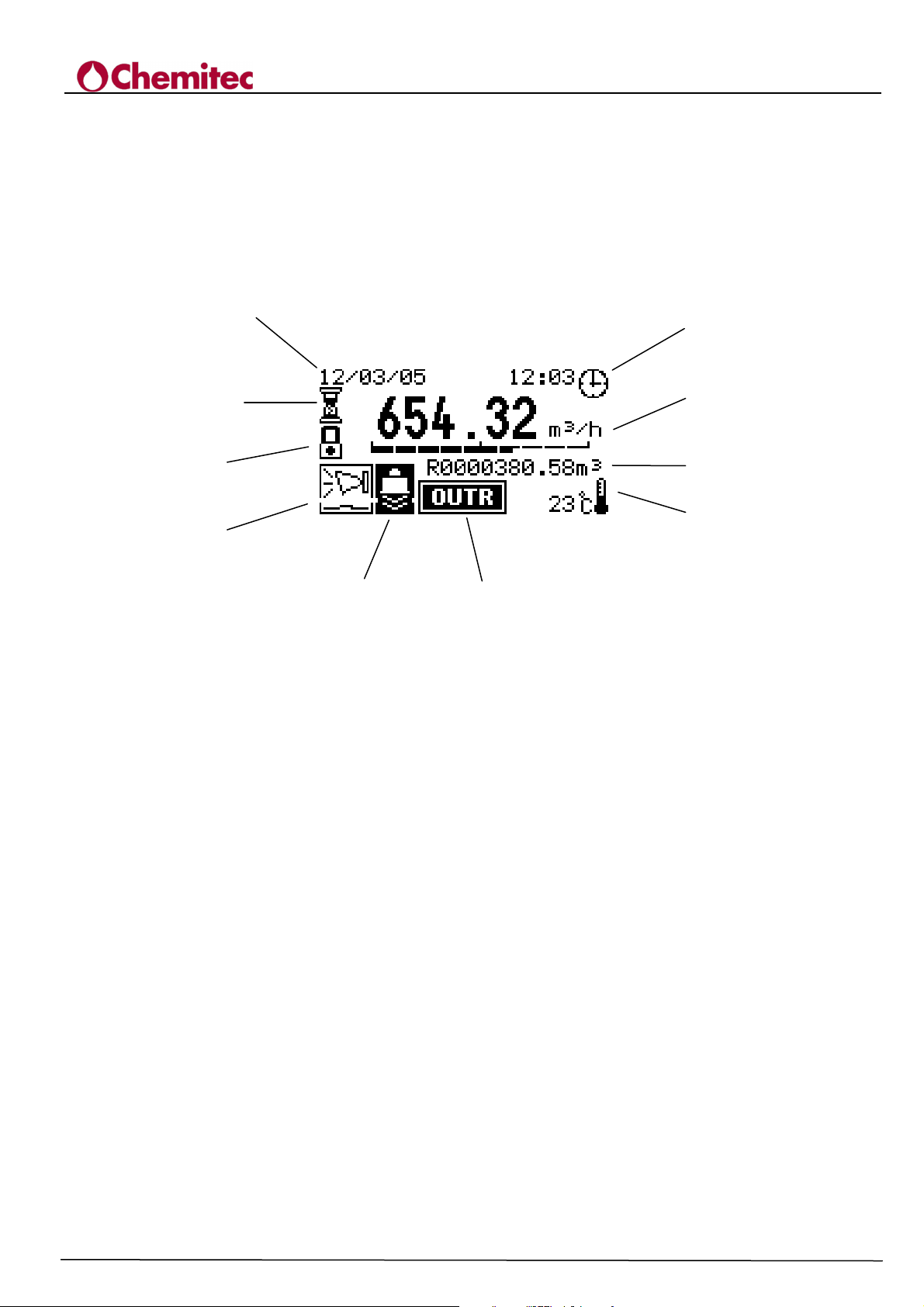
This mode keeps operation of the plant under control in real time.
The operative parameters are represented on the screen by the power unit, according to the symbols
shown in Figure 6-1 and in Table 6-1.
Table 6-1 illustrates the operative symbols of the "RUN" mode, the meaning of which is as follows:
1
2
3
4
4204
TECHNICAL MANUAL P/N XXX-0000 Rev. 5 Ver. 3.4
12
11
9
7
FLOW METER
5
Figure 6-1 Typical Run Mode Displayed
6
16
Page 21
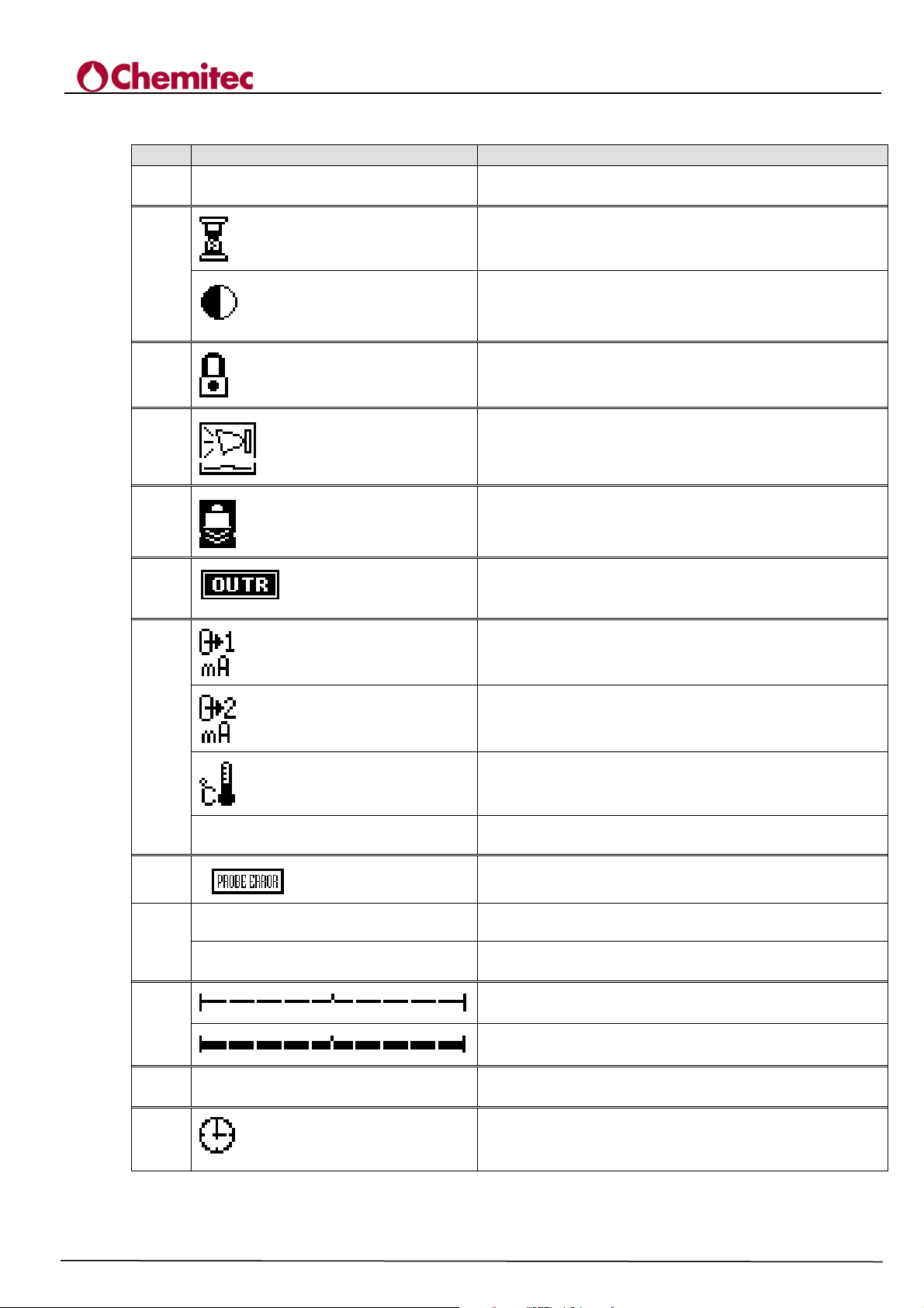
Table 6-1 Operating symbols
DISPLAY DESCRIPTION
1 12-04-05 Syatem Date
4204
FLOW METER
TECHNICAL MANUAL P/N XXX-0000 Rev. 5 Ver. 3.4
2
3
4
5
6
7
Wait- Freeze measurements and outputs phase
Contrast
Password Enabled
If communication is lost, "PROBE ERROR" will
appear in the middle of the screen
If the eco is lost for a period exceeding the period
indicated, icon 4 will be activated.
Flashing icon - Maximum flow exceeding the
maximum flow set
Output Value n.1 (in mA)
Output Value n.2 (in mA)
Actual Temperature Value (in Centigrade)
0 cm Value of the level of the recess
8
9
10
0000000.00 m3
R
0000000.00 m3
Alarm indicating loss in connections with the probe
primary counter
re-settable counter
0% of the scale
100% of the scale
11
12
0.00 m3/h - 1/sec.
Hourly flow in the unit of measurement selected
Solar time
17
Page 22
4204
Are you sure ?
/s
19
/s
19
/s
0.0cm
/s
0.0
TECHNICAL MANUAL P/N XXX-0000 Rev. 5 Ver. 3.4
FLOW METER
Programming Mode
220V
ENTER
12/09/05 16:41
0 l
0003496.54m3
ESC
ESC
ESC
12/09/05 16:41
ENTER
UP
DOWN
12/09/05 16:41
0 l
0003496.54m3
UP
DOWN
12/09/05 16:41
0 l
0003496.54m3
0 l
R0000106.59m3
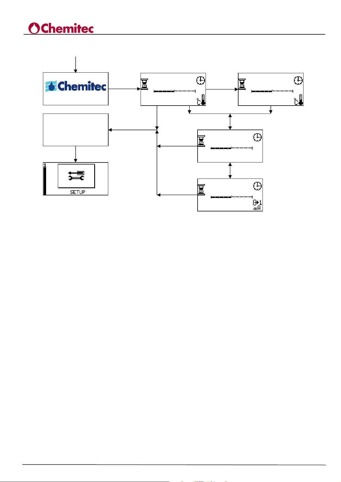
Figure 6-2 “RUN” Mode
18
Page 23

7 PROGRAMMING MODE
Apart from the "RUN" status, within which the System is fully operative, the programme of the
power unit includes a second status identified in the "PROGRAMMING" mode, allowing for all of
the parameters that specify the functionalities of the plant to be set.
If setting of the parameters clashes with the logic of the System, the programme will release
an "alarm" signal.
The meaning of the alarm is defined in paragraph 8.4.
Activation of the "PROGRAMMING" mode excludes the "RUN" mode and blocks activation
of the plant.
In order to enter the programming mode press “ESC”; a message will appear requesting further
confirmation: if "ESC" is pressed again, it will return to the "RUN" mode; if "ENTER" is pressed
all of the 4204 functions will be immediately disabled and it will move onto the
"PROGRAMMING" mode.
If the programme includes use of a "PASSWORD" (paragraph 7.2.2), it will be requested and it
should be inserted correctly otherwise the programme will not proceed.
If the “PASSWORD” is disabled or inserted correctly, the programme will enable the programming
menus.
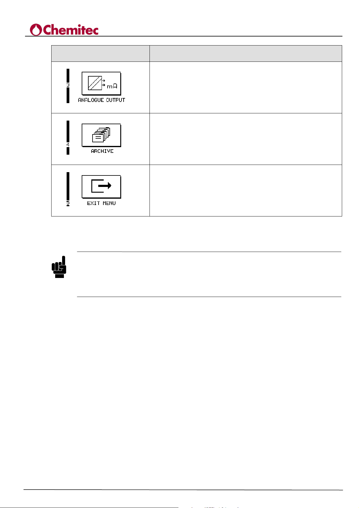
From this position by pressing “UP/DOWN” you can scroll all five menus available of the function
"PROGRAMMING", as shown in figure 7-1.
The menus are identified by a numerical code: it is indicated in the title of the corresponding text
and also in the Figures.
By entering the "PROGRAMMING" mode, the System will automatically move to position [1],
corresponding to:
CAUTION
CAUTION
4204
FLOW METER
TECHNICAL MANUAL P/N XXX-0000 Rev. 5 Ver. 3.4
“SETUP”
VIEW ON THE GRAPHIC
DISPLAY
DESCRIPTION
“SETUP”
Here are set all the basic settings for the operating logic
“MANUAL CONTROL”
Manual control and enabling of outputs and inputs
19
Page 24
4204
TECHNICAL MANUAL P/N XXX-0000 Rev. 5 Ver. 3.4
FLOW METER
VIEW ON THE GRAPHIC
DISPLAY
DESCRIPTION
“ANALOGUE OUTPUT mA”
Analogue outputs settings in current
“ARCHIVE”
Setting mode for filing and displaying data
“EXIT MENU”
Return to the measuring operating mode
Figure 7-1 Programming Menu
(“RUN”)
We strongly recommend that a test is carried out to set all of the parameters at least once
according to a sequence of presentation in order to become familiar with the procedures. It
is also important to remember that the operative methods are described only for paragraph
7.1; from paragraph 7.2 onwards they are proposed in a synthetic form, highlighting the
specific aspects that characterise them from standard ones.
7.1 ACTIVATION OF FUNCTIONS
This paragraph defines the operations that should be carried out to select the functions available and
to insert the parametric values necessary, in order to allow the power unit to operate in accordance
with user demands.
The method of selection of the menus is equivalent for all of the programme: therefore it is
sufficient to describe in detail, and only once, the procedure and refer to it systematically.
The objective of this paragraph is therefore to describe this procedure in a complete way by using
part of the first "SETUP" programming menu purely as an example.
The initial situation of this example is therefore of an operator who follows the instructions
indicated in Chapter 7 and has activated the "PROGRAMMING" method and therefore finds the
"SETUP" icon (1) on the screen, being the one that the programme automatically proposes when it
enters this phase.
a) In order to select the programming menu, press the "UP" or "DOWN" keys. The icons shown
in Figure 7-1 will appear. They are not only characterised by a different figure but also be a
progressive number that forms the initial part of a position code which visualises the position
reached within the structure in a very simple way.
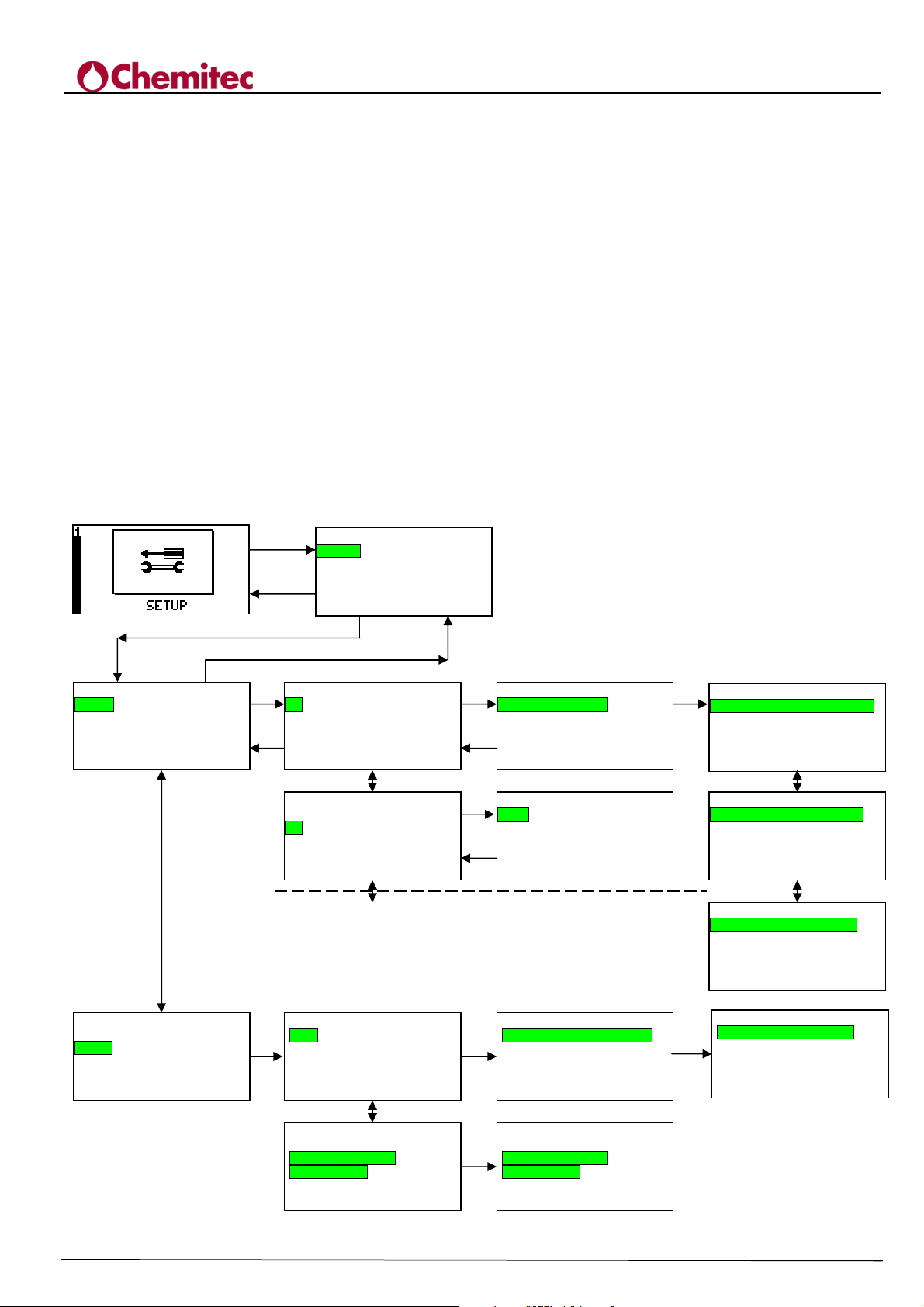
Figure 7-2 shows the structures of all of the programming menus complete with the position
codes. These codes are indicated (on the various screens and also in this manual) between
NOTE
20
Page 25

4204
TECHNICAL MANUAL P/N XXX-0000 Rev. 5 Ver. 3.4
FLOW METER
square brackets. In the case of this example, the menu corresponding to the following icon has
been selected
“SETUP” [1]
b) Press “ENTER” to activate the menu. The programme proposes the first of the operative
programmes on the screen. The presentation consists of:
− the position code
− the title
− the roll-down menu presenting the possible alternatives at that level
In the following example, representation is the following:
CODE: [1.0]
TITLE: “SETUP”
SUBMENU: “RELAYS”
“SISTEM SETUP”
“LEVEL”
“FLOW”
“RESET SETUP”
One of these instruments is always described as negative within a black string: this string
identifies the item that can be activated.
c) Press “UP” or “DOWN” to position the black string in the item of interest.
In the example, the black string is position on the 1st item, therefore on:
“RELAY OUTPUT”
d) Press “ENTER” to activate the item selected. The programme will illustrate the relative
screen, made up as follows:
CODE: [1.1]
TITLE: “RELAYS”
SUBMENU: “RELAYS”
“ALARM”
e) With a similar procedure to the one described in c); d); select and activate, press “ENTER”,
the first submenu:
“RELAY”
f) The programme will show the following screen:
CODE: [1.11]
TITLE: “RELAYS”
SUBMENU: “K1÷K5”
Press “UP” or “DOWN until reaching the black string on the relay chosen.
In the case in question, the relay chosen is K1. Press “ENTER” to activate it.
g) The course of the alternatives, in this branch of the programme, is completed and we then
move onto the parametric part, the part in which the System control data is intertwined.
Following these new requirements the screen is modified: apart from the usual elements such
as title and code, it lists the parameters connected to this field of the programme with the
relative parametric values currently set in the System. The titles and the codes are:
CODE: [1.111]
TITLE: “K1”
h) Apart from the title and the code (see g), the presence of a black string will be shown above
the wording:
21
Page 26

4204
TECHNICAL MANUAL P/N XXX-0000 Rev. 5 Ver. 3.4
FLOW METER
“FUNC”
This representation mode indicates other screens apart from the one represented, that contain
further parameters.
In order to visualise the alternatives available, proceed as follows:
− Position the black string on the item "FUNC" using the "UP” and “DOWN” keys, if it
is present it is always the first in the menu.
− Press “ENTER”; the entire string will turn black and the wording will appear in a
negative format.
− Using the "UP" and "DOWN" keys select the alternatives available that are highlighted
with the alternating words within the string “FUNC”.
− In this example, the alternatives available are:
“DISABLED”
“PULSES”
“ALARM”
− It is important to point out that the screen of this section of the programme is the one
that has been activated immediately before.
− Press “ENTER” in correspondence with the one of interest. The black string will be
reduced to the sole “FUNC” and the item selected will be shown in a positive format.
At the same time the relative parameters are shown with the values set.
In this example the function “PULSES” has been selected, corresponding to the
parameters :
“STEP”
“DURATION”
i) Using the "UP" and "DOWN" keys position the string on the item of interest and press
“ENTER”.
The black string will extend until it includes the parametric value. In the example the
following item has been selected:
“DURATION”
− Using the “UP” and "DOWN” keys choose the values available, which in the case of
the example are 250-500-1000-2000.
Press “ENTER” in correspondence with the one to be inserted in the System.
The string will be reduced to the sole parameter and the value will be written in a
positive format.
This indicates that the new value has been stored by the programme and, if confirmed
when leaving the "PROGRAMMING" mode it will become operative.
j) In order to exist the menu press “ESC”. Every time it is pressed it will enable the programme
to go back once. It will then return to the basic icon
“SETUP”.
k) To leave the “SETUP” method, select the following icon using the “UP” and “DOWN”
keys:
“EXIT MENU” [5]
− Press “ENTER”. The programme will request confirmation as follows:
“SAVE
?”
22
Page 27
ALARM
UP
UP
on the intention to replace the new data set with pre-existing data.
− By pressing “ENTER” once again, the pre-existing desire is confirmed.
Before making the new data operative the programme will perform a check on their
validity. If the check turns out to be invalid, the programme will present an error
message, specifying the parameter that is not acceptable.
This subject is discussed in paragraph 7-1 point b).
7.2 SETUP [1]
This menu allows for input and/or modification of all of the parameters that define the operative
methods of the System. The items available are:
“RELAYS”
“SYSTEM SETUP”
“LEVEL”
“FLOW”
“RESET SETUP”
The single items can be selected by operating in accordance with the contents of par. 7-1. pt. b).
ESC
RELAIS
RELAYS
ALARM
1.1 RELAYS
DOWN
1.1 RELAYS
UP
ENTER
ENTER
ESC
ENTER ENTER
RELAYS
SYSTEM SETUP
LEVEL
FLOW
ESC
RESET SETUP
ENTER
K 1
K 2
K 3
K 4
K 5
K 1
K 2
K 3
K 4
K 5
Relay CLOSED
Echo T.out
00:00
1.0 SETUP
1.11 RELAYS
DOWN
UP
1.11 RELAYS
DOWN
1.12 ALARM
ENTER
ESC
ENTER
ESC
DOWN
Relay CLOSED
1.12 ALARM
Echo T.out
00:00
ENTER
Figure 7-2 Menu “SETUP” (part one)
TECHNICAL MANUAL P/N XXX-0000 Rev. 5 Ver. 3.4
1.111 K 1
Func DISABLED
Step 1 m3
Duration 250 msec
1.112 K 2
FUNC DISABIL
1.12 ALARM
Relay CLOSED
Echo T.out
00:00
1.12 ALARM
Relay CLOSED
Echo T.out
00:00
ENTER
Func DISABLED
Step 1 m3
Duration 250 msec
1.111 K 1
Func PULSES
1.111 K 1
Func ALARM
1.111 K 1
1.12 ALARM
Relay OPEN
Echo T.out
00:00
4204
FLOW METER
DOWNUP
DOWNUP
23
Page 28

7.2.1 RELAYS [1.1] (FIG. 7-2)
The system has 6 relays with the first 5 (K1÷K5) that create the codes and transmit information on
the flow of the plant, while the sixth one is an alarm relay that is activated if the maximum and
minimum thresholds set are exceeded.
Move to “SETUP” [1.0] and select “RELAYS” [1.1]
The items available are:
“RELAYS” [1.11]
“ALARM” [1.12]
7.2.1.1 Relays [1.1]
This menu programmes operation of the five relays K1÷K5 one at a time.
− Select the relay K1÷K5 [1.111÷1.115] (see paragraph 7.1. point f) and define the methods of
operation as described below.
− If the user wants to programme a second relay, press “ESC” until reach the position of relay
selection: select another relay and repeat the operations described above.
4204
FLOW METER
TECHNICAL MANUAL P/N XXX-0000 Rev. 5 Ver. 3.4
7.2.1.1.1 K1÷KL5 [1.111÷1.115]
This function sets (see paragraph 7.1. point h/i) the operative methods of the relay.
They are:
“DISABLE”
“PULSES”
“ALARM”
7.2.1.1.1.1 Disable
By selecting this item, the relay is excluded from the System. No other fields are present.
7.2.1.1.1.2 PULSES [follows 1.111÷1.115]
If this item is chosen, the relay is inserted into the System and the led of the same name (Fig. 2-2
pt.2) is illuminated.
The relay becomes a flow counter as it generates an impulse in correspondence with a specific
quantity of m3 passed through the plant.
The characteristics of the impulse that can be set are (see paragraph 7.1. point h/i):
“STEP”
“DURATION”
It defines the total m3 required to generate the impulse. The operator may select
the generation of an impulse every 1/10/100 m3
It determines the duration of the impulse, therefore the activation time of the
relay.
The operator may select a duration of the impulse of 250/500/1000/2000 msec.
7.2.1.1.1.3 Alarm [follows 1.111÷1.115]
If this item is chosen, the relay is inserted into the System and the led of the same name is
illuminated (Fig. 2-2 pt.2).
The relay becomes a control/alarm measuring the flow, as it is activated if the minimum or
maximum thresholds are exceeded. The programme accepts threshold limits that are lower or
equivalent to “FLOW MAX” set (see paragraph 7.2.4.2.1).
24
Page 29

“Q ON”
“Q
By setting the “Q ON”/”Q OFF” values, the following operation logics can
be achieved:
“Q ON > Q OFF”
“Q ON < Q OFF”
The measurement is carried out by using the instant Q flow as a reference and comparing it with the
threshold values “Q ON”/”Q OFF” expressed in accordance with the unit of measurement of
flow set: m3; h; 1/sec (see Par. 7.2.4.1.1).
7.2.1.2 Alarm [1.12]
Functionality of the probe is constantly controlled in terms of its connection to the System and in
terms of receipt of the eco by the power unit.
Select from “RELAY” [1.1] the item “ALARM” [1.12].
The items available are:
4204
FLOW METER
TECHNICAL MANUAL P/N XXX-0000 Rev. 5 Ver. 3.4
The relay is activated when the value of the instant flow exceeds
and it is disabled when it falls below “Q OFF”.
Therefore it is defined as a maximum alarm.
The relay is activated when the value of the instant flow falls below
OFF” and it is disabled when it exceeds the “Q ON” value.
Therefore it is defined as a minimum alarm.
“RELAYS”
“ECHO TOUT”
For the method of selection: (see paragraph. 7.1 pt. d).
7.2.1.2.1 Loss of sensor connection
If, for any reason whatsoever, communications with the probe are interrupted, the programme will
generate an alarm signal with the following effects:
• Activation of the alarm relay
• Activation of the alarm icon on the display (see Fig. 6-1 pt. 4)
• Display in the centre of the screen of the following message:
“PROBE ERROR”
7.2.1.2.2 Relay activation [follows 1.12]
It defines whether or not the alarm relay, when an alarm is registered, must operate in a “CLOSED”
or “OPEN” condition.
Select the “RELAYS” and choose the condition required, according to
the contents of paragraph 7-1 h).
7.2.1.2.3 Eco loss [follows 1.12]
For a limited period of time, the System may loose the eco signal without creating any specific
problems. Once this interval has been overcome, the System will issue an alarm signal as follows:
• Activation of the alarm relay
• Display of the alarm icon (see Fig. 6-1 pt. 4)
• Display of the eco loss icon (see Fig. 6-1 pt. 5)
The critical nature of the loss of eco is a direct function of the plant type and should be provided for
during the development stages of the plant itself.
25
Page 30
Year 2006
ARE YOU SURE?
RESET
SETUP
ARE YOU SURE?
Select “TOUT ECO” and set this value to 00.01 h. at 23,59 h. at steps of 1’ by operating in
accordance with the contents of paragraph 7-1 pt. i). By setting 00.00 the control function on the
loss of eco is excluded.
7.2.2 SYSTEM SETUP[1.2]
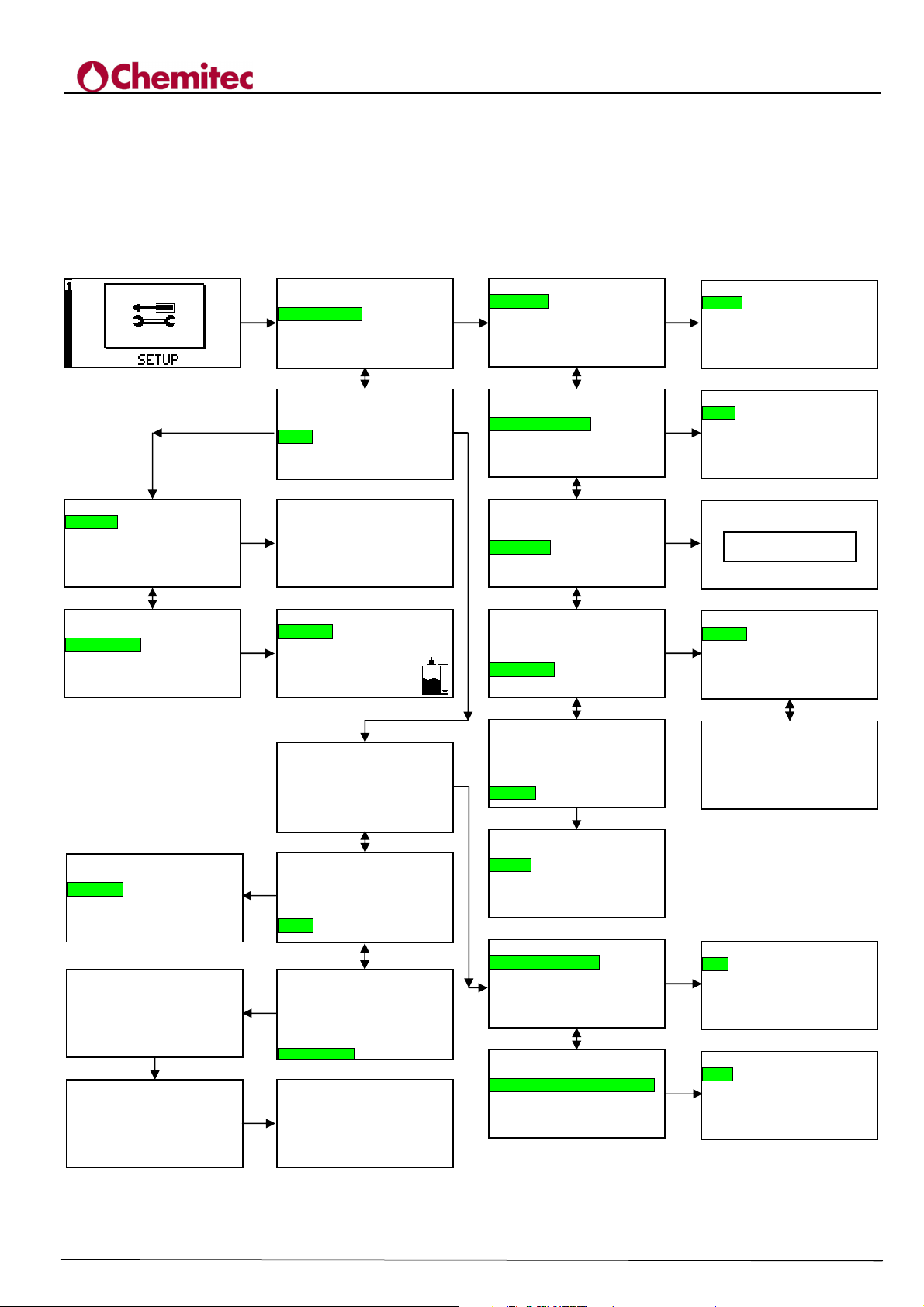
It is the second menu of the icon “SETUP” (see Fig. 7-3).
ENTER
1.0 SETUP
+
RELAYS
DOWN
SYSTEM SETUP
LEVEL
FLOW
TABLE
1.0 SETUP
RELAYS
ENTER
SYSTEM SETUP
LEVEL
FLOW
TABLE
1. 3 LEVEL
GENERAL
PARAMETERS
1. 31 GENERALE
Units cm
ENTER
Decimals 1
DOWNUP
1. 3 LEVEL
GENERAL
PARAMETERS
1. 32 LEVEL PARAM
h0 Dist 79.5 cm
ENTER
h max 29.0 cm
1.0 SETUP
RELAYS
SYSTEM SETUP
LEVEL
1.6 RESET SETUP
RESET?
1.5 TABLE
Points 0
1.0 SETUP
RELAYS
ENTER
SYSTEM SETUP
LEVEL
FLOW
TABLE
1.6 RESET SETUP
RESET?
1.6 RESET SETUP
RESET?
ENTER
1.0 SETUP
RELAYS
ENTER
SYSTEM SETUP
LEVEL
FLOW
TABLE
1.6 RESET SETUP
RESET?
ENTER
Default Setup loaded
1.2 SISTEM SET UP
DATE/TIME
ENTER
COMMUNICATIONS
LANGUAGE
PASSWORD
DISPLAY
DOWNUP
1.2 SISTEM SET UP
DATE/TIME
DOWN
COMMUNICATIONS
LANGUAGE
PASSWORD
DISPLAY
1.2 SISTEM SET UP
DATE/TIME
COMMUNICATIONS
LANGUAGE
PASSWORD
DISPLAY
1.2 SISTEM SET UP
DATE/TIME
COMMUNICATIONS
LANGUAGE
PASSWORD
DISPLAY
1.2 SISTEM SET UP
DATE/TIME
COMMUNICATIONS
LANGUAGE
ENTER
PASSWORD
DISPLAY
DOWNUP
1.25 DISPLAY
Contrast 69%
Back light. FIXED
DOWNUP
DOWNUP
DOWNUP
DOWNUP
ENTER
UP DOWN
Figure 7-3 "SETUP" Menu (part two)
1. 4 FLOW
GENERAL
PARAMETERS
DOWNUP
1. 4 FLOW
GENERAL
PARAMETERS
4204
TECHNICAL MANUAL P/N XXX-0000 Rev. 5 Ver. 3.4
1.21 DATE/TIME
Seconds 46
ENTER
Minutes 19
Hours 15
Day
13
Month 09
1.22 COMMUNICATIONS
Addres
ENTER
1
Baud rate 9600
FLOW METER
1.23 LANGUAGE
ENTER
ENGLISH
1.24 PASSWORD
STATUS
ENTER
NEW
DOWNENTER
Insert password
[
]
****
1.41 GENERIC FLOW
Units l/s
ENTER
Decimals 0
PMD RECTANG
Exponent 1.55
1.42 FLOW PARAM
q max 111 l/s
ENTER
Cut off 0 %
26
Page 31

4204
TECHNICAL MANUAL P/N XXX-0000 Rev. 5 Ver. 3.4
FLOW METER
The Set-Up system [1.2] defines the methods of communication of the System. Move to “SETUP”
[1.0] and select the “SYSTEM SETUP” [1.2]. The following items are available:
“DATE/TIME” [1.21]
“COMMUNICATIONS” [1.22]
“LANGUAGE” [1.23]
“PASSWORD” [1.24]
“DISPLAY” [1.25]
7.2.2.1
Date/Time [1.21]
The calendar time is expressed in:
“SECOND”
“MINUTES”
“HOURS”
“DAY”
“MONTH”
“YEAR”
The clock within the System is not synchronised to daylight time. Therefore the operator must
remember to modify it and check the archives in correspondence with the time change.
In order to set the data, follow the instructions indicated in point 7-1 i).
7.2.2.2 Communications [1.22]
It allows for the power unit to be connected within a telematic data transmission System.
Move to “SYSTEM SETUP” and select “COMMUNICATIONS”[1.22].
Follow the instructions indicated in paragraph 7-1 [1.2] and set the data as specified in point 7-1 i).
The fields that can be specified are the following:
“ADDRESS”
“BAUD RATE”
7.2.2.2.1 Address [segue 1.22]
An address value of between 0 - 99 can be set in steps of "1".
7.2.2.2.2 Baud rate[1.22]
The transmission speed of the data can be set by selecting one of the following values: 9600 –
19.200 – 38.400 bps
7.2.2.3 Language [1.23]
It allows for setting of the language used in the power unit, from a choice of:
“ITALIAN”
“ENGLISH”
For the selection, move to “SYSTEM SETUP”[1.2]; select “LANGUAGE”[1.23] and make
your choice (see paragraph 7-1 d), i).
7.2.2.4 Password [1.24]
Access to the functions of the power unit may be granted through the use of a Password. This
section of the programme defines the methods of activation and the methods of modification of the
password itself.
27
Page 32

The possible selections include:
“STATUS” [1.241]
“NEW” [1.242]
7.2.2.4.1 Status [1.241]
This function activates the password. The specific operative methods of this function include:
• In pos. “PASSWORD” [1.24], activate “STATUS”
• Insert the current “Password” and press “ENTER”
• The programme moves to a “STATUS PASSWORD” mode [1.241]. A rectangular appears in
the centre of the screen, indicating:
“DISABLE”
or
“ENABLE”
according to which one is active.
• Using the “UP” and “DOWN” keys select the condition requested and press “ENTER”.
The programme will return to the “PASSWORD” position [1.24], and will conclude the
operation.
4204
FLOW METER
TECHNICAL MANUAL P/N XXX-0000 Rev. 5 Ver. 3.4
7.2.2.4.2 New [1.242]
The programme allows for modifications to be made or the input of a password, as follows:
• In the “
PASSWORD
• Insert the existing password. If it has not been inserted before, the default value is “0”.
• The programme will move onto “NEW PASSWORD” [1.242]. A request for a "NEW
PASSWORD" will appear in the middle of the screen.
• Insert a new “PASSWORD”
[*****]
Numerical values between 1 ÷ 9999 may be inserted.
Press “ENTER”. The programme will return to the “PASSWORD” position and conclude the
operation.
If confirmed, when leaving the "SETUP" mode, the new “PASSWORD” is the operative one.
7.2.2.5 Display [1.25]
This function of the programme allows for definition of contrast and back light.
In order to activate it, move to “SYSTEM SETUP”; select “DISPLAY”; according to the contents
of paragraph 7-1 d), and operate as follows.
” position [1.24] select “NEW” [1.242]
7.2.2.5.1 Contrast
Contrast on the representation may vary between 0% and 100%, operating as specified in point 7-1
i). The standard conditions are between 87÷96%.
Contrast may be set even when the power unit is activated, as specified in paragraph 5-1.
7.2.2.5.2 Back light
The back light of the screen may be:
28
Page 33

“FIXED” it remains constantly active
“AUTO” it is activated when any test is pressed and is disabled after more than 15 seconds
if none of the keys are touched.
7.2.3 LEVEL [1.3]
This segment of the programme allows for the calculation System to acquire the parameters related
to positioning of the probe, with reference to the level (recess) of the fluid.
Move to “SETUP” [1.0] and select “LEVEL” [1.3](See Fig. 7.3).
The programme has two items, which are:
“GENERAL” [1.31]
“PARAMETER” [1.32]
7.2.3.1 Level Param[1.31]
This segment of the programme sets the metric units of measurement used for all remote
measurements.
Move to “LEVEL” [1.3]; select “GENERAL” [1.31]
Using the function “UNITS” the operator can ask the programme to represent the data in:
“M”
“cm”
“mm”
The ratio is created according to the contents of paragraph 7.1 i).
Using the function “DECIMAL”, the operator can define the number of decimals that follow the
unit. The maximum value that can be set is “3”.
It is important to remember that the maximum value set is a function of the unit of measurement.
The programme operates internally on a reference in "mm", therefore the maximum number of
decimals permitted is:
4204
FLOW METER
TECHNICAL MANUAL P/N XXX-0000 Rev. 5 Ver. 3.4
UNITS DECIMAL
m 3
cm 1
mm 0
7.2.3.2 Parameters [1.32]
Using the functions, the following should be inserted into the programme:
• the height of the probe compared with the corresponding point for flow"0"
For spout applications, the distance will be between the "face" of the transducer and the spout
threshold
For Venturi channel applications or similar, the distance will be between the "face" of the
transducer and the bottom of the channel.
• the maximum height of the water channel (hydraulic recess) at the maximum flow, compared
with point zero. ( This value should be calculated using the specific formula for the type of spout
or channel used)
Move to “LEVEL”[1.3]and select “PARAMETERS” [1.32]
The items that can be inserted are:
“h0 DIST”
“h. MAX”
29
Page 34

7.2.3.2.1 h 0 Dist
At this stage the metric value of the distance (in height) should be inserted between the position of
the probe and the level used as the "0" value of the recess. The maximum value that can be set is
5mm (corresponding to the maximum field of the probe)..
7.2.3.2.2 h max.
At this point the metric value of the distance between the value used as value "0" and the maximum
level that will be achieved by the hydraulic recess should be introduced.
The maximum value that can be set is 4.70 m. (Considering that a "DEAD ZONE" of 30cm is
located close to the probe).
7.2.4 FLOW [1.4]
This segment of the programme, accessible from the “SETUP [1.0]” icon, allows for the input
of the parameters related to the instant flow.
The items available are (see Fig. 7-3):
“GENERAL” [1.41]
“PARAMETER” [1.42]
4204
FLOW METER
TECHNICAL MANUAL P/N XXX-0000 Rev. 5 Ver. 3.4
7.2.4.1 Generic Flow [1.41]
The parameters related to the instant flow should be set here.
Move to “FLOW” [1.4] and select “GENERAL”[1.41].
The following fields are available:
“UNITS”
“DECIMALS”
“PMD”
“ESPONENT”
7.2.4.1.1 Units
It specifies the unit of measurement for the flow: mc/h or l/s
7.2.4.1.2 Decimal
It indicates the number of decimals with which the value of the flow is visualised: 0, 1, 2 or 3.
The maximum number of decimals permitted is a function of the flow (Q_Max); it may be re-set
automatically by the programme, if necessary.
7.2.4.1.3 PMD
The device type (channel or spout) that will be inserted at the bottom of the measuring probe should
be inserted here. Specific calculation formulas allow for the exact definition of the dimensions and
the distance at which the measuring probe should be positioned. In accordance with these
prescriptions during a plant engineering stage, it is possible to achieve the correct measurement of
the flow according to the variation in height of the recess. The following types are available:
• Rectang ("Francis" rectangular spout)
• Trapez (“Cipolletti” trapeze spout)
• Venturi (Venturi channel)
• Parshall (Parshall channel)
• Leopold (Leopold channel)
30
Page 35

• Stram. V (A triangular V "Thompson" spout)
• Other (a freely programmable exponent)
The last type (Other) refers to a non standard exponential device and therefore the exponent may be
freely programmed by the user.
7.2.4.1.4 Exponent
It defines the exponent used for calculations, related to the PMD selected. This field can only be
modified if PMD = OTHER has been selected: for standard PMD's it is set automatically and in
display only (this indicates the exponent value defined by the PMD itself).
7.2.4.2 Flow Param [1.42]
It allows for setting of the field of measurement of the flow.
Move to “FLOW” [1.4] and select “PARAMETERS”[1.42].
The following fields are available:
“Q MAX”
“CUT OFF”
They can be selected according to the contents of paragraph 7.1 i).
4204
FLOW METER
TECHNICAL MANUAL P/N XXX-0000 Rev. 5 Ver. 3.4
7.2.4.2.1 Q Max
In this field “Q MAX” the maximum value of the instant flow corresponding to the maximum
recess should be inserted (see paragraph 7.2.3.2.2. max h_) .
The maximum value that can be set is 9999 mc/h; if it is set as a unit of measurement “l/s”, the
maximum value will be 2777 l/s).
7.2.4.2.2 Cut off
The “CUT OFF” field specified the threshold (0-99% of instant flow) below which the volume
should not be counted.
7.2.5 TABLE [1.5]
Press ENTER to access to the “Points” menu.
If “Points”=0 the empirical function is not used (and the flow is calculated using the analytical
function); in this case in 1.32 LEVEL PARAM the “h.MAX” (maximum height) field is shown
and in 1.42 FLOW PARAM the “q.MAX” (flow value at h_max that defines the FS) field is
shown.
If “Points”=N (N between 1 and 130) the empirical function is used; in this case in 1.32 LEVEL
PARAM the “h.exp” field is shown and in 1.42 FLOW PARAM the “q.exp” field is shown;
the h_exp/q_exp parameters define the analytic part of the flow calculation (from h=0 to h=h_exp);
if h has a value between h_exp and h(N) the flow will be calculated with a linear interpolation of the
defined points. In this case the FS of the flow is defined by q(N) (the last point of the table).
If, for example, <Points>=3the first 3 points of the table can be edited (using the UP/DOWN keys):
h(1) is the height of the 1-st point
q(1) is the flow of the 1-st point
At h(3) (the very last point of this example) the h_max value is shown and at q(3) the q_max value
is shown: these are useful to remember that if the table is on, the FS are defined from the last point
of the table itself:
31
Page 36
4204
TECHNICAL MANUAL P/N XXX-0000 Rev. 5 Ver. 3.4
FLOW METER
+
q(3)=q_max
+
q_exp
+-----------------+---------------+-----------+---------------+
0 h_exp h(1) h(2) h(3)=h_max
If the table is off:
+
q_exp = q_max
+-----------------+
0 h_exp=h_max
Note that if in 1.41 GENERIC FLOW “PMD”=OTHER and “ESPONENT”=1.00 are set, the
analytic function is now a line from (0;0) to (h_max; q_max), so the function is now only tabular
with height values:
0, h_exp, h(1), h(2), ...
7.2.5.1 Set up for the “Bazin” type overflow
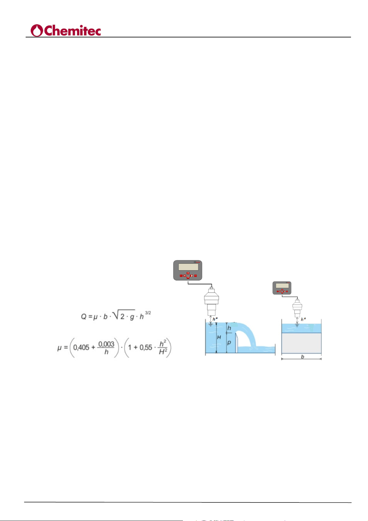
Figure 7-4 Scheme and calculation of the flow rate of a Bazin overflow
Q = [m3/s] Effluent flow rate by a thin wall (Bazin overflow)
b = [mm] Width of the thin wall section (weir)
p = [mm] Height of the thin wall section (weir)
H = [mm] Total height of the fluid upstream of the thin wall
h = [mm] Height of the fluid on the thin wall
h* = [mm] Height of the position of the probe. This must be at least 30cm higher than the
maximum swing h
µ = discharge coefficient
The 4204_Livello_Flow Rate device connected to a S425/C probe (ultrasound level probe), allows
to know the extent effluent by a thin wall or weir Bazin by updating firmware "Flow Meter 5.7”.
32
Page 37
TECHNICAL MANUAL P/N XXX-0000 Rev. 5 Ver. 3.4
bd)
c
f) e)
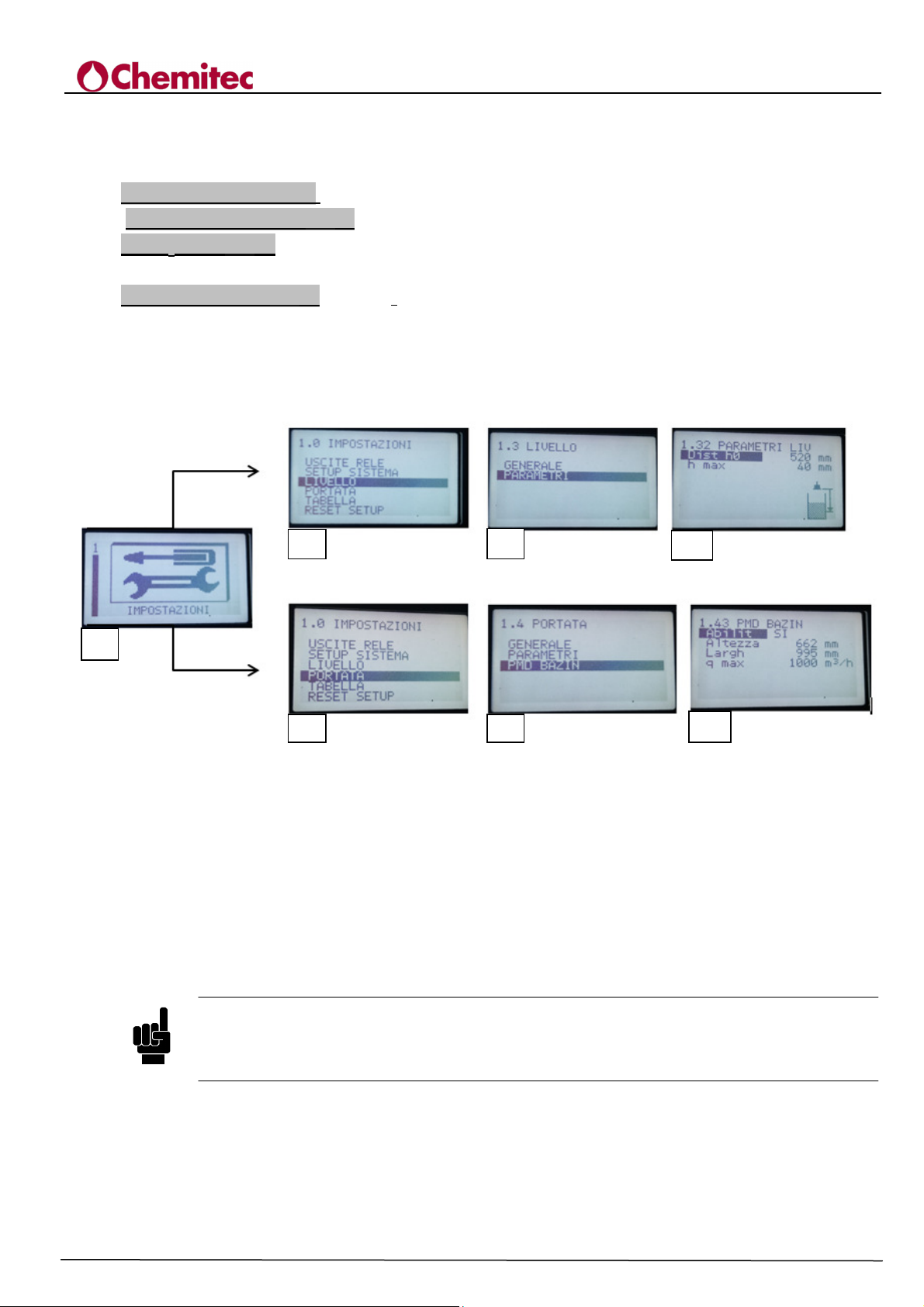
In order to set the flow measurement for a Bazin overflow you must enable this feature by 4204
instrument "Enable = Yes" (Figure 7-5) and set the following parameters specific to this overflow:
Bazin Height (Fig. 7-5 g) = mm (Height of the thin wall section).
Larghezza Bazin (Fig. 7-5 g)= mm (channel/wall width).
Dist h0 ( Fig. 7-5 d) = mm (this is the distance between the transducer face and the water head at
zero flow. The value in mm is given by h+h* (Fig. 7-4)
Qmax Bazin ( Fig. 7-5 g) = m^3/h (defines the maximum measurement threshold of flow rate by the
device, this value is only used to define the maximum value of the output current and the bargraph
on the display).
Follow this scheme to set these parameters:
4204
FLOW METER
a
Figure 7-5 Diagram for setting the parameters for a Bazin overflow
7.2.6 RESET SETUP [1.6]
Re-set of the set-up defines operation parameters at their default values. One single reset request is
carried out after which if YES is pressed, it will carry out the reset indicated by a message
"DEFAULT SETUP LOADED"; at this point all of the functions of the instrument are disabled
and must be programmed again.
The current set-up parameters, after a reset, are not lost altogether: if the operator is asked
whether or not he wants to save the parameters, if he decides not to save them, the original
parameters will be reloaded (the value they had when programming began).
g)
NOTE
33
Page 38
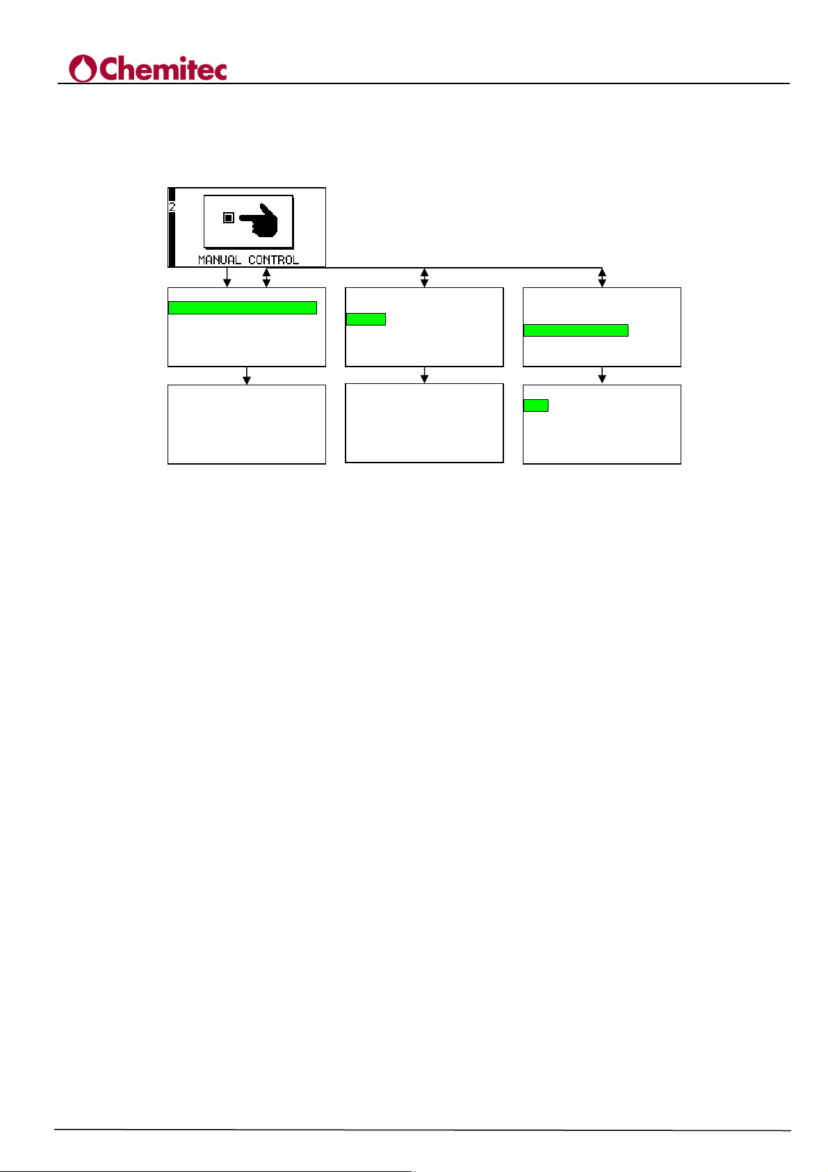
ANALOGUE OUTPUTS
ANALOGUE OUTPUTS
7.3 MANUAL CONTROL [2.0]
Item 2 of the main menu grants access to the test functions of the 4204Flow (see Fig. 7-6)
ENTER
UP/DOWN
2.0 MANUAL FUNC
LEVEL
RELAYS
2.1 TEST LEVEL
Distance 3059 mm
Temp 20 °C
UP/DOWN
2.0 MANUAL FUNC
LEVEL
RELAYS
ENTER
2.2 RELAYS
Relay 1 OFF
Relay 2 OFF
Relay 3 OFF
Relay 4 OFF
Relay 5 OFF
TECHNICAL MANUAL P/N XXX-0000 Rev. 5 Ver. 3.4
2.0 MANUAL FUNC
LEVEL
RELAYS
ANALOGUE OUTPUTS
ENTER
2.3 ANALOG OUTS
Out 1 0 mA
Out 2 0 mA
4204
FLOW METER
The functions available are:
“LEVEL”
“RELAYS”
“ANALOGUE OUTPUT”
They can be selected according to the contents of Par. 7.1 b).
7.3.1 TEST LEVEL [2.1]
The distance value is visualised (“DISTANCE”) and the temperature value (“TEMP”) of the
probe.
In the event of an error (communication, absence etc.) the following are visualised:
"??????"
7.3.2 RELAYS [2.2]
It performs a manual relay test, including control of their functionality.
In order to excite or de-excite a relay, turn the bar to its negative colour and press YES.
If the relay operates, it should change status every time it is pressed. When exiting, all of the relays
are automatically forced to OFF.
Figure 7-6 Menu “MANUAL CONTROL”
7.3.3 ANALOG OUTS [2.3]
It allows for out mA tests to be carried out. By pressing YES the value of the output current will
increase by 1 mA; when 20 mA are reached it will return to 0 mA.
34
Page 39
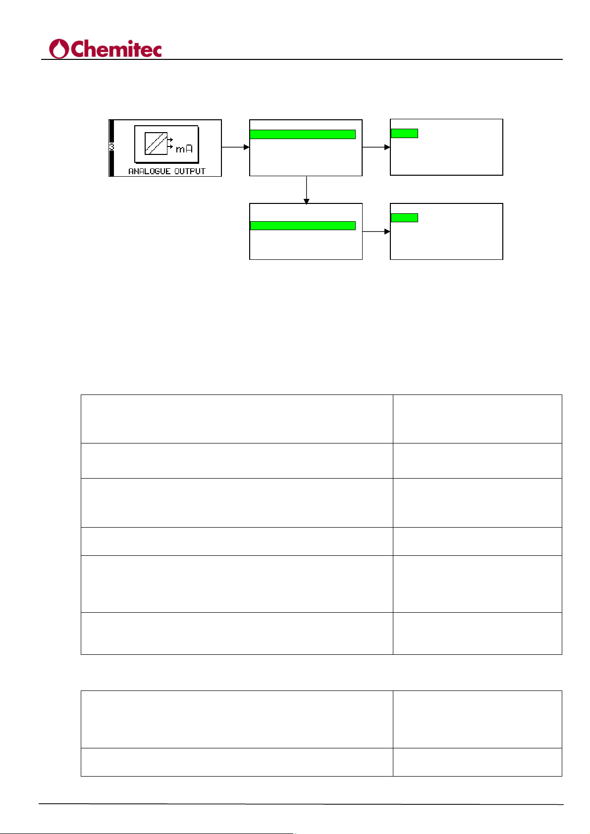
4204
TECHNICAL MANUAL P/N XXX-0000 Rev. 5 Ver. 3.4
FLOW METER
7.4 MA ANALOGUE OUTPUT [3.0]
Item 3 of the main menu allows for definition of the parameters in current (see Fig. 7-7).
ENTER
Figure 7-7 Menu “ANALOGUE OUTS”
The programme has two parameters:
“OUT 1”
“OUT 2”
They can be selected according to the contents of paragraph 7.1 b).
3.0 ANALOGUE OUTS
OUT 1
OUT 2
3.0 ANALOGUE OUTS
OUT 1
OUT 2
3.1 OUT 1
3.2 OUT 2
DOWN
Measure FLOW
ENTER
Type 0-20 mA
Inf lim 0 m3/h
Sup. lim 4700 m3/h
Namur NO
Measure FLOW
ENTER
Type 0-20 mA
Inf lim 0 m3/h
Sup. lim 4700 m3/h
Namur NO
7.4.1 OUT 1
It defines the outward parameters mA 1.
The “MEASURE” field selects the size to be used:
The field “TYPE” defines the output type: 0-20 mA or
The field “INF LIM” defines the value of the size at 0 or
4 mA if it has been chosen, respectively:
The field “SUP LIM” defines the value of the size to:
The field “NAMUR” is only important if:
and it undertakes the values “NO” or “YES”; in the second
case the current output is forced to:
Every time the field “FLOW” (par. 7.2.4.2.) is modified, all
of the default values are reset for:
“FLOW” or
“TEMPERAT.”
4-20 mA.
“TYPE”=0-20 mA or
“TYPE”=4-20 mA.
20 mA
“TYPE”=4-20 mA
2.40 mA in the
presence of an alarm
“INF LIM”
“SUP LIM”
7.4.2 OUT 2
It defines the output parameters mA 2.
The field “MEASURE” selects the size to be used:
“FLOW”
“TEMPERAT” or
“LEVEL” (recess).
The field “TYPE” defines the type of output: 0-20 mA or
4-20 mA.
35
Page 40
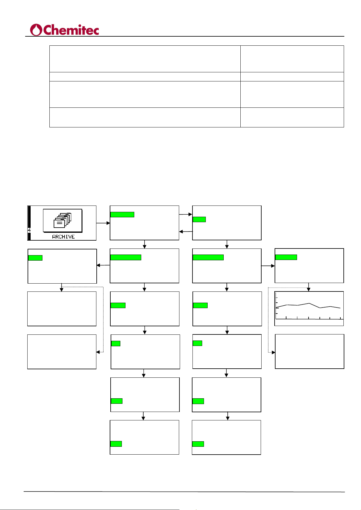
4204
ARE YOU SURE?
ARE YOU SURE?
TECHNICAL MANUAL P/N XXX-0000 Rev. 5 Ver. 3.4
FLOW METER
The field “INF LIM” defines the value of the size from 0
or 4 mA if it has been chosen, respectively:
The field “SUP LIM” defines the value of the size to: 20 mA
The field “NAMUR” is only important if:
and it undertakes the values “NO” or “YES”; in the
second case the current output is forced to:
Everytime the field “FLOW” (par. 7.2.4.2.) is modified, the
default values are automatically reset for:
7.5 ARCHIVE [4.0]
Item 4 of the main menu allows for display of the data included in the archive and in the flow
archive as well as their relative set-ups.
The following sub-menu is presented (see Figure 7-8):
“TOTALIZER” [4.1]
“FLOW” [4.2]
They can be selected according to the contents of paragraph 7.1 b).
4.11 VIEW DATA
Display
Date 10/04/06
ENTER
TOTALIZER (m3)
1 0 / 0 4/06 04 :1 4
0 0 0 3 4 8 0 . 9 4
1 0 / 0 4/06 21 :0 3
0 0 0 3 4 8 1 . 5 4
1 0 / 0 4/06 04 :2 4
NO MEASURE
7.5.1
ENTER
ENTER
TOTALIZER
FLOW
4.0 FILE
ENTER
4.1 TOTALIZER
DISPLAY DATA
SETUP
DOWN
4.1 TOTALIZER
DISPLAY DATA
SETUP
ENTER
4.12 TOTALIZER FILE
Step 0 min
Type
Occupancy 5 %
Reset >>>>
3 DOWN
4.12 TOTALIZER FILE
Step 0 min
Type
Occupancy 5 %
Reset >>>>
ENTER
4.12 TOTALIZER FILE
Step 0 min
Type
Occupancy 0 *
Reset >>>>
DOWN
TOTALIZER
FLOW
UP
ENTER
DISPLAY DATA
SETUP
DOWN
DISPLAY DATA
SETUP
ENTER
4.22 FLOW FILE
Step 0 min
Type
Occupancy 5 %
Reset
3 DOWN
4.22 FLOW FILE
Step 0 min
Type
Occupancy 5 %
Reset >>>>
ENTER
4.22 FLOW FILE
Step 0 min
Type
Occupancy 5 %
Reset >>>>
4.0 FILE
4.2 FLOW
4.2 FLOW
“TYPE”= 0-20 mA or
“TYPE” = 4-20 mA.
“TYPE”=4-20 mA
2.40 mA in the
presence of an alarm
“INF LIM”
“SUP LIM”
4.21 VIEW DATA
Display
ENTER
Interval 1 h
Date 10/04/06
ENTER
9999 m3/h
14:38 26/04/05 15:38
NO MEASURE
Figure 7-8 “ARCHIVE” menu
36
Page 41

TOTALIZER
The sub-menu “TOTALIZER” [4.1] carries out all operations related to the archive of the
totalizer and it includes the following items:
“DISPLAY DATA” [4.11]
“SETUP” [4.12]
They can be selected according to the contents of paragraph 7.1 b).
7.5.1.1 Display Data [4.11]
The field “DISPLAY DATA” [4.11 allows for programming of the methods of representation
of the data on the screen of the power unit.
The field “DATA” defines the day in which consultation of the archives will begin: 4 arrow keys are
available for editing: the “UP” and “DOWN” keys are used to scroll the days, the “RIGHT” and
“LEFT” keys are used to scroll 30 day periods. The current day is always shown at the beginning.
By pressing “VIEW DATA” the operator will move onto data display. Every screen shows 3
records: for each record the time (DD/MM/YY HH:MM) and value of the primary totalizer are
shown (during registration).
4204
FLOW METER
TECHNICAL MANUAL P/N XXX-0000 Rev. 5 Ver. 3.4
7.5.1.2 Totalizer File [4.12]
By selecting the item "SETUP" (4.12) from the "TOTALIZER” menu[4.1], the methods of
management of the System archive can be set.
The field “STEP” defines the registration step of the data that can be selected between 0’, 5’,
10’, 30’, 1 h, 2 h, 6 h, 12 h and 24 h; the value “0’” disables registrations.
The field “TYPE” defines the type of archive: linear (filling) or circular. In the first case the
registrations end when the archive is full: in the second case (circular) when the archive is full a
new registration overwrites the oldest one.
The item “OCCUPANCY” indicates the percentage of occupation of the memory.
The item “RESET” >>> allows for removal of all data in the archive: by pressing YES, the
operator is asked whether or not he is sure that he wants to carry out the reset, if he presses YES
again the archive will be emptied (at this point all data will be lost for good)
7.5.2 FLOW [4. 2]
The sub-menu “FLOW” [4.2] from the menu “ARCHIVE” [4.0] allows for all operations related to
the capacity archive to be carried out and includes the following items:
“DISPLAY DATE” [4.21]
“SETUP” [4.22]
7.5.2.1 Visualise Data [4.21]
The field “DATE” defines the date in which graphic consultation of the archives will begin: 4 arrow
keys are available for editing: the “UP” and “DOWN” keys are used to scroll the days, the “RIGHT”
and “LEFT” keys are used to scroll 30 day periods. The current date is always shown at the
beginning.
The field “INTERVAL” defines the interval of time for every single screen and can be
chosen between 1, 6 or 24 hours.
With the “DISPLAY” item, the operator will move onto data display. In correspondence with the
period of times, the date is indicated DD/MM/YY (in the middle) and the interval limits of display
in the format HH:MM. The value 00:00 on the right hand side refers to the following day: for
example if Interval = 6 h the measurements of the day 12/10/05 are shown in the 4 screens.:
37
Page 42
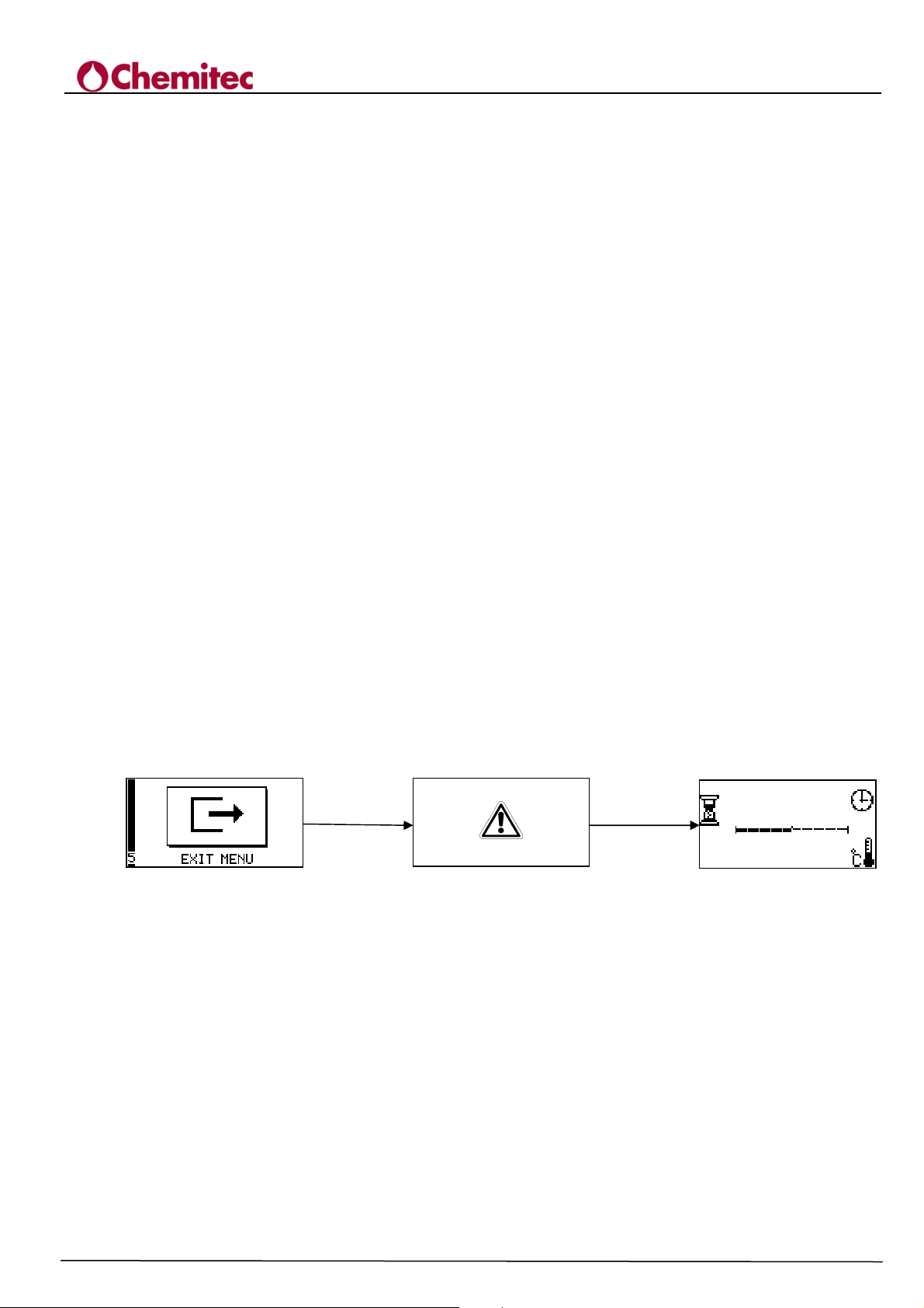
/s
19
“00:00 12/10/05 06:00” (1^ screen)
“06:00 12/10/05 12:00” (2^ screen)
“12:00 12/10/05 18:00” (3^ screen)
“18:00 12/10/05 00:00” (4^ screen)
Scrolling is carried out using the “LEFT” and “RIGHT” keys. In the top left hand corner the scale is
shown for flow (“Q_MAX”).
By pressing the ENTER key a window containing the maximum, average and minimum values of
the values in this interval of time are shown (this window does not appear if this interval of time
does not include any measurement): by pressing YES once again, the same screen will be visualised
using the values "MAX" and "MIN" as the limits.
7.5.2.2 Capacity Archive [4.22]
The field “STEP” defines the registration step of the data that can be selected between 0’, 1’, 2’, 5’,
10’, 15’, 20’, 30’ and 60’ minutes; the value “0’” disables registrations.
The field "TYPE" defines the type of archive: linear (filling) or circular. In the first case the
registrations end when the archive is full: in the second case (circular) when the archive is full a
new registration overwrites the oldest one.
The item “OCCUPANCY” indicates the percentage of occupation of the memory.
The item “RESET” >>> allows for removal of all data present in the archive: by pressing YES the
operator is asked whether or not he wants to carry out the reset, if YES is pressed again the archive
is emptied (at this point all data is lost once and for all).
4204
FLOW METER
TECHNICAL MANUAL P/N XXX-0000 Rev. 5 Ver. 3.4
7.6 EXIT MENU [5.0]
Item 5 (See figure 7-9) of the main menu allows the operator to exit the programming mode asking
him whether or not to save the settings. If the operator decides to save, a validity check of the
parameters will be carried out: this check is carried out as there are correlations between the values
assigned.
If values not permitted are included, an error message will appear. The following errors are
permitted:
“Err 3”: "UNDEFINED LOGIC "
“Err 5”: "OUTPUT LIMITS"
ENTER
Figure 7-9 Menu “EXIT MENU”
SAVE?
12/09/05 16:41
ESC/ENTER
0003496.54m3
0 l
It refers to the thresholds set for operation of
the relays as an alarm: the values Q ON and Q
OFF must be different.
mA 1" LIM INF < LIM SUP is requested for
the output in current 1
“Err 6”: "OUTPUT LIMITS mA 2"
LIM INF < LIM SUP is requested for the
output in current 2
“Err 10”: "FLOW (Q MAX)"
38
Not permitted q_max = 0
Page 43

4204
TECHNICAL MANUAL P/N XXX-0000 Rev. 5 Ver. 3.4
FLOW METER
“Err 18”: "MAX DISTANCE LEVEL 1"
A value of the distance of the recess of 0 > 5 m
has been registered .
“Err 19”: "RANGE LIV (h max)"
h_max value not permitted.
8 MAINTENANCE
8.1 SPECIAL ATTENTION FOR CRITICAL COMPONENTS
The instrument includes a LCD (Liquid Crystal Display) display that includes a bit of toxic agents.
In order to avoid the risk for personal damages and limit the environmental negative impact, it is
important to comply with the following instructions:
LCD display:
• The LCD display of the unit is fragile (glass) and must be carefully handled. For this reason,
during the transport or when it is not used, it is recommended to protect the device under its
original packaging.
• If the LCD glass breaks and some liquid comes out, pay attention not to come in contact with it.
Carefully wash in water for at least 15 minutes the body parts being in contact with the liquid.
Immediately contact a physician if after doing this operation, you feel any symptom.
39
Page 44

TECHNICAL MANUAL P/N XXX-0000 Rev. 5 Ver. 3.4
9 MODBUS PROTOCOL
Protocol type: serial modbus RTU
Speed: 9600, 19200, 38400 bps
This document contains:
Holding registers
User function for data download
---------------------------------------------- HOLDING REGISTERS
The MSB of the 16-bit value of a register is shown before the LSB
(MSB-1st encoding)
In the case of 32-bit integers, 2 contiguous registers are used. In the
following list if a parameter is associated with 2 contiguous registers means that
this parameter has a 32-bit value.
The registers are identified by its address (add):
reg add
0 Fw ver: MSB = higher N., LSB = lower N.
1 Device Id = 4204
6 Records currently in the local archive (max 29999)
7 State of I/O [1]
8 Level value (mm) [2]
10 Temperature in °C (with bias of 30000: e.g. 30023 means 23°C)
11 Measured distance from the probe (mm)
12-13 Current time of the RTC [3]
16-17 Time ON rele K1 (in minuti)
18-19 Time ON rele K2 (in minuti)
20-21 Time ON rele K3 (in minuti)
22-23 Time ON rele K4 (in minuti)
24-25 Time ON rele K5 (in minuti)
26 N. of commutations of relais K1
27 N. of commutations of relais K2
28 N. of commutations of relais K3
29 N. of commutations of relais K4
30 N. of commutations of relais K5
36-37 Time of last alarm[3]
38 Code of last alarm [4]
Note:
[1] You have the following correspondence:
bit 13 dig inp 5
bit 12 dig inp 4
bit 11 dig inp 3
bit 10 dig inp 2
bit 9 dig inp 1
4204
FLOW METER
40
Page 45

4204
FLOW METER
TECHNICAL MANUAL P/N XXX-0000 Rev. 5 Ver. 3.4
bit 5 rele K5
bit 4 rele K4
bit 3 rele K3
bit 2 rele K2
bit 1 rele K1
bit 0 rele allarme
[2] The value of the level is encoded with shift of 100000: for example, if the
registers 8-9 contain the value 112340, it means level = 12340 mm (in this example the register 8 contiains 1
and the register 9 contains 46804)
[3] These times are expressed as n. of seconds since 1/1/2000 0:00:00
[4] Code of the most recent alarm that has occurred, a zero value
means that no alarm was never registered.
----------------------------------------------------- DATA DOWNLOAD
Download of the data in the local store is done through the
function user-defined 66 (not editable)
The transfer starts with the following transiction:
(session opening, subfunct = 0xF0):
query (6 bytes):
pos bytes
0 1 Device address
1 1 function = 66
2 1 subfunction = 0xF0
3 1 REQ_CODE [1]
4 2 CRC
response (14 bytes):
pos bytes
0 1 Device address
1 1 function = 66
2 1 subfunction = 0xF0
3 1 0x00
4 1 ver fw higher n.
5 1 ver fw higher n.
6 2 Device ID = 4204
8 1 0x00
9 1 0x00
10 2 RECORDS [3]
12 2 CRC
Note:
[1] REQ_CODE must have 0 or 1 value.
[3] RECORDS is the total number of records that will be downloaded
during the session (this is the number when calling)
41
Page 46

TECHNICAL MANUAL P/N XXX-0000 Rev. 5 Ver. 3.4
The records are required with the following transaction
(reading of a record, subfunct = 0xF1):
query (6 bytes):
pos bytes
0 1 Device address
1 1 function = 66
2 1 subfunction = 0xF1
3 1 PACK_NUM [1]
4 2 CRC
response (114 bytes):
pos bytes
0 1 Device address
1 1 function = 66
2 1 subfunction = 0xF1
3 1 RECCOUNT [2]
4 12 Rec#1 [3]
16 12 Rec#2
28 12 Rec#3
40 12 Rec#4
52 12 Rec#5
64 12 Rec#6
76 12 Rec#7
88 12 Rec#8
100 12 Rec#9
112 2 CRC
Note:
[1] PACK_NUM must have 0 or 1 value
[2] RECCOUNT is the number of records currently in the response. If RECCOUNT = 9
9 records are present; if, for example, RECCOUNT = 3 only the first 3 records
are valid (rec#1, rec#2, rec#3)
[3] Every record is 12 bytes and has the following format:
bytes
4 Time: seconds since 1/1/2000 0:00:00 (integer unsigned
32-bit MSB-1st)
2 Not used
1 State of the relais
1 Not used
4 Level in mm: integer with sign 32-bit MSB-1st
Data download execution
The instrument maintains a pointer to the archive (current position): in a
session of data download the records are transferred from current position to the end of the archive.
4204
FLOW METER
42
Page 47

4204
FLOW METER
TECHNICAL MANUAL P/N XXX-0000 Rev. 5 Ver. 3.4
In the download session opening:
If REQ_CODE = 0 the current position won’t be edited, if REQ_CODE = 1 the current position will
become the start of the archive (in this case, the entire archive will be downloaded)
In the records request:
The first requested record must have PACK_NUM = 1, the second
PACK_NUM = 0, the third PACK_NUM = 1, and so on ... that is: to ask for the next record, the value of
PACK_NUM must change; if you send the query without changing the
value of PACK_NUM the device will transmit the same record.
Esempio di sessione di scarico dati
device master
<--------- subfun=0xF0 REQ_CODE=0 --------- [1]
--------------- subfun=0xF0 --------------> OK
<--------- subfun=0xF1 PACK_NUM=1 --------- request of first block of records [2]
---------- subfun=0xF1 RECCOUNT=9 --------> OK: 9 record received
<--------- subfun=0xF1 PACK_NUM=0 --------- request of following block of records
---------- subfun=0xF1 RECCOUNT=9 --------> OK: 9 record received
<--------- subfun=0xF1 PACK_NUM=1 --------- request of following block of records
---------- subfun=0xF1 RECCOUNT=9 --------> OK: 9 record received
<--------- subfun=0xF1 PACK_NUM=0 --------- request of following block of records
-------------------- ??? -----------------> ERR [3]
<--------- subfun=0xF1 PACK_NUM=0 --------- request of block retransmission [4]
---------- subfun=0xF1 RECCOUNT=9 --------> OK: 9 record received
<--------- subfun=0xF1 PACK_NUM=1 --------- richiesta blocco di records successivo
---------- subfun=0xF1 RECCOUNT=9 --------> OK: 9 record received
<--------- subfun=0xF1 PACK_NUM=0 --------- richiesta blocco di records successivo
---------- subfun=0xF1 RECCOUNT=7 --------> OK: 7 record received (end) [5]
Commenti:
[1] The session opens with REQ_CODE = 0, so the transfer starts
from the current position.
[2] The first requested block (after the session opening) must have PACK_NUM = 1
[3] No response received (timeout) or the response is faulted
[4] Since it was not received a valid response, a retransmission of the block is requested
by sending the query with the same value of PACK_NUM
[5] 7 records were received; these are the last records, because
RECCOUNT = 7 all the records have been transferred
and the session can be completed (the session could be ended when You receive a block with
RECCOUNT < 9).
In the given example, 5*9+7 = 52 records were transferred.
43
Page 48

10 WARRANTY
Chemitec s.r.l. will replace or repair at its own sole option, those parts that may eventually manifest
defects in manufacturing or operating, despite of a diligent and proper use by the customer.
The defective product, or considered such, must be sent free of charge to the Chemitec Factory, via
I.Newton 28, 50018 Scandicci, Florence (Italy) and will be returned, after the reparation, at
purchaser’s expense. In order to activate the warranty, a detailed written request should be sent to
Chemitec s.r.l., specifying failures or disruptions complained within 12 (twelve) months from the
date of installation with a maximum of 18 (eighteen) months from date of shipment.
Are excluded from the warranty, then at purchaser’s charge, the costs of performance of our staff for
operations offsite, except the hours of work. The travel’s time and expenses, meals, etc. will be
charged according to ANIE rates.
Components subject of natural wear and glass-parts are excluded from the warranty. The warranty
lapses only if the equipment were manipulated by someone not belonging to our company or
without our explicit authorization.
THE EQUIPMENT ‘S TESTING IS PERFORMED AT THE CHEMITEC SRL COMPANY OF
SCANDICCI (FI).
MODELLO/MODEL
NUMERO DI SERIE/SERIAL NUMBER
TESTING DATE
NOTE:
CHEMITEC SRL
____________________
4204
FLOW METER
TECHNICAL MANUAL P/N XXX-0000 Rev. 5 Ver. 3.4
44
Page 49
11 REQUEST FOR SERVICE
11.1 PROCEDURE FOR SERVICE REQUEST
In case of the instrument being damaged or in case of partial or wrong working that cannot be
solved by the ordinary maintenance operations described on this manual or on the attached
documents, we recommend to contact one of the CHEMITEC offices or branches or the nearer
authorized dealer / service centre.
CAUTION
If the instrument is damaged or starts wrong working, not in compliance with the instruction
of this use manual, in particular referring to the safety, IMMEDIATELY STOP USING the
instrument and contact the service dept. Never use the instrument till all the safety
requirement are checked and reset.
NOTE
In order to accelerate all the service starting procedures and to make the problem detection
easier by the qualified technical staff, please fill in the following form already from the first
phone call.
The instrument data can be kept from the relevant plate data.
4204
FLOW METER
TECHNICAL MANUAL P/N XXX-0000 Rev. 5 Ver. 3.4
REQUEST FOR SERVICE
Instrument/system name ................................................................................................
Code/catalogue number ..............................................................................................
Unit number (SN)..........................................................................................................
Present software version (Rel) .......................................................................................
11.2 MAIN CHEMITEC OFFICES
OPERATING OFFICES
CHEMITEC s.r.l.
Operating office:
Via Isaac Newton, 28
50018 Scandicci
FLORENCE
Tel. 0039 55 7576801 - Fax 0039 55 756697
E-mail [email protected]
Web site: www.chemitec.it
45
 Loading...