


CHEMINSTRUMENTS
HOT MELT DRAWDOWN COATER
MODEL HLCL-1000
OPERATING INSTRUCTIONS
PRODUCT DESCRIPTION ..................................................................................................2
UNPACKING ........................................................................................................................2
ASSEMBLY ..........................................................................................................................2
Key Components ........................................................................................................3
DIAGRAM ............................................................................................................................4
DIAGRAM ............................................................................................................................5
ASSEMBLY ..........................................................................................................................7
OPERATION .........................................................................................................................8
Theory of Operation ...................................................................................................8
Power Up ...................................................................................................................8
Controller Operation ..................................................................................................8
Coating Operation .....................................................................................................10
MAINTENANCE ..................................................................................................................11
Cleaning .....................................................................................................................11
Troubleshooting .........................................................................................................12
Thermocouple Connections .......................................................................................12
Heating Rod Connections ..........................................................................................13
Replacing the Relay ...................................................................................................14
WARRANTY ........................................................................................................................15
1

PRODUCT DESCRIPTION
Congratulations on the purchase of your new ChemInstruments Hot Melt
Coater/Laminator model HLCL-1000. The HLCL-1000 is a designed to produce coated samples
of hot melt adhesives, and then laminate a variety of foils, films, and papers. The HLCL-1000 is
designed to consistently coat and laminate on a lab scale with the following features:
• Brake unwind stands for both the coater and laminator
• Web alignment guides
• Precision ground coating bars
• Independently heated coating bars and reservoir
• Adjustable air pressure for changing laminating pressure
• Variable speed from 0.5 - 7.5 feet per minute (0.15 – 2.25 meters per minute)
UNPACKING
Upon receipt of your new HLCL-1000, check the unit for any damage that might have
occurred during shipment. The coating bars are wrapped to protect them during shipment.
Carefully remove the wrapping (DO NOT USE A KNIFE). If any damage occurred during
transit, notify the carrier immediately.
The shipping crate should contain the following:
• HLCL-1000
• Envelope containing manual and machine documentation
• Two brake unwind cores
• Set of Allen wrenches
• Bag containing:
o Two Teflon side dams
o Two thickness gauges
o Four machine feet & four screws
2

ASSEMBLY & INSTALATION
The HLCL-1000 weighs over 160 pounds; DO NOT attempt to move it by yourself.
Multiple people should always be used whenever the HLCL-1000 needs to be moved.
1. Remove the HLCL-1000 from the crate and set on a sturdy surface.
2. The feet on the bottom of the HLCL-1000 may be adjusted by turning clockwise or
counterclockwise. Adjust the feet until the unit is level.
3. Unwrap the two brake unwind cores and place them on the top of the unwind stands.
4. Place the two Teflon side dams in the reservoir.
OPTIONAL: The laminator portion of the HLCL-1000 can be removed from the unit and
placed further away from the coater if necessary. The laminator is held in place by four screws.
These screws are located on the bottom of the laminator and accessed through the top of the
laminator by removing the front and back guards. Each guard is held in place by two screws on
either side of the top of the guard.
1. Remove the screws and the guards to access the bottom of the laminator.
2. Once the guards are removed, you will expose the screws which mount the laminator to
the coater. Remove the screws. Store the screws in a safe place in case you wish to
reattach the laminator.
3. Remove the laminator from the coater.
4. Replace the guards on the laminator. The laminator should never be operated without
the guards in place.
5. The four extra feet included in with the HLCL-1000 are to be used on the bottom of the
laminator if it is separated from the coater. Using the included screws, mount one foot in
each corner of the laminator.
Assembly and installation diagram:
1. Brake unwind core (pictured with
roll of film)
2. Brake unwind stand
3. Reservoir for Teflon side dams
4. Brake unwind core (pictured with
roll of film)
5. Brake unwind stand
6. Guard
7. Screw securing guard
8. Screw securing guard
3
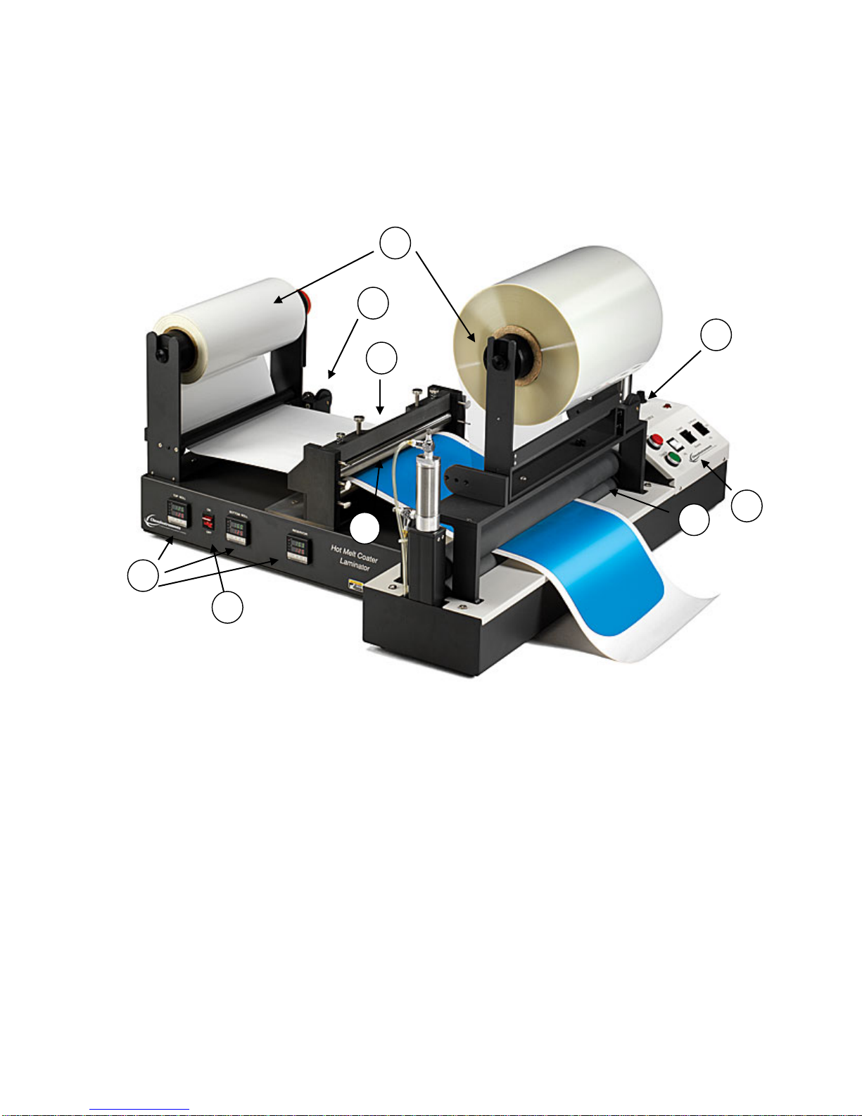
KEY COMPONENTS
1. Brake unwind stand (pictured with roll of film mounted)
2. Heating controllers
3. Coater ON/OFF switch
4. Coating head
5. Reservoir
6. Laminator controls
7. Laminating nip
8. Alignment guide
9. Alignment guide
4

OPERATION
1
The ChemInstruments HLCL-1000 allows you to produce lab scale simulations of
production processes. The HLCL-1000 has the ability to heat each coating bar and the reservoir
separately, which offers a greater range of control and diversity for your applications. The
reservoir is not designed to melt your coating, only to keep it at set temperature. The following is
a step by step process to create a finished product using the HLCL-1000.
5

The machine must be plugged in to the appropriate electrical and air source in order to
operate safely and properly.
1. Mount the desired substrate on the brake unwind cores and mount the brake unwind cores
on the unwind stands.
2. Thread substrate from the unwind stand at the left of the machine through the coating
head.
3. Set the coating head to the desired thickness of the coating you would like to produce.
4. Thread substrate from both unwind stands through the laminator nip.
5. Turn on the coater.
6. Program the desired temperature for the top coating bar, bottom coating bar, and
reservoir.
7. Turn on laminator. (ON/OFF switch is located on the back of the laminator next to the
plug.
8. Set laminator controls: speed, pressure, and direction.
9. Place Teflon side dams in reservoir to the desired width you would like to make the
coating, and pour the pre-heated coating into reservoir.
10. Close laminator nip to produce coating.
The HLCL-1000 should be run until the reservoir is empty and a coating is no longer being
produced. To stop the HLCL-1000, open the laminator nip. After the HLCL-1000 has cooled to
ambient temperature, disassemble and thoroughly clean the coating head.
6
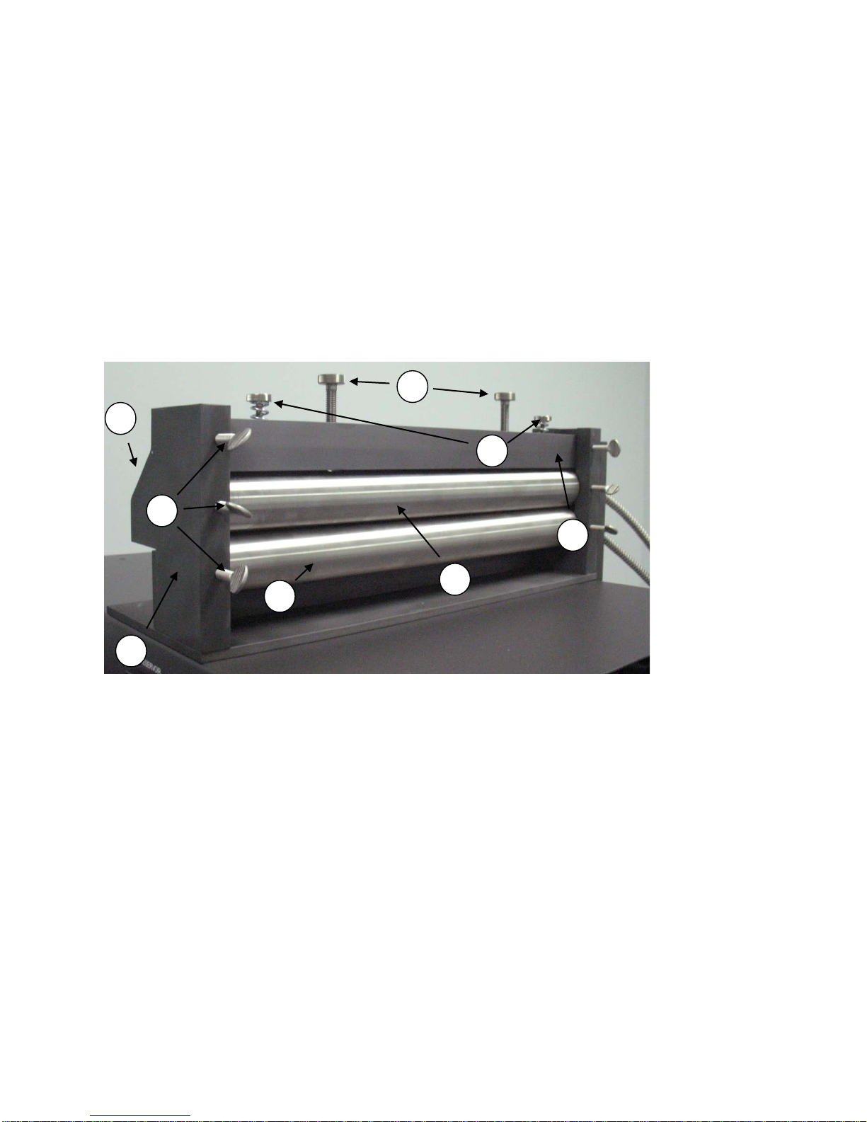
COATING HEAD
1. Thumbscrews
2. Gap Adjusting Screws
3. Tension Screws (These secure the top coating bar to the Crossbar. They are set in the
factory and do not require any adjustment)
4. Bottom Coating Bar
5. Top Coating Bar
6. Reservoir
7. Crossbar
8. Upright
SETTING COATING GAP
The follow directions will allow you to set the gap on the coating head to create a coating of a
desired thickness.
1. With the power off and the heating elements at room temperature, remove the heating
element from the reservoir. There is a plate that holds the heating elements in place which
must be removed. The plate is held in place by two screws. Remove the screws and pull
out the heating element.
2. Remove the reservoir.
3. Tighten the bottom thumbscrews on either side of the bottom coating bar.
7

4. Thread the substrate through the coating head in between of the top and bottom coating
bar.
5. Move the crossbar up so that the top of the crossbar is level with the uprights. Tighten the
top thumbscrews on either side of the crossbar to secure the crossbar.
6. Follow the steps bellow to set the gap between the top and bottom coating bars to the
desired thickness of coating you
would like to produce:
a. The gap adjusting screws can
be turned clockwise to lower
the top coating bar or
counter-clockwise to raise
the coating bar. Raise the top
coating bar to create a gap
between the top and bottom
coating bars.
b. The thickness gauges have multiple shims with their thickness stamped on them.
Find the desired shim and place each shim between the substrate and top coating
bar. Be sure to place them on opposite sides of the top of the substrate to insure a
uniform gap along the length of the substrate.
c. Turn the gap adjusting screws clockwise to lower the top coating bar on to the
shims of the thickness gauges.
d. Tighten the middle thumbscrews on either side of the top coating bar to secure it
in place, and remove the thickness gauges.
7. Replace the reservoir.
8. Replace the heating element in the reservoir and reattach the plate holding the heating
elements in the reservoir and coating bars.
RESERVOIR
The reservoir is located on the back of the coating head. The Teflon
dam inserts are placed in the reservoir as shown in the picture. The
dam inserts can be positioned anywhere in the reservoir to create the
specified width of the coating you would like to create.
8
CLEANING
The coating head can be disassembled for cleaning. *BE SURE THE MACHINE IS TURNED
OFF AND THE COATER IS AT ROOM TEMPERATURE*
1. Remove the plate on the right side of the machine that holds the heating elements in
place.
2. Remove the heating elements from the top and bottom coating bars and the
reservoir. *HEATING ELEMENTS MAY BE HOT EVEN IF COATING BARS ARE
ROOM TEMPERATURE*
3. Loosen the thumbscrews and remove the top and bottom coating bars and the reservoir.
4. The top and bottom coating bars can be cleaned with a soft cloth and solvent. Be sure to
only use a soft cloth that will not cause scratches to the coating bars.
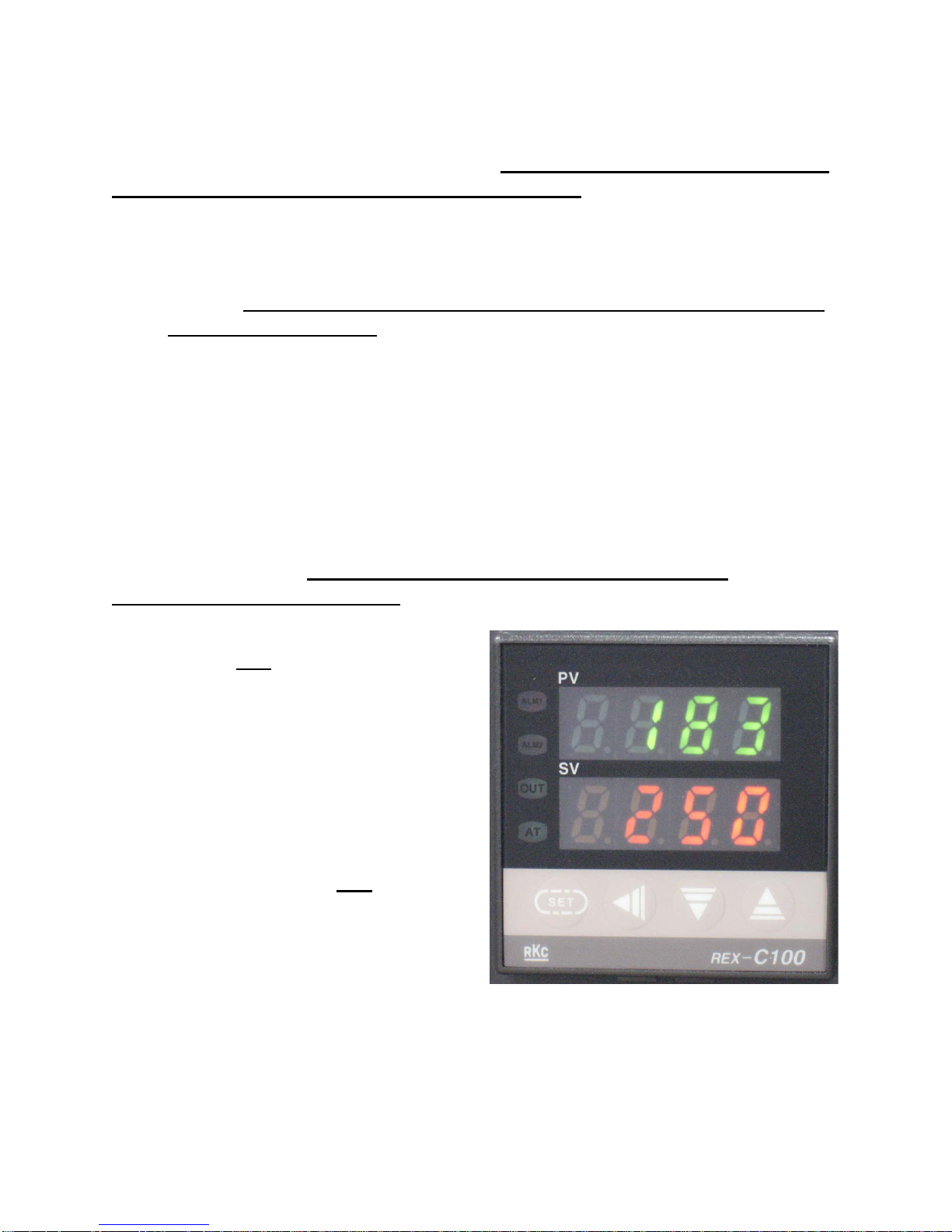
SETTING TEMPERATURE
Follow the instructions below to set the temperature for the top coating bar, bottom coating bar,
and reservoir. The temperature of the top coating bar, bottom coating bar, and reservoir are all
controlled independently. *BE SURE THE MACHINE IS PLUGGED INTO AN
APPROPRIATE POWER SOURCE*
1. Turn the machine on.
2. Push the SET button.
3. The temperature setting under SV will
start blinking.
4. Use the ˂ arrow to select which number
you would like to change.
5. Use the ˄ or ˅ buttons to select the
correct number for the temperature you
would like to set.
6. Once you have selected the correct
temperature, press the SET
button to set
the coater to the programmed
temperature.
9

MICROMETERS (optional)
The micrometers for the HLCL-1000 are optional. The
micrometers are mounted on crossbar of the coating
head (see diagram under COATING HEAD). The
micrometers allow a faster way to set the gap between
the top and bottom coating bar. Follow the directions
below to use the micrometers:
1. With the power off and the heating elements at
room temperature, remove the heating element
from the reservoir. There is a plate that holds the
heating elements in place which must be
removed. The plate is held in place by two screws. Remove the screws and pull out the
heating element.
2. Remove the reservoir.
3. Tighten the bottom thumbscrews on either side of the bottom coating bar.
4. Thread the substrate through the coating head in between of the top and bottom coating
bar.
5. Move the crossbar up so that the top of the crossbar is level with the uprights. Tighten the
top thumbscrews on either side of the crossbar to secure the crossbar.
6. Turn the gap adjusting screws clockwise to lower the top coating bar until it rests on the
substrate between the top and bottom coating bars.
7. Turn the micrometer dial so the hand points to zero.
8. Turn the gap adjusting screws counter-clockwise to raise the top coating bar. The
micrometers will indicate the gap created between the top and bottom coating bar caused
by raising the top coating bar. This gap will be thickness of the coating created.
9. Once the desired gap is reached, tighten the thumbscrews on either side of the top coating
bar to lock it in place.
10. Replace the reservoir.
11. Replace the heating element in the reservoir and reattach the plate holding the heating
elements in the reservoir and coating bars.
10

BRAKE UNWIND STANDS
The HLCL-1000 has two Brake Unwind Stands. One is located to the left of the coating head and
the other is located on top of the laminator. The Brake Unwind Stands allow for the substrate you
are coating or laminating with to be kept under tension during the coating/laminating process.
Tension is controlled by adding or relieving pressure to the friction plate.
1. 3 inch core.
2. Friction plate.
3. Set screw.
4. Nut.
5. Alignment wheel.
11

Follow the procedure below to load a substrate on the 3 inch core and adjust the amount of
friction on the brake system.
1. Slide a roll of material onto the 3 inch core. *CAUTION: the 3 inch core has knife
blades on it which are used to cut into the core of the roll of material and prevent it
from spinning. These knife blades are very sharp and can easily cut skin. Caution
should be taken when loading or unloading rolls of material to prevent injury.
ChemInstruments recommends wearing cutting gloves to protect hands during loading
and unloading.*
2. Place the core and friction brake assembly onto the Brake Unwind Stand.
3. Loosen the set screws sing an Allen wrench.
4. Turn the nut clockwise (add tension) or counter-clockwise (relieve tension).
5. Tighten the set screws using an Allen wrench.
6. Thread the substrate through the coating head or laminator.
7. Align the substrate through the coating head or laminator using the alignment wheel.
Turning the alignment wheel will move the Brake Unwind Stand clockwise or counterclockwise in order to align the substrate to travel straight through the coating head and
laminator nip.
12

LAMINATOR CONTROLS
13

1. Laminating Pressure Gauge: Displays the line pressure of the laminator. Pressure can be
adjusted using the pressure control located directly behind the laminating pressure gauge
on the back of the cabinet.
2. Emergency Stop button: Push the emergency stop button to cut off electricity to the
laminator and immediately open the laminating nip. Turn the button clockwise to
disengage and restore power to the laminator.
3. Speed control: Turn clockwise to increase speed or counter-clockwise to decrease speed
of laminator rolls.
4. Open Nip button: Push the open nip button to open the laminator nip.
5. Close Nip button: Push the close button to close the laminator nip.
6. Jog button: Push and hold the jog button to rotate the bottom the laminator roll. Release
the button to stop the bottom laminator roll from rotating.
7. Forward/Reverse button: Push the button to forward or reverse to control the direction the
bottom laminator roll will rotate.
8. Continuous/Stop/Job button: Push the button to continuous, stop, or jog to control the
bottom laminator rolls rotation. Continuous will allow the bottom roll to rotate
continuously. Stop will not allow the bottom roll to rotate. Jog will allow the bottom roll
to rotate when the jog button is pushed and held.
9. Pressure Regulator (not pictured): Turn the regulator knob counter-clockwise to increase
press and clockwise to decrease pressure at the laminator nip.
14

GAP ADJUSTERS (optional)
The optional Gap Adjusters are designed to help create a gap between the laminator’s top and
bottom rolls.
1. Gap Adjuster.
2. Guard.
3. Piston.
Follow the directions below to create a gap between the laminators top and bottom rolls:
1. Plug the laminator into the appropriate power and air supply.
2. Press the Open Nip button on the laminator controls to raise the laminator’s top roll.
3. Turn the Gap Adjusters (on both sides of the machine) counter-clockwise to loosen it.
4. Push the Close Nip button on the laminator controls.
5. The laminator’s top roll should come down and make contact with the bottom roll. If it
does not, repeat steps 3-5 until the top roll rests on the bottom roll.
6. Once the laminator’s top roll is resting on the bottom roll, turn the Gap Adjuster
clockwise to lower it until it makes contact with the Piston.
7. Push the Open Nip button on the laminator controls.
8. Turn the Gap Adjuster (on both sides of the machine) clockwise to lower it. The distance
the Gap Adjuster is lowered is the gap that will be created.
9. Push the Close Nip button on the laminator controls. There will now be a gap between
the laminator’s top and bottom rolls.
10. If the gap is not large enough, repeat steps 8-12 until the desired gap is reached.
11. If the gap is too large, repeat steps 8-12 but turn the cap and set screw counter-clockwise
instead of clockwise.
15

TROUBLESHOOTING (COATER)
PROBLEM
PROBABLE CAUSE
PROCEDURE
Power switch not lit
Machine not plugged in.
appropriate power supply.
Blown fuse.
Replace fuse.
Controller displays "LBA"
or disconnected.
control box. (See below A)
bad.
ChemInstruments.
increasing
Controller is bad.
ChemInstruments.
temperature not increasing
disconnected.
control box. (See Below - B)
Relay loose or bad.
necessary. (See below - C)
Controller is bad.
ChemInstruments.
Plug machine in
Green OUT lamp lit, PV not
increasing, but coating
head temperature is
Green OUT lamp lit, PV not
increasing, coating head
Thermocouple wires loose
Heating rod thermocouple
Heating rod wires loose or
Check connections inside
Replace heating rod. Call
Replace controller. Call
Check connections inside
Check relay and replace if
Replace controller. Call
UNPLUG THE MACHINE BEFORE ATTEMPTING MAINTENANCE PROCEDURES!
ELECTRIC SHOCK MAY OCCUR IF THE MACHINE IS PLUGGED IN!
A – Thermocouple connections:
1. Each heating rod cable contains four wires. The thermocouple wires are the small red and
white wires. The red wires should be connected to terminal 8 on the back of the Fenwal
heating controller.
2. The white wires should be connected to terminal 9. Check all six connections.
3. If “LBA” is displayed on the front of a Fenwal Temperature Controller, this means there
is a break in the thermocouple connection for that controller. If the above connections are
not bad, then the internal thermocouple must be bad, and the entire heating rod must be
replaced.
Note: The thermocouple wires are solid wire, making it easy to break or crack if bent too
severely. When checking these connections, be gentle with this wire.
16

B – Heating rod connections:
1. Each heating rod cable contains four wires. The two larger wires are hot and neutral. The
hot wires from each of the rods are connected to a red butt splice, which has a yellow
wire running to terminal 6 of the relay sockets.
2. The remaining neutral wire is connected to a blue butt splice, which has a white wire
running to terminal 7 of the relay sockets. This white wire is connected to all heating
rods, all controllers, and all relay sockets through a series of blue butt splices. If one of
these connections is loose, the rods will not heat up.
3. Make sure these connections are tight.
C – Replacing the relay:
1. The relays are the clear plastic boxes. First check to make sure each relay is firmly seated
by pushing down gently.
2. If the relay doesn’t move, continue with replacement. If it does move, firmly seat the
relay, reassemble the unit, and test.
3. To remove a relay, wiggle it in a circular motion while gently pulling it out of the socket.
4. Install a new relay by lining up the tab on the plastic post on the bottom of the relay with
the mating part in the socket. Push it firmly into the socket.
17

TROUBLESHOOTING (LAMINATOR)
PROBLEM
PROBABLE CAUSE
PROCEDURE
turn.
No power to motor.
power source.
Fuse blown.
necessary.
positions.
Check switches.
Motor shaft coupling loose.
below.
and material.
absent.
and bottom rolls.
up position.
No air pressure.
connection and setting.
restricted.
for proper operation.
lowered.
exhausted unevenly.
Check flow control valves.
Lamination has air bubbles.
being laminated.
pressure.
the center of the rolls.
back tension on laminate.
Air system leaks.
Tubing leak at connection.
tubing if necessary.
Pressure roll will not lower.
low.
to a minimum of 40 PSI.
closed.
Open flow control valves.
Bottom Drive Roll does not
Top laminating roll does
not turn with bottom roll
Top laminating roll does
not rise when switched to
One or more of the
switches is in the off
Contact between rolls is
Exhaust airflow is being
Check connections to
Check incoming power
fuse. Replace fuse if
Perform procedure A
Make sure the top roll is in
the down position. Increase
the pressure to assure
contact between the top
Check air connections and
air regulator for proper
Check flow control valves
Top roll moves unevenly
when being raised or
18
Air pressure is being
Air trapped between layers
Pressure regulator is set to
Flow control valves are
Check for proper air
Make sure material is in
Make sure you have proper
Check for leak in tubing at
connection. Replacing
Adjust pressure regulator

No air pressure.
Air supply not connected.
Connect machine to
valve is open.
compressed air line and
make sure flow control
A – Tightening the drive coupling:
1. Remove the four #6-32 screws holding the contorl panel in place.
2. Carefully lift the panel upward and toward the back of the cabinet. Be careful not to pull
any wires from their connection.
3. Locate the coupling joining the bottom roll shaft and the motor output shaft.
4. Line the coupling’s set screws up with the flats on the shafts of the roll and motor.
5. To prevent further slippage, remove the set screws and put a drop of removable Loctite
(or comparable product) on the set screws before replacing them in the coupling.
6. Using a 3/32 Allen wrench, tighten the two set screws.
7. Replace the control panel, being careful not to pull or pinch any of the wires.
19
 Loading...