

Page 1
3800 N. Mill Road
Vineland, NJ 08360
Phone: 800.843.1794
Fax: 800.922.4361
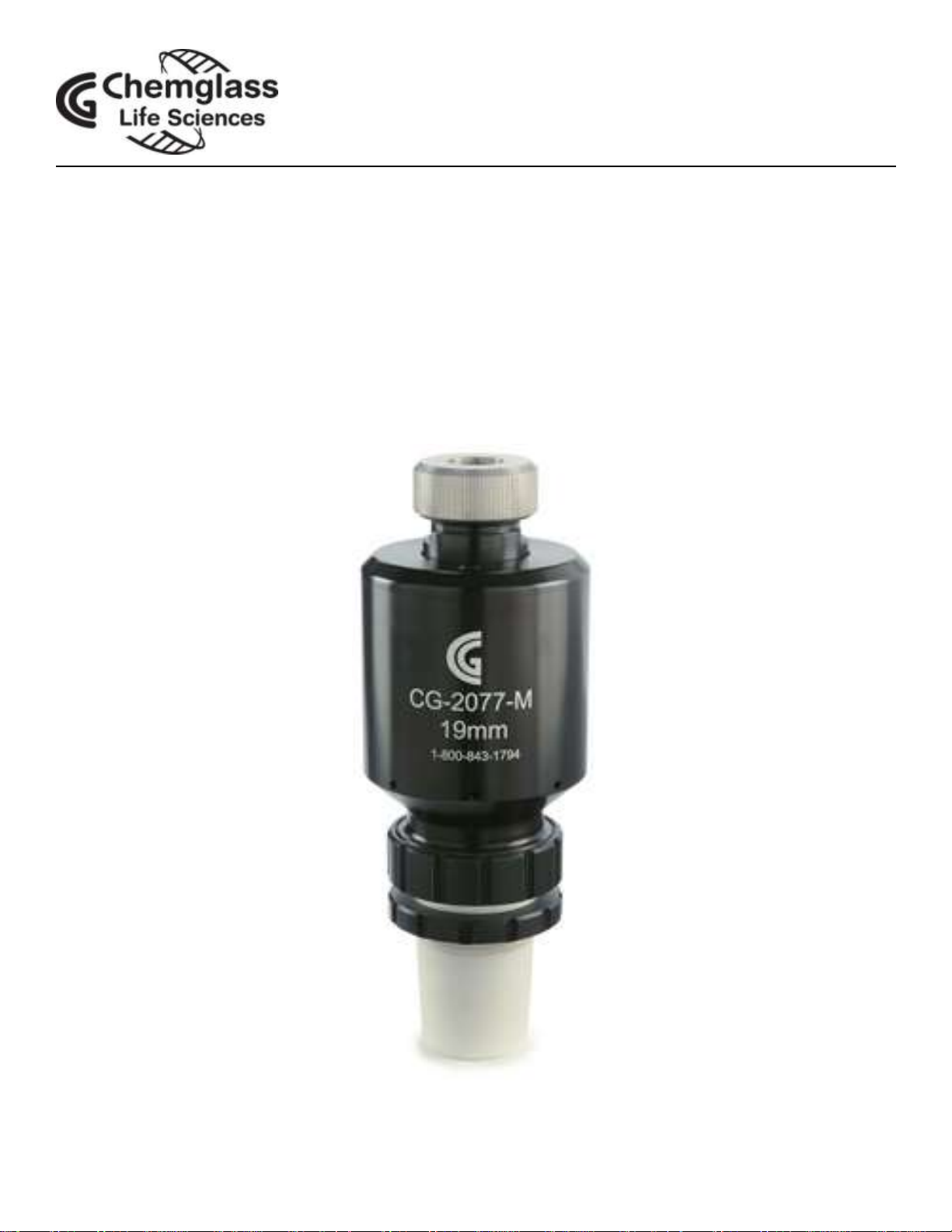
CG-2077-M
Mechanical Seal Stir Bearing
Instruction Manual
www.cglifesciences.com technical-service@cglifesciences.com
Page 2
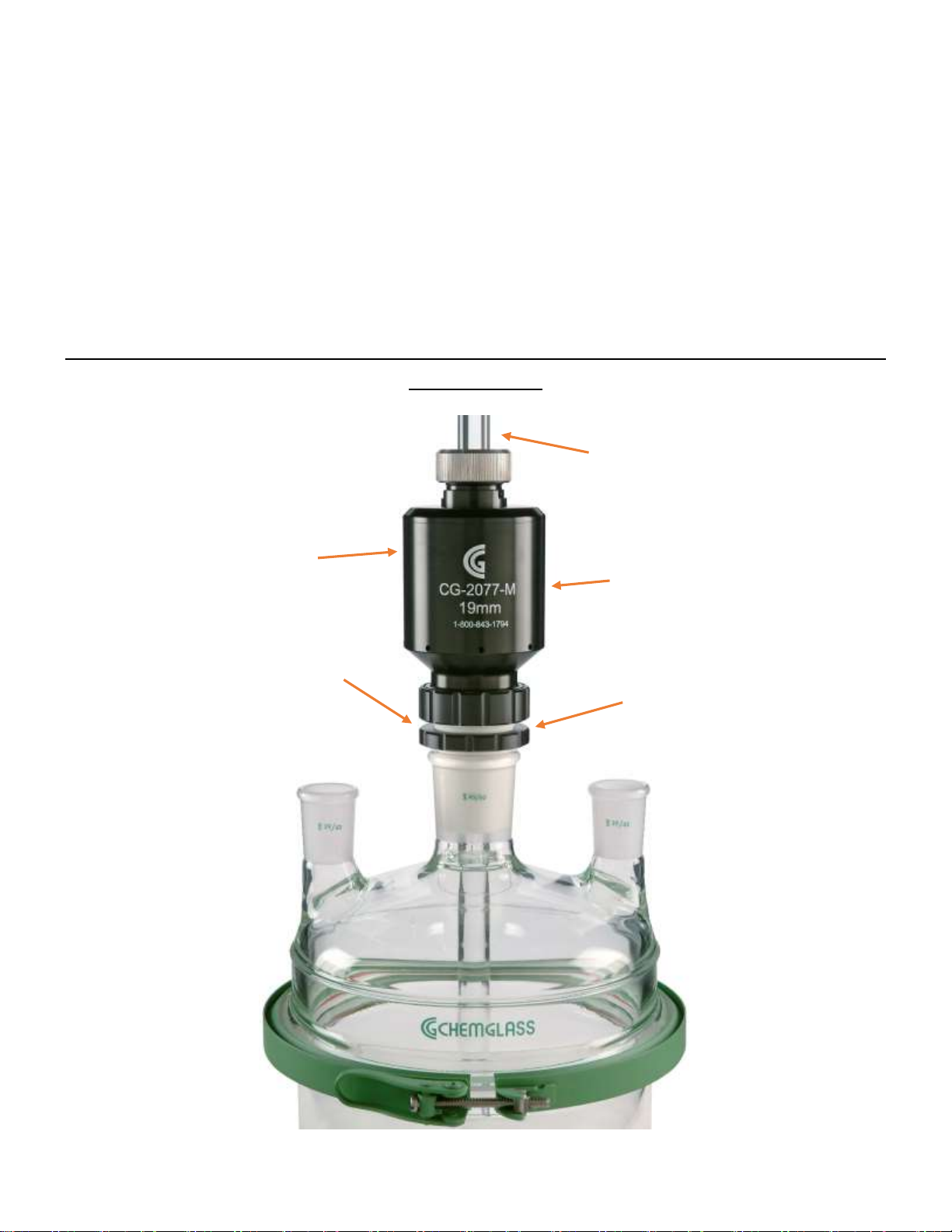
The Chemglass Mechanical Seal Stir Bearing is the only design in the
Bearing
Body
Glass Filled PTFE
Lower Joint
Adapter
Glass, PTFE, Stainless or
Hastelloy Stirrer Shaft
PTFE-Impregnated Hard-
Coat Finished Body
Nylon
Loosening Nut
market that will permit you to use your current glass, metal or PTFEcovered stir shaft. The design allows you to have the flexibility of
vertical adjustment and still choose your agitator diameter and style.
The bearing has a ferrule and locking nut to ensure that the seal rotates
properly, and is supplied complete with a gold plated wrench. Lower
joint adapters are supplied complete with perfluorinated o-rings and a
loosening nut.
Please note: bearing body and lower joint adapter must be ordered
separately.
www.cglifesciences.com technical-service@cglifesciences.com
Page 3

Please Note: The CG-2077-M Mechanical Seal Stir Bearing housing
and components should not be cleaned or submersed in solvents.
Bearing should be removed during cleaning to prevent solvent
exposure.
FEATURES:
• Dry running mechanical seal rotates with the shaft, providing for a
vacuum and pressure-tight seal.
• Unlike conventional PTFE bearings, Chemglass’ mechanical seal stir
bearing will not “flake”, contaminating your reaction.
• All seals are made using perfluorinated o-rings providing
outstanding resistance to the most aggressive chemicals.
• Bearing seals are rated up to 2,000rpm* with the seal life being
3,000 hours.
*Max RPM will depend on shaft and/or agitator type, along with
alignment of motor and coupling. Chemglass recommends a max of
500rpm with used with any glass vessel, lid or shaft. Longer length
stirrer shafts are required for use with CG-2077-M mechanical seal stir
bearings.
www.cglifesciences.com technical-service@cglifesciences.com
Page 4

Installation:
Step 1: Assemble reactor system, with vessel, lid and stirrer shaft
complete with agitators. Stirrer shaft should extend above the center
neck of the lid.
Step 2: Attach the lower PTFE joint adapter and remove the stainless
steel spindle nut and PTFE ferrule.
www.cglifesciences.com technical-service@cglifesciences.com
Page 5

Step 3: While holding the stirrer shaft, slide the mechanical seal stir
bearing over the end of the shaft (a small amount of mineral oil can
be applied to the stirrer shaft to help), through the bottom of the
bearing. Once the bearing is installed in the center neck, continue to
pull the shaft through the bearing and adjust to proper height.
SHAFT NOTES: BEARING IS DESIGNED FOR USE WITH ROUNDED OR
BEVELED SHAFT ENDS. DO NOT USE WITH FLAT ENDED SHAFTS.
www.cglifesciences.com technical-service@cglifesciences.com
Page 6

Step 4: Slide the PTFE ferrule (bevel down) over the shaft, followed by
the stainless steel spindle nut. Tighten the top spindle nut until the
spindle begins to rotate.
Step 5: Using the brass wrench, hand tighten the nut as necessary.
The nut will secure the ferrule to the shaft which will keep the shaft
from spinning in the spindle. Please note: if both the spindle and the
shaft rotate separately, then further tightening is needed. The stirrer
shaft and spindle should rotate simultaneously. Do Not Over Tighten.
www.cglifesciences.com technical-service@cglifesciences.com
Page 7

Operation: The mechanical seal stir bearing can be used for either
clockwise or counterclockwise operation. Due to the design of the
bearing, it will generate heat during normal use. The housing
temperature will rise approximately 40-50°C.
CAUTION: THE PURGE PORT MUST BE PLUGGED IF THE BEARING WILL
NOT BE CONNECTED TO NITROGEN.
Nitrogen Purge Set-Up: Our mechanical seal stir bearing can be used
with or without using a nitrogen purge. The bearing is included with
an “Instant Tube Fitting” already in place.
Step 1: Place one end of the black nylon tube into the “instant
tube fitting” (A).
Step 2: Insert the other end of the nylon tube into the “instant
tube fitting” (B). Tube will lock itself in place.
Step 3: Thread the nylon hose barb into the “instant tube fitting”
(B) until tight. Hose barb will accept 3/8”ID tubing, which will fit
most nitrogen ports in hoods.
www.cglifesciences.com technical-service@cglifesciences.com
Page 8

Set-Up Without Nitrogen Purge:
Step 1: Remove the “instant tube fitting” (A) using an Allen
wrench.
Step 2: Place a #007 Viton® o-ring onto a 10-32 x 3/16” screw.
Step 3: Thread screw into the mechanical seal stir bearing where
the “instant tube fitting” (A) was inserted.
Note: To remove the nylon tubing from the “instant tube fitting”,
simply push down on the o-ring of the fitting.
CAUTION: WHEN PLACING THE “INSTANT TUBE FITTING” (A) BACK INTO
THE MECHANICAL SEAL STIR BEARING, BE SURE NOT TO OVER TIGHTEN,
THREAD OF FITTING WILL SNAP OFF. DO NOT USE PURGE PORT AS A
VACUUM CONNECTION.
www.cglifesciences.com technical-service@cglifesciences.com
 Loading...