

Page 1
Safety requirements for electrical equipment for measurement, control and for laboratory use
IEC/EN 61010-1
Electrical equipment for laboratory use
UL 61010-1
General requirement - Canadian electrical code
CAN/CSA-C22.2 No.61010-1
www.cglifesciences.com
Phone: 1-800-843-1794
by VELP Scientifica
Instruction Manual
CG-1995-V-20
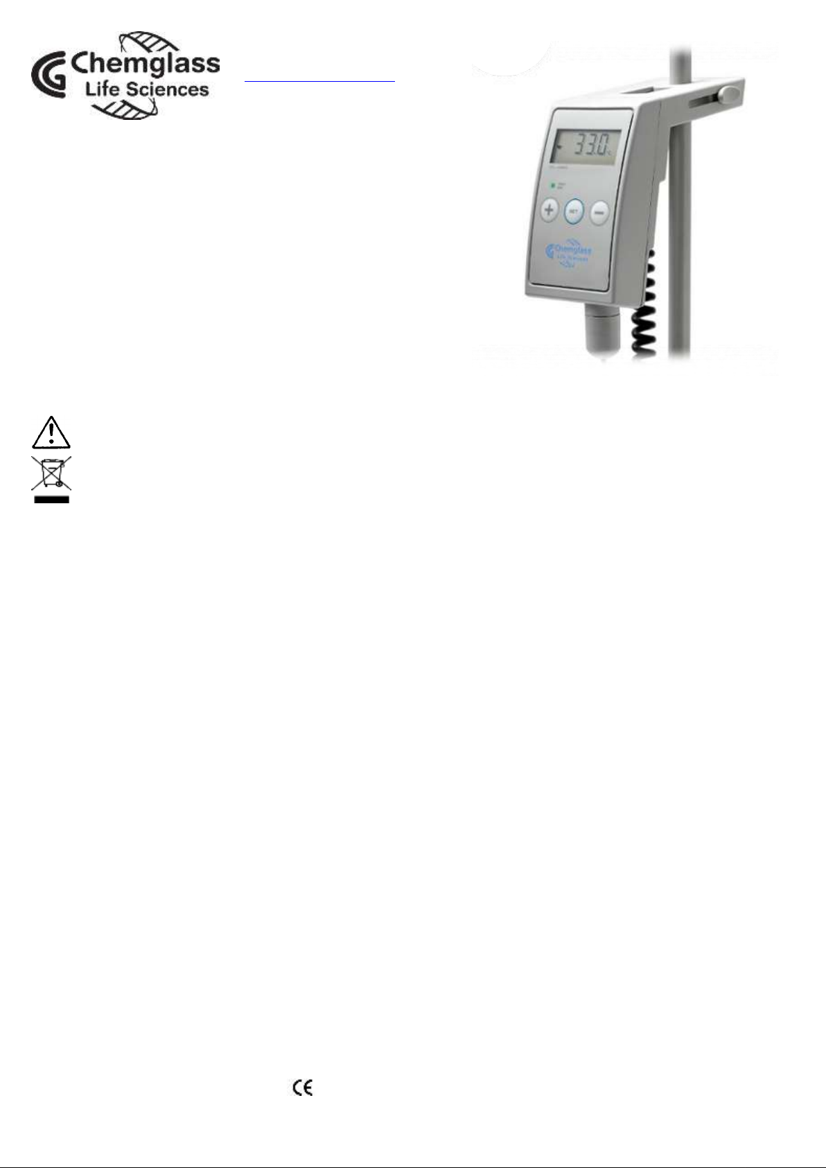
Digital Thermoregulator
General Information
This unit must be used for laboratory applications only.
The manufacturer declines all responsibility for any use of the unit that does not comply with these instructions.
This unit has been designed and manufactured in compliance with the following standards:
Before using the unit, please read the following instruction manual carefully.
Do not dispose of this equipment as urban waste, in accordance with EEC directive 2002/96/CE.
VELP reserves the right to modify the characteristics of its products with the aim to constantly improving their quality.
Contents
1. INTRODUCTION .............................................................................................................................................................. 2
2. ASSEMBLY AND INSTALLATION ................................................................................................................................... 2
2.1 CONNECTING THE PT100 PROBE ................................................................................................................................... 2
2.2 INSTALLING THE VTF .................................................................................................................................................... 2
2.3 USING THE VTF WITH HEATING MAGNETIC STIRRERS ...................................................................................................... 2
2.4 OTHER APPLICATIONS ................................................................................................................................................... 2
3. OPERATING CONTROLS ............................................................................................................................................... 2
3.1 SETTING THE WORKING TEMPERATURE .......................................................................................................................... 2
3.2 SETTING THE TIMER ...................................................................................................................................................... 3
3.3 TEMPERATURE ALIGNMENT ........................................................................................................................................... 3
3.4 UNIT OF MEASURE ........................................................................................................................................................ 3
3.5 SAFETY DEVICES AND ERROR SIGNALS .......................................................................................................................... 3
4. START-UP ....................................................................................................................................................................... 3
5. END-OF-WORK OPERATIONS ...................................................................................................................................... 3
6. MAINTENANCE ............................................................................................................................................................... 3
6.1 CLEANING .................................................................................................................................................................... 4
7. TECHNICAL DATA .......................................................................................................................................................... 4
8. WIRING DIAGRAM ......................................................................................................................................................... 4
9. ACCESSORIES ............................................................................................................................................................... 4
10. WARRANTY ..................................................................................................................................................................... 4
11. DECLARATION OF CONFORMITY ....................................................................................................................... 4
1
Page 2
°C
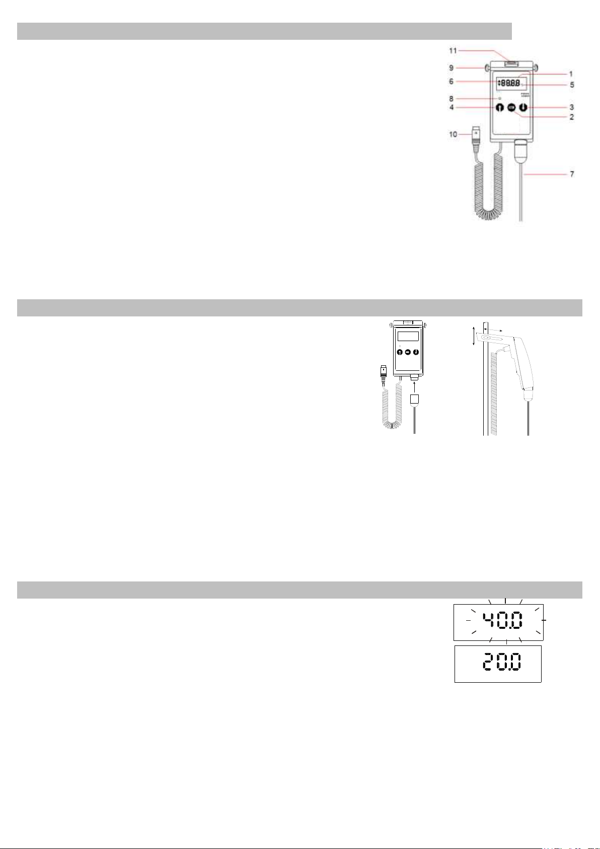
1. Introduction
1 Display 2 Set
3 Down arrow 4 Up arrow
5 Measurement unit 6 Timer display on
7 Temp. probe 8 Green “ON” led
9 Clamps 10 Plug
11 Sliding clamp
°C
Dig ita l Th er mo reg ula tor
VTF
FUZZY
LOGIC
Set
-10...+ 300°C
Fig. 2 Fig. 3
The Thermoregulator is ideal for many applications and meets the most demanding
requirements in terms of precision, reliability and flexibility of use thanks to the application of
Fuzzy Logic technology. The Fuzzy Logic electronic automatically adapts thermoregulation
to the varying factors such as power, load and thermal dispersion specific to each
application, optimizing both overheating and oscillations around the temperature set-point.
The accuracy and precision of thermoregulation at each end the scale and whatever the
volume being processed, is a fundamental characteristic of the Vertex.
WARNING: when the Thermoregulator is connected to an instrument other AREX, AREC.X
or PW10, please check the compatibility of the DIN 5 pole connector as illustrated in wiring
diagram in this manual.
NOTE: the most precise results are obtained measuring aqueous solutions temperature.
The microprocessor offers various other functions:
• a working time of up to 24 hours and 59 minutes can be set with automatic switch off;
• the maximum sample temperatures reached during the test can be recorded.
The structure is made of a non-scratch technopolymer resistant to chemical agents and Fig. 1
offers a high level of IP54.
The instrument has an in-built safety and control circuit which is constantly
active and shuts-down the thermoregulator immediately in the following
situations: the temperature probe is not connected; the temperature probe is
faulty (cut-off or short-circuited) and/or the temperature is out-of-range.
2. Assembly and installation
Check the integrity of the unit after unpacking. The box includes:
• Thermoregulator, with power cable
• Pt100 temperature probe • Instruction manual
2.1 Connecting the Pt100 probe
Connect the probe to the Thermoregulator as shown on Fig. 2.
2.2 Installing the VTF
The VTF has an innovative integrated system to simplify installation on the
support rod and facilitate the positioning of the Pt100 probe in the most
commonly used containers. The two clamps allow height-regulation whilst
a sliding clamp allows horizontal regulation (Fig. 3).
2.3 Using the VTF with heating magnetic stirrers
The power cable is suitable for connection to the most common heating magnetic stirrers with a dedicated socket for the
remote control of the stirrer such as AREX and AREC.X. The socket must supply a tension of between 9 and 16V DC. The
integrated installation system allows the instrument to be installed on support rods with a diameter between 10 and 13 mm.
2.4 Other applications
When using the thermoregulator for other applications bear in mind that the transistor output can take a maximum current of
50mA. Where power loads of up to 2200W are required the use of an external power relay is necessary (code A00000001,
PW10). For the thermoregulation of liquids that are not compatible with the construction material of the probe (stainless steel
AISI 316), the use of a glass-coated probe is recommended (code A00000003). When it is necessary to thermoregulate a
liquid that is not in close proximity to the VTF, a 1m probe extension cable is available (code A00000002).
3. Operating controls
Install the thermoregulator on the support rod and place the probe in the liquid to be
processed. To power the VTF plug the spiral cable into the dedicated socket on the heating
magnetic stirrer and turn the stirrer on. The display shows the software version after which it Fig. 4
flashes for approximately five seconds showing the last temperature Set Point used (Fig. 4).
The current Pt100 probe temperature reading is then displayed on the main window.
Thermoregulation starts automatically based on the last temperature Set Point used (Fig. 5). Fig. 5
NOTE: the magnetic stirrer always exercises primary control of the heating plate temperature. To control the heating plate
temperature using the VTF thermoregulator, set the magnetic stirrer temperature to maximum. The magnetic stirrer
temperature control can also be used as a safety thermostat since the heating plate will not exceed the temperature set on
the stirrer. In this case, longer heating time will be necessary in order for the sample to reach the VTF set point temperature.
3.1 Setting the working temperature
From the main window, press “SET”. The set-up window is displayed (Fig. 4).
Set Point Temperature From -10 to +300 °C Default value: 40 °C
With the display is flashing use “↑” and “↓” to select the temperature required. The temperature setting is saved when no
keys are touched for approx. 5 seconds (Fig. 5).
2
Page 3

If no key is pressed for approx. 5 seconds when the set-up window is flashing, the value shown on the display is
°C
°C
automatically saved. After 5 seconds the VTF will evaluate the temperature reading of the probe immersed in the liquid and
will proceed to thermoregulate the liquid to the temperature selected.
NOTE: to display the maximum temperature reached since the instrument was turned on, with the main window displayed
keep “↑” pressed. The maximum temperature reached is deleted from the memory every time the instrument is turned off.
3.2 Setting the timer
From the main window press “SET” twice to display the working time.
Working time From 00:00 to 24:59 (h:min.) Default value: 0:00 (Fig. 6) Fig. 6
With the display flashing use “↑” and “↓” to select the working time required.
To switch from hours to minutes press “SET” once or simply wait 4 seconds (Fig. 7).
Fig. 7
With the display flashing use “↑” and “↓” to select the working time required.
The value is saved when no keys are touched for approx. 5 seconds. If no key is pressed for
5 seconds the display returns the main window and the previously displayed value is saved.
Count-down starts the moment the working time has been saved. The alternate flashing of Fig. 8
the two arrows to the left of the display indicates that the VTF is running in timer-mode (Fig. 8).
At the end of the working time the instrument automatically turns off the thermoregulation, and the display shows “End”.
To return to the main window in order to start new work-cycle, press “SET”. Working time will return to the default value of
0:00 and the maximum temperature reached can be viewed by pressing “↑”. Working time can be changed when VTF is in
use even if the instrument is running in timer-mode. If working time is set to 0:00 the instrument will run in continuous mode.
NOTE: to display the time left, with the main window displayed keep “↓” pressed.
3.3 Temperature alignment
The micro-chip carries out automatic probe calibration therefore a probe calibration procedure is unnecessary.
Nevertheless, an offset value of from - 9.9 to + 9.9 °C can be set.
Temperature alignment From - 9.9 to + 9.9 °C Default value 0.0 °C
From - 17 to + 17 °F 0.0 °F
Turn the instrument on by keeping “SET” and “↓” pressed.
Use “↑” and “↓” to modify the “Temperature alignment” parameters (Fig. 9). Fig. 9
If no key is pressed for 5 seconds the display shows the software version and the last set point value.
If no key is pressed for a further 5 seconds the display shows the probe temperature reading and saves the value.
3.4 Unit of measure
Turn the instrument on by keeping “SET” and “↓” pressed. Use “↑” and “↓” to modify the “Unit of measure”.
If no key is pressed for 5 seconds the display shows the software version and the last set point value. If no key is pressed
for a further 5 seconds the display shows the probe temperature reading in the new unit of measure and saves the value.
3.5 Safety devices and error signals
The instrument has an in-built safety and control circuit which is constantly active and shuts-down the VTF in case of:
• unconnected probe • faulty probe (cut-off or short circuited) • temperature out of range (- 10…+300 °C)
Thermoregulation stops and the error message “Err” appears on the display.
To reset the thermoregulator turn it off and on again after having found and removed the cause of the alarm.
4. Start-up
• Install VTF on the support rod and immerse the probe by 15mm, making sure it does not get in contact with the container;
• Make sure the magnetic stirrer is turned on;
• Power VTF by plugging the spiral cable into the dedicated socket on the heating magnetic stirrer;
• Set the magnetic stirrrer temperature to maximum;
• Select the temperature and the working time required;
• To optimize thermoregulation and improve temperature homogeneity, stir the sample gently but continuously.
WARNING
• If working with set points near the evaporation temperature, the probe has to be immersed by 10mm throughout the cycle;
• The sample being processed is subject to evaporation and for this reason it may not reach the temperature selected.
5. End-of-work operations
To interrupt thermoregulation and leave the VTF thermoregulator powered, turn off heating plate using the knob on the
magnetic stirrer. In this way heating stops but the VTF continues to display the temperature. If the timer has been set, the
VTF will automatically stop at the end of the set time and the display will show “End”. To reactivate thermoregulation press
“SET”. At the end of the process, if the VTF has to be left connected to the magnetic stirrer, turn the stirrer off.
6. Maintenance
No routine or extraordinary maintenance is necessary apart from periodically cleaning the unit as described in this manual.
In compliance with the product guarantee law, repairs to our units must be carried out in our factory, unless previously
agreed otherwise with local distributors. The instrument must be transported in its original packaging and any indications
present on the original packaging must be followed (e.g. palletized).
3
Page 4

6.1 Cleaning
Disconnect the unit from the power supply and use a cloth dampened with a mild, non-flammable detergent.
7. Technical data
Power supply V cc 9÷15
Dimensions mm (WxHxD) 75x145x120
Weight Kg 0.250
Display 4 digit LCD, Multi function
Type of thermoregulation Fuzzy Logic
Connector 5 pole 270° DIN
Level of electrical protection CEI EN60529 IP54
Temperature range °C 0…+50
Storage temperature range °C - 10…+ 60
Max. humidity % 90%
Temperature settings (intervals) °C / °F - 10…+ 300 / 14…572 (1 / 1)
Resolution (precision) °C / °F 0.2 / 1 (± 0.5 / ± 0.9)
Working time settings h:min From 0:00 to 24:59
Continuous mode, remaining time reading Possible
Type of probe Pt100, 250 mm lenght
Probe speed τ90% sec 5
Immersion depth mm 15 minimum
8. Wiring diagram
1. Pt100 Probe
2. Electronic board
3. Plug DIN 5 poles
9. Accessories
Please contact Chemglass Life Sciences for more details about accessories.
www.cglifesciences.com Phone: 1-800-843-1794
10. Warranty
The unit is guaranteed against production defects for 25 months from our invoice date.
In accordance with this guarantee Chemglass Life Sciences undertakes to repair any units resulting as faulty due to the
quality of the materials used or poor workmanship.
Units rendered faulty due to inexpert handling/use or carelessness will not be replaced or repaired under warranty.
Exclusions:
The guarantee will be considered null and void for faults resulting from:
- inexperience and carelessness of the operator
- repairs, maintenance or replacement of parts carried out by personnel or Companies not authorized by the manufacturer
- use of the instrument that does not comply to the instructions/recommendations given in the present operating manual
- use of non-original spare parts.
11. Declaration of conformity
We, the manufacturer VELP Scientifica, under our responsibility declare that the product is manufactured in conformity with
the following standards:
EN 61010-1 (2001) EN 61326-1 (2006) 2011/65/EU (RoHS) 2002/96/CE (RAEE)
and satisfies the essential requirements of the following directives:
- Machinery directive 2006/42/EC
- Low voltage directive 2006/95/EC
- Electromagnetic compatibility directive 2004/108/EC
- plus modifications
4
 Loading...