

Chemglass AF-0349 User Manual
OWNER’S MANUAL
FOR
DIRECTORR® DIRECT-DRIVE VACUUM
PUMP MODELS:
8905
8907
8912
8917
8920
8925
WARNING
Do not block the exhaust port. Pressure will build up with the
potential of oil case bursting with possible injury to personnel.
WARNING
Pumps being run continuously above 1 torr should use an
exhaust oil recycler.
WARNING
Pumps not recommended for filtration, aspiration or drying
electrophoresis gels.
Welch Rietschle Thomas
7301 North Central Avenue
Skokie, IL 60077
Phone: (847) 676-8800
Fax (847) 677-8606 (Technical Support)
Fax (920) 451-4397 (Ordering)
E-Mail: welchvacuum@thomasind.com Part No. 67-1483R1.7
Web-Page: www.welchvacuum.com Printed in USA
For outside U.S. and Canada, contact your local
Rietschle Thomas sales office, see back page
INSTRUCTION
WARNING AND CAUTION
PLEASE READ BEFORE OPERATION
While reading your manual, please pay close attention to areas labeled:
WARNING AND CAUTION.
The description of each is found below.
WARNING
Warnings are given where failure to observe instruction could result in
injury or death to people.
CAUTION
Cautions are found where failure to observe the instruction could result
in damage to the equipment, associated equipment and process.
These units confirm to the SI International system of units of measurement.
The following symbols (with recommendation of IEC1010 ) of warning will be found on the pump.
Caution - refer to accompanying documents
Caution - risk of electrical shock
Caution - hot surface
WARNING
Motor includes a self resetting thermal cutout and the pump could
restart without actuation under fault condition.
2

TABLE OF CONTENTS
Section 01 - Installation
1.01 Unpacking
1.02 Pump Mounting
1.03 Pump Location / Environmental Conditions
1.04 Exhaust Provisions
1.05 Electric Power
1.06 Vacuum Connections
1.07 Vacuum Gauges
1.08 Vacuum Pump Oil
Section 02 - Pump Features & Principles of Operation
2.01 General Description
2.02 Principles of Vacuum Pump Operation
2.03 Effects of Continued Pressure Reduction
2.04 Ultimate Pressure
2.05 Pump Mechanism Description
2.06 Intake Anti-Suckback Protection
2.07 Pump Lubrication
2.08 Exhaust Filter
2.09 Gas Ballast Valve
2.10 UNIBARBTM Intake Fitting
Section 03 - Specifications
3.01 Specification Chart
Section 04 - Motor Power Specifications / Features
4.01 Motor Specification Chart
4.02 Changing the Voltage Settings for Global Motor Option on “A”-Models
4.03 Changing the Voltage Settings for Global Motor Option on “C”-Models
4.04 Changing the Voltage Settings on “A”-Models
4.05 Other Electrical Configurations
4.06 Explosion Proof Pumps
Section 05 - Operation
5.01 Starting Procedure
5.02 High Pressure Operation
5.03 Shutdown Procedures
3

Section 06 - Maintenance
6.01 Vacuum Problems
6.02 Oil Change
6.03 Developing a Maintenance Schedule
6.04 Lip Seal / Gasket Change
Section 07 - Troubleshooting
7.01 Leak Detection
7.02 Troubleshooting Guide
Section 08 - Repair Kits
8.01 Shaft Seal Replacement
8.02 Minor Repair Kits
8.03 Major Factory Repair
TABLE OF CONTENTS
Section 09 - Accessories
9.01 Pump Oil
9.02 Exhaust Filters
Section 10 - Dimensional Drawings / Speed Curves
10.01 Pumping Speed Curves
10.02 Dimensional Drawings
10.03 Exploded Diagrams and Parts Lists
Section 11 - Warranty / Material Safety Data Sheets
11.01 Warranty
11.02 MSDS for 8995P - DIRECTORR® Premium Vacuum Oil
11.03 MSDS for 8995G - DIRECTORR® Gold Vacuum Oil
4
Section 1: INSTALLATION
1.01 Unpacking
Carefully remove the pump from the shipping carton. Keep all paperwork and inspection tags for future reference.
If shipping damage has occurred, a claim must be filed with the carrier immediately; keep the shipping container for
inspection by the carrier.
1.02 Pump Mounting
Rubber bumpers are supplied with the pump base. They isolate noise and eliminate creeping. For more rigid
mounting requirements the pump base can be bolted directly to a surface by removing the bumpers from the base and
using the mounting holes and slots featured on the base.
1.03 Pump Location / Environmental Conditions
The pump should be located in a clean and well-ventilated area and adequate space should be provided wherever
possible for routine maintenance such as oil changes. For best performance, the pump should be located as closely
as possible to its system. Determining factors for pump location should include length and size of connections, the
number of bends, and the type of exhaust connections.
Altitude 2000m , Max.relative humidity of 80% for temperatures up to 31C decreasing linearly to 50% at 40C ,
Supply Voltage +/- 10% , Pollution Degree 2 , Installation Category II.
1.04 Exhaust Provisions
Exhaust connections will be determined by the type of system to be exhausted and the desired cleanliness of the air
surrounding the pump. Under normal pumping conditions the optional exhaust filter will be adequate. Refer to
Section 9, Accessories for available exhaust filters. Where extreme exhaust conditions are encountered, it is best to
pipe the exhaust out of the building. Always use thick walled rubber vacuum hose, wire reinforced PVC tubing or
metal pipe for exhaust lines to avoid the possibility of the line becoming crimped or collapsing resulting in dangerous
exhaust line blockage.
The exhaust connection is a 1”-20 threaded port for all Models except 8905 which is 3/4”-20. The port is located on
top of the oil reservoir. See section 9.02 Exhaust Filters to find the correct filter for each pump. If a hose nipple is
preferred for the exhaust port, use part number 1393K for models 8907, 8912 and 8917. Call Welch customer
support (847) 676-8800, ext. 1, prior to start-up if you have any questions.
WARNING
Never block or impede air flow from the exhaust port. High pressure
can build up within the oil reservoir if the exhaust port is blocked.
Check frequently, especially if exhaust is piped out of the building.
5
1.05 Electric Power
For Model 8905
Compare the pump motor rating, printed on a label on the side of the motor and on the serial number tag, to the
power source, to be sure they agree in voltage, phase, and frequency. Pump installation must comply with local
electrical codes which dictate appropriate protection devices such as fuses or circuit breakers. Know the location
of the circuit breaker protecting the electrical outlet for the pump.
For Models 8907, 8912 & 8917
Compare the pump motor rating, printed on a label on the side of the motor and on the serial number tag, to the
power source, to be sure they agree in voltage, phase, and frequency. Pump installation must comply with local
electrical codes which dictate appropriate protection devices such as fuses or circuit breakers. Know the location
of the circuit breaker protecting the electrical outlet for the pump.
Only the Models 8907C, 8912C and 8917C have “global motors” that operate over a wide range of voltages
(100-120V, 200-30V). They also operate at frequencies of 50Hz and 60 Hz. Power is single phase.
For Models 8920 & 8925
Compare the pump motor rating, printed on a label on the side of the motor and on the serial number tag, to the
power source, to be sure they agree in voltage, phase, and frequency. Pump installation must comply with local
electrical codes which dictate appropriate protection devices such as fuses or circuit breakers. Know the location
of the circuit breaker protecting the electrical outlet for the pump.
Identification Symbols:
CAUTION
Make certain the power settings on the pump match your power
source before attempting to operate the pump. (Additional
information can be found in section 4: Motor Power).
6
1.06 Vacuum Connections
The pump inlet is equipped with a UNIBARB hose fitting. See table in section 3 for UNIBARB sizes and I.D. hoses
needed for each pump.
getting into the pump. An extensive line of vacuum pump ISO fittings, hoses, traps, etc. is available from Welch to
meet the requirements of most vacuum systems. Welch offers a number of different types of vacuum tubing and
connectors. See Section 9 - Accessories or call Welch customer support (847) 676-8800, Extension 1.
The choice of connections and fittings can have a very marked effect on the pumping speed at the vacuum chamber.
Any connection placed between the pump and the vacuum chamber creates an impedance to the flow of gas. This
is particularly true at low pressures in the millitorr range where the gas flow is substantially molecular in character.
The gas flow is then dependent upon the kinetic activity of the molecules to bring it to the pump intake. This
impedance is described by the term “conductance”.
The conductance of a tube is proportional to the cube of its diameter and inversely proportional to its length. Therefore, connecting lines should be as large in diameter and as short in length as practical. For best results the diameter
of the connecting tube should be at least as large as the diameter of the pump intake. To avoid a large reduction in
pumping speed at the vacuum chamber, the conductance of the line must be considerably greater than the speed of
the pump. Sharp bends in vacuum lines also contribute to conductance. To avoid reductions in pumping speed,
minimize the number of 90º angles in the vacuum system.
1.07 Vacuum Gauges
The inlet is located next to the pump handle. It contains a screen to collect any debris from
The type of vacuum gauge to be used in a system is determined largely by the pressure range to be measured. A
thermocouple or pirani gauge is recommended for measuring pressures in the range produced by these pumps. See
Website or call for additional information.
WARNING
The vacuum pump is shipped without oil inside to prevent possible
spillage during shipment. Oil must be added prior to use.
1.08 Vacuum Pump Oil
Filling with Fresh Oil
Be sure the pump is filled with oil to the level indicated on the oil fill window. When additional oil is required, use only
DIRECTORR® Premium or Gold Vacuum Pump Oil; pump performance is not guaranteed with other brands of oil.
Do not overfill the pump, and be sure to replace the oil fill plug. Remove the oil fill plug located on the top of the oil
case and add the oil supplied in a bottle packaged with each pump.
WARNING
Use only Welch DIRECTORR® Premium or Gold Vacuum Pump Oil.
The fill plug has a raised middle section and a center slot for easy turning either by hand or with a screwdriver.
After the pump has been running for at least 15 minutes, check the oil level again. The oil level should be maintained
at the “full” mark on the oil level window while the pump is operating. Do not overfill; excess oil tends to be splashed
out the pump exhaust.
Guidelines for the frequency of oil changes and the oil changing procedure can be found in Section 6-2: Oil Change.
7
Section 2: PUMP FEATURES AND PRINCIPLES OF OPERATION
2.01 General Description
All of the Welch Vacuum Pumps are two-stage, rotary-vane, oil sealed vacuum pumps.
These Vacuum Pumps offer a number of features that improve performance, or protect the pump or vacuum system
under specific operating conditions.
2.02 Principles of Vacuum Pump Operation
The main purpose of a vacuum pump is to reduce the pressure in a vessel or a closed system. The degree of pressure
reduction is dependent upon the requirements of the application and the type of vacuum pump employed. Rotary
vane, oil-sealed vacuum pump operation is described in this section.
Pressure reduction in a closed system is accomplished by repeatedly removing a portion of the original volume of gas
contained in the system. Removal is performed by the action of the rotating elements of the pump which cause a
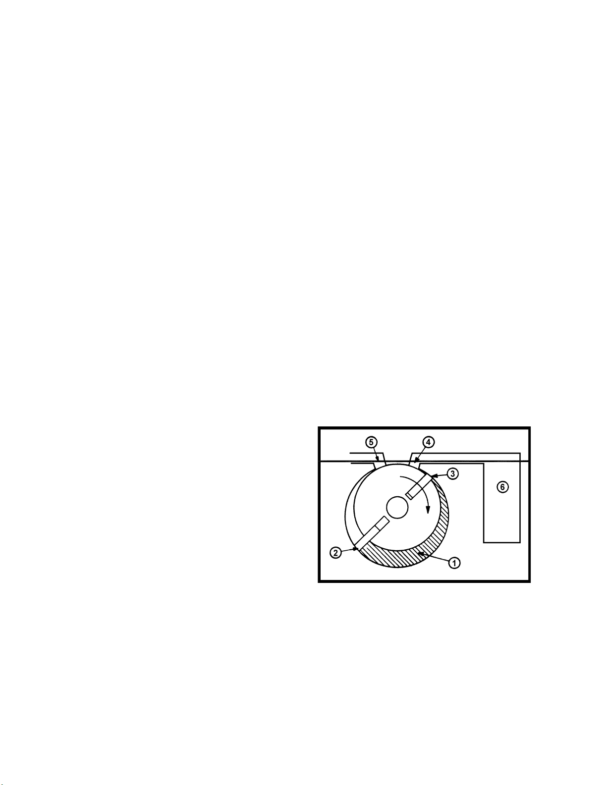
given space to be successfully enlarged and diminished. Figure 2.1 illustrates a section through a typical stage of
rotary-vane pump. Note that this figure is not intended to illustrate exactly the internal components of the pumps; its
purpose is to illustrate the general operating principles of vacuum pumps.
The rotary action of the pump creates a hollow space of chamber (1) which expands as the pump rotates. As the
chamber expands, the pressure in the chamber decreases. As a result, gas is drawn into the chamber due to the
difference in pressure between the chamber and the inlet (4) to the chamber. (The inlet is the only place where gas
can flow into the chamber.) Once the vane (3) moves past the inlet (4), it seals the inlet against the chamber (1) and
the gas becomes trapped between the vanes (2 and 3). The chamber (1) formed by the enclosed space between the
vanes then begins to decrease in volume as the rotor revolves, compressing the gas. The pressure of the compressed
gas becomes greater than atmospheric pressure. When the vane (2) moves past the exhaust port (5) the compressed
gas in the chamber is forced out through the exhaust port.
Figure 2.1
Typical Rotary Vane
Pump, Schematic Diagram
This expansion/compression cycle constitutes one complete cycle of the pump operation. This cycle is repeated as
the vane (2) passes the intake port and seals it against the atmosphere. Therefore, two pump cycles are performed during each revolution of the pump rotor.
8

2.03 Effects of Continued Pressure Reduction
The quantity of gas in the vessel (6) is reduced with each evacuation cycle. The gas remaining in the vessel expands
to fill the vessel and consequently with each cycle the pressure in the vessel is reduced. This is a manifestation of
Boyle’s Law which states that, for a constant temperature, the volume of a body of gas is inversely proportional to its
pressure; i.e., if the volume is enlarged the pressure must be reduced.
As the amount of gas in the vessel is steadily diminished, its pressure is correspondingly reduced. The action of the
pump must therefore compress a successively smaller quantity of gas with each cycle to something greater than
atmospheric pressure in order to expel it from the pump.
At the beginning of an evacuation sequence, the compression ratio is very small. In the first cycle of operation the
pump draws in a volume of gas at atmospheric pressure and expels it at approximately atmospheric pressure. In
contrast, near its ultimate pressure, a pump draws in gas at (for example) 30 millitorr and must compress it to more
than 760,000 millitorr (atmospheric pressure) in order to expel it from the pump. Since the exhaust valve is generally
spring loaded to provide a good seal, the pressure required to open it is somewhat greater than atmospheric pressure.
Therefore, at an ultimate pressure of 1.3 x 10⁻⁴ mbar 0.1 millitorr, (1 x 10⁻⁴ Torr) the compression ratio performed by
the pump is greater than 1,000,000 to 1.
2.04 Ultimate Pressure
As described previously, a quantity of gas is removed from the system with each cycle of the pump. Therefore, the
pressure of the gas remaining in the system is reduced with each pump cycle. Since the pump can remove only a
small portion of the gas with each pump cycle, it is obvious that this method of evacuation can never completely
remove all the gas in the vessel. In addition to this, all the components of the system contain minute sources of gas
leakage which are impossible to seal completely against atmospheric pressure. Outgassing of materials within the
system provide additional sources of gas.
As a result, after prolonged pumping, a state of equilibrium is reached in which the gas introduced from all the leakage
sources is balanced by the ability of the pump to remove gas from the system. This state of equilibrium is referred to
as the ultimate pressure or blankoff pressure of the pump and its system. No matter how much additional pumping
time is provided, no further reduction in system pressure will be accomplished once ultimate pressure is attained.
2.05 Pump Mechanism Description
The Vacuum Pumps incorporate two in-line rotary-vane stages with interconnecting ports. When in operation, the
intake stage is at lower pressure and the exhaust stage is at higher pressure relative to each other. Each stage
contains a rotor assembly consisting of a rotor with two vanes and a stator. The two rotors are combined on one
shaft, and the two stators are combined in a common housing. The pump shaft turns the rotors, causing the vanes in
each section to sweep the surface of their stators. The vanes are pressed against the stators by centrifugal force.
Each stage has an exhaust valve. Gas expelled from the first stage exhaust passes through an interstage port to the
intake of the second stage. The second stage compresses the gas further, then expels it from the second stage
exhaust valve to the atmosphere.
An adjustable gas ballast valve is located in the pump’s exhaust stage. The purpose of the gas ballast is to reduce or
eliminate vapor condensation in the pump. The function of the gas ballast valve is described later in this section.
The pump is mounted inside an oil case which is a reservoir for the oil that lubricates the pump. The electric motor
shaft drives the pump shaft via a coupling. There is a coupling body on the end of each shaft; a coupling spider
between the two coupling bodies transfers the power from the motor shaft to the pump shaft.
2.06 Intake Anti-Suckback Protection
When power to the pump is turned off, this valve closes automatically, maintaining vacuum in the system being
evacuated. When the pump is turned on, the plunger opens the valve to allow gas to flow into the pump intake.
Please Note: Pump model 8925 does not have the anti-suckback protection if the gas ballast is open.
The system vacuum will not be maintained.
9

2.07 Pump Lubrication
To ensure efficient operation and proper maintenance, and to minimize noise and oil vapors, it is important to use the
correct type and quantity of oil. Welch DIRECTORR® Premium or Gold Vacuum Pump Oil has been developed to
have the proper viscosity, low vapor pressure, and chemical stability needed to produce peak pumping efficiency. The
ultimate vacuum guarantee on Welch pumps applies only when this oil is used. Therefore, DIRECTORR® Premium
or Gold Oil is the only oil recommended for use with these pumps. Each pump is supplied with a bottle of oil sufficient
for filling. Additional oil is available. See Section 9 - Accessories.
2.08 Exhaust Filter
Any oil-sealed vacuum pump tends to discharge oil mist from its exhaust port when the pump operates under high-flow
conditions, such as when the pump’s intake is at or near atmospheric pressure. Typically, oil mist in the form of a white
puff of “smoke” can be seen from the exhaust port when no filter is used. Once the vacuum level and the corresponding air flow through the pump are reduced, very little, if any, oil mist will be emitted.
An optional exhaust filter is recommended for any vacuum pump installation where the pump operates at high intake
pressures for a prolonged period of time. Oil droplets entrained in the pump’s exhaust are removed by the exhaust
filter element. Use of an exhaust filter typically reduces or baffles pump noise as well. Exhaust filters are sometimes
referred to as Oil Mist Eliminators. See Section 9 - Accessories.
2.09 Gas Ballast Valve
The gas ballast valve can increase the pump’s water vapor tolerance. (The gas ballast valve is sometimes referred to
as a vented exhaust valve.) In many vacuum pump applications the gases being pumped from a system are a
combination of permanent gases and undesirable vapors such as water vapor. Under some conditions, the vapors
condense in the second stage of the pump and contaminate the oil. The gas ballast valve reduces oil contamination by
decreasing or eliminating vapor condensation. Vapor condensation usually takes place in the compression stroke of the
second stage of the vacuum pump when the compression ratio between the initial pressure and the end pressure is
high. Opening the gas ballast valve will admit air to the second stage of the vacuum pump thereby reducing the partial
pressure of any vapor in the gas mix (Dalton’s Law). Diluting the vapor with air increases the condensation pressure.
Depending on the amount of air added, condensation of the vapor is either entirely avoided or substantially reduced.
When the gas ballast valve is open, the pump has to work a little harder, resulting in a slight increase in operating
temperature. The increase in temperature is small, however, and is not harmful to the pump. Also, the pump is slightly
noisier, and the pump’s ultimate pressure is somewhat reduced. Therefore, the gas ballast valve should be kept closed
when it is not needed. Note that the gas ballast is not equally effective on all vapors, so it does not always eliminate
condensation completely.
2.10 UNIBARB
TM
Intake Fitting - Simplifies Small Hose Connections
The UNIBARBTM intake fitting allows the user to be able to use 2 sizes of ID hose to connect to this system.
However, the choice of hose size can have a very marked difference on pumping speed. It is the best to have the
largest connection I.D.(internal diameters) as possible. However, we recognize many lab appliances use hose
barbs accepting small I.D. hose.The conductance of a tube is proportional to the cube of its diameter and inversely
proportional to its length. Therefore, connecting line should be as large in diameter and short in length as practical.
Included is a free hose clamp to hold the hose in place.
10

11

3.01 Specification Chart
ledoM509802985298
tnemecalpsiDriAeerF
zH06@)nim/L(MFC
zH05@h/3m)nim/L(
zH06@)nim/L(MFC
zH05@h/3m)nim/L(
Section 3: PUMP SPECIFICATIONS
)25(8.1
5.1)34(
deepSgnipmuPlanimoN
)34(5.1
3.1)63(
rroT*erusserPetamitlUdeetnarauGrroT3-01x24-01x34-01x4
)812(7.7
8.01)281(
)012(4.7
5.01)571(
)023(3.11
0.61)662(
)382(0.01
2.41)632(
rroT,ecnareloTropaVretaW
rh/mg,yticapaCropaVretaW
ABdleveLdnuoS654555
zH06@mprdeepSpmuP/rotoM
zH05@mpr
esahPelgniSzH06/05egatloV
zH06@)V032(V511@tnerruC
zH05@V032@tnerruC
rewopesroHrotoM4/12/14/3
)sretil(strauq,yticapaCliO)4.0(24.0)2.1(3.1)1.1(2.1
noitcennoCekatnI
)mm(sehcnini.D.IdedeeNgnibuT
noitcennoCtsuahxEdaerhT02-"4/3daerhT02-"1daerhT02-"1
noitcennoCtsallaBsaGdaerhT23-01daerhT23-01daerhT23-01
)gk(.sbl,thgieW)1.11(5.42)6.62(5.85)3.13(96
6
03
0543
5782
)A9.1(A8.3
A2.1
"61/7&"61/3
,elbavomerbrabinU
02-4/3dedaerht
2-FENU
61/7ro61/3
)11ro5(
51
081
5271
5241
)A4.3(A8.6
A4.3
"61/31&"61/9
,elbavomerbrabinU
02-1dedaerht
2-FENU
61/31ro61/9
)02ro41(
51
081
5271
5241
)A0.5(A0.01
A0.5
"61/31&"61/9
,elbavomerbrabinU
02-1dedaerht
2-FENU
61/31ro61/9
)02ro41(
snoisnemiDllarevO
)mc(niL
)mc(niW
)mc(niH
)gk(.sbl,thgieWgnippihS)8.11(62)2.23(17)6.43(77
snoisnemiDnotraCgnippihS
)mc(niL
)mc(niW
)mc(niH
.oN.taC)lanoitpO(retliFtsuahxE
.oN.taCepyTliO
)8.63(5.41
)31(1.5
)3.12(4.8
)3.35(12
)5.61(5.6
)6.82(2.11
B6141
7141
P5998
G5998
)8.25(8.02
)9.71(1.7
)9.72(0.11
)7.37(92
)4.52(01
)6.53(41
01-P7141
C6141
P5998
G5998
* Partial measurement based upon the American Vacuum Society Test Procedure No. AVS 5.1-1963
using a trapped McLeod Gauge.
12
)4.65(2.22
)9.71(1.7
)9.72(0.11
)7.37(92
)4.52(01
)6.53(41
01-P7141
C6141
P5998
G5998

ledoM709821987198
tnemecalpsiDriAeerF
zH06@)nim/L(MFC
zH05@h/3m)nim/L(
deepSgnipmuPlanimoN
zH06@)nim/L(MFC
zH05@h/3m)nim/L(
rroT*erusserPetamitlUdeetnarauGrroT4-01x1rroT4-01x1rroT4-01x1
rroT,ecnareloTropaVretaW912121
ABdleveLdnuoS050505
)07(6.2
86.3)6.5(
)46(3.2
2.3)35(
)801(8.3
73.5)68(
)69(4.3
87.4)08(
)371(1.6
36.8)831(
)051(3.5
15.7)521(
zH06@mprdeepSpmuP/rotoM
zH05@mpr
esahPelgniSzH06/05egatloV
zH06@)V032(V511@tnerruC
zH05@V032@tnerruC
rewopesroHrotoM2/12/12/1
)sretil(strauq,yticapaCliO)59.0(0.1)68.0(9.0)67.0(8.0
noitcennoCekatnI
)mm(sehcnini.D.IdedeeNgnibuT
noitcennoCtsuahxEdaerhT02-"1daerhT02-"1daerhT02-"1
noitcennoCtsallaBsaGdaerhT23-01daerhT23-01daerhT23-01
)gk(.sbl,thgieW)81(04)81(14)22(84
snoisnemiDllarevO
)mc(niL
)mc(niW
)mc(niH
5271
5241
)A3.2(A6.4
A1.2
"61/31&"61/7
brabinU
,elbavomer
02-1dedaerht
2-FENU
61/31ro61/7
)02ro11(
)7.74(8.81
)6.61(5.6
)4.42(6.9
5271
5241
)A3.2(A6.4
A1.2
"61/31&"61/7
brabinU
,elbavomer
02-1dedaerht
2-FENU
61/31ro61/7
)02ro11(
)7.74(8.81
)6.61(5.6
)4.42(6.9
5271
5241
)A3.2(A6.4
A1.2
"61/31&"61/7
brabinU
,elbavomer
02-1dedaerht
2-FENU
61/31ro61/7
)02ro11(
)7.74(8.81
)6.61(5.6
)4.42(6.9
)gk(.sbl,thgieWgnippihS)12(64)12(64)42(35
snoisnemiDnotraCgnippihS
)mc(niL
)mc(niW
)mc(niH
.oN.taC)lanoitpO(retliFtsuahxE
.oN.taCepyTliO
)5.37(9.82
)5.72(8.01
)0.53(7.31
P7141
C6141
P5998
G5998
)5.37(9.82
)5.72(8.01
)0.53(7.31
P7141
C6141
P5998
G5998
* Partial measurement based upon the American Vacuum Society Test Procedure No. AVS 5.1-1963
using a trapped McLeod Gauge.
)5.37(9.82
)5.72(8.01
)0.53(7.31
7-P7141
C6141
P5998
G5998
13

Section 4: MOTOR POWER SPECIFICATIONS / FEATURES
4.01 Motor Specification Chart
.oN.taCegatloV.qerFesahP.P.HrofderiWyrotcaFerutaeFlaicepSlavorppA
A5098 032/5110614/1zH06,V511ledoMdradnatSASC
10-C5098 032/5110614/1zH06,V511gulPdroCeniLSUV032htiWASC
20-C5098 0320514/1zH05,V032gulPdroC"okuhcS"naeporuEhtiWEC
01-C5098 032/5110614/1V032gulPdroC"okuhcS"naeporuEhtiWASC
A7098 032/5110612/1zH06,V511ledoMdradnatSASC
20-C7098 0320512/1zH05,V032gulPdroC"okuhcS"naeporuEhtiWEC
50-C7098 00106/0512/1V001gulPdroCeniLSUhtiwnapaJroF
A2198 032/5110612/1zH06,V511ledoMdradnatSASC
20-C2198 0320512/1zH05,V032gulPdroC"okuhcS"naeporuEhtiWEC
50-C2198 00106/0512/1zH06/05,V001gulPdroCeniLSUhtiwnapaJroF
A7198 032/5110612/1zH06,V511ledoMdradnatSASC
20-C7198 0320512/1zH05,V032gulPdroC"okuhcS"naeporuEhtiWEC
50-C7198 00106/0512/1zH06/05,V001gulPdroCeniLSUhtiwnapaJroF
W7198 5110612/1zH06,V511naicirtceledeifilauqybderiweboT-
A0298 032-802/51106/0514/3zH06,V511ledoMdradnatSASC
10-C0298 032-802/51106/0514/3zH06,V032gulPdroCeniLSUV032htiWASC
20-C0298 032-802/51106/0514/3zH05,V032gulPdroC"okuhcS"naeporuEhtiWEC
A5298 032-802/51106/0514/3zH06,V511ledoMdradnatSASC
10-C5298 032-802/51106/0514/3zH06,V032gulPdroCeniLSUV032htiWASC
20-C5298 032-802/51106/0514/3zH05,V032gulPdroC"okuhcS"naeporuEhtiWEC
W5298 5110612/1zH06,V511naicirtceledeifilauqybderiweboT-
14
 Loading...