

Page 1
Page 2

Chelsio T5 Unified Wire for Windows ii
This document and related products are distributed under licenses restricting their use, copying, distribution,
and reverse-engineering.
No part of this document may be reproduced in any form or by any means without prior written permission
by Chelsio Communications.
All third party trademarks are copyright of their respective owners.
THIS DOCUMENTATION IS PROVIDED “AS IS” AND WITHOUT ANY EXPRESS OR IMPLIED
WARRANTIES, INCLUDING, WITHOUT LIMITATION, THE IMPLIED WARRANTIES OF
MERCHANTABILITY AND FITNESS FOR A PARTICULAR PURPOSE.
THE USE OF THE SOFTWARE AND ANY ASSOCIATED MATERIALS (COLLECTIVELY THE
“SOFTWARE”) IS SUBJECT TO THE SOFTWARE LICENSE TERMS OF CHELSIO COMMUNICATIONS,
INC.
Sales
For all sales inquiries please send email to sales@chelsio.com
Support
For all support related questions please send email to support@chelsio.com
Copyright © 2016. Chelsio Communications. All Rights Reserved.
Chelsio ® is a registered trademark of Chelsio Communications.
All other marks and names mentioned herein may be trademarks of their respective companies.
Chelsio Communications (Headquarters)
209 North Fair Oaks Avenue,
Sunnyvale, CA 94085
U.S.A
www.chelsio.com
Tel: 408.962.3600
Fax: 408.962.3661
Chelsio (India) Private Limited
Subramanya Arcade, Floor 3, Tower B
No. 12, Bannerghatta Road,
Bangalore-560029
Karnataka,
India
Tel: +1-91-80-4039-6800
Chelsio KK (Japan)
Yamato Building 8F,
5-27-3 Sendagaya,
Shibuya-ku,
Tokyo 151-0051,
Japan
Page 3

Chelsio T5 Unified Wire for Windows iii
Document History
Version
Revision Date
1.3.6
11/19/2015
1.3.7
12/11/2015
1.3.8
01/28/2016
1.3.9
03/04/2016
1.4.0
04/21/2016
1.4.1
05/13/2016
1.4.2
06/27/2016
1.4.3
07/25/2016
1.4.4
07/29/2016
1.4.5
08/16/2016
1.4.6
08/26/2016
1.4.7
10/14/2016
Page 4

Chelsio T5 Unified Wire for Windows iv
TABLE OF CONTENTS
I. CHELSIO UNIFIED WIRE 7
1. Introduction 8
1.1. Features 8
1.2. Hardware Requirements 9
1.3. Software Requirements 9
1.4. Package Contents 9
2. Hardware Installation 10
3. Software/Driver Installation 11
3.1. Prerequisites 11
3.2. Unified Wire Installer 12
3.3. Nano Server Installer 21
3.4. Zip Package 22
4. Configuring Chelsio Network Interfaces 26
4.1. Configuring 40G Adapters 26
4.2. Assigning IP address 29
5. Mass Deployment (Installer) 31
5.1. Pre-deployment Configuration 31
5.2. Flashing Option ROM 33
5.3. Erasing Option ROM 41
5.4. Configuring using UM CLI 42
6. cxgbtool/cxgbnano help 48
7. Firmware Update 93
8. Software/Driver Uninstallation 94
8.1. Installer 94
8.2. Zip Package 96
9. Software/Driver Update 97
II. NDIS FUNCTION 98
1. Introduction 99
1.1. Hardware Requirements 99
1.2. Software Requirements 99
2. Software/Driver Configuration and Fine-tuning 100
2.1. Advanced Configuration 100
2.2. NVGRE Offload 107
2.3. VXLAN Task Offload 107
2.4. Virtual RSS (vRSS) 107
III. IWARP (ND) 109
1. Introduction 110
1.1. Hardware Requirements 110
Page 5

Chelsio T5 Unified Wire for Windows v
1.2. Software Requirements 110
2. Software/Driver Configuration and Fine-tuning 111
2.1. Registering iWARP(ND) driver 111
IV. SMB DIRECT 112
3. Introduction 113
3.1. Hardware Requirements 113
3.2. Software Requirements 113
4. Software/Driver Configuration and Fine-tuning 114
4.1. Enabling SMB Direct 114
4.2. Verifying RDMA 114
4.3. RDMA/NVGRE concurrent (Mode 2) 115
4.4. Troubleshooting 116
V. NDIS SR-IOV 117
1. Introduction 118
1.1. Hardware Requirements 118
1.2. Software Requirements 118
2. Software/Driver Configuration and Fine-tuning 119
2.1. Enabling SR-IOV 119
2.2. vSwitch Configuration 122
2.3. Guest (VM) Configuration 122
VI. DATA CENTER BRIDGING (DCB) 123
1. Introduction 124
1.1. Hardware Requirements 124
1.2. Software Requirements 124
2. Software/Driver Configuration and Fine-tuning 125
2.1. Installing DCB 125
2.2. Quality of Service (QoS) 125
2.3. Configuring Dell Force10 Switch 126
VII. UNIFIED WIRE MANAGER (UM) 129
1. Introduction 130
1.1. Features 130
1.2. Reference Architecture 131
1.3. Unified Wire Manager Components 131
1.4. Authentication and encryption 132
2. Hardware and Software 133
2.1. Supported Adapters 133
2.2. Platform/Component Matrix 133
2.3. Platform/Driver Matrix 133
Page 6

Chelsio T5 Unified Wire for Windows vi
3. Installation (Zip Package) 134
4. Configuration 139
4.1. Configuring Management Station 139
5. Verifying UM components status 141
5.1. Verifying Management Agent 141
5.2. Verifying Management Client 142
5.3. Verifying Management Station 142
6. Management Agent 143
6.1. Communication 143
6.2. Service configuration 143
6.3. Firewall 143
7. CLI client 144
7.1. CLI Help system 144
7.2. Client conflict resolution 144
8. Web GUI client 145
8.1. Management Station 145
8.2. Accessing Web Management Interface 146
8.3. Layout and Navigation 148
8.4. Home page 149
8.5. System page 159
8.6. Network page 163
8.7. Storage 178
8.8. Hardware Features 202
9. Uninstallation 214
VIII. UM FOR WIN PE 218
1. Introduction 219
1.1. Hardware Requirements 219
1.2. Software Requirements 220
1.3. Examples 220
IX. APPENDIX 224
Chelsio End-User License Agreement (EULA) 225
Page 7

Chapter I. Chelsio Unified Wire
Chelsio T5 Unified Wire for Windows 7
I. Chelsio Unified Wire
Page 8

Chapter I. Chelsio Unified Wire
Chelsio T5 Unified Wire for Windows 8
1. Introduction
Thank you for choosing Chelsio T5 Unified Wire adapters. These high speed, single chip,
single firmware cards provide enterprises and data centers with high performance solutions for
various Network and Storage related requirements.
The Terminator 5 (T5) is Chelsio’s next generation of highly integrated, hyper-virtualized
40/10GbE controllers. The T5 is built around a programmable protocol-processing engine, with
full offload of a complete Unified Wire solution comprising NIC, TOE, iWARP RDMA, iSCSI, FCoE
and NAT support. It scales true 40Gb line rate operation from a single TCP connection to
thousands of connections, and allows simultaneous low latency and high bandwidth operation
thanks to multiple physical channels through the ASIC.
Ideal for all data, storage and high performance clustering applications, the T5 adapters
enable a unified fabric over a single wire by simultaneously running all unmodified IP sockets,
Fibre Channel and InfiniBand applications over Ethernet at line rate.
Designed for deployment in virtualized data centers, cloud service installations and high
performance computing environments, Chelsio T5 adapters bring a new level of performance
metrics and functional capabilities to the computer networking industry.
1.1. Features
Chelsio Unified Wire for Windows is an easy to use utility developed to provide installation of 64bit Windows based drivers and tools for Chelsio's T5 Unified Wire adapters.
It consists of the following components:
NDIS Function driver (NIC)
NVGRE Offload
VXLAN Task Offload
SMB Direct
RDMA/NVGRE concurrent (Mode 2)
iWARP (ND)
NDIS SR-IOV
Virtual RSS (vRSS)
Data Center Bridging (DCB)
Unified Wire Manager (UM)
UM for Win PE
Page 9

Chapter I. Chelsio Unified Wire
Chelsio T5 Unified Wire for Windows 9
1.2. Hardware Requirements
The Chelsio T5 Unified Wire supports all x64 architectures supporting PCIE (x4, x8) slots.
AMD CPUs, 64-bit (x86_64/amd64)
Intel CPUs, 64-bit (x86_64)
1.3. Software Requirements
The Chelsio T5 Unified Wire software has been developed to run on Windows based platforms.
To know more about the complete list of versions supported by each driver/software, please refer
their respective sections.
1.4. Package Contents
Unified Wire Installer
Chelsio T5 Unified Wire comes with an interactive installer and support documentation. The
documentation, consisting of README, Release Notes and User’s Guide (this document), can
be found in the <system_drive>\ChelsioUwire\docs\ directory after installing Chelsio Unified Wire.
Zip Package
The zip package contains driver files, UM installer, UM for Win PE application, firmware binaries,
adapter configuration binaries and support documentation (docs folder).
Nano Server Installer
The Nano Server Installer package contains driver files, firmware binaries, adapter configuration
binaries and support documentation (docs folder)
The Chelsio Unified Wire supports 3.3v PCI bus only. Running an adapter on a
PCI x4 slot is not recommended as performance will be significantly reduced by
the limitations of PCI.
Note
T4 family of adapters are not supported on Windows 2016 Server & 10 AU Client
versions.
Note
Drivers are WHQL certified.
Note
Page 10

Chapter I. Chelsio Unified Wire
Chelsio T5 Unified Wire for Windows 10
2. Hardware Installation
i. Shutdown/power off your system.
ii. Power off all remaining peripherals attached to your system.
iii. Unpack the Chelsio adapter and place it on an anti-static surface.
iv. Remove the system case cover according to the system manufacturer’s instructions.
v. Remove the PCI filler plate from the slot where you will install the Ethernet adapter.
vi. For maximum performance, it is highly recommended to install the adapter into a PCIE x8
slot.
vii. Holding the Chelsio adapter by the edges, align the edge connector with the PCI connector
on the motherboard. Apply even pressure on both edges until the card is firmly seated. It may
be necessary to remove the SFP (transceiver) modules prior to inserting the adapter.
viii. Secure the Chelsio adapter with a screw, or other securing mechanism, as described by the
system manufacturer’s instructions. Replace the case cover.
ix. After securing the card, ensure that the card is still fully seated in the PCIE x8 slot as
sometimes the process of securing the card causes the card to become unseated.
x. Connect a fiber cable, multi-mode for short range (SR) optics or single-mode for long range
(LR) optics, to the 10Gb Ethernet adapter or regular Ethernet cable for the 1Gb Ethernet
adapter.
xi. Power on your system.
xii. Verify if the adapter was installed successfully. To do so, open Device Manager in Control
Panel.
xiii. Under Other devices section, Chelsio adapter should be listed as Ethernet Controller. If the
adapter is not listed, right-click on the system name or click on the Actions menu and select
Scan for hardware changes
For Chelsio adapters, the physical functions are currently assigned as:
Physical functions 0 - 3: for the SR-IOV functions
Physical function 4: for all NIC functions of the card
Physical function 5: for iSCSI
Physical function 6: for FCoE
Physical function 7: Currently not assigned
xiv. Once the Unified Wire package is installed, open Device Manager again. Expand Network
adapters section and now Chelsio adapter should be listed.
Network device names for Chelsio’s physical ports are assigned using the
following convention: the port farthest from the motherboard will appear as the
first Ethernet interface. However, for T5 40G adapters, the association of physical
Ethernet ports and their corresponding network device names is opposite. For
these adapters, the port nearest to the motherboard will appear as the first
network interface.
Note
Page 11

Chapter I. Chelsio Unified Wire
Chelsio T5 Unified Wire for Windows 11
3. Software/Driver Installation
Chelsio Unified Wire can be installed using the Installer or the zip package. Refer the relevant
section below depending on the method of installation selected.
3.1. Prerequisites
Please ensure that the following requirements are met, before proceeding with the installation:
Unified Wire Installer
Download and install the latest Microsoft Visual C++ Redistributable Packages for Visual Studio
(x86 and x64).
NDIS SR-IOV
Enable SR-IOV in the machine.
Unified Wire Manager (Installer & Zip Package)
The Unified Wire installer has been designed to install Unified Wire Manager (UM) along with
driver components by default, hence no separate installation is required. In case of zip package,
you will have to manually run the UM installer located in ChelsioUwire-x.x.x.xx/UM folder (See
Unified Wire Manager chapter for for more information). Based on the Windows version running
on the system, the three UM components, i.e. Management Agent, Client and Station will be
installed. If an older version of UM exists, the installer will upgrade it to the version provided in
the package.
Management Agent
If you wish to install Management Agent, please make sure that Microsoft .Net Framework 3.5
is installed before proceeding with the installation.
Management Station
If you wish to install Management Station, please make sure that the following requirements are
met before proceeding with the installation:
i. Install Python 2.6.6 (32-bit). (Download from here)
ii. Ensure that the path to python binary (typically C:\Python26), is added to PATH system
variable.
iii. Install Apache HTTP Server 2.2 with SSL. (Download from here)
iv. If the Apache Server is running, it should be stopped before starting the installation process.
Page 12
Chapter I. Chelsio Unified Wire
Chelsio T5 Unified Wire for Windows 12
3.2. Unified Wire Installer
Chelsio Unified Wire Installer provides two methods of installation: GUI or CLI mode. GUI mode
provides an interactive GUI installer with customizable options. Whereas, CLI mode enables
unattended installation of Chelsio drivers and software thereby relieving the user from monitoring
the installation process and providing input via dialog boxes.
Enabling Test Signing
In case the drivers in the package are not WHQL certified, follow the steps mentioned below to
enable test signing on your system:
i. Goto Start->Run command option, enter "cmd" and press OK. This will open the command
prompt utility.
ii. Run the following command:
C:\Users\Administrator> bcdedit /set testsigning on
iii. Reboot the machine for the changes to take effect.
GUI mode (Installer)
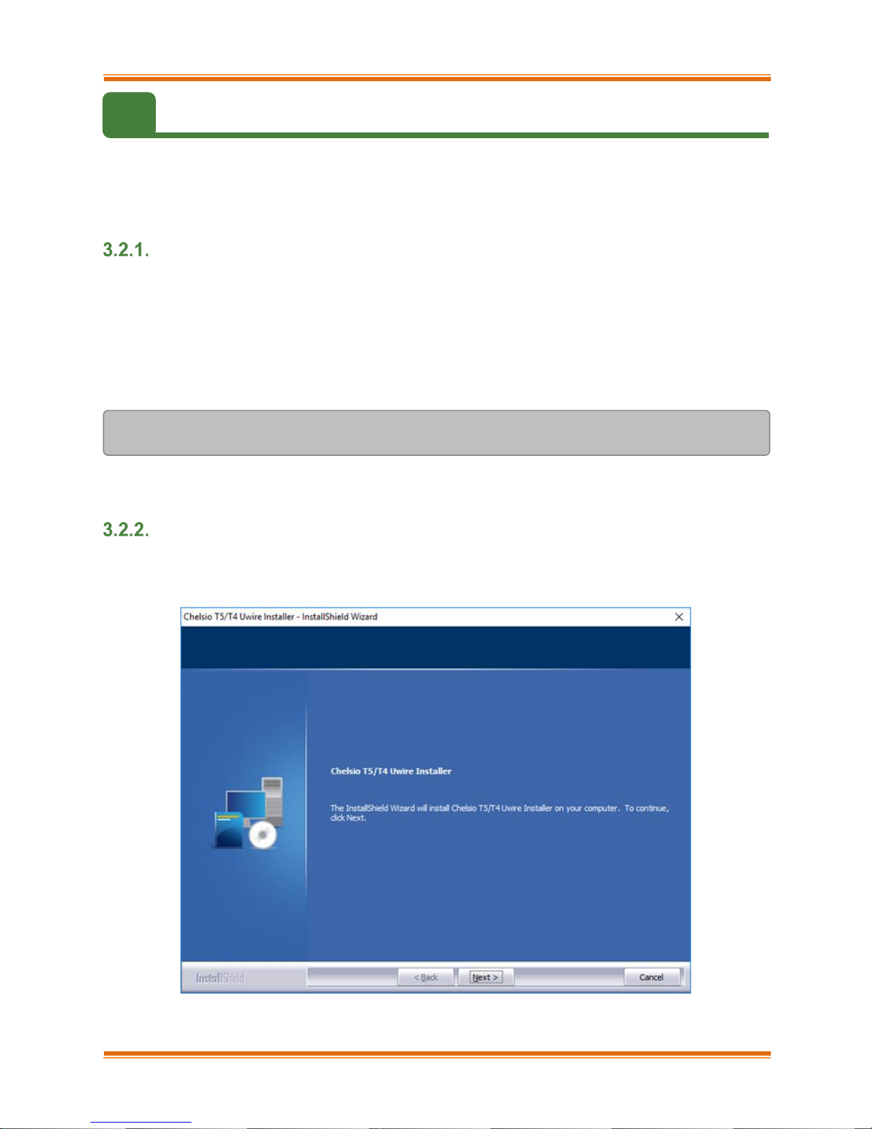
i. Run the ChelsioUwire-x.x.x.xx.exe installer application.
ii. Click Next for the Chelsio End User License Agreement Window.
Figure 1 - Unified Wire installer welcome window
Page 13
Chapter I. Chelsio Unified Wire
Chelsio T5 Unified Wire for Windows 13
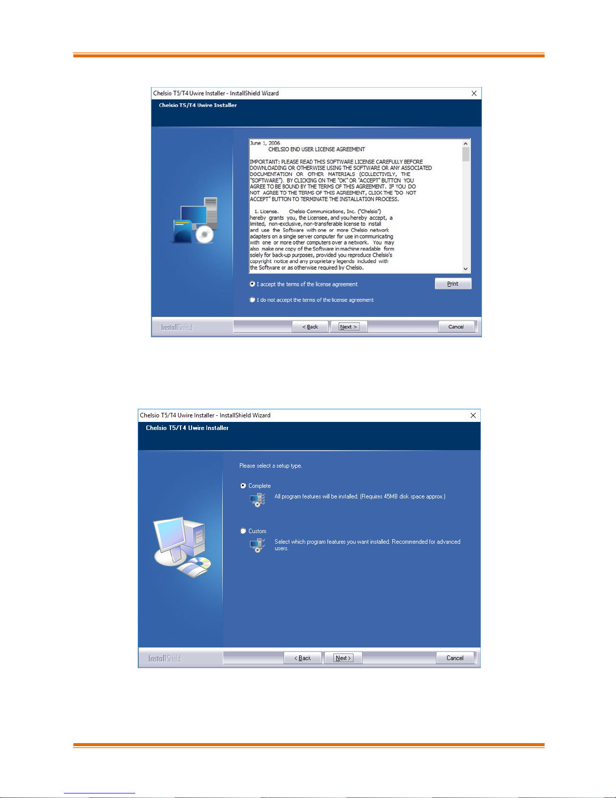
iii. Select the radio button I accept the terms of the license agreement and click Next.
Figure 2 - Chelsio EULA window
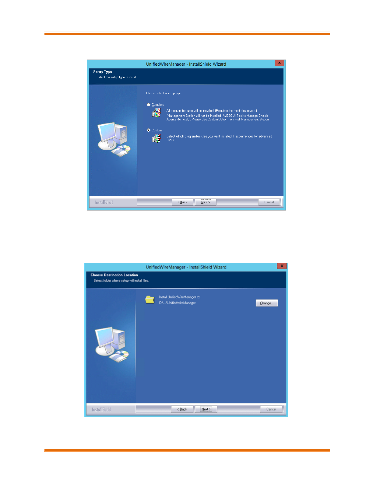
iv. Now, either select Complete for complete package installation or else select Custom radio
button to customize the installation.
Figure 3 - Select setup (installation) type
Page 14
Chapter I. Chelsio Unified Wire
Chelsio T5 Unified Wire for Windows 14
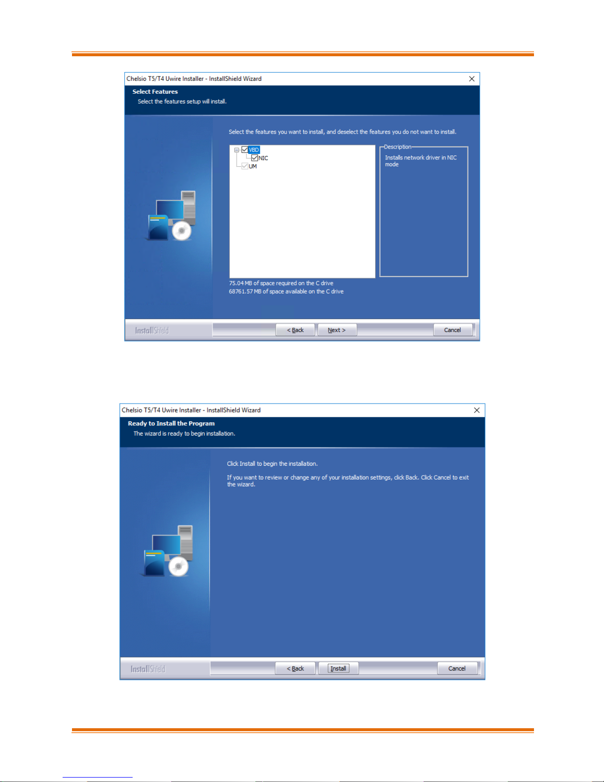
Figure 4 - Customizing the installation
v. Click Install to start the installation.
Figure 5 - Start installation
Page 15
Chapter I. Chelsio Unified Wire
Chelsio T5 Unified Wire for Windows 15
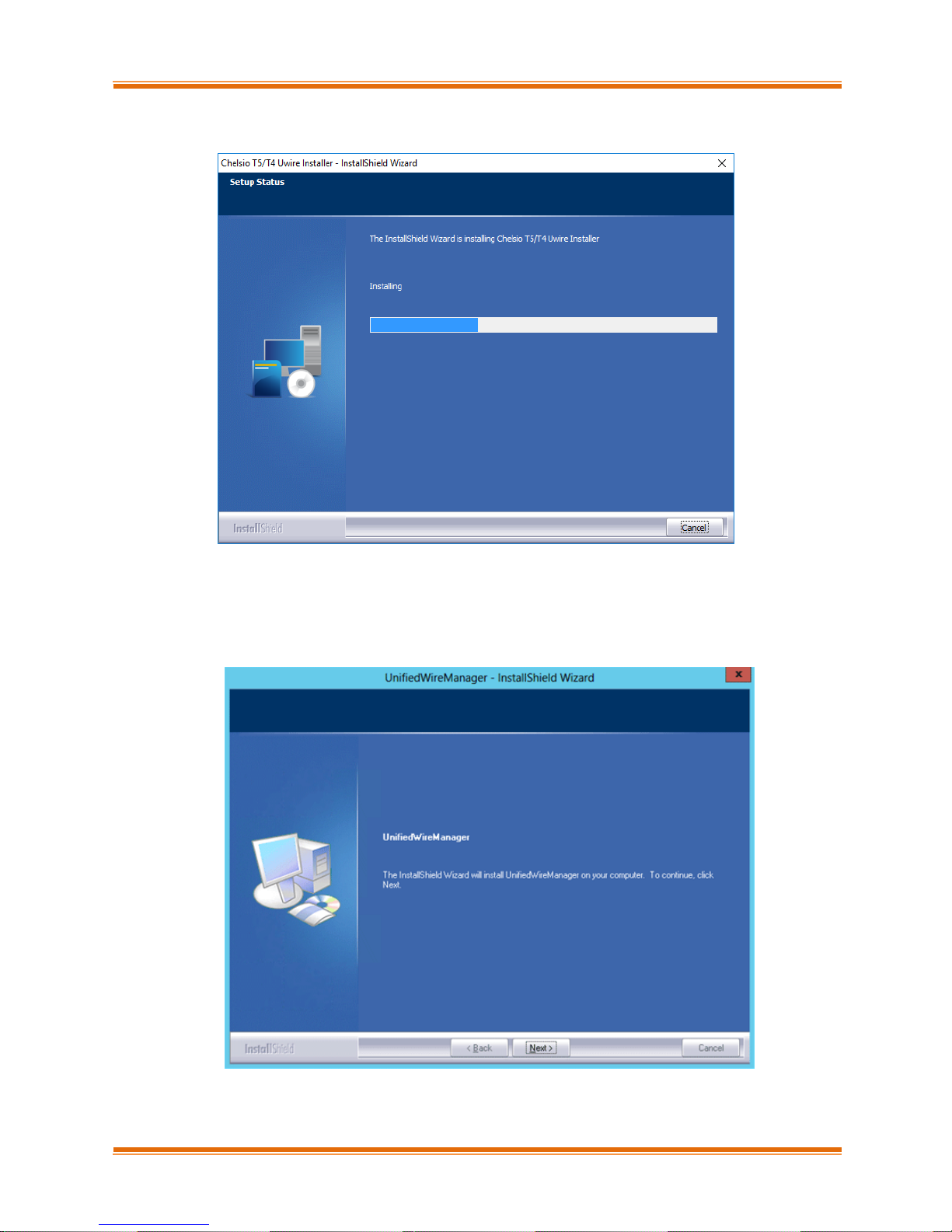
vi. Selected driver components will now be installed.
Figure 6 - Installation in progress
vii. After successful installation of driver(s), the Unified Wire Manager installer will be invoked.
Click Next for the Chelsio End User License Agreement Window.
Figure 7 - UM installer welcome window
Page 16
Chapter I. Chelsio Unified Wire
Chelsio T5 Unified Wire for Windows 16
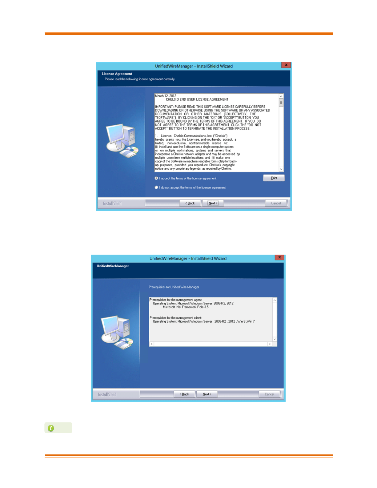
viii. Select the radio button I accept the terms of the license agreement and click Next.
Figure 8 - Chelsio EULA window
ix. The next window will display the prerequisites for various UM components. Ensure that they
are met before proceeding. Click Next.
Figure 9 - UM prerequisites window
If prerequisites mentioned are not met, installation of UM will fail. Driver installation
will however continue.
Note
Page 17
Chapter I. Chelsio Unified Wire
Chelsio T5 Unified Wire for Windows 17
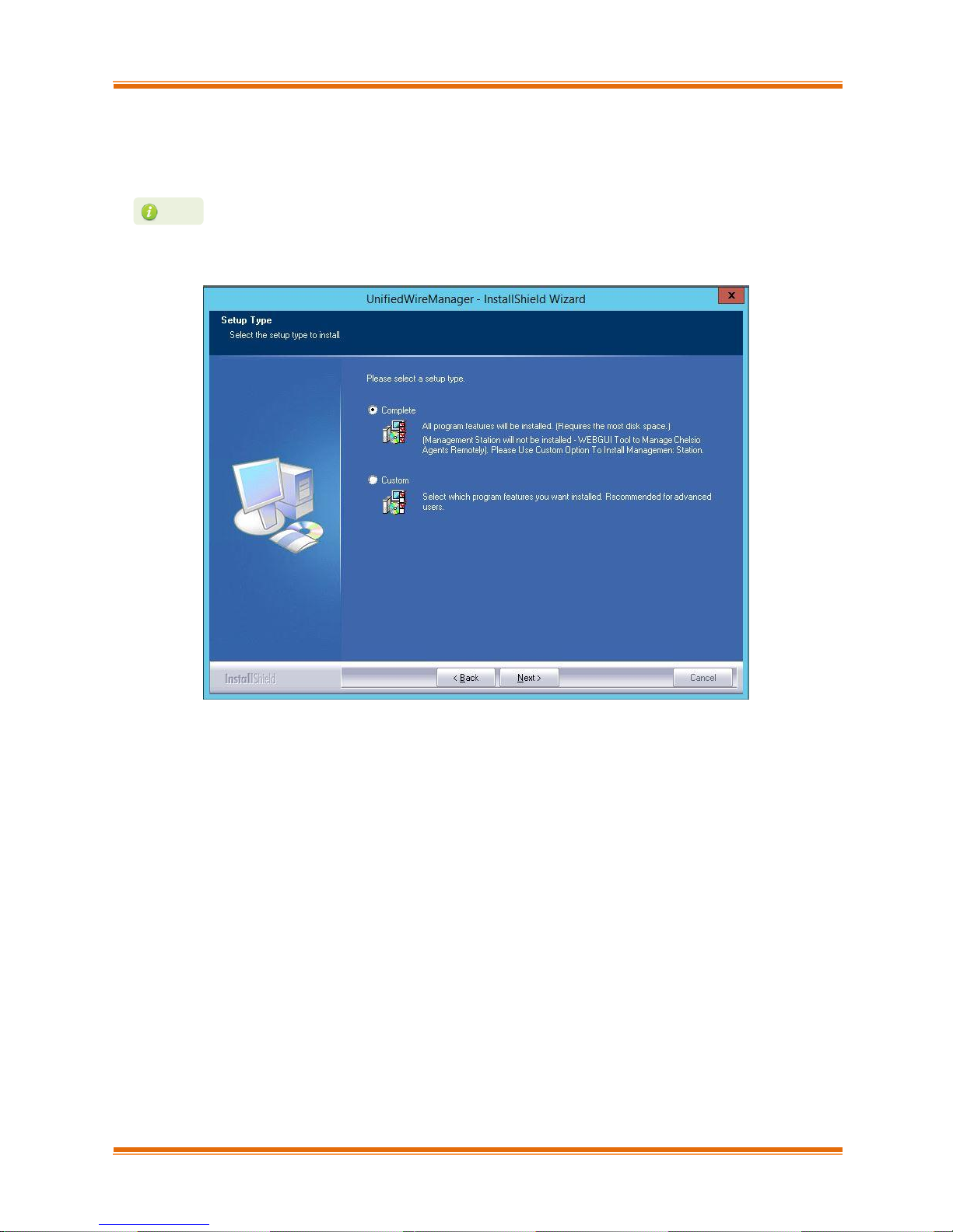
x. Now, either select Complete for complete package installation or else select Custom radio
button to customize the installation. The Custom option provides the option to change the
installation path and which UM components to install. Click Next.
Figure 10 - Select setup (installation) type
If Management Station is selected, please make sure that all related prerequisites
are met before proceeding (See Prerequisites) or else the component will be skipped
during installation.
Note
Page 18
Chapter I. Chelsio Unified Wire
Chelsio T5 Unified Wire for Windows 18
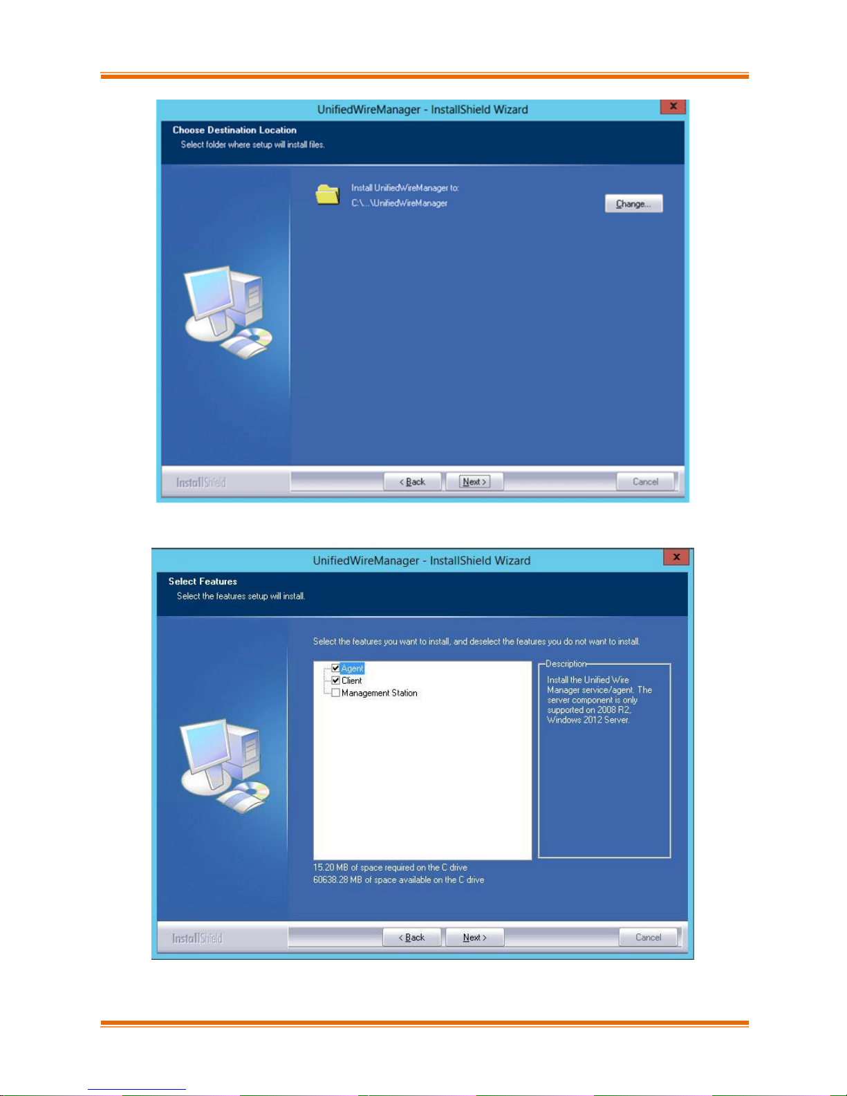
Figure 11 - Changing UM installation path
Figure 12 - Selecting UM components to install
Page 19
Chapter I. Chelsio Unified Wire
Chelsio T5 Unified Wire for Windows 19
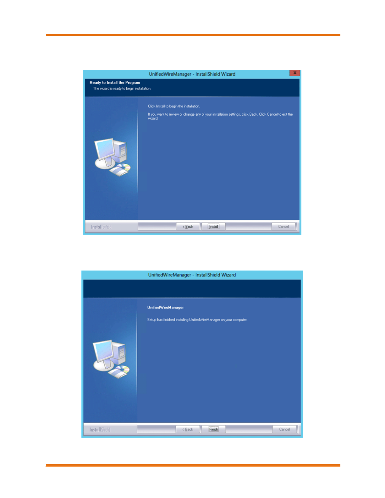
xi. Click Install to start the installation. Unified Wire Manager will now be installed with the
selected options.
Figure 13 - Starting UM installation
xii. Click Finish to exit from the UM Installer.
Figure 14 - Finishing UM installation
Page 20
Chapter I. Chelsio Unified Wire
Chelsio T5 Unified Wire for Windows 20
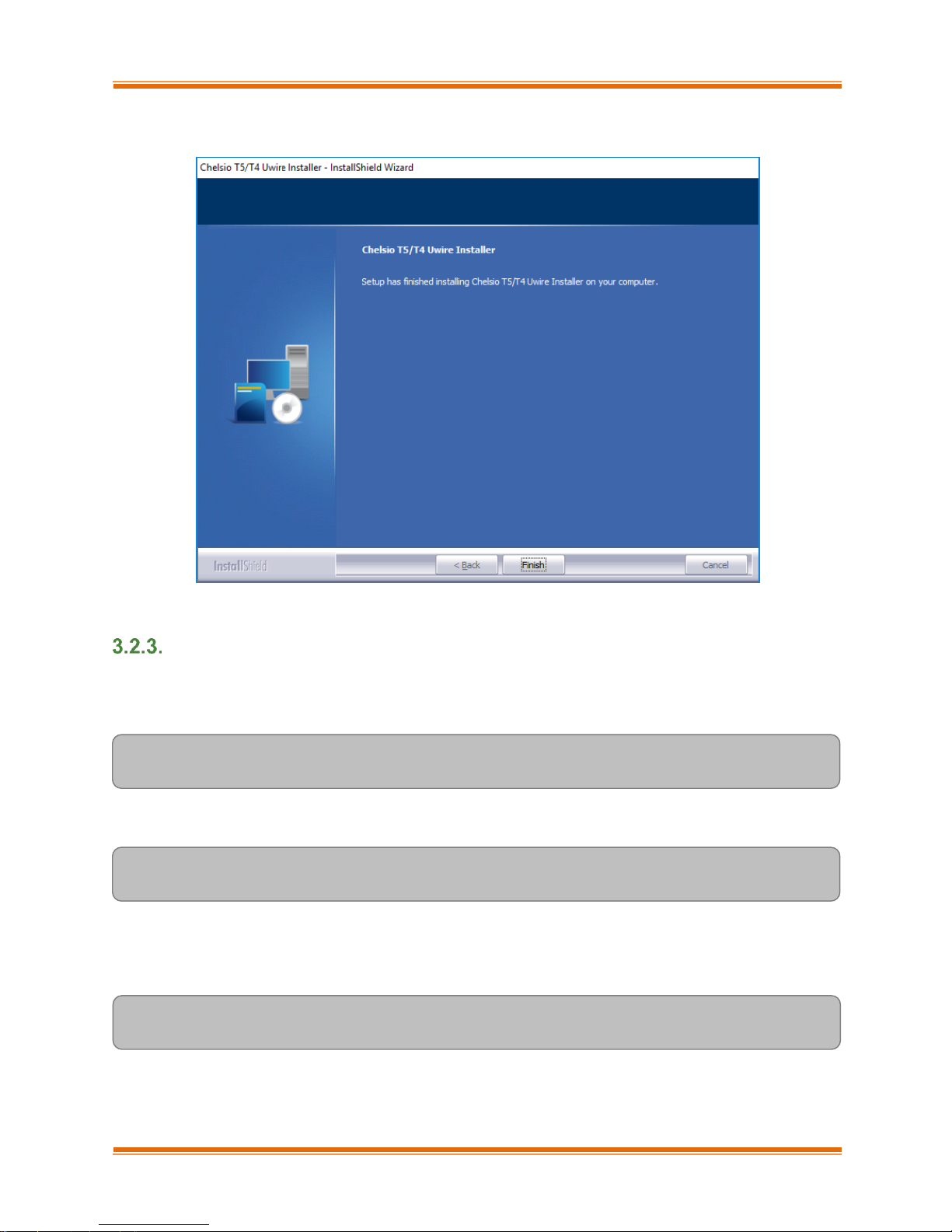
xiii. Click Finish to exit from the Unified Wire Installer.
Figure 15 - Finishing Unified Wire installation
CLI mode (Silent Installation)
To install drivers/software using this feature, open command prompt and execute the following
command:
C:\Users\Administrator>ChelsioUwire-x.x.x.xx.exe –in <driver(s)>
E.g.:
C:\Users\Administrator>ChelsioUwire-x.x.x.xx.exe –in all
The above command will install all the drivers and UM Agent.
To add a driver to an existing list of already installed drivers, use the following command:
C:\Users\Administrator>ChelsioUwire-x.x.x.x.exe –add <driver(s)>
Page 21

Chapter I. Chelsio Unified Wire
Chelsio T5 Unified Wire for Windows 21
To know more about other parameters and options, execute the following command:
C:\Users\Administrator>ChelsioUwire-x.x.x.xx.exe -help
The above command will create a help file, ChelsioUwire-x.x.x.xx_help.txt, in the present working
directory which contains the complete list of command line syntax required for performing all the
necessary CLI operations.
3.3. Nano Server Installer
Follow the steps mentioned below to install Unified Wire on a Nano Server machine:
i. Download and unzip the driver package Chelsio-NANO-installer-x.x.x.xx.zip
ii. Connect to Nano Server machine and copy the package contents.
iii. Open PowerShell with administrative privileges and change your working directory to Chelsio-
NANO-installer-x.x.x.xx
iv. Run the installer
[nanomachine-ip]: PS D:\Chelsio-NANO-installer-x.x.x.xx> .\install.ps1 -in
all
A log file, Chelsio-installer.log, containing installation summary will be created in the same folder.
To know more about Installer parameters and options, view the help:
[nanomachine-ip]: PS D:\Chelsio-NANO-installer-x.x.x.xx> .\install.ps1 -h
A log file, ChelsioUwire-x.x.x.xx.log, is created in the same directory which keeps a
record of all the commands executed and their results.
Note
In case of non-WHQLed drivers, if Nano Server is freshly installed, the installer will
enable Test Signing. Reboot the machine and run the installer again.
Note
Page 22

Chapter I. Chelsio Unified Wire
Chelsio T5 Unified Wire for Windows 22
3.4. Zip Package
Chelsio Unified Wire zip package provides two methods of installation: Manual and using Offline
Windows Image. In Manual method, the driver components will have to be individually installed
using the Device Manager. Using the second method, you can add Chelsio driver components to
an offline OS image. The image can then be used to install Windows on your system.
Enabling Test Signing
In case the drivers in the package are not WHQL certified, please follow the steps mentioned
below to enable test signing before installing Unified Wire:
1. Open command prompt and run the following command to enable test signing:
C:\Users\Administrator>bcdedit /set testsigning on
2. Change your working directory to ChelsioUwire-x.x.x.xx/Selfsign/ and run the following
commands:
C:\ChelsioUwire-x.x.x.xx\Selfsign> .\certmgr.exe -add chelsiocert.cer -s -r
localmachine root
C:\ChelsioUwire-x.x.x.xx\Selfsign> .\certmgr.exe -add chelsiocert.cer -s -r
localmachine trustedpublisher
3. Reboot the machine for the changes to take effect.
Manual
Virtual Bus Driver
i. Open Device Manager (Control Panel -> System & Security-> System -> Device Manager),
click on System Devices, right click on Chelsio T5 40G/10G Enumerator and select
Update Driver Software.
ii. Select Browse my computer for driver software.
iii. Select Let me pick from a list of device drivers on my computer and click Next.
iv. Click on Have Disk Button and on the next screen browse for chvbdx64.inf file and click
Open and then OK.
Important
The driver components need to be installed strictly in the order described
here. Using any other order is not supported.
Before proceeding, open Device Manager and disable NDIS Miniport driver
(Network adapters->Chelsio Network Adapter) followed by Virtual Bus Driver
(System devices->Chelsio T5 40G/10G Bus Enumerator).
Page 23

Chapter I. Chelsio Unified Wire
Chelsio T5 Unified Wire for Windows 23
v. Click Next and driver installation will progress. Click Finish once the installation is complete.
NDIS Miniport driver
i. Open Device Manager (Control Panel -> System & Security-> System -> Device Manager),
click on Network Adapters, right click on the Chelsio network adapter and select Update
Driver Software.
ii. Select Browse my computer for driver software.
iii. Select Let me pick from a list of device drivers on my computer.
iv. Click on Have Disk Button and on the next screen browse for chnetx64.inf file and click
Open and then OK. Click Next and driver installation will progress. Click Finish once the
installation is complete.
Repeat the above steps for the other adapters.
Generic Function
i. Open Device Manager (Control Panel -> System & Security-> System -> Device Manager),
click on Network Adapters, right click on Chelsio T5 40G/10G Generic Function and
select Update Driver Software.
ii. Select Browse my computer for driver software.
iii. Select Let me pick from a list of device drivers on my computer.
iv. Click on Have Disk Button and on the next screen browse for chnullx64.inf file and click
Open and then OK.
v. Click Next and driver installation will progress. Click Finish once the installation is complete.
Offline Windows Image
You can use Windows Deployment Image Servicing and Management (DISM) tool to add Chelsio
driver components (.inf files) to an offline Windows image. For more information, visit the following
links:
http://technet.microsoft.com/en-us/library/hh825070.aspx
http://blogs.technet.com/b/heyscriptingguy/archive/2012/09/27/use-the-powershell-dism-
cmdlets-to-manage-windows-8.aspx
Nano Server: Driver Installation
Before installing Nano Server, the Chelsio driver components need to be added to the boot image
file. The following steps explain step-by-step procedure to add Chelsio VBD, NDIS and Null
drivers to the image file:
i. Copy NanoServer.wim image file from Windows Server 2016 (build>=10586) ISO to a
desired folder on your hard drive.
ii. Open a command prompt with administrative privileges (elevated command prompt).
Page 24

Chapter I. Chelsio Unified Wire
Chelsio T5 Unified Wire for Windows 24
iii. Determine the index number of image file.
C:\Windows\system32>dism /get-wiminfo /wimfile:<path>\NanoServer.wim
iv. Mount the image file:
C:\Windows\system32>dism /mount-wim /wimfile:<path>\NanoServer.wim
/index:<index_number> /mountdir:<mount_directory>
v. Copy the Microsoft OEM driver set package from NanoServer\Packages folder in the ISO to
your hard drive and add it to the image file:
C:\Windows\system32>dism /image:<path>\<mount_directory> /add-package
/packagepath:<path>\Microsoft-NanoServer-OEM-Drivers-Package.cab
vi. Add Chelsio drivers to the image file:
C:\Windows\system32> dism /image:<path>\<mount_directory> /add-driver
/driver:<path>\ChelsioUwire-x.x.x.xx\chvbdx64.inf
C:\Windows\system32> dism /image:<path>\<mount_directory> /add-driver
/driver:<path>\ChelsioUwire-x.x.x.xx\chnetx64.inf
C:\Windows\system32> dism /image:<path>\<mount_directory> /add-driver
/driver:<path>\ChelsioUwire-x.x.x.xx\chnulx64.inf
C:\Windows\system32> dism /image:<path>\<mount_directory> /add-driver
/driver:<path>\ChelsioUwire-x.x.x.xx\chvbdx64.inf /forceunsigned
vii. Commit and save the image file:
C:\Windows\system32>dism /unmount-wim /mountdir:<mount_directory> /commit
In case of non-WHQLed drivers, run the above commands with the /forceunsigned
option. Here’s an example for the first command:
Note
Page 25

Chapter I. Chelsio Unified Wire
Chelsio T5 Unified Wire for Windows 25
viii. Finally, add the image file to WDS server and install Nano Server (with Chelsio drivers)
using PXE boot.
ix. The Nano Server machine will reboot.
[nanomachine-ip]: PS D:\> bcdedit /set testsigning on
In case of non-WHQLed drivers, run the following command to enable test signing and
reboot the machine again:
Note
Page 26
Chapter I. Chelsio Unified Wire
Chelsio T5 Unified Wire for Windows 26
4. Configuring Chelsio Network Interfaces
In order to test Chelsio adapters’ features, it is required to use at least two machines, each with
Chelsio’s network adapters. These machines can be connected directly (back-to-
back) or with a switch.
4.1. Configuring 40G Adapters
You can use the chelsio_adapter_config.ps1 script to configure Chelsio T5 40G adapters in any
of the following three operational modes:
DEFAULT (2X40G): This is the default mode of operation where each port functions as
40Gbps link. The port nearest to the motherboard will appear as the first network interface
(Port 0).
SPIDER (4X10G): In this mode, port 0 functions as 4 10Gbps links and port 1 is disabled.
QSA (2X10G): This mode adds support for QSA (QSFP to SFP+) modules, enabling smooth,
cost-effective, connections between 40 Gigabit Ethernet adapters and 1 or 10 Gigabit
Ethernet networks using existing SFP+ based cabling. The port farthest from the motherboard
will appear as the first network interface (Port 0).
Windows GUI Machine (Installer & Zip Package)
i. In case of Installer, the configuration script and cxgbtool.exe will be copied to
<system_drive>\Windows\System32 folder during installation.
If you are using the zip package, copy cxgbtool.exe from ChelsioUwire-x.x.x.xx folder to
<system_drive>\Windows\System32 and change your working directory to ChelsioUwire-
x.x.x.xx\Adapter Configuration.
ii. Open PowerShell with administrative privileges.
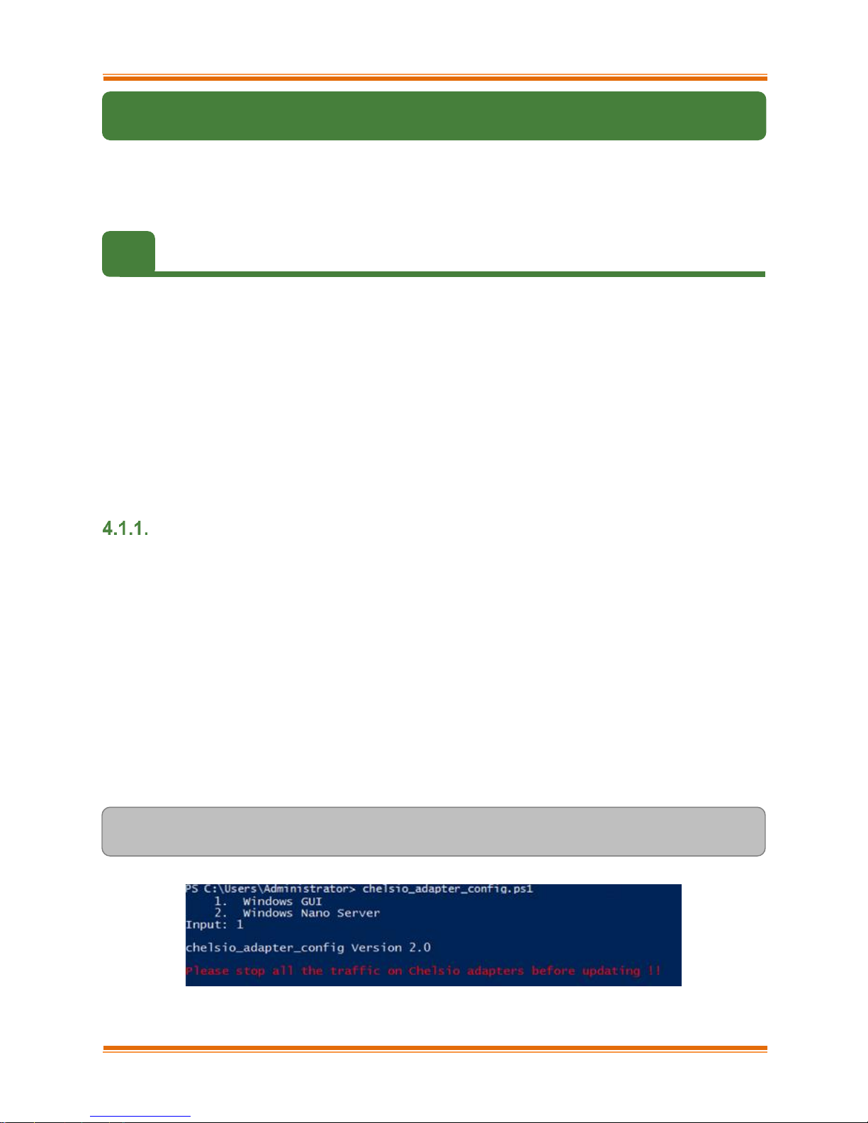
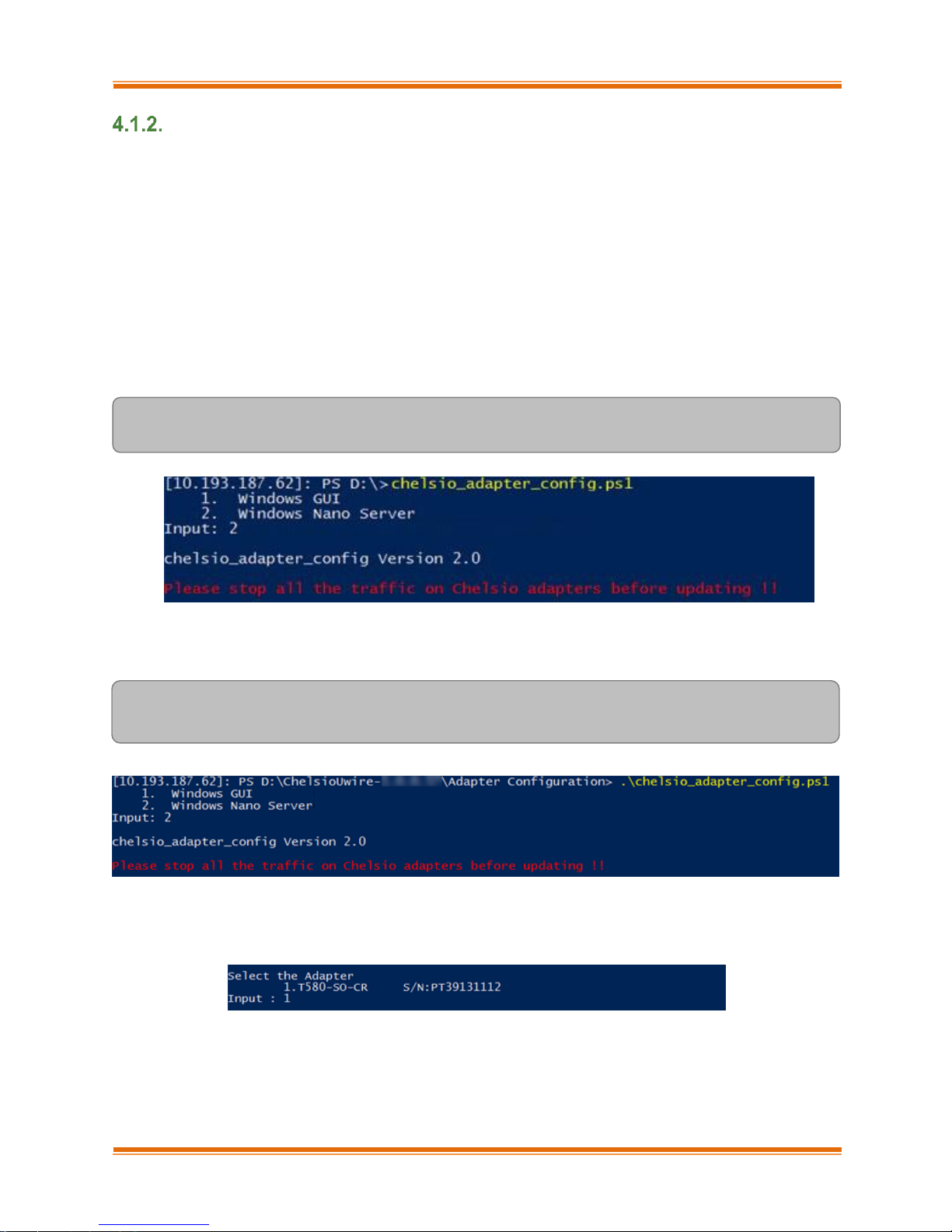
iii. Run the adapter configuration script and select Windows GUI (option 1) as the Windows
version. Hit [Enter].
Installer:
PS C:\Users\Administrator> chelsio_adapter_config.ps1
Figure 16 - Adapter configuration utility (Installer)
Page 27
Chapter I. Chelsio Unified Wire
Chelsio T5 Unified Wire for Windows 27
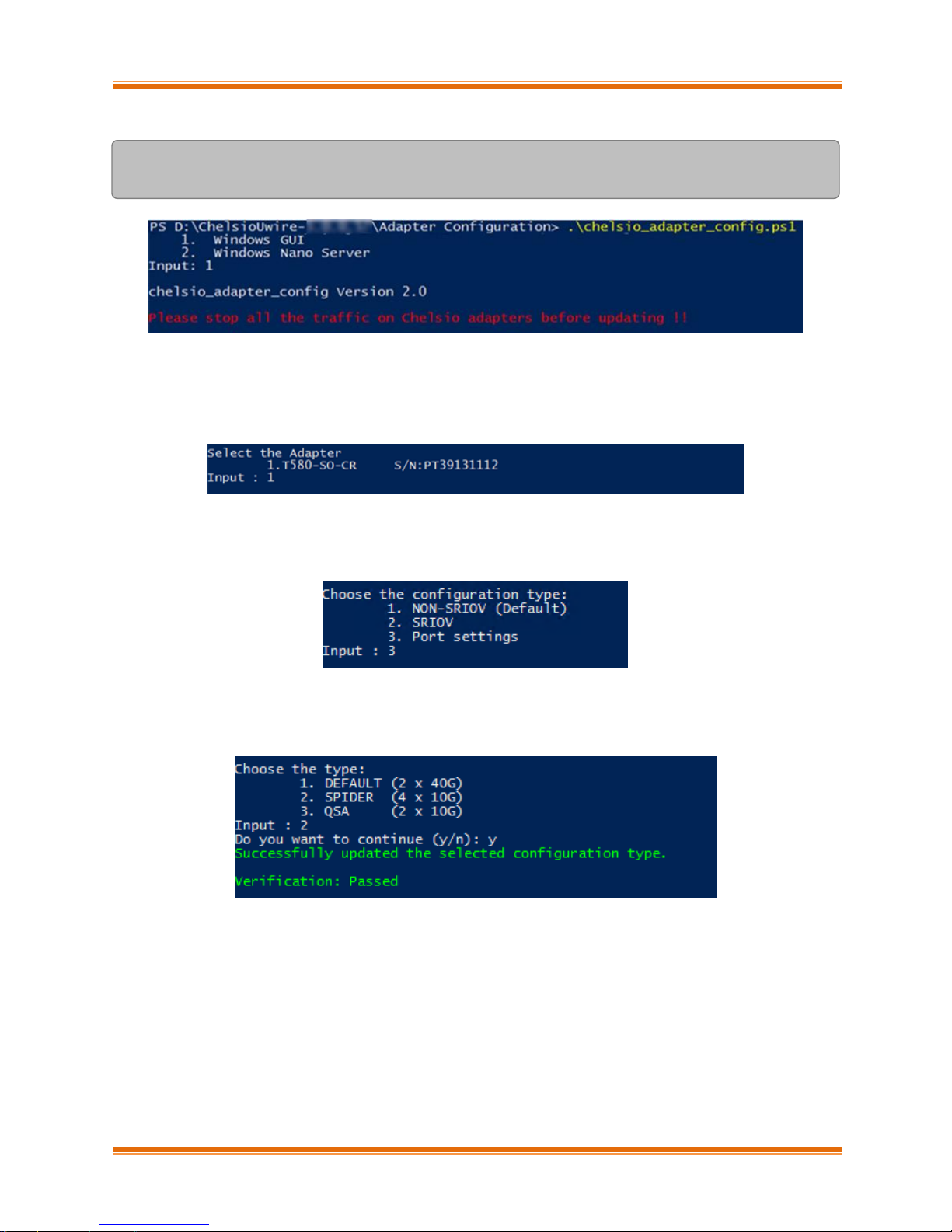
Zip Package:
PS D:\ChelsioUwire-x.x.x.xx\Adapter Configuration>
.\chelsio_adapter_config.ps1
Figure 17 - Adapter configuration utility (zip package)
iv. Enter the index of the 40G adapter for which the configuration needs to be updated. Hit
[Enter].
Figure 18 - Selecting adapter
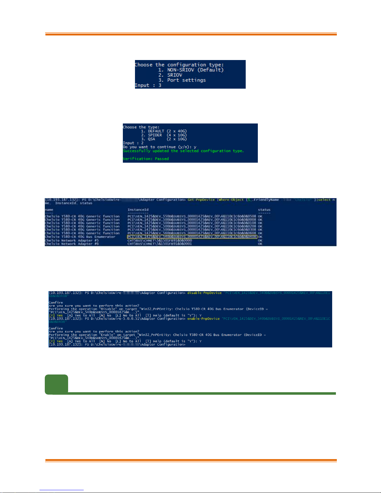
v. Select Port settings (option 3) as the configuration type. Hit [Enter].
Figure 19 - Port settings
vi. Select the operation mode and then enter y to confirm.
Figure 20 - Operation mode
vii. Open Device Manager, click on System Devices and right-click on the 40G Chelsio
adapter selected in step (iv).
viii. Select Disable and then Enable for changes to take effect.
Page 28
Chapter I. Chelsio Unified Wire
Chelsio T5 Unified Wire for Windows 28
Nano Server Machine (Nano Server Installer & Zip Package)
i. Connect to Nano Server Machine.
ii. In case of Nano Server Installer, the configuration script and cxgbnano.exe utility will be
copied to <system_drive>\Windows\System32 during installation.
If you are using the zip package, copy cxgbnano.exe from ChelsioUwire-x.x.x.xx folder to
<system_drive>\Windows\System32 and change your working directory to ChelsioUwire-
x.x.x.xx\Adapter Configuration.
iii. Run the adapter configuration script and select Windows Nano Server (option 2) as the
Windows version. Hit [Enter].
Nano Server Installer:
[nanomachine-ip]: PS D:\> chelsio_adapter_config.ps1
Figure 21 - Adapter configuration utility (Nano Server Installer)
Zip Package:
[nanomachine-ip]: PS D:\ChelsioUwire-x.x.x.xx\Adapter Configuration>
.\chelsio_adapter_config.ps1
Figure 22 - Adapter configuration utility (zip package)
iv. Enter the index of the 40G adapter for which the configuration needs to be updated
Figure 23 - Selecting adapter
Page 29
Chapter I. Chelsio Unified Wire
Chelsio T5 Unified Wire for Windows 29
v. Select Port settings (option 3) as the configuration type. Hit [Enter].
Figure 24 - Port settings
vi. Select the operation mode and then enter y to confirm.
Figure 25 - Operation mode
vii. Determine the Instance ID of the adapter using the Get-PnpDevice command:
Figure 26 - Adapter instance IDs
viii. Use the Instance ID obtained from the previous step to disable and enable the adapter for
changes to take effect.
Figure 27 - Committing changes
4.2. Assigning IP address
i. Double click on the Network Connections icon and choose the Chelsio card entry and
double click it.
ii. Click on the Properties button from the Local Area Connection X Status.
iii. Select “Internet Protocol (TCP/IP)” from the list and click on Properties button below it.
Page 30

Chapter I. Chelsio Unified Wire
Chelsio T5 Unified Wire for Windows 30
iv. From the Internet Protocol (TCP/IP) Properties window, assign an IP Address (e.g.
192.169.1.10) and subnet mask (e.g. 255.255.255.0).
v. Click on Ok and close on the other window.
vi. Check to see if you can ping to some other address on this subnet.
Page 31

Chapter I. Chelsio Unified Wire
Chelsio T5 Unified Wire for Windows 31
5. Mass Deployment (Installer)
Using Unified Wire Installer’s Mass Deployment feature, you can flash or erase Option ROM on
multiple systems (nodes) simultaneously. The Installer utilizes Unified Wire Manager’s Agent
and Client components to implement this feature. The Client component has to be installed on
the host machine and the Agent component on the remote nodes.
5.1. Pre-deployment Configuration
A configuration file containing directives is required by the Installer during installation, flashing
and erasing option ROM. Follow the steps mentioned below to generate and configure the file:
i. Copy the Unified Wire Installer (ChelsioUwire-x.x.x.xx.exe) to a shared location accessible
to all the nodes.
ii. Open Windows PowerShell with administrative privileges (right-click and select Run as
Administrator) and run the following command:
PS C:\Users\Administrator> .\ChelsioUwire-x.x.x.xx.exe -sampleconfig
The above command will generate a sample configuration file, RemoteMachineconfig.txt. It
contains the following directives:
StartShareMachineInfo
ExecutablePath:\\<Machine-IP>\<Shared directory>\ChelsioUwire-x.x.x.xx.exe
User:<user>
Password:<password>
EndShareMachineInfo
StartOfCluster
<user>:<Password>
<IPAddress1>
<IPAddress2>
<IPAddress3>
<IPAddressN>
EndOfCluster
Page 32

Chapter I. Chelsio Unified Wire
Chelsio T5 Unified Wire for Windows 32
StartOfNonCluster
<IPAddress1>:<user1>:<Password1>
<IPAddress2>:<user2>:<Password2>
<IPAddress3>:<user3>:<Password3>
<IPAddressN>:<userN>:<PasswordN>
EndOfNonCluster
iii. Open the configuration file and provide the following values:
a. Enter absolute path of the shared location where installer is copied to, for the
ExecutablePath parameter.
b. Provide user credentials for the User and Password parameters of the machine where
Installer was copied to.
c. Provide IP addresses of remote nodes between the StartOfCluster and EndOfCluster
tags. Enter each node’s IP address per line. If same user credentials are set for all the
nodes, enter them after the StartOfCluster tag, separated by a colon.
E.g.:
StartOfCluster
admin:pass123
10.193.184.63
10.193.184.62
.
.
EndOfCluster
For machines with different user credentials, enter each node’s IP address and
corresponding user credentials per line between the StartOfNonCluster and
EndOfNonCluster tags in the following format.
E.g.:
10.193.184.76:admin:pass789
10.193.184.78:admin:pass_456
iv. Save the file to a desired location.
For successful deployment of UM components and flashing/erasing option ROM,
please ensure that the host machine and remote nodes are in the same domain.
Note
Page 33

Chapter I. Chelsio Unified Wire
Chelsio T5 Unified Wire for Windows 33
5.2. Flashing Option ROM
Option ROM can be flashed using two methods. Both methods involve deployment of UM
components.
Deploying components and Flashing Option ROM together.
Deploying components and Flashing Option ROM separately.
Unified Wire Installer will flash Option ROM onto the first Chelsio adapter
present in remote node (adapter with index 0. See Configuring using UM CLI
to determine adapter index). Hence, ensure that you either use a non-Chelsio
adapter for corporate/private network or ensure that the Chelsio adapter used
is not installed as first on remote nodes.
Important
Both methods mentioned above will flash option ROM only onto the first Chelsio
adapter present in the remote node. If you plan to flash more adapters in the same
node or add new nodes to the cluster, they will have to be added as members to a
group and flashed using UM’s CLI component. See Configuring using UM CLI
for instructions.
Flashing option ROM on remote nodes with inbox NDIS drivers will fail. Hence,
please ensure that all nodes are updated to the latest version using the Unified
Wire Installer.
Note
Page 34

Chapter I. Chelsio Unified Wire
Chelsio T5 Unified Wire for Windows 34
Deploying UM components and Flashing Option ROM together
i. Run the following command to invoke the UM installer.
PS C:\Users\Administrator> .\ChelsioUwire-x.x.x.xx.exe -action
flashoptionrom -config <config_file.txt>
ii. Click the Next button for the Chelsio End User License Agreement Window.
Figure 28 - UM Installer welcome window
Page 35

Chapter I. Chelsio Unified Wire
Chelsio T5 Unified Wire for Windows 35
iii. Select the radio button I accept the terms of the license agreement and click Next.
Figure 29 - Chelsio EULA window
iv. The next window will display the pre-requisites for various UM components. Ensure that they
are met before proceeding. Click Next.
Figure 30 - UM prerequisites window
Page 36
Chapter I. Chelsio Unified Wire
Chelsio T5 Unified Wire for Windows 36
v. Now, select Custom radio button to customize the installation. Click Next.
Figure 31 - UM prerequisites window
vi. The next window will display the location where UM will be installed by default. You can
change the location by using the Change button or click Next to continue with the default
path.
Figure 32 - Changing UM installation path
Page 37
Chapter I. Chelsio Unified Wire
Chelsio T5 Unified Wire for Windows 37
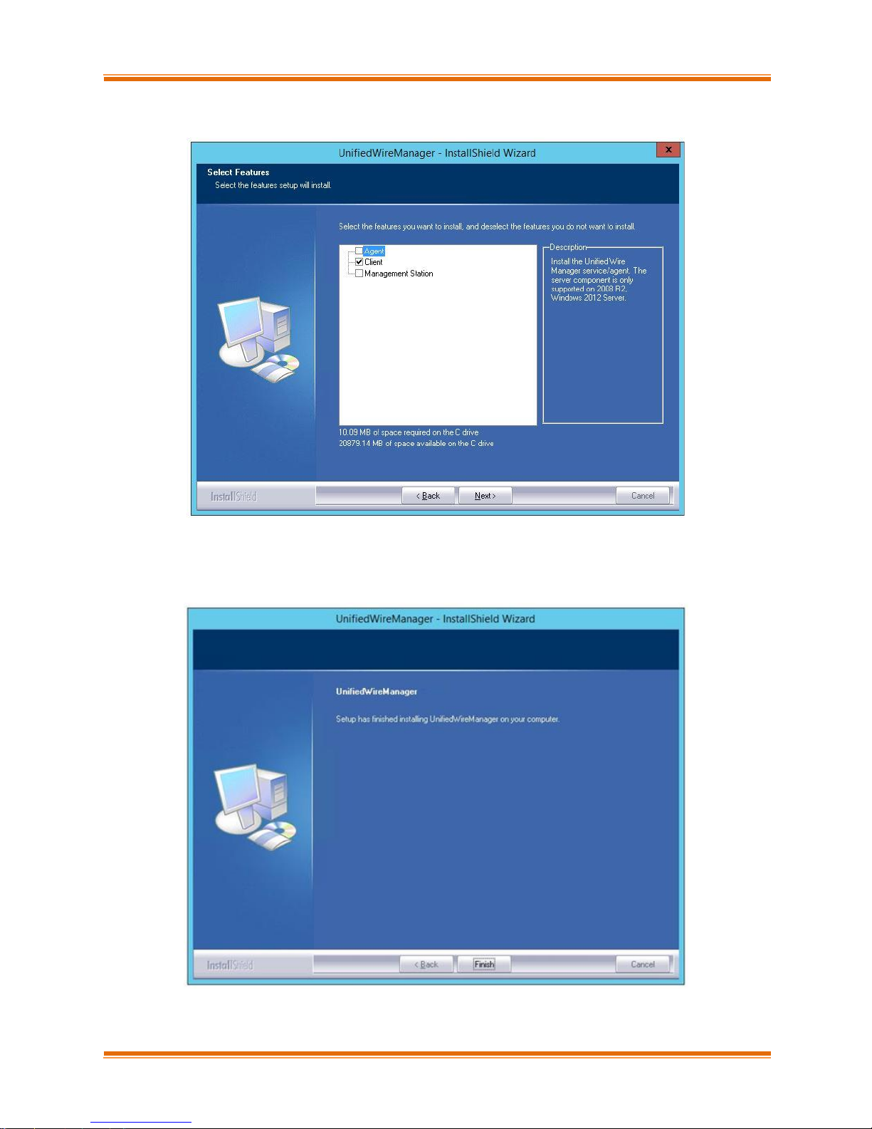
vii. Next, ensure that only Client is selected under features to be installed. Click Next.
Figure 33 - Selecting UM components
viii. Click Finish to complete Client installation.
Figure 34 - Finishing UM installation
Page 38

Chapter I. Chelsio Unified Wire
Chelsio T5 Unified Wire for Windows 38
ix. Now, installation of UM Agent component on remote nodes will commence.
Figure 35 - Starting Agent installation
x. Click Agree on the PsExec License Agreement window that appears. This window will
appear only during first installation.
Figure 36 - PsEXec license agreement
Page 39
Chapter I. Chelsio Unified Wire
Chelsio T5 Unified Wire for Windows 39
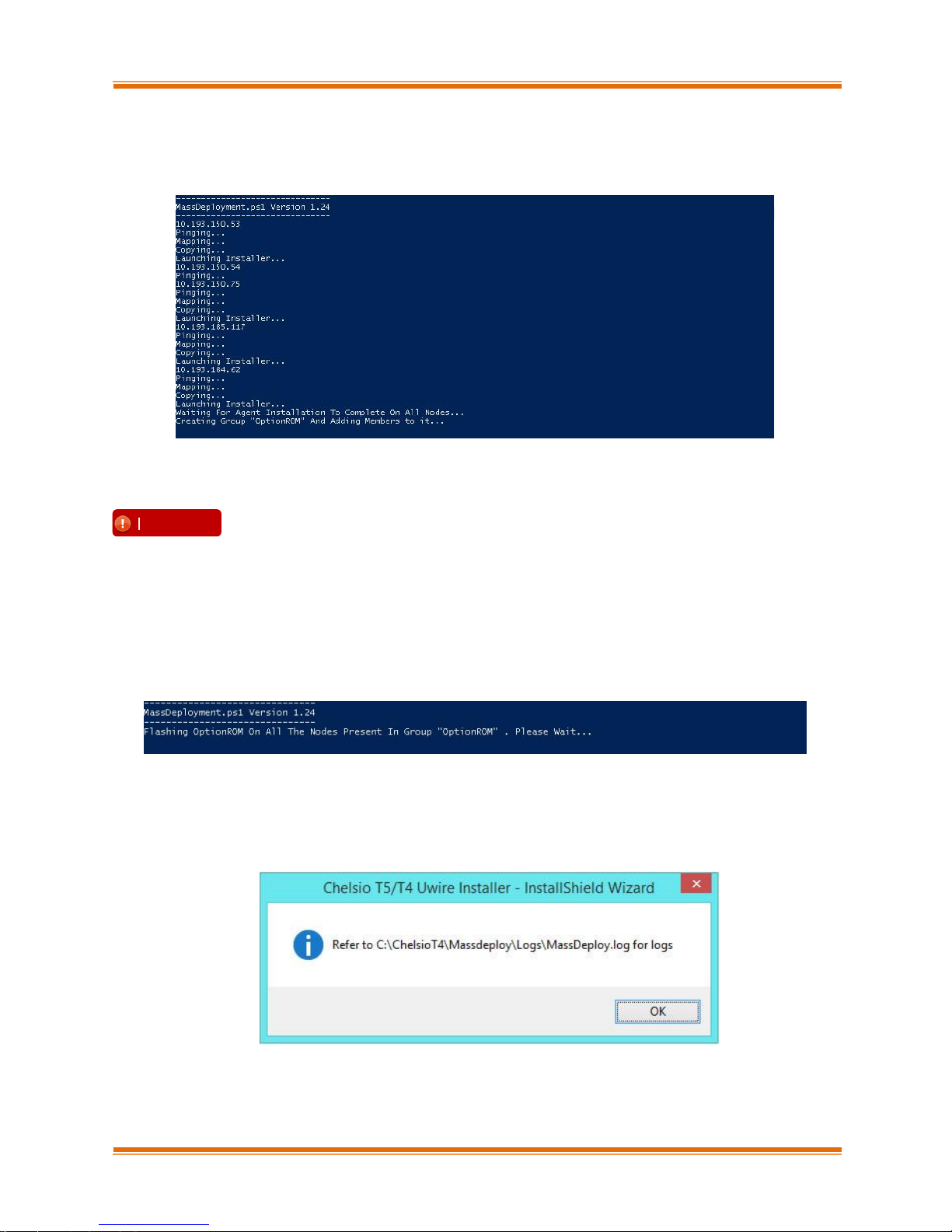
xi. UM Agents will now be installed on remote nodes. A default group OptionROM will be created
and all the nodes on which UM Agent was successfully installed, will be added to it as
members.
Figure 37 - Agent installation on remote nodes
xii. Option ROM will now be flashed onto adapters on remote nodes present in the OptionROM
group.
Figure 38 - Flashing option ROM
xiii. After completion, a log file MassDeploy.log containing the summary of the process will be
created. Click OK on the dialog box that appears to exit the installer and view the log.
Figure 39 - Finishing option ROM flashing
Please ensure that the OptionROM group created here is not deleted. Also,
UM Client component should not be un-installed. Doing so will cause
flashing/erasing Option ROM to fail on remote nodes. UM components will
have to be deployed again to fix this issue.
Important
Page 40

Chapter I. Chelsio Unified Wire
Chelsio T5 Unified Wire for Windows 40
Deploying UM components and Flashing Option ROM separately
Deploying UM Components
i. Run the following command to invoke the Unified Wire Installer.
PS C:\Users\Administrator> .\ChelsioUwire-x.x.x.xx.exe -action deployagent
–config <config_file.txt>
ii. Follow steps (ii)-(xi) in the Deploying UM components and Flashing Option ROM
together section.
iii. After completion, a log file MassDeploy.log containing the summary of the process will be
created. Click OK on the dialog box that appears to exit the installer and view the log.
Figure 40 - Finishing UM components deployment
Flashing Option ROM
i. Run the following command to flash Option ROM:
PS C:\Users\Administrator> .\ChelsioUwire-x.x.x.xx.exe –action
flashoptionrom
ii. Flashing Option ROM is possible only if UM Agents were installed on nodes using this
installer. Click Yes to continue.
Figure 41 - Starting option ROM flashing
Page 41

Chapter I. Chelsio Unified Wire
Chelsio T5 Unified Wire for Windows 41
iii. Follow steps xii and xiii in the Deploying UM components and Flashing Option ROM
together section.
5.3. Erasing Option ROM
i. To erase OptionROM from adapters on all the nodes, run the following command:
PS C:\Users\Administrator> .\ChelsioUwire-x.x.x.xx.exe -action
eraseoptionrom
ii. Erasing OptionROM is possible only if the adapters were flashed using this installer. Click
Yes to continue.
Figure 42 - Starting option ROM erasing
iii. Option ROM will now be erased from adapters on nodes present in the OptionROM group.
Figure 43 - Erasing option ROM on remote nodes
iv. After completion, a log file MassDeploy.log containing the summary of the process will be
created. Click OK on the dialog box that appears to exit the installer and view the log.
Unified Wire Installer will erase option ROM only from the first Chelsio adapter present
in the remote node. If you plan to erase from more adapters in the same node or add
new nodes to the cluster, they will have to be added as members to a group and erased
using UM’s CLI component. See Configuring using UM CLI for instructions.
Note
Flashing option ROM on remote nodes with inbox NDIS drivers will fail. Hence, please
ensure that all nodes are updated to the latest version using the Unified Wire Installer.
Note
Page 42

Chapter I. Chelsio Unified Wire
Chelsio T5 Unified Wire for Windows 42
Figure 44 - Finishing option ROM erasing
5.4. Configuring using UM CLI
Configuring groups and members
You can manage multiple groups and members using Unified Wire Manager’s CLI component,
chelsio_uwcli.
Create Group
To create a new group, run the following command:
PS C:\Users\Administrator> chelsio_uwcli.exe –m creategroup
grpname=<new_group_name> OSType=windows GroupType=t4adapter
E.g.
PS C:\Users\Administrator> chelsio_uwcli.exe –m creategroup grpname=flash
OSType=windows GroupType=t4adapter
Figure 45 - Creating group
To use the CLI component, you will have to change your working directory to the
location where UM Client is installed. Typically, this will be C:\Program Files
(x86)\Chelsio Communications\UnifiedWireManager\client. To avoid this and run
the command from any path, you will need to reboot the host. The following examples
assume that the host machine was rebooted before running commands.
Note
Page 43

Chapter I. Chelsio Unified Wire
Chelsio T5 Unified Wire for Windows 43
Add member to group
To add a member to a group, run the following command:
PS C:\Users\Administrator> chelsio_uwcli.exe –m addmember
grpname=<group_name>
details=”<IP_address>;<user_id>;<password>;*;*,*,<adapter_index>,*,*,*,*,*>”
E.g.
PS C:\Users\Administrator> chelsio_uwcli.exe –m addmember grpname=OptionROM
details=”10.193.185.107;administrator;cdrom888;*;*,*,0,*,*,*,*,*>”
Figure 46 - Adding member to group
View group and member details
To view details of all the groups and members created, run the following command:
PS C:\Users\Administrator> chelsio_uwcli.exe –m list
Figure 47 - Viewing group and member details
Page 44
Chapter I. Chelsio Unified Wire
Chelsio T5 Unified Wire for Windows 44
Delete member from a group
To delete a member from a group, run the following command:
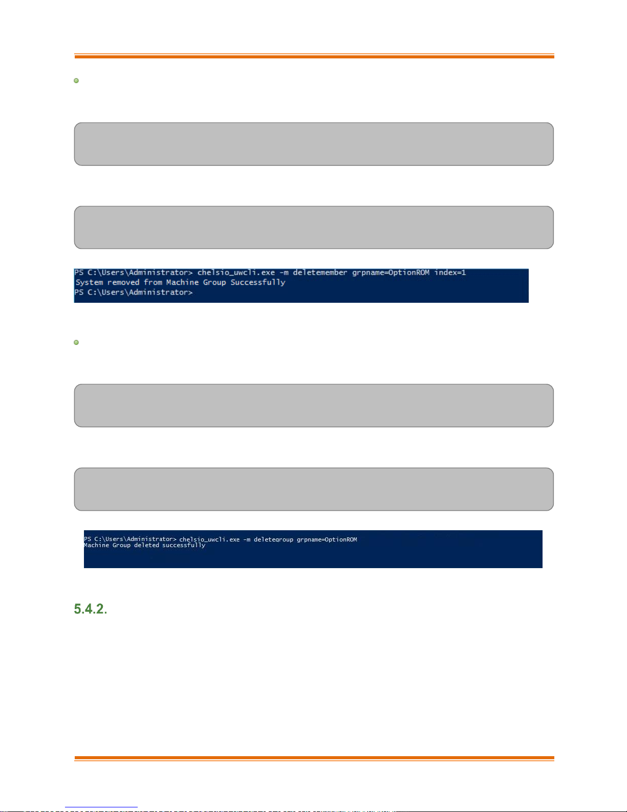
PS C:\Users\Administrator> chelsio_uwcli.exe –m deletemember
grpname=<group_name> index=<member_index>
E.g.
PS C:\Users\Administrator> chelsio_uwcli.exe –m deletemember
grpname=OptionROM index=1
Figure 48 - Deleting member from group
Delete Group
To delete a group, run the following command:
PS C:\Users\Administrator> chelsio_uwcli.exe –m deletegroup
grpname=<group_name>
E.g.
PS C:\Users\Administrator> chelsio_uwcli.exe –m deletegroup
grpname=OptionROM
Figure 49 - Deleting group
Flashing/Erasing Option ROM
Apart from Unified Wire Installer, you can also use Unified Wire Manager’s CLI component
(chelsio_uwcli) to flash or erase Option ROM on multiple nodes. This is particularly useful when
you need to flash/erase Option ROM on groups other than the default OptionROM group.
Page 45

Chapter I. Chelsio Unified Wire
Chelsio T5 Unified Wire for Windows 45
Flashing Option ROM
To flash Option ROM using UM, run the following command:
PS C:\Users\Administrator> chelsio_uwcli.exe chelsio flashrom
adapter=BULKADAPTER path=<path_to_optionrom_image_file> –B <group_name>
E.g.
PS C:\Users\Administrator> chelsio_uwcli.exe chelsio flashrom
adapter=BULKADAPTER path=C:\Users\Administrator\Desktop\cuwlbt4.bin –B
OptionROM
Figure 50 - Flashing option ROM using UM CLI
Viewing status
You can list the adapters on local host and verify if Option ROM was successfully flashed
using the following command:
PS C:\Users\Administrator> chelsio_uwcli.exe chelsio listadapters –B
<group_name>
E.g.
PS C:\Users\Administrator> chelsio_uwcli.exe chelsio listadapters –B
OptionROM
Flashing option ROM on remote nodes with inbox NDIS drivers will fail. Hence, please
ensure that all nodes are updated to the latest version using the Unified Wire Installer.
Note
Page 46

Chapter I. Chelsio Unified Wire
Chelsio T5 Unified Wire for Windows 46
Figure 51 - Viewing status
Erasing Option ROM
To erase Option ROM using UM, run the following command:
PS C:\Users\Administrator> chelsio_uwcli.exe chelsio eraserom
adapter=BULKADAPTER force=1 –B <group_name>
In addition to flashing and erasing Option ROM, you can perform additional bulk operations on
remote nodes like setting MTU and VLAN ID, changing adapter and port parameters, etc. To
know more about these options available, run the following command:
PS C:\Users\Administrator> chelsio_uwcli.exe -
Figure 52 - Erasing option ROM using UM CLI
Page 47

Chapter I. Chelsio Unified Wire
Chelsio T5 Unified Wire for Windows 47
Help
To view Unified Wire Manager’s CLI help, run the following command:
PS C:\Users\Administrator> chelsio_uwcli.exe –m
Page 48

Chapter I. Chelsio Unified Wire
Chelsio T5 Unified Wire for Windows 48
6. cxgbtool/cxgbnano help
The cxgbtool (cxgbnano for Nano Server) command queries or sets various aspects of Chelsio
network interface cards. It complements standard tools used to configure network settings and
provides functionality not available through such tools.
Some of the commands provided can be used to query running statistics to aid in debugging.
Definitions
[nicInterface] is the name of the network device to work on, given in the format "nic[0,1,..n]"
[vbdInterface] is the name of the Chelsio Bus Enumerator instance to work on, given in the format
"vbd[0,1,...n]"
Syntax
cxgbtool [vbdInterface|nicInterface][parameters][(optionalParameters)]
In case of Nano Server, run the commands using cxgbnano instead of cxgbtool, i.e.,
cxgbnano [vbdInterface|nicInterface][parameters][(optionalParameters)]
-h
Description: Displays help
Syntax: cxgbtool -h
cim_la
Decription: Displays results of logic analyzer trace.
Syntax: cxbtool [vbdInterface] cim_la
Example:
Page 49
Chapter I. Chelsio Unified Wire
Chelsio T5 Unified Wire for Windows 49
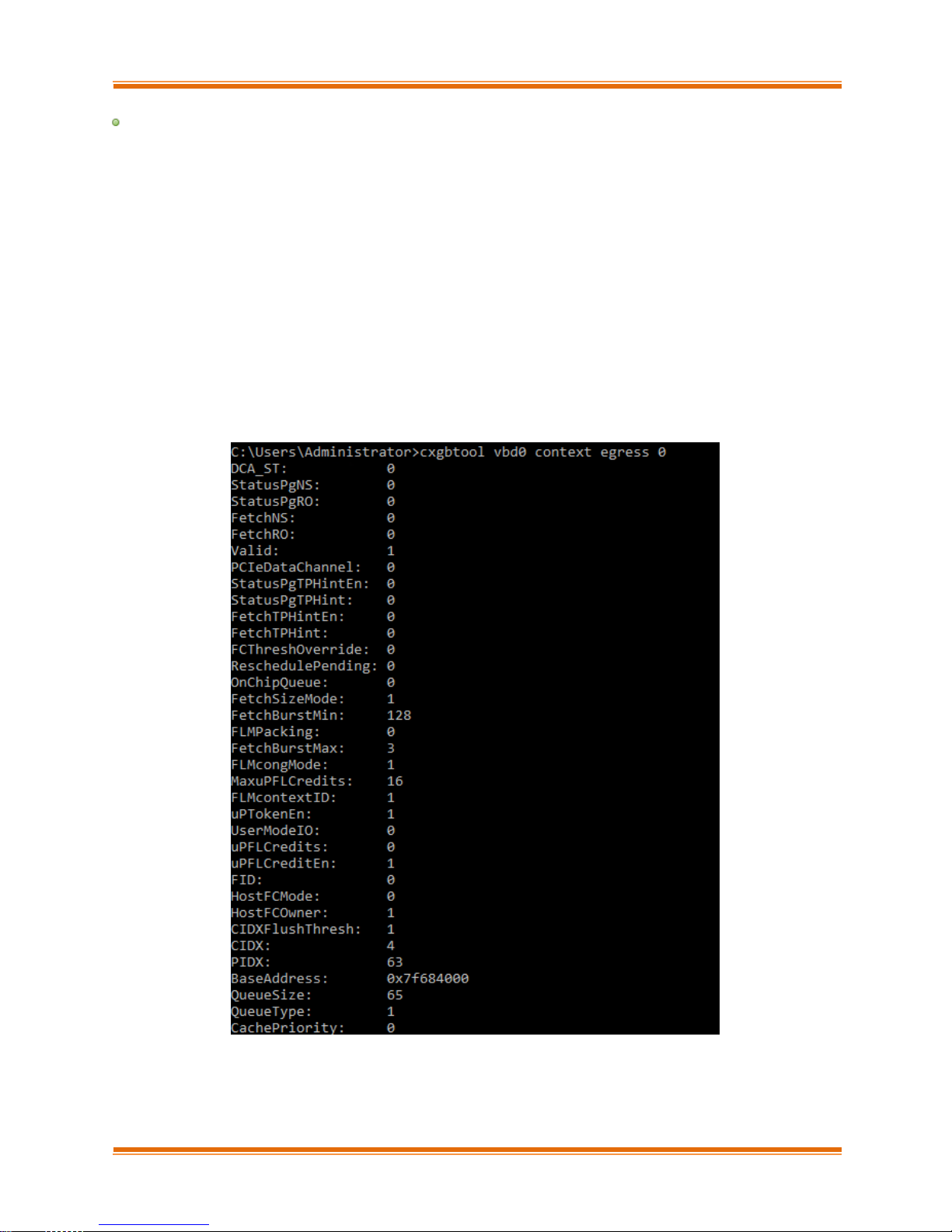
context
Description: Shows an SGE context.
Syntax: cxgbtool [vbdInterface] context [contextType] [queueId]
Context Type Parameters:
Egress: Egress queue context.
fl: Free list manager context.
response: Response queue context.
ingress: Ingress queue context.
cq: RDMA completion queue context.
cong: Congestion context.
Example:
Page 50

Chapter I. Chelsio Unified Wire
Chelsio T5 Unified Wire for Windows 50
filter
Description: Displays list of configured hardware filters
Syntax: cxgbtool [nicInterface] filter
Example:
loadfw
Description: Loads firmware image.
Syntax: cxgbtool [vbdInterface] loadfw [firmwareImage]
Example:
loadcfg
Description: Loads firmware configuration file or clears configuration flash region.
Syntax: cxgbtool [vbdInterface] loadcfg [[firmwareConfigurationFile]|clear]
Example:
Loading T5 firmware configuration file:
Clearing the configuration file region in flash
The configuration file used must be in text format and not a header file.
Note
The Firmware input file used must be a binary and not a header file.
Note
Page 51

Chapter I. Chelsio Unified Wire
Chelsio T5 Unified Wire for Windows 51
loadphy
Description: Loads phy firmware.
Syntax: cxgbtool [vbdInterface] loadphy [phyFile]
Example:
loadboot
Description: Flashes the Option ROM image.
Syntax: cxgbtool [vbdInterface] loadboot [bootImageFile] [pf {0|1|2|…|7}|offset {val}|clear]
Parameters:
pf{val}: Flash Option ROM image to the offset defined by the PFs EXPROM_OFST in the serial
configuration.
offset {val}: Flash Option ROM image to the offset specified by the user.
clear: The flash area reserved for Option ROM image will be cleared.
Example:
Flashing Option ROM image to the offset defined by the PFs EXPROM_OFST:
Flashing Option ROM image to user specified offset:
loadboot-cfg
Description: Loads boot configuration file.
Syntax: cxgbtool [vbdInterface] loadboot-cfg [[bootConfigImageFile]|clear]
Parameters:
clear: The flash area reserved for boot configuration file will be cleared.
Page 52

Chapter I. Chelsio Unified Wire
Chelsio T5 Unified Wire for Windows 52
Example:
Loading boot configuration file:
Clearing the flash area:
mdio
Description: Reads/writes MDIO register.
Syntax: cxgbtool [vbdInterface] mdio
[physicalAddress][manageableDevicesAddress][registerAddress] [(writeValue)]
Example
Read MDIO register
Write MDIO register currently not supported.
Note
Page 53

Chapter I. Chelsio Unified Wire
Chelsio T5 Unified Wire for Windows 53
meminfo
Description: Displays memory info.
Syntax: cxgbtool [vbdInterface] meminfo
Example:
mtus
Description: Prints hardware MTU table.
Syntax: cxgtool [vbdInterface] mtus
Page 54

Chapter I. Chelsio Unified Wire
Chelsio T5 Unified Wire for Windows 54
Example:
qsets
Description: Reads # of qsets
Syntax: cxgbtool [nicInterface] qsets
Example:
qstats
Description: Displays statistics for each Tx & Rx queue.
Syntax: cxgbtool [nicInterface] qstats [queueType [(clr)]]
Queue Type parameters:
txeth: Tx tunnel queue statistics.
rxeth: Rx tunnel queue statistics.
txvmq: Tx VM queue statistics.
rxvmq: Rx VM queue statistics.
txrdma: RDMA Tx queue statistics.
rxrdma: RDMA Rx queue statistics.
txctrl: Chimney control queue statistics.
txfwd: Chimney forwarding queue statistics.
txnvgre: Tx NVGRE statistics.
rxnvgre: Rx NVGRE statistics.
clr: Clear Queue statistics.
Page 55

Chapter I. Chelsio Unified Wire
Chelsio T5 Unified Wire for Windows 55
Example of rxeth qstats:
reg
Description: Reads/writes register.
Syntax:
Register Read: cxgbtool [vbdInterface] reg [readAddress]
Register Write: cxgbtool [vbdInterface] reg [[writeAddress] = {val}]
Example:
Register read:
Register write:
regdump
Description: Displays registers of a hardware module. Not specifying any parameter will display
registers for all the modules. Not all modules are available on all adapters.
Syntax:
Display registers for all available modules: cxgbtool [vbdInterface] regdump
Page 56

Chapter I. Chelsio Unified Wire
Chelsio T5 Unified Wire for Windows 56
Display registers for specific module: cxgbtool [vbdInterface] regdump [registerModule]
Table 1 – T5 register module parameters
Module Parameter
Description
sge
Scatter-Gather DMA Engine common register set.
pci
PCI Express Interface common register set. This module implements
the PCI-Express SR-IOV physical logical, data link, and transaction
layers.
dbg
Debug Engine Common register set.
mc0
Memory controller 0 common register set. This module implements the
memory controller for the optional external DDR-II/DDR-III SDRAM.
mc1
Memory controller 1 common register set. This module implements the
memory controller for the optional external DDR-II/DDR-III SDRAM.
ma
Memory Arbiter common register set. This module implements the
arbitration of memory requests from the various on-chip sources to the
memory hierarchy consisting of on-chip eDRAM, external DDR2/DDR3
memory, and host memory that is accessed through the PCIe.
edc0
eDRAM and Controller 0 common register set. This is the on-chip
eDRAM and controller.
edc1
eDRAM and Controller 1 common register set. This is the on-chip
eDRAM and controller.
cim
CIM common register set. This module implements the CPU interface
and μP is the embedded microprocessor. The CIM incorporates
functions to improve the performance of CPU accesses to external
memory.
tp
Transport Protocol Engine common register set. This module
implements the main packet processing pipeline.
ulp_rx
Ingress Upper Layer Protocol common register set. This module
implements the upper layer protocol processing in the ingress direction
for protocols that are layered on top of TCP, such as iSCSI and RDMA.
ulp_tx
Egress Upper Layer Protocol common register set. This module
provides Upper Layer support for RDMA and iSCSI offload in the
transmit direction, and also implements LSO/TSO functionality.
pmrx
Ingress Payload Manager common register set. These modules
implement the payload manager for receive/ingress.
pmtx
Egress Payload Manager common register set. These modules
implement the payload manager for transmit/egress.
mps
Multi-port support common register set. This module implements the
multi-port support for T4, and switches egress packets to the ingress
path when their Ethernet DA (Destination Address) matches an address
in the exact match Ethernet Address database, or if the outer-VLAN
indicates that the packet is destined to another virtual machine
connected to the T4, or if another virtual machine is subscribing to an
L2 multicast group that is the MAC destination address of the packet.
cplsw
CPL Switch common register set. This module implements a
configurable switch for ingress CPL messages to the SGE and/or CIM.
The embedded μP is assigned a receive queue number and can be
assigned one or more MAC addresses and IP addresses, and any of
these can be used to switch ingress packets to the μP for processing.
Page 57

Chapter I. Chelsio Unified Wire
Chelsio T5 Unified Wire for Windows 57
smb
System Management Bus common register set. This module
implements an SMBus Master/Slave for system management.
i2c
I2C-Bus Master common register set. This module implements an I2CBus Master for PHY management and I/O expansion.
mi
MI common register set. This module implements an MDIO Master for
PHY management.
uart
pmu
Power Management Unit common register set. Power management
unit.
sf
Serial Flash controller common register set. This module implements
the serial flash controller. It interfaces to the external serial flash device.
pl
PIO Local Bus controller common register set. This module implements
the PIO Local Bus controller. It is physically distributed across T4/T5.
le
Lookup Engine Common register set. The Lookup Engine implements
the connection, filter and ACL databases. This module includes a TCAM
Memory controller that interfaces with the on-chip TCAM memory array,
and it implements the interface to the external memory that is used to
scale the support of the connection database to 1M connections. The
LE stores ACL rules, it stores routing information to handle routing for
SYN-cookie mode offloaded listening servers, and it stores tuple
information for offloaded connections, and FCoE exchanges.
ncsi
Network Controller sideband Interface common register set. The
module implements the NCSI (Network Controller Sideband Interface)
protocol.
xgmac
mac
MAC common register set.
hma
Example:
Displaying all available module registers:
Page 58

Chapter I. Chelsio Unified Wire
Chelsio T5 Unified Wire for Windows 58
Displaying specific (mps) module registers:
tcb
Description: Reads hardware TCP Control Block, which contains details regarding all offloaded
connections.
Syntax: cxgbtool [nicInterface] tcb [tid]
Example:
Page 59

Chapter I. Chelsio Unified Wire
Chelsio T5 Unified Wire for Windows 59
tpi
Description: Displays TP indirect registers.
Syntax: cxgbtool [vbdInterface] tpi
Example:
Page 60

Chapter I. Chelsio Unified Wire
Chelsio T5 Unified Wire for Windows 60
sgedbg
Description: Displays sge debug indirect registers.
Syntax: cxgbtool [vbdInterface] sgedbg
Example:
Page 61

Chapter I. Chelsio Unified Wire
Chelsio T5 Unified Wire for Windows 61
dumpctx
Description: Displays adapter context.
Syntax: cxgbtool [nicInterface] dumpctx
Example:
version
Description: Displays the adapter Part Number, Serial Number, Device ID, Firmware Version,
TP, NDIS Driver version, and VBD version.
Syntax: cxgbtool [vbdInterface] version
Example:
Page 62

Chapter I. Chelsio Unified Wire
Chelsio T5 Unified Wire for Windows 62
fwtoc
Description: Converts firmware binary file to source file header.
Syntax: cxgbtool [vbdInterface] fwtoc [firmwareFile] filename= [CFileName].bin
Example:
inst
Description: Installs driver package specified in the setup information file (.inf).
Syntax: cxgbtool [vbdInterface] inst [infFilePath] force
Example:
unins
Description: Uninstalls driver package specified in the setup information file (.inf).
Syntax: cxgbtool [vbdInterface] uninst [infFile]
Example:
Page 63

Chapter I. Chelsio Unified Wire
Chelsio T5 Unified Wire for Windows 63
update
Description: Updates driver package.
Syntax: cxgbtool update [infFile]
Example:
rescan all
Description: Scans for hardware changes in the device manager.
Syntax: cxgbtool [vbdInterface] rescan all
Example:
trace
Description: Enables driver debug prints.
Syntax: trace [nicInterface|vbdInterface] trace [nic|vbd] [(flags)][(level)]
Example:
seeprom
Description: Reads/Writes SEEPROM (init+VPD) data.
Syntax:
Read SEEPROM data to a bin file: cxgbtool [vbdInterface] seeprom read
Display SEEPROM data in console: cxgbtool [vbdInterface] seeprom dump
Write SEEPROM data: cxgbtool [vbdInterface] seeprom write [seepromFile]
Verify SEEPROM data: cxgbtool [vbdInterface] seeprom verify [seepromFile]
Important
Use this option with caution. Incorrect usage may render the adapter useless.
Page 64

Chapter I. Chelsio Unified Wire
Chelsio T5 Unified Wire for Windows 64
Example:
Read SEEPROM data:
Write SEEPROM data:
Verify SEEPROM data:
serialinit
Description: Reads/Writes serialinit data.
Syntax:
Read serialinit data to a bin file: cxgbtool [vbdInterface] serialinit read
Display serialinit data in console: cxgbtool [vbdInterface] serialinit dump
Write serialinit data: cxgbtool [vbdInterface] serialinit write [initdataFile]
Verify serialinit data: cxgbtool [vbdInterface] serialinit verify [initdataFile]
Important
Use this option with caution. Incorrect usage may render the adapter useless.
The seepromFile should be in binary format (.bin).
Note
The initdataFile should be in binary format (.bin).
Note
Page 65

Chapter I. Chelsio Unified Wire
Chelsio T5 Unified Wire for Windows 65
Example:
Read serialinit data
Write serialinit data
Verify serialinit data
vpd
Description: Reads/writes VPD data.
Syntax:
Read VPD data: cxgbtool [vpdInterface] vpd read
Write VPD data to serial EEPROM on chip: cxgbtool [vpdInterface] vpd write [vpdFile]
Example:
Read VPD Data:
Important
Use this option with caution. Incorrect usage may render the adapter useless.
The vpdFile should be in binary format (.bin).
Note
Page 66

Chapter I. Chelsio Unified Wire
Chelsio T5 Unified Wire for Windows 66
Write VPD Data:
vpdparams
Description: Displays the adapters Serial Number, Device ID, EC, Core Clock, Part Number, and
Network Address (MAC).
Syntax: cxgbtool [vbdInterface] vpdparams
Example:
wtp
Description: Traces the Ingress and Egress path of a packet through the Chelsio adapter.
Syntax: cxgbtool [vbdInterface] wtp
Example:
Page 67

Chapter I. Chelsio Unified Wire
Chelsio T5 Unified Wire for Windows 67
stats
Description: Prints MAC statistics for a given port or TP MIB statistics.
Syntax: cxgbtool [vbdInterface] stats [mac{portInstance}|mib]
Example:
Page 68

Chapter I. Chelsio Unified Wire
Chelsio T5 Unified Wire for Windows 68
cpl_stats
Description: Displays CPL Request and Response Statistics for all channels.
Syntax: cxgbtool [vbdInterface] cpl_stats
Example:
debugfs
Description: When used in conjunction with other options, debugfs displays useful information
regarding Chelsio adapters.
Syntax: cxgbtool [vbdInterface] debugfs [option]
debugfs options:
cctrl
Description: Displays congestion control table.
Syntax: cxgbtool [vbdInterface] debugfs cctrl
Example:
Page 69

Chapter I. Chelsio Unified Wire
Chelsio T5 Unified Wire for Windows 69
cim_pif_la
Description: Displays CIM PIF logic analyzer trace.
Syntax: cxgbtool [vbdInterface] debugfs cim_pif_la
Example:
cim_ma_la
Description: Displays results of CIM MA logic analyzer trace.
Syntax: cxgbtool [vbdInterface] debugfs cim_ma_la
Example:
Page 70

Chapter I. Chelsio Unified Wire
Chelsio T5 Unified Wire for Windows 70
cim_qcfg
Description: Displays CIM queue configuration details.
Syntax: cxgbtool [vbdInterface] debugfs cim_qcfg
Example:
clk
Description: Displays the core clock.
Syntax: cxgbtool [vbdInterface] debugfs clk
Example:
sensor
Description: Displays sensor data.
Syntax: cxgbtool [nicInterface] debugfs sensor
Page 71

Chapter I. Chelsio Unified Wire
Chelsio T5 Unified Wire for Windows 71
Example:
ddp_stats
Description: Displays DDP(Direct Data Placement) statistics.
Syntax: cxgbtool [vbdInterface] debugfs ddp_stats
Example:
edc0
Description: Redirects EDC0 memory details to a file.
Syntax: cxgbtool [vbdInterface] debugfs edc0 [fileName]
Example:
edc1
Description: Redirects EDC1 memory details to a file.
Syntax: cxgbtool [vbdInterface] debugfs edc1 [fileName]
It is recommended that the fileName be provided without any extension.
Note
It is recommended that the fileName should be provided without any extension.
Note
Page 72

Chapter I. Chelsio Unified Wire
Chelsio T5 Unified Wire for Windows 72
Example:
flash
Description: Redirects Flash memory details to a file.
Syntax: cxgbtool [vbdInterface] debugfs flash [fileName]
Example:
ibq_tp
Description: Displays CIM TP inbound queue.
Syntax: cxgbtool [vbdInterface] debugfs ibq_tp[{0|1}]
Example:
It is recommended that the fileName should be provided without any extension.
Note
Page 73

Chapter I. Chelsio Unified Wire
Chelsio T5 Unified Wire for Windows 73
ibq_ulp
Description: Displays CIM ULP inbound queue.
Syntax: cxgbtool [vbdInterface] debugfs ibq_ulp
Example:
ibq_sge
Description: Displays CIM SGE inbound queue.
Syntax: cxgbtool [vbdInterface] debugfs ibq_sge[{0|1}]
Example:
Page 74

Chapter I. Chelsio Unified Wire
Chelsio T5 Unified Wire for Windows 74
ibq_ncsi
Description: Displays CIM NCSI inbound queue.
Syntax: cxgbtool [vbdInterface] debugfs ibq_ncsi
Example:
mc
Description: Redirects MC memory details to a file.
Syntax: cxgbtool [vbdInterface] debugfs mc[{0|1}] [dumpFileName]
Example:
mps_tcam
Description: Displays MPS TCAM configuration.
Syntax: cxgbtool [vbdInterface] debugfs mps_tcam
It is recommended that the dumpFileName should be provided without any extension.
Note
Page 75

Chapter I. Chelsio Unified Wire
Chelsio T5 Unified Wire for Windows 75
Example:
mps_trc_rd trace
Description: Reads MPS trace filter.
Syntax: cxgbtool [vbdInterface] debugfs mps_trc_rd trace[traceQueueId]
Example:
mps_trc_wr trace
Description: Sets MPS trace filter.
Syntax:
cxgbtool [vbdInterface] debugfs mps_trc_wr trace[0|1|2|3] [tx[portInstance]|rx[portInstance]]
Example:
Setting up trace0 with tx0 (tx0 is port0 Tx path)
Page 76

Chapter I. Chelsio Unified Wire
Chelsio T5 Unified Wire for Windows 76
mbox
Description: Displays the last command in each mailbox.
Syntax: cxgbtool [vbdInterface] debugfs mbox[{0|1|2|…|7}]
Example:
obq_ulp
Description: Displays ULP outbound queue.
Syntax: cxgbtool [vbdInterface] debugfs obq_ulp[{0|1|2|3}]
Example:
obq_sge
Description: Displays SGE outbound queue.
Syntax: cxgbtool [vbdInterface] debugfs obq_sge
Page 77

Chapter I. Chelsio Unified Wire
Chelsio T5 Unified Wire for Windows 77
Example:
obq_ncsi
Description: Displays NCSI outbound queue.
Syntax: cxgbtool [vbdInterface] debugfs obq_ncsi
Example:
obq_sge_rx_q
Description: Displays CIM SGE outbound queue.
Syntax: cxgbtool [vbdInterface] debugfs obq_sge_rx_q[{0|1}]
Page 78

Chapter I. Chelsio Unified Wire
Chelsio T5 Unified Wire for Windows 78
Example:
pm_stats
Description: Displays page memory statistics.
Syntax: cxgbtool [vbdInterface] debugfs pm_stats
Example:
tcp_stats
Description: Displays IPv4/IPv6 TCP statistics.
Syntax: cxgbtool [vbdInterface] debugfs tcp_stats
Example:
tp_err_stats
Description: Displays TP error statistics for channel 0-3.
Syntax: cxgbtool [vbdInterface] debugfs tp_err_stats
Page 79

Chapter I. Chelsio Unified Wire
Chelsio T5 Unified Wire for Windows 79
Example:
tp_la
Description: Dumps TP la.
Syntax:
cxgbtool [vbdInterface] debugfs tp_la
cxgbtool [vbdInterface] debugfs tp_la [{2|3} ]
Example:
Page 80

Chapter I. Chelsio Unified Wire
Chelsio T5 Unified Wire for Windows 80
tid_info
Description: Displays TID info.
Syntax: cxgbtool [nicInterface] debugfs tid_info
Example:
tx_rate
Description: Displays TX rate for NIC and offload traffic.
Syntax: cxgbtool [vbdInterface] debugfs tx_rate
Example:
ulprx_la
Description: Dumps ULP RX LA.
Syntax: cxgbtool [vbdInterface] debugfs ulprx_la
Example:
Page 81

Chapter I. Chelsio Unified Wire
Chelsio T5 Unified Wire for Windows 81
cudbg
Description: Collects and processes Chelsio adapter debug logs.
Syntax: cxgbtool [vbdInterface] debugfs cudbg [operation] [entity] [outfile][(optionalParams)]
Examples:
o Collecting debug log for all entities
o Collecting debug log skipping specific debug entities
o Collecting debug log avoiding entities that can affect running traffic
o Displaying debug log on the screen.
Page 82

Chapter I. Chelsio Unified Wire
Chelsio T5 Unified Wire for Windows 82
o Displaying debug log on the screen skipping specific entities
Page 83

Chapter I. Chelsio Unified Wire
Chelsio T5 Unified Wire for Windows 83
o Displaying summary of debug log present in a compressed dump file on screen
Page 84

Chapter I. Chelsio Unified Wire
Chelsio T5 Unified Wire for Windows 84
o Extracting the compressed debug log in a human readable format to the specified path
Page 85

Chapter I. Chelsio Unified Wire
Chelsio T5 Unified Wire for Windows 85
o Extracting the compressed debug log in a human readable format to the specified path
skipping specific entities
Page 86

Chapter I. Chelsio Unified Wire
Chelsio T5 Unified Wire for Windows 86
o Displaying debug log on the screen without storing them in any file.
devlog
Description: Prints firmware device log information.
Syntax: cxgbtool [vbdInterface] devlog
Example:
Page 87

Chapter I. Chelsio Unified Wire
Chelsio T5 Unified Wire for Windows 87
rss
Description: Prints RSS info.
Syntax: cxgbtool [vbdInterface] rss
Example:
rss_config
Description: Prints RSS Configuration.
Syntax: cxgbtool [vbdInterface] rss_config
Example:
Page 88

Chapter I. Chelsio Unified Wire
Chelsio T5 Unified Wire for Windows 88
rss_key
Description: Prints RSS Key.
Syntax: cxgbtool [vbdInterface] rss_key
Example:
rss_pf_config
Description: Prints RSS PF Configuration
Syntax: cxgbtool [vbdInterface] rss_pf_config
Example:
rss_vf_config
Description: Prints RSS VF Configuration.
Syntax: cxgbtool [vbdInterface] rss_vf_config
Example:
Page 89

Chapter I. Chelsio Unified Wire
Chelsio T5 Unified Wire for Windows 89
coalesce
Description: Changes the coalescing settings for tunnel Rx queues of the specified Ethernet
device.
Syntax: cxgbtool [
nicInterface
] coalesce [rx-usecs-irq {val}] [rx-frames-irq {val}] [(persistent)]
Parameters
rx-usecs-irq: Rx Coalescing Timer. Number of microseconds after which interrupt will be sent.
rx-frames-irq: Rx Coalescing Threshold Packets. Number of packets after which interrupt will be
sent.
Example:
Setting Rx Coalescing Timer:
Setting Rx Coalescing Threshold Packets
eps
Description: Prints endpoints (eps) if NDK/ND is enabled.
Syntax: cxgbtool [nicInterface] eps
Example:
qps
Description: Prints queue paris (qps) if NDK/ND is enabled.
Syntax: cxgbtool [nicInterface] qps
Example:
Page 90

Chapter I. Chelsio Unified Wire
Chelsio T5 Unified Wire for Windows 90
rdma_stats
Description: Prints RDMA statistics if NDK/ND is enabled
Syntax: cxgbtool [nicInterface] rdma_stats
Example:
stags
Description: Prints STAG contents if NDK/ND is enabled.
Syntax: cxgbtool [nicInterface] stags
Example:
Page 91

Chapter I. Chelsio Unified Wire
Chelsio T5 Unified Wire for Windows 91
chim_sock
Description: Prints chimney statistics.
Syntax: cxgbtool [nicInterface] chim [tcb {tid}|sock]
tcb: Prints Hardware TCB information for given tid of an offloaded connection.
sock: Prints driver per socket statistics.
l2t
Description: Displays l2t table contents.
Syntax: cxgbtool [nicInterface] l2t
Example:
hw_sched
Description: Displays hardware schedule information
Syntax: cxgbtool [vbdInterface] hw_sched
Example:
Currently not supported.
Note
Page 92

Chapter I. Chelsio Unified Wire
Chelsio T5 Unified Wire for Windows 92
mbox_log
Description: Prints firmware mailbox command/reply log information.
Syntax: cxgbtool [vbdInterface] mbox_log
Example:
Page 93

Chapter I. Chelsio Unified Wire
Chelsio T5 Unified Wire for Windows 93
7. Firmware Update
The driver will auto-load the T5 firmware if an update is required. The firmware version can be
verified using cxgbtool:
C:\Users\Administrator>cxgbtool nic0 version
In case of installer, the firmware binaries will be copied to <system_drive>\ChelsioUwire
\Firmware\ folder during installation.
For zip package, the binaries will be present in ChelsioUwire-x.x.x.xx\firmware\ folder.
For Nano Server Installer, the binaries will be present in Chelsio-NANO-installer-
x.x.x.xx\firmware\ folder.
Page 94

Chapter I. Chelsio Unified Wire
Chelsio T5 Unified Wire for Windows 94
8. Software/Driver Uninstallation
Similar to installation, Chelsio Unified Wire can be uninstalled using the Installer or zip package.
Refer the relevant section depending on the method of installation used to install drivers.
8.1. Installer
Chelsio Unified Wire Installer can be uninstalled using two methods: GUI or CLI mode. GUI mode
requires user interaction and uninstallation occurs with options specified by the user. Whereas,
CLI mode does not require any user input.
GUI mode (Installer)
i. Run the ChelsioUwire-x.x.x.xx.exe application.
ii. Select Modify to add or remove features. Select Repair to repair the previous installation.
Select Remove to uninstall the application. After you have selected the appropriate option,
click Next.
Figure 53 - Selecting maintenance option
Page 95

Chapter I. Chelsio Unified Wire
Chelsio T5 Unified Wire for Windows 95
iii. Click on the Finish button to exit from the installer.
Figure 54 - Finishing uninstallation
CLI Mode
To uninstall all the drivers, execute the following command:
C:\Users\Administrator>ChelsioUwire-x.x.x.xx.exe –un all
To uninstall a particular driver, execute the following command:
C:\Users\Administrator>ChelsioUwire-x.x.x.x.exe –rm <driver(s)>
This method of uninstallation is possible only if the drivers were installed using
Unified Wire Installer.
Uninstalling Unified Wire package using the above method will not uninstall
Unified Wire Manager. See Uninstallation section of Unified Wire Manager
chapter for more information.
Note
Uninstalling Unified Wire package using the above method will not uninstall
Unified Wire Manager. You will have to manually uninstall it using “Programs
and Features” in the Control Panel.
Note
Page 96

Chapter I. Chelsio Unified Wire
Chelsio T5 Unified Wire for Windows 96
8.2. Zip Package
If the driver components were installed using the zip package, they will have to be uninstalled
manually. The following section lists the various components and their respective methods of
uninstallation.
NDIS Miniport driver
i. Open the Device Manager (Control Panel -> System & Security-> System -> Device
Manager), click on the Network Adapters, right click on the Chelsio Network Adapter and
select Uninstall.
ii. Select the Delete the driver software for this device checkbox when Confirm Device
Uninstall is prompted and click OK.
iii. Repeat the same procedure for the other Chelsio Network Adapters.
Virtual Bus Driver
i. Open the Device Manager (Control Panel -> System & Security-> System -> Device
Manager), click on the System Devices, right click on the Chelsio T5 40G/10G Bus
Enumerator and select Uninstall.
ii. Select the Delete the driver software for this device checkbox when Confirm Device
Uninstall is prompted and click OK.
Generic Function
i. Open the Device Manager (Control Panel -> System & Security-> System -> Device
Manager), click on the Network Adapters, right click on the Chelsio T5 40G/10G Generic
Function and select Uninstall.
ii. Select the Delete the driver software for this device checkbox when Confirm Device
Uninstall is prompted and click OK.
iii. Repeat the same procedure for the other Generic Functions.
Important
The driver components need to be uninstalled strictly in the order described
here. Using any other order is not supported.
In case of Virtual Functions in VM, use Chelsio VF Network Adapter.
Note
In case of Virtual Functions in VM, use Chelsio T5 40G/10G Bus Enumerator
[Virtual Function].
Note
Page 97

Chapter I. Chelsio Unified Wire
Chelsio T5 Unified Wire for Windows 97
9. Software/Driver Update
For any distribution specific problems, please check README and Release Notes included in the
release for possible workaround.
Please visit Chelsio Download Center, http://service.chelsio.com/, for regular updates on various
software/drivers. You can also subscribe to our newsletter for the latest software updates.
Page 98

Chapter II. NDIS Function
Chelsio T5 Unified Wire for Windows 98
II. NDIS Function
Page 99

Chapter II. NDIS Function
Chelsio T5 Unified Wire for Windows 99
1. Introduction
Chelsio’s T5 series of Unified Wire adapters provide extensive support for NIC operation,
including all stateless offload mechanisms for both IPv4 and IPv6 (IP, TCP and UDP checksum
offload, LSO - Large Send Offload aka TSO - TCP Segmentation Offload, Network Direct and
assist mechanisms for accelerating LRO - Large Receive Offload).
1.1. Hardware Requirements
Supported Adapters
Following is the list of NDIS components and supported Chelsio adapters:
Table 2 - Chelsio adapters and supported NDIS components
Chelsio Adapter
NDIS Components
T580-CR
NIC, NVGRE, VXLAN, vRSS
T520-CR
T580-LP-CR
T580-OCP-SO
NIC, NVGRE, VXLAN
T520-OCP-SO
T580-SO-CR
NIC, NVGRE, VXLAN, vRSS
T520-SO-CR
T520-LL-CR
NIC, NVGRE, VXLAN, vRSS
T540-CR
T520-BT
1.2. Software Requirements
Windows Requirement
Currently Chelsio T5 NDIS function driver is available for the following Windows versions:
Server 2016
Nano Server 2016
10 AU Client
Windows Server 2012 R2
Page 100

Chapter II. NDIS Function
Chelsio T5 Unified Wire for Windows 100
2. Software/Driver Configuration and Fine-tuning
2.1. Advanced Configuration
The Chelsio network driver provides advanced configuration options under the Device
Properties. In the Network Connections window, select the Chelsio adapter’s Local Area
Connection interface (right-click -> properties). Click the Configure button.
VBD Driver Parameters
To see all tunable VBD driver parameters, open the Device Manager, click on the System
Devices, double click on the Chelsio T5 40G/10G Bus Enumerator, and then click the
Advanced tab.
iSCSI Instances
Description: Specify the number of iSCSI instances.
Value: 0-2 | default
Default: 0
Nic Instances:
Description: Specify the number of NIC instances.
Value: 0-8 | default
Default: default
NDIS Miniport Driver Parameters
To see all tunable NDIS Miniport Driver parameters, open the Device Manager, click on the
Network adapters, double click on any Chelsio Network Adapter, and then click the Advanced
tab.
Encapsulated Task Offload
Description: Enable or disable stateless offloads (checksums, LSO, VMQ and filtering) of
encapsulated traffic.
Value: Disabled | Enabled
Default: Enabled
Encapsulated Overhead
Description: Specify the amount of overhead required in Ethernet frames due to virtual
network overlay encapsulation such as VXLAN and NVGRE.
Value:
o 32
o 64
o 96
 Loading...