

Page 1
C he e ta h L ig ht L LC .
w w w.c h e et ah s ta nd . c o m
i n fo @ c h ee ta h st an d .c om
( 2 1 4) 73 4 - 11 9 8
Made In China
CHEETAH
Wireless Power-Control Flash Trigger
For Canon
Instruction Manual
Page 2

兼容相机列表
本机可兼容以下佳能EOS系列的相机型号:
5D Mark III 5D Mark II
1DX
40D 30D
400D Digital
此表格仅列举目前已测试的相机型号, 未涵盖所有佳能EOS系列相机。其他相机型
号, 用户可自行测试。
本公司保留未来修改此表格内容的权利。
650D 600D
1000D 1100D
6D
- 13 - - 14 -
7D
550D 500D 450D
60D
50D
Contents
Foreword
15
For Your Safety
16
Names of Parts
18
Body
LCD Panel
Battery
19
Installing Batteries
Low Battery Level Indication
Using the Flash Trigger
20
As a Wireless Flash Trigger
with Hot Shoe
As a Wireless Flash Trigger
with PC Sync Socket
21
Setting the Transmitter
Power Switch
Power Switch of AF Assist Beam
Channel Settings
Group Settings
Power Output Settings
Test Flash
Modeling Flash Control
Sound Control
Lock Functions
Setting Custom Functions
Attentions
26
Maintenance
26
Technical Data
27
Compatible Camera Models
28
Page 3

Foreword
For Your Safety
Thanks for your purchase of this XT32C wireless power-control flash trigger.
This flash trigger applies to Canon cameras. It can also directly control flashes which have
built-in Godox wireless X system (e.g. TT685 series, V860II series, AD360II series, AD600
series, QuickerII series, etc.). As to the flashes which do not have Godox wireless X system
but have USB wireless control port (e.g.V860 series, V850, AD360, QT series, SK series,
etc.), a XTR-16 or XTR-16S receiver can be used in combination to achieve power
adjustment and triggering. Featuring multi-channel triggering, stable signal transmission,
and sensitive reaction, it gives photographers unparalleled flexibility and control over their
strobist setups. XT32C can also connect to the cameras which have PC sync sockets. It
supports high-speed sync function and the max flash synchronization speed is up to
1/8000s *.
*: 1/8000s is achievable when the camera has a max camera shutter speed of 1/8000s. .
- 15 -
To prevent damage to your product or injury to you or to others, read the following safety
precautions in their entirety before using this device. Keep these safety instructions where
all those who use this device will read them.
Failure to observe the precautions listed in this section could result in damage to the
product.
The following icon indicates warnings that should be read before using this device in case
of possible damage or injury.
Do not disassemble or modify
Failure to observe this precaution could result in electric shock or product malfunction.
Should the product break open as the result of a fall or other accident, remove the
batteries and take the product to an authorized maintenance center for inspection.
Keep dry
Do not handle with wet hands or immerse in or expose to water or rain. Failure to
observe this precaution could result in fire or electric shock.
Do not use in the presence of flammable gas
Failure to observe this precaution could result in explosion or fire.
Keep out of reach of children
This device contains small parts which may pose a choking hazard. Consult a
physician immediately if a child swallows any part of this device.
Turn off the transceiver immediately in the event of malfunction
Should smoke or an unusual smell comes from this device, remove the batteries
immediately in case of burning and take the device to an authorized maintenance
center for inspection. Injuries could occur if it is further used.
Do not expose to high temperature
Do not leave the device in a closed vehicle in the sun or in other areas subject to
- 16 -
Page 4
For Your Safety
Names of Parts
extremely high temperature. Failure to observe this precaution could result in fire or
damage to the casing or internal parts.
Observe precautions when handling batteries
Batteries may leak or explode if improperly handled. Observe the following precautions
when handling batteries for use in this device:
Use only batteries listed in this manual. Do not use old and new batteries or
batteries of different types at the same time.
Read and follow all warnings and instructions provided by the manufacturer.
Batteries cannot be short-circuited or disassembled.
Do not put batteries into a fire or apply direct heat to them.
Do not attempt to insert batteries upside down or backwards.
Batteries are prone to leakage when fully discharged. To avoid damage to the
product, be sure to remove batteries when the product is not used for a long time or
when batteries run out of charge.
Should liquid from the batteries come into contact with skin or clothing, rinse
immediately with fresh water.
- 17 -
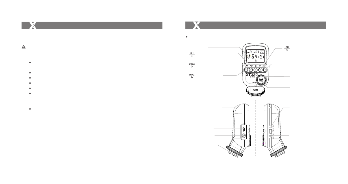
Body
LCD Panel
Channel/
Sleep Setting Button
Sound/
Delay Setting Button
Modeling Lamp/
Lock Setting Button
Status Indicator Lamp
--LED Red Color Lamp
Battery Compartment
Micro USB Port
PC Sync Socket
Hot Shoe
Camera Connection
- 18 -
Group/
PC Sync Socket
Setting Button
TEST Trigger Button
Select Dial
SET Button
AF Assist Beam Switch
--ON (AF Assist
Beam outputs)
--OFF (AF Assist
Beam do not output)
Power Switch
--ON (Power On)
--OFF (Power Off)
Page 5
Names of Parts
A
E
B
F G H
B
C
I
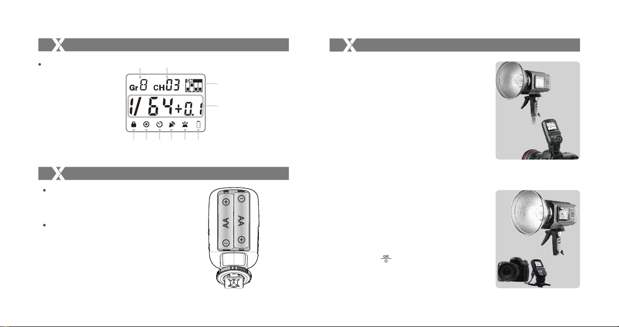
LCD Panel
D
(A)Group (B)Channel (C)Output Level (D)Lock Icon (E)PC Output Icon
(F)Delay Icon (G)Sound Icon (H)Modeling Lamp Icon (I)Low Battery Indicator
Battery
Installing Batteries
As shown in the illustration, slide the battery
compartment lid of the transmitter and
receiver and insert two AA batteries separately.
Low Battery Level Indication
When the battery power (2 AA batteries <2.4V)
gets low, Status Indicator Lamp blinks quickly
(blink cycle=0.5s). Please replace new batteries,
as low power leads to no flash or flash missing
in case of long distance.
- 19 -
Using the Flash Trigger
1. As a Wireless Flash Trigger through Hot Shoe
1.1 Mount the transmitter on camera hotshoe and
turn it on before turning on the camera.
1.2 Set the transmitter and the receiver to the same
channel by pressing Channel Setting Button.
1.3 Press the camera shutter button, and the flash
wi ll b e t rigge re d s imu lt aneou sl y. Stat us
Indicator Lamp of transmitter turns red.
2. As a Wireless Flash Trigger with PC Sync
Socket
2.1 Set the transmitter end and receiver end to the
same channel and group.
2.2 The transmitter will control the flash on the
receiver end to fire via using PC Sync Socket
as input by default.
2.3 Press the camera shutter and use the PC Sync
Socket’s signal to control the flash.
2.4 PC Sync Socket can also be set as output. Long
press the < > Button over 2 seconds until
the settings screen is displayed on the panel.
Then, set the PC Sync Socket as output mode
and “OU” is displayed.
- 20 -
Page 6
Setting the Transmitter
Setting the Transmitter
Power Switch
Slide the Power Switch to ON, and the device is
on and Status Indicator Lamp will not blink. When
in idle use, the flash trigger will enter sleep mode
after a period of time (set as 1 minute/3 minutes/
10 minutes/30 minutes). Press any button or half
press the camera can wake it up.
Setting the sleeping time: Long press the < >
Button over 2 seconds until the settings screen is
displayed on the panel. Turn the Select Dial to
choose the sleeping time.
Note: In order to avoid power consumption, turn
off the transmitter when not in use.
Power Switch of AF Assist Beam
Slide the power switch to ON, and the AF lighting
is allowed to output. When the camera cannot
focus, the AF assist beam will turn on; when the
camera can focus, the AF assist beam will turn off.
- 21 -
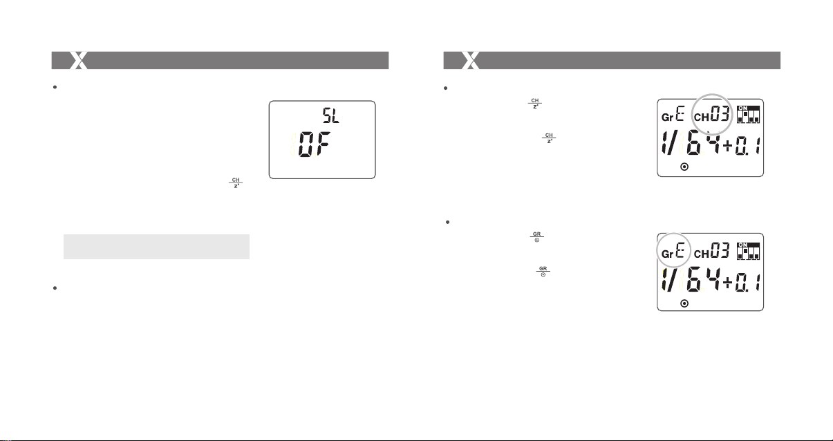
Channel Setting
1. Short press the < > Button until the channel
amount blinks.
2. Turn the Select Dial to choose the appropriate
channel. Press the < > Button again to
confirm the setting.
3. This flash trigger contains 32 channels which can
be changed from 1 to 32. Set the transmitter and
the receiver to the same channel before usage.
Group Settings
1. Short press the < > Button and the selected
group will blink.
2. Turn the Select Dial to choose the appropriate
group. Press the < > Button again to confirm
the setting.
3. This flash trigger contains 16 groups which can
be changed from 0 to 9 and A to F. Set the
transmitter and the receiver to the same group
before usage.
- 22 -
Page 7
Setting the Transmitter
Setting the Transmitter
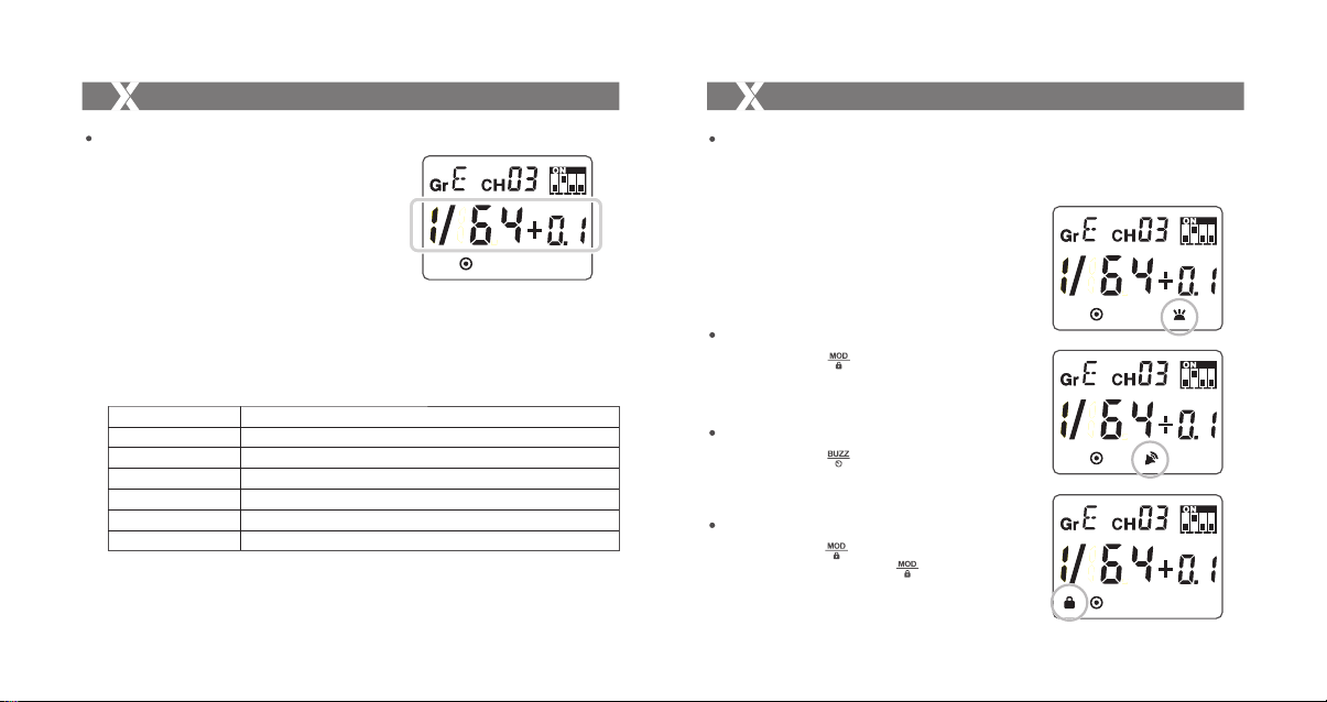
Power Output Settings
1. Turn the Select Dial to adjust the power output
level.
*As XT32C can control so many flashes and
each flash has different power output level,
there are 6 modes to be displayed. Choose
one according to your needs.
Long press the <SET> Button over 2 seconds
until the power output level is displayed. Turn
the Select Dial to choose the power output
mode.
Display
1/128+0.3(by default)
1/128+0.1
1/256+0.3
1/256+0.1
1.0
5.0
Description
Power output range: 1/128~1/1; Power output adjustment: 1/3
Power output range: 1/128~1/1; Power output adjustment: 1/10
Power output range: 1/256~1/1; Power output adjustment: 1/3
Power output range: 1/256~1/1; Power output adjustment: 1/10
Power output range: 1.0~7.0; Power output adjustment: 0.1
Power output range: 5.0~10; Power output adjustment: 0.1
- 23 -
Test Flash
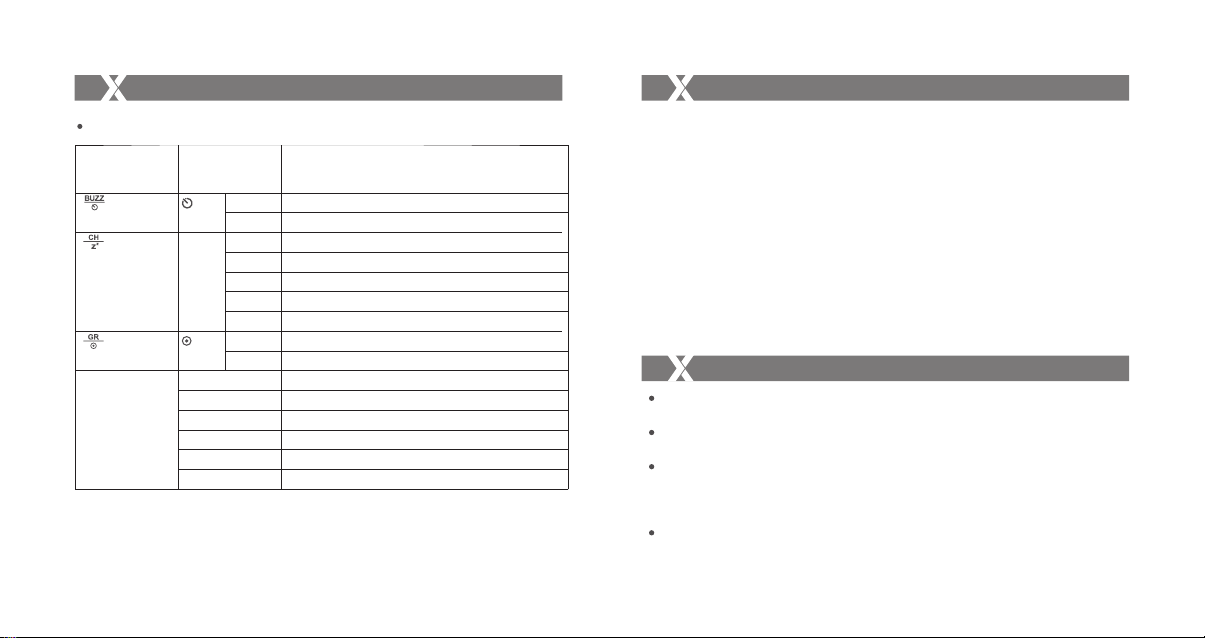
1. Press the <TEST> Trigger Button to see the
whether flash will fire normally or not.
2. Fully press the <TEST> Trigger Button, and
the Status Indicator Lamp turns red and the
flash on the receive end can be triggered.
3. The settings on the transmitter end will
synchronize to the receiver end at the same
time.
Modeling Flash Control
Short press the < > Button can control the
ON/OFF of modeling lamp.
Sound Control
Short press the < > Button can control the
ON/OFF of sound.
Lock Functions
Long press the < > Button can lock the current
settings and long press the < > again to unlock.
- 24 -
Page 8
Setting the Transmitter
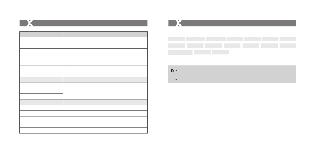
Setting Custom Functions
Operation
(Long press the button
over 2 seconds)
< >
< >
< >
<SET>
Display
00
1~100
SL
01
03
10
30
OF
IN
OU
1/128+0.3 (by default)
1/128+0.1
1/256+0.3
1/256+0.1
1.0
5.0
Settings and Description
OFF
Synchronization delay N*100 us
Enter sleep mode after 1 minute of idle use
Enter sleep mode after 3 minutes of idle use
Enter sleep mode after 10 minutes of idle use
Enter sleep mode after 30 minutes of idle use
Do not enter sleep mode
PC Sync socket connect with camera
PC sync socket connects with flash
Power output range: 1/128~1/1; Power output adjustment: 1/3
Power output range: 1/128~1/1; Power output adjustment: 1/10
Power output range: 1/256~1/1; Power output adjustment: 1/3
Power output range: 1/256~1/1; Power output adjustment: 1/10
Power output range: 1.0~7.0; Power output adjustment: 0.1
Power output range: 5.0~10; Power output adjustment: 0.1
- 25 -
Attentions
1. Unable to trigger flash or camera shutter. Make sure batteries are installed correctly and
Power Switch is turned on. Check if the transmitter and the receiver are set to the same
channel, if the hotshoe mount or connection cable is well connected, or if the flash
triggers are set to the correct mode.
2. Camera shoots but does not focus. Check if the focus mode of the camera or lens is set
to MF. If so, set it to AF.
3. Signal disturbance or shooting interference. Change a different channel on the device.
4. Operating distance limited or flash missing. Check if batteries are exhausted. If so,
change them.
Maintenance
Avoid sudden drops. The device may fail to work after strong shocks, impacts, or
excess stress.
Keep dry. The product isn’t water-proof. Malfunction, rust, and corrosion may occur and
go beyond repair if soaked in water or exposed to high humidity.
Avoid sudden temperature changes. Condensation happens if sudden temperature
changes such as the circumstance when taking the transceiver out of a building with
higher temperature to outside in winter. Please put the transceiver in a handbag or
plastic bag beforehand.
Keep away from strong magnetic field. The strong static or magnetic field produced
by devices such as radio transmitters leads to malfunction.
- 26 -
Page 9
Technical Data
Compatible Camera Models
Model
Compatible Cameras
Built-in remote system
Modulation mode
Power supply
High-speed sync
Focus assist
Second curtain sync
Transmission range(approx.)
Channel
Group
Synchronization delay set
Modeling lamp
Sound
Memory function
Dimension/Weight
XT32C
Canon cameras
Support for the cameras that have PC sync socket.
2.4G Wireless transmission
MSK
2*AA batteries
Yes (1/8000s)
Manual open
Yes (Setting on the camera)
>100m
32
16 (0~9; A~F)
Yes (0~10ms, use 100us as the unit)
ON/OFF
ON/OFF
Settings will be stored for 2 seconds after last operation and
recover after a restart
100x50x52mm/80g
- 27 -
This flash trigger can be used on the following Canon EOS series camera models:
5D Mark III 5D Mark II
1DX
40D 30D
400D Digital
This table only lists the tested camera models, not all Canon EOS series cameras.
For the compatibility of other camera models, a self-test is recommended.
Rights to modify this table are retained.
650D 600D
1000D 1100D
- 28 -
6D
7D
550D 500D 450D
60D
50D
 Loading...