

Page 1
Wireless Power-Control Flash TriggerWireless Power-Control Flash Trigger
Cheetah Light LLC.
www.cheetahstand.com
info@cheetahstand.com
(214)734-1198
CL-Tx CL-Rx
Instruction manual
Page 2

Foreword
Thank you for purchasing this Cheetah product.
The wireless power-control flash trigger CL-Tx,CL-Rx is
designed for versatile use. When used on Cheetah Light
(with wireless control port) it is not only a flash trigger but also
incorporates multiple functions such as adjusting power ratio,
and controlling the on-or-off of the buzzer or the AF-assist
beam. The trigger set consists of a transmitter (on-camera) and
a receiver (on-flash).
Contents
Foreword
For your safety
Parts
●Body
●Battery
●ON/OFF Switch
●Power-Ratio Display Mode
●Channel Select Switch
●Power-Control Group Selection
●Other Buttons
Using the Trigger
●Adjusting Flash Settings
●Triggering Flash
Technical Data
Troubleshooting
Maintenance
For your safety
Before using this product, please read the following safety
instructions carefully in order to ensure your safety and the
proper operation of this product. Keep for future reference.
Failure to observe the following precautions marked by
could result in product damages. The icon indicates
warnings that should be read beforehand to avoid any possible
damage or injury.
Do not disassemble or modify.
Failure to observe this precaution could result in electric shock
or product malfunction. Should this product break open due to
falling or other accident, take out the batteries and sent it to an
authorized maintenance center.
Keep dry.
Do not handle with wet hands, immerse in water, or expose to
rain. Failure to observe this precaution could cause fire or
electric shock.
Do not use in the presence of flammable gases.
Failure to observe this precaution could result in fire or
explosion.
Keep out of the reach of children.
This product contains small parts that may pose a choking
hazard. Should a child swallows any part of this product,
consult a physician immediately.
Turn off the trigger immediately should malfunction
occurs.
Should smoke or an unusual smell come from this product,
take out the batteries immediately in case of burning and send
this product to an authorized maintenance center. Continued
use may result in injuries.
Page 3

Do not expose to high temperature. damage to the product, be sure to take out the batteries if the
Do not leave the product in a closed vehicle in the sun or in
other areas subject to extremely high temperature. Failure to
observe this precaution could result in fire or damage to the Should liquid from damaged batteries come into contact with
casing or internal parts. skin or clothing, rinse immediately with fresh water.
Observe precautions when handling batteries.
Batteries may leak or explode if improperly handled. Please
observe the following precautions when handling batteries for
this product:
Use only batteries listed in this manual. Do not mix new and old
batteries. Neither use batteries of different brands.
Read and follow all warnings and instructions provided by the
battery manufacturer.
Do not put batteries into a fire or apply direct heat to them.
Do not attempt to install batteries in the reverse direction.
Batteries are prone to leak when fully discharged. To avoid
product will not be used for an extended period or the battery
power is empty.
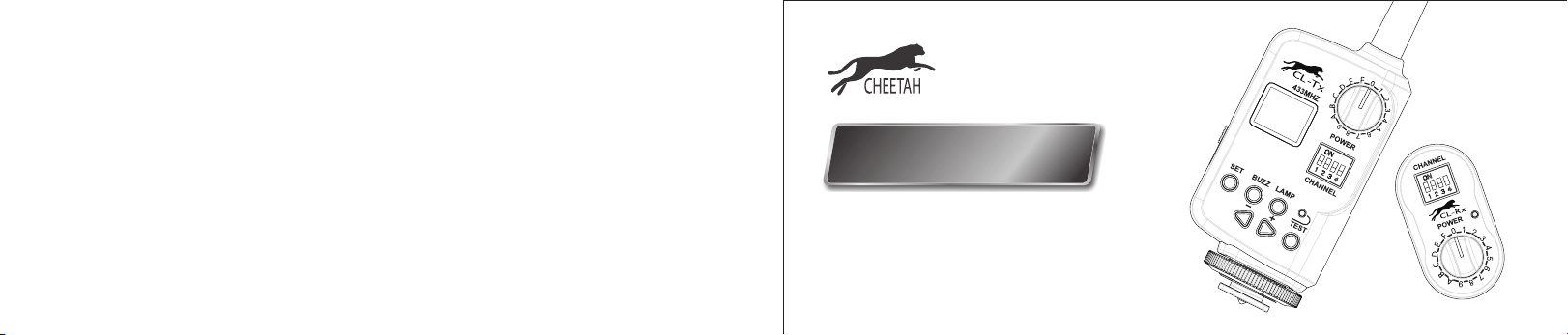
Parts
Body
01. ON/OFF Switch
Power on (ON)
Power off (OFF)
02. LCD display
03. Power-Control Group Select Dial (POWER)
04. Channel Select Switch (CHANNEL)
05. Set Button (SET)
06. Buzz Switch (BUZZ)
07. AF-assist Beam Switch (LAMP)
08. Test Button (TEST)
09. <-> Button
10. <+> Button
11. Hot shoe
12. Indicator
13. Antenna
14. Battery Compartment
15. Wireless Control Plug
Transmitter CL-Tx
14
02
01
05
09
16
11
13
03
04
06
12
07
08
10
15
12
03
Receiver CL-Rx
Page 4

Battery
The transmitter requires two size-AA batteries (not provided).
The receiver draws power from the flash through the flash’s
Wireless Control Port. Slide the battery compartment cover of
the transmitter and insert the batteries.
Low Battery Indication
When the battery power (<2.2V) gets low, is shown on the
LCD display. Please change batteries.
Power Switch
Turn the transmitter on by sliding the ON/OFF Switch to ON. The
LCD display will then light up.
Turn the transmitter off to save power if it will not be used for
an extended period.
Power-Ratio Display Mode
The trigger set has two modes to display a flash’s power ratio.
1. 1/128~1/1: widely adopted in most shoe mount flashes.
2. 5.0~10: widely adopted in most studio flashes.
The two display modes can be switched over by pressing the Set
Button and holding for 2s.
Channel Select Switch
The trigger set provides 16 channels for communication. Set the
transmitter and the receiver to the same channel before use.
Check the following table for channel settings:
Channel
1
2
3
4
5
6
7
S1
0
1
0
1
0
1
0
S2
0
0
1
1
0
0
1
S3
0
0
0
0
1
1
1
S4
0
0
0
0
0
0
0
Channel
9
10
11
12
13
14
15
S1
0
1
0
1
0
1
0
S2
0
0
1
1
0
0
1
S3
0
0
0
0
1
1
1
S4
1
1
1
1
1
1
1
The transmitter and the receiver must be set to the same
channel for wireless control, or the receiver will not respond.
8
1
1
1
0
Power-Control Group Selection
Both the transmitter and the receiver have a 16-grade PowerControl Group Select Dial (hereinafter referred to as Dial). With
these 16 grades, you can wirelessly control up to 16 flash
groups in terms of the following functions: adjusting the power
ratios and turning on/off the buzzer and the AF-assist beam, as
16
well as flash triggering.
1
Attach the receiver(s) on multiple flashes/one flash and set the
1
dial of each receiver to the same grade. This is a flash group.
1
Then attach the transmitter on the camera's hotshoe or hold it
1
in hand, and set the Dial to the same grade as that of
receiver(s). The flashes will be under your command.
1. The Dial of the transmitter and the receiver must be set to
the same grade. Otherwise, the receiver will not respond.
2. Flash triggering is only related to the Channel Select
Switch. The Power-Control Group Select Dial only decides
which flash or flash group to be controlled in terms of
functions such as power setting.
Page 5

Other Buttons power ratio. “OF, 1/128~1/1” for Cheetah Light. “OF” means
1. Set Button (SET)
Press the Set button and settings on the transmitter will be
communicated with the flash through the receiver. Will Press Test Button to fire the flash. Both the indicators on the
blink for a second. on the LCD display. transmitter and the receiver will blink.
Press and hold the Set button for 2 sec. to switch the powerratio display mode.
2. Buzz Switch (BUZZ)
Press the Buzz Switch to turn the buzzer on or off. When the
buzzer is turned on, will be shown on the LCD display.
3. AF-Assist Beam Switch (LAMP)
Press the switch to turn the AF-assist beam on or off. When
the beam is turned on, will be shown on the LCD
display.
4. <-><+> Button
Press the <-> or <+> button to decrease or increase the
the flash triggering function is shut down on the flash.
5. Test Button (TEST)
Using the Trigger Set
■ Wireless Adjusting Flash Settings
The trigger set can wirelessly adjust the following settings: the
flash power ratio, the on-or-off of the buzzer and the AF-assist
beam, as well as the power-ratio display mode.
1. On the transmitter and the receiver, set the Channel Select
Switch to the same position and the Power-Control Group
Select Dial to the same grade.
2. Insert the receiver into the Wireless Control Port of the flash
unit. Then power the flash on.
3. Adjust the flash settings on your transmitter.
■ Wireless Triggering
1. On the transmitter and the receiver, set the Channel Select
Switch to the same position.
2. Insert the receiver into the Wireless Control Port of the flash
unit. Then power the flash on.
3. Press the Test Button to fire a flash. Alternatively, you can
set the transmitter onto the camera's hot shoe and press the
camera's shutter-release button to fire a flash.
Technical Data
Transmitter Power Supply
Receiver Power Supply
Transmit Frequency
Workable Distance
Control on Flashes
Max. Sync. Speed
Channel
Net Weight
Transmitter Dimension (L x W x H)
Receiver Dimension (L x W x H)
3V (2*AA Ni-MH or alkaline batteries )
5V (powered by flashes)
433MHz wireless remote system
300ft (open areas)
Flash power ratio
AF-assist beam on/off
Buzzer on/off
Power-ratio display mode
Flash triggering
1/250 second
16
85g for the set
20g for the receiver
97.6*49.9*36.95mm
57*30*26.5mm
Page 6

Troubleshooting Maintenance.
1. Unable to trigger a flash by pressing Test Button or the
camera's shutter-release button.
Make sure batteries are installed properly and the trigger set
is powered on.
Check if the transmitter and the receiver are set to the same
channel. If not, set to the same position.
Check if the trigger set is securely seated into the camera's
hot shoe.
2. Signal disturbance or shooting interference.
Change a different channel on the trigger set.
1. Avoid sudden drops. The device may malfunction after
strong shocks or impacts.
2. Keep dry. The device is not water-proof. Malfunction, rust,
and corrosion may occur and the device may go beyond
repair if immersed in water or expose to high humidity.
3. Keep away from strong magnetic field. The strong static
or magnetic field produced by devices such as ratio
transmitters leads to malfunction.
 Loading...