

Page 1
CHEETAH Hardware User’s Manual
CHEETAH C5180, C4181, C4180 and C3880 Hardware
User’s Manual
HIGH-SPEED, HIGH-RESOLUTION, AND VERSATILE CMOS DIGITAL
CAMERAS
CONFIDENTIAL NOTICE:
These products are not intended for use in life support appliances, devices, or systems where malfunction of these
products can reasonably be expected to result in personal injury. Imperx customers using or selling these products for
use in such applications do so at their own risk and agree to fully indemnify Imperx for any damages resulting from
such improper use or sale.
Copyright © 2011, Imperx Inc. All rights reserved. All information provided in this manual is believed to be accurate
and reliable. Imperx assumes no responsibility for its use. Imperx reserves the right to make changes to this information
without notice. Redistribution of this manual in whole or in part, by any means, is prohibited without obtaining prior
permission from Imperx.
Imperx, Inc. Rev. 1.6
6421 Congress Ave. 8/26/2016
Boca Raton, FL 33487
+1 (561) 989-0006 1 of 121
Page 2

Revision History
Rev 1.0
10/30/15
K. Wetzel
Initial Pre-Release l
Rev 1.1
4/7/16
K. Wetzel
Added Register and GUI info. Input from Gennady
Rev 1.2
4/20/16
K. Wetzel
Updated CamConfig registers and C3880 framerates
Rev 1.3
5/4/16
K. Wetzel
Updated minimum ROI width to 320
Rev 1.4
5/25/16
K. Wetzel
Update Figure 51 description, removed single tap mode
from Figures 15, 16 and 17. Zero ROT not supported in
Averaging mode.
Rev 1.5
6/7/16
K. Wetzel
Updated PG period and width in Section 2.9
Rev 1.6
7/22/16
K. Wetzel
Updated Mechanical Drawings in 1.6.4, Cheetah images
and Appendix E Power Supply Schematic
Rev 1.7
8/19/2016
M.Pangburn
Adjusted Graph/Data and TOC
Rev 1.8
8/19/16
E. Fateyeva
Adjusted Graph/Data, updated logo in header, replaced
pyramid image with Cheetah sketch image
CHEETAH Hardware User’s Manual
Imperx, Inc. Rev 1.7
6421 Congress Ave. 8/26/2016
Boca Raton, FL 33487
+1 (561) 989-0006 2 of 121
Page 3

CHEETAH Hardware User’s Manual
TABLE OF CONTENTS
Contents
CHAPTER 1 – INTRODUCTION 10
1.0 CHEETAH FAMILY 11
1.1 GENERAL DESCRIPTION 11
1.2 MAIN CHEETAH FEATURES 13
1.3 CHEETAH SPECIFICATIONS 13
1.3.1 General Information 13
1.3.2 Spectral Sensitivity Curves 16
1.3.3 Bayer Pattern Information 17
1.4 TECHNICAL SPECIFICATIONS 17
1.5 CAMERA CONNECTIVITY 19
1.5.1 CLF (Full) - Camera Link (CL) Output 19
1.5.2 Camera Link Full Signal Mapping 20
1.5.3 Camera Link Physical Layer to Camera Link Receiver Bits 22
1.5.4 Camera Link Bit to Port Bit assignments 23
1.5.5 Camera Link Port assignments based on selected output configuration 27
1.5.6 Camera Power Connector 28
1.6 MECHANICAL, OPTICAL, and ENVIRONMENTAL 29
1.6.1 Mechanical 29
1.6.2 Optical 29
1.6.3 Environmental 30
1.6.4 Mechanical Drawings 31
CHAPTER 2 – CAMERA FEATURES 32
2.1.1 Internal Exposure Control - Electronic Shutter 33
2.1.2 External exposure control 33
2.2 FRAME TIME CONTROL 34
2.2.1 Internal Line and Frame Time Control 34
2.2.2 Camera Output Control 35
2.3 AREA OF INTEREST 36
2.3.1 Overview 36
Imperx, Inc. Rev 1.7
6421 Congress Ave. 8/26/2016
Boca Raton, FL 33487
+1 (561) 989-0006 3 of 121
Page 4

CHEETAH Hardware User’s Manual
2.3.2 Horizontal and Vertical Window 36
2.3.3 Factors Impacting Frame Rate 37
2.4 SUBSAMPLING 39
2.4.1 Pixel Averaging 39
2.4.2 Sub-sampling Decimation 40
2.5 CAMERA TRIGGERING 41
2.5.1 Triggering Inputs 41
2.5.2 Acquisition and Exposure Control 41
2.5.3 Triggering modes 42
2.6 STROBES 43
2.7 VIDEO AMPLIFIER GAIN AND OFFSET 43
2.7.1 Analog Gain 43
2.7.2 Digital Gain 44
2.7.3 Digital Offset 44
2.7.4 Black Level Auto-calibration and Black Level Offset 44
2.8 DATA OUTPUT FORMAT 44
2.8.1 Bit Depth 44
2.8.2 Output Taps 45
2.9 PULSE GENERATOR 45
2.10 I/O CONTROL 46
2.10.1 Input / Output Mapping 46
2.10.2 Electrical Connectivity 46
2.11 TEST IMAGE PATTERNS 48
2.11.1Test Image patterns 48
2.12 WHITE BALANCE AND COLOR CONVERSION 49
2.12.1 White Balance Correction 49
2.13 TRANSFER FUNCTION CORRECTION – USER LUT 49
2.13.1 Standard Gamma Correction 50
2.13.2 User Defined LUT 51
2.14 DEFECTIVE PIXEL CORRECTION 52
2.14.1 Static Pixel Correction 52
2.14.2 Dynamic Pixel Correction 53
2.15 FLAT FIELD AND FPN CORRECTION 53
Imperx, Inc. Rev 1.7
6421 Congress Ave. 8/26/2016
Boca Raton, FL 33487
+1 (561) 989-0006 4 of 121
Page 5

CHEETAH Hardware User’s Manual
2.16 CAMERA INTERFACE 53
2.16.1 Status LED 53
2.16.2 Temperature Monitor 53
2.16.3 Exposure Time Monitor 54
2.16.4 Frame Time Monitor 54
2.16.5 Current image size 54
HAPTER 3 – CAMERA CONFIGURATION 55
3.1 Overview 56
3.2 CAMERA CONFIGURATION 56
3.2.1 Configuration Memory – parameter FLASH 56
3.3 CAMERA CONFIGURATION REGISTER DESCRIPTION 60
3.3.1 Startup Procedure 60
3.3.2 Saving and Restoring Settings 60
3.3.3 Retrieving Manufacturing Data 62
3.3.4 Camera Information Registers 64
3.3.5 Frame Exposure Control 66
3.3.6 Exposure Time (Internal) 66
3.3.7 Programmable Frame Period Enable 67
3.3.8 Output Pixel Clock Rate and Zero ROT 67
3.3.9 Fixed Frame Period 67
3.3.10 Area of Interest 68
3.3.11 Decimation (Averaging or Subsampling) 68
3.3.12 Black Level auto-calibration 69
3.3.13 Analog and Digital Gain 69
3.3.14 Triggering Workspace Registers 70
3.3.15 Strobe Control Registers 72
3.3.16 Pulse Generator Registers 73
3.3.17 Test Pattern Workspace Registers 74
3.3.18 Input/output Workspace Registers 75
3.3.19 Data Output Bit Depth/Format Selector 76
3.3.20 White Balance (WB) Workspace Registers 76
3.3.21 Data Correction Workspace Registers 78
3.3.22 Flat Field Correction and FPN Correction 79
CHAPTER 4 - CONFIGURATOR FOR CAMERALINK 80
4.1 OVERVIEW 81
4.2 DISCOVERY PROCEDURE 81
Imperx, Inc. Rev 1.7
6421 Congress Ave. 8/26/2016
Boca Raton, FL 33487
+1 (561) 989-0006 5 of 121
Page 6

CHEETAH Hardware User’s Manual
4.3 GRAPHICAL USER INTERFACE 82
4.4 MAIN GUI MENU 83
4.5 VIEW GUI WINDOWS 86
4.6 MENU HELP 87
4.7 PARAMETER WINDOWS 88
4.7.1 Acquisition Control Panel 89
4.7.2 Trigger Panel 93
4.7.3 Pulse Generator Panel 94
4.7.4 Strobe Control and Output Mapping 95
4.7.5 Data Output Panel 97
4.7.6 Color 100
CHAPTER 5 CHEETAH WARRANTY AND SUPPORT 101
5.1 ORDERING INFORMATION 102
5.2 TECHNICAL SUPPORT 102
5.3 WARRANTY 103
APPENDIX A – CAMERA CONFIGURATION REFERENCE 104
A.0 ABBREVIATIONS 105
A.1 SAVING AND RESTORING REGISTERS 105
A.2 CAMERA INFORMATION REGISTERS 105
A.3 ACQUISITION REGISTERS (Stored in FLASH) 106
A.4 TRIGGER REGISTERS 107
A.5 PULSE GENERATOR REGISTERS 107
A.6 TEST PATTERN REGISTERS 107
A.7 STROBE REGISTERS 108
A.8 INPUT AND OUTPUT REGISTERS 108
A.9 OUTPUT DATA FORMAT REGISTERS 108
Imperx, Inc. Rev 1.7
6421 Congress Ave. 8/26/2016
Boca Raton, FL 33487
+1 (561) 989-0006 6 of 121
Page 7

CHEETAH Hardware User’s Manual
A.10 WB AND COLOR CORRECTION REGISTERS 109
A.11 DATA CORRECTION REGISTERS 109
A.12 MANUFACTURING DATA REGISTERS 110
APPENDIX B – CREATING LOOK UP TABLES 111
B.1 OVERVIEW 112
B.2 USING AN ASCII TEXT EDITOR 112
B.3 USING MICROSOFT EXCEL 113
APPENDIX C – CREATING DPC AND HPC TABLES 114
C.1 OVERVIEW 115
C.2 USING AN ASCII TEXT EDITOR 115
APPENDIX D – SOFTWARE INSTALLATION - CL 116
APPENDIX E – POWER SUPPLIES 118
INDEX OF TABLES
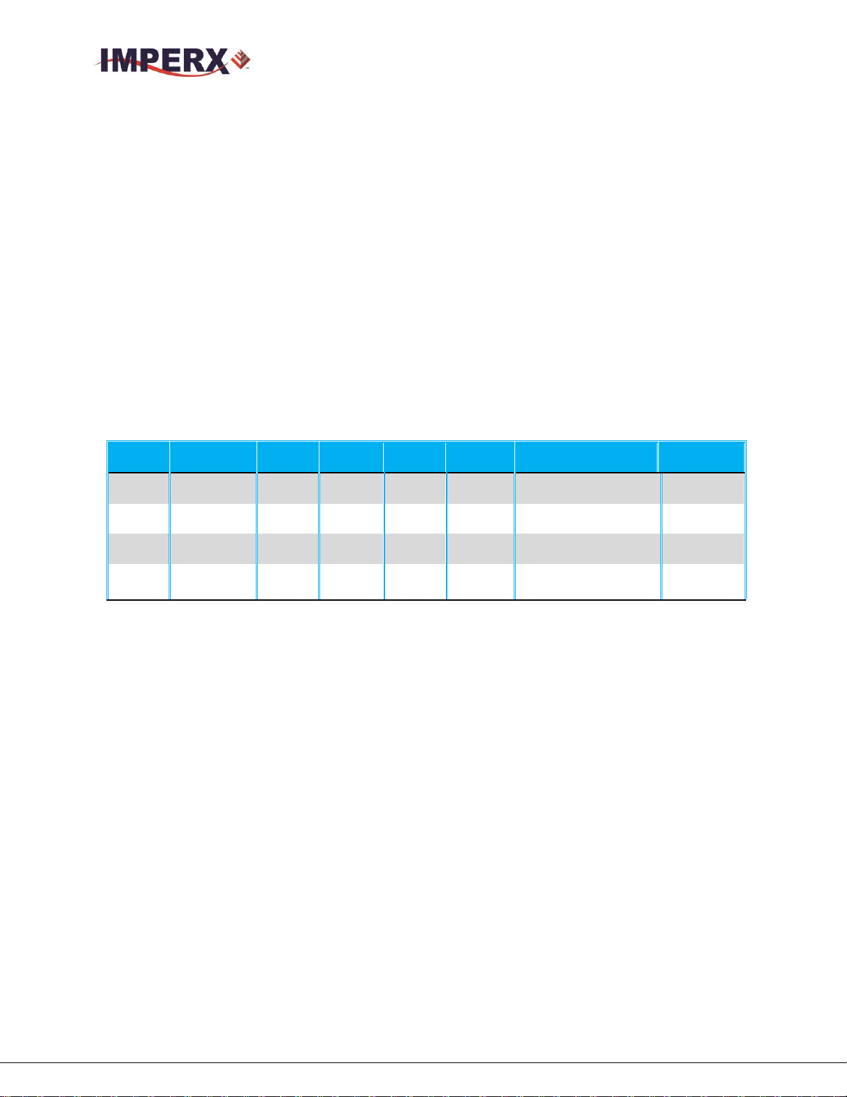
Table 1: Cheetah C5180, C4181, C4180 and C3880 Overview 11
Table 2: Cheetah General Features List 17
Table 3: Cheetah C5180, C4181, C4180, C3880 Specifications 19
Table 4: CLF Camera Output Connector 1 – Signal Mapping 21
Table 5: CLF Camera Output Connector 2 – Signal Mapping 22
Table 6: Camera Link Connector #1 (X0-X3) 24
Table 7: Camera Link Connector #2 (Y0-Y3) 25
Table 8: Camera Link Connector #2 (Z0-Z3) 26
Table 9: Image data bit-to-port assignments– Base modes 27
Table 10: Image data bit-to-port assignments– Medium modes 27
Table 11: Image data bit-to-port assignments– Full mode 27
Table 12: Image data bit-to-port assignments– Deca modes 28
Table 13: Camera Power Connector Pin Mapping 29
Table 14: C5180 frame rates vs output taps 35
Imperx, Inc. Rev 1.7
6421 Congress Ave. 8/26/2016
Boca Raton, FL 33487
+1 (561) 989-0006 7 of 121
Page 8

CHEETAH Hardware User’s Manual
Table 15: C4181 frame rates vs output taps 35
Table 16: C4180 frame rates vs output taps 36
Table 17: C3880 frame rates vs output taps 36
Table 18: C5180 AOI frame rate for various AOIs 38
Table 19: C3880 Maximum Frame Rate for various AOIs 39
Table 20: CHEETAH Output Mapping 46
Table 21: Current camera temperature values 66
Table 22: Cheetah Part Numbers 102
INDEX OF FIGURES
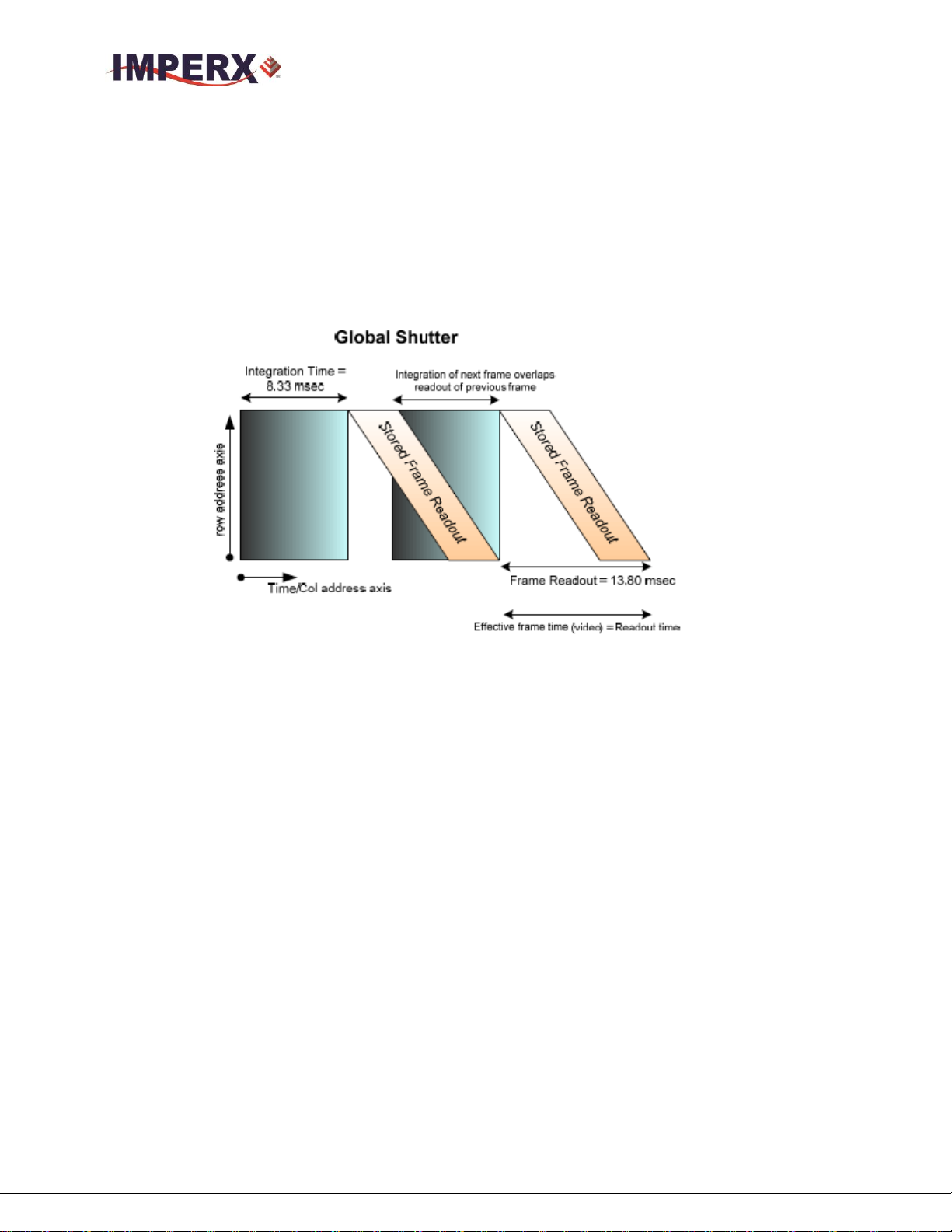
Figure 1: Global Shutter Description 14
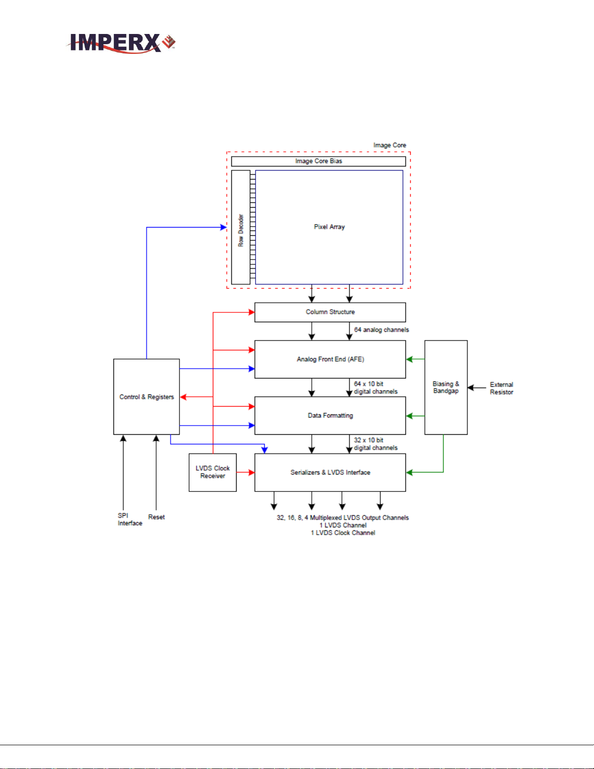
Figure 2: CMOS image sensor architecture 15
Figure 3: Python CMOS mono spectral response 16
Figure 4: Python CMOS typical color spectral response 16
Figure 5: CLF Camera back panel / Deca, Full, Medium or Base 20
Figure 6: CLF Camera output connector 1 20
Figure 7: CLF Camera output connector 2 21
Figure 8: Camera Link bit sequence over the physical connection 23
Figure 9: Camera Power Connector (Viewed from rear) 28
Figure 10: C5180, C4181, C4180 and C3880 Mechanical Drawings 31
Figure 11: Global Shutter with 8.33mS exposure time 33
Figure 12: Horizontal and vertical window positioning 37
Figure 13: Monochrome pixel averaging 39
Figure 14: Monochrome sub-sampling 40
Figure 15: Color sub-sampling 40
Figure 16: Trigger Mode (Internal Exposure Control) 42
Figure 17: Trigger Mode (Pulse Width Exposure Control) 43
Figure 18: Strobe positioning with respect to exposure start 43
Figure 19: 10-bit internal Digitization with 8 and 10-bit outputs 45
Figure 20: Internal pulse generator 46
Figure 21: IN1 electrical connection 47
Figure 22: IN 2 electrical connection 47
Figure 23: OUT 1 LVTTL electrical connection 48
Figure 24: OUT 2 Opto-Isolated electrical connection 48
Figure 25: Look up table 50
Figure 26: Gamma corrected video signal 51
Figure 27: Custom LUT 51
Imperx, Inc. Rev 1.7
6421 Congress Ave. 8/26/2016
Boca Raton, FL 33487
+1 (561) 989-0006 8 of 121
Page 9

CHEETAH Hardware User’s Manual
Figure 28: Serial protocol format 57
Figure 29: Normal write cycle 58
Figure 30: Invalid command error 58
Figure 31: Rx timeout error 58
Figure 32: Normal read cycle 59
Figure 33: Discovery procedure – select port 81
Figure 34: CamConfig GUI 82
Figure 35: Main Menu 83
Figure 36: Defective pixel map 84
Figure 37: Command terminal 85
Figure 38: View Menu 86
Figure 39: Help menu 87
Figure 40: About CamConfig 88
Figure 41: Acquisition Control Panel 89
Figure 42: Exposure control window 90
Figure 43: AOI Functions 91
Figure 44: Subsampling Functions 91
Figure 45: Video Amp parameter Menu 92
Figure 46: Trigger parameter Menu 93
Figure 47: Pulse Generator Panel 94
Figure 48: Strobe Control Panel 96
Figure 49: Data Output Panel 97
Figure 50: DPC and HPC options 98
Figure 51: Color Panel 100
Figure 52: Model: PS12V04 standard power supply ordered separately 119
Figure 53: Trigger & Strobe pigtail with Male BNC connectors 119
Figure 54: Power Supply Connection Diagram 120
Figure 55: Power Supply Specifications 121
Imperx, Inc. Rev 1.7
6421 Congress Ave. 8/26/2016
Boca Raton, FL 33487
+1 (561) 989-0006 9 of 121
Page 10

CHEETAH Hardware User’s Manual
Chapter 1 – Introduction
Introduction
This chapter outlines the key features of the CHEETAH C5180, C4181,
C4180 and C3880 cameras.
Imperx, Inc. Rev 1.7
6421 Congress Ave. 8/26/2016
Boca Raton, FL 33487
+1 (561) 989-0006 10 of 121
Page 11
CHEETAH Hardware User’s Manual
Model
Resolution
(H x V)
Speed
(fps)
Type
Optics
CMOS
Sensor
Supported
Outputs
C5180M
5120 x 5120
32
Mono
35mm
ONSEMI
NOIP1SN025KA
CLF/CXP*
C5180C
5120 x 5120
32
Color
35mm
ONSEMI
NOIP1SN025KA
CLF/CXP*
C4181M
4096 x 4096
50
Mono
35mm
ONSEMI
NOIP1SN016KA
CLF/CXP*
C4181C
4096 x 4096
50
Color
35mm
ONSEMI
NOIP1SN016KA
CLF/CXP*
C4180M
4096 x 3072
67
Mono
4/3”
ONSEMI
NOIP1SN012KA
CLF/CXP*
C4180C
4096 x 3072
67
Color
4/3”
ONSEMI
NOIP1SN012KA
CLF/CXP*
C3880M
3840 x 2896
75
Mono
4/3”
ONSEMI
NOIP1SN010KA
CLF/CXP*
C3880C
3840 x 2896
75
Color
4/3”
ONSEMI
NOIP1SN010KA
CLF/CXP*
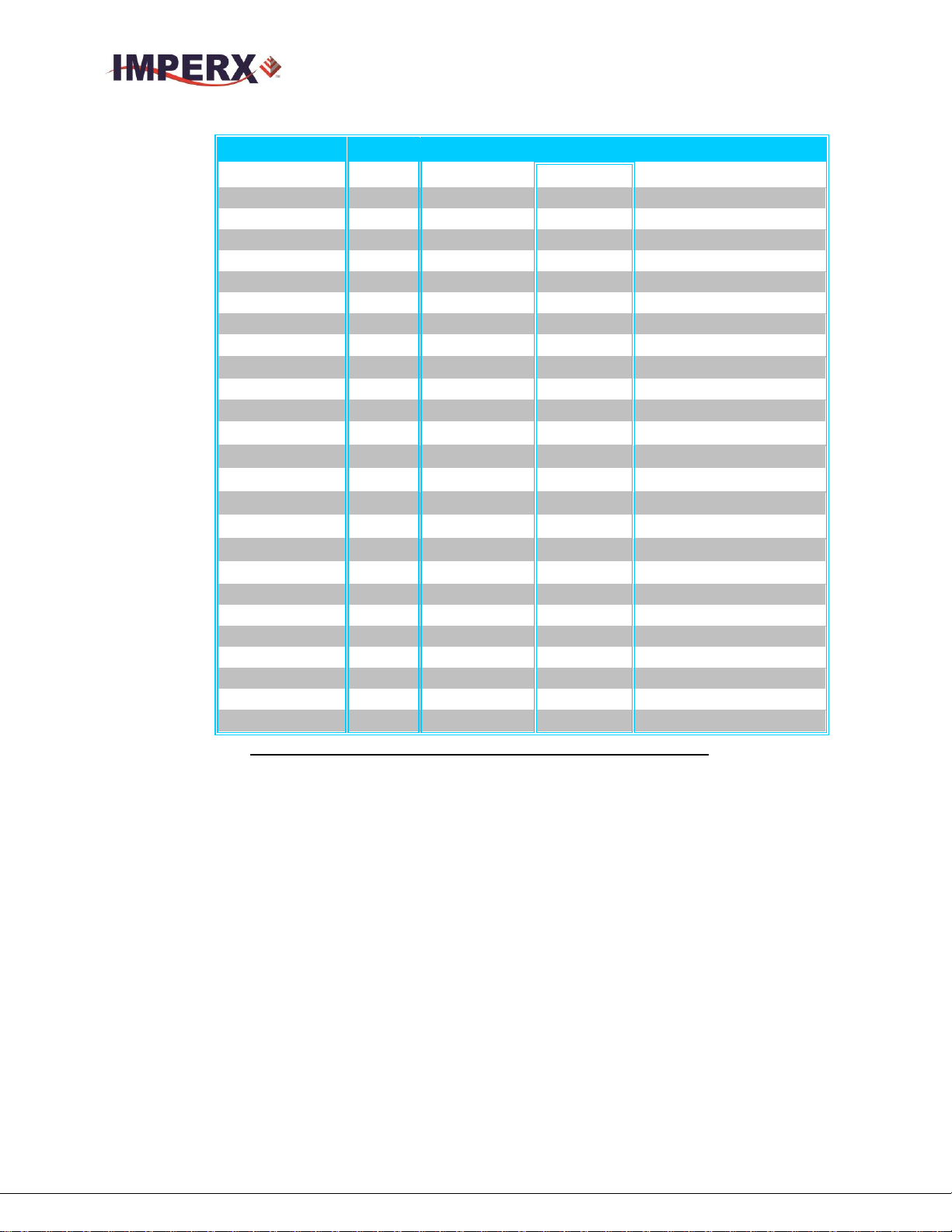
1.0 CHEETAH FAMILY
The CHEETAH series of cameras are built around a robust imaging platform utilizing the latest
digital technology and components with CMOS imaging sensors, featuring different resolutions /
frame rates and available in both monochrome and color. The Cheetah family currently supports
Camera Link output. The CHEETAH series is programmable to support Camera Link Deca, Full,
Camera Link Medium and Camera Link Base depending upon the user’s needs.
This manual describes the C5180, C4181, C4180 and C3880 camera products which are listed
below using the Camera Link Output:
Table 1: Cheetah C5180, C4181, C4180 and C3880 Overview
1.1 GENERAL DESCRIPTION
The CHEETAH cameras are advanced, intelligent, high-resolution, progressive scan, fully
programmable and field upgradeable CMOS cameras. They are built around On
Semiconductors area scan Python CMOS imagers and are feature rich with a built-in image
processing engine, low noise, and efficient and optimized internal thermal distribution. The
CHEETAH cameras feature a wide range of programmable functions; including, , exposure
control, frame rate control, area of interest, subsampling, pixel averaging, gain, offset,
several triggering options, strobes, output control, transfer function correction, temperature
monitoring and user programmable and up-loadable LUT.
All Cheetah cameras offer global shutter for superior motion capture and exceptionally high
frame rates for high thru-put applications. Cheetah camera exposure time can be controlled
using an internal control or controlled by an external pulse width. Exposure times up to 1
second with 1µs increments are supported. An Area of Interest (AOI) can be programmed
for each acquisition frame and subsampling or pixel averaging capabilities are also
Imperx, Inc. Rev 1.7
6421 Congress Ave. 8/26/2016
Boca Raton, FL 33487
+1 (561) 989-0006 11 of 121
Page 12

CHEETAH Hardware User’s Manual
available. Analog gains up to 10 dB (3.17x) are supported and digital gain controls allow
further expansion of the low-end signal with 24dB (16x) of additional gain available.
A built-in Gamma correction and user-defined Look-up Table (LUT) capability optimizes
the camera’s dynamic range even further. Defective pixel Correction (DPC) and hot pixel
correction (HPC) can also be applied to correct for pixels that are over-responding or underresponding. Auto-White Balance (AWB) is available in color cameras to correct for color
temperature. The cameras have a Camera Link™ interface that includes 8/10/12 bits data
transmission with two, four, eight or ten output taps as well as camera control all on one or
two cables. The cameras are fully programmable via the Camera Link interface. The
adaptability and flexibility of the camera allow it to be used in a wide and diverse range of
applications including machine vision, metrology high-definition imaging and surveillance,
medical and scientific imaging, intelligent transportation systems, aerial imaging, character
recognition, document processing and many more.
Imperx, Inc. Rev 1.7
6421 Congress Ave. 8/26/2016
Boca Raton, FL 33487
+1 (561) 989-0006 12 of 121
Page 13

CHEETAH Hardware User’s Manual
1.2 MAIN CHEETAH FEATURES
Global shutter (GS)
Monochrome or color
Large 4.5 micron pixels
Fixed pattern noise (FPN) correction
Enhanced near infrared (NIR) sensitivity version available upon request
Fast frame rates:32 fps (C5180), 50fps (C4181), 67 fps (C4180) and 75 fps (C3880)
Configurable Pixel Clock
Pixel Averaging
Sub-sampling
Area of Interest
Analog and Digital Gain Controls
Offset Control
Three selectable trigger sources: external, pulse generator or computer
Built-in pulse generator
Two programmable output strobes
Auto-white balance: once, static or tracking
Two 12-bit look-up tables (LUT)
Defective pixel correction (DPC), hot pixel correction (HPC)
Two programmable external inputs (one opto-isolated) and two external outputs (one opto-
isolated)
Flat Field Correction (FFC), User and Factory
Camera Link Base, Medium, Full and Deca support
Temperature monitor
Field upgradeable firmware, LUT, DPC, HPC, FFC
1.3 CHEETAH SPECIFICATIONS
1.3.1 General Information
A CMOS camera is an electronic device for converting light into an electrical signal.
The camera contains a light sensitive element CMOS (Complementary Metal Oxide
Semiconductor) where an electronic representation of the image is formed. The CMOS
image sensor consists of a two dimensional array of sensitive elements – silicon
photodiodes, also known as pixels. The photons falling on the CMOS surface create
photoelectrons within the pixels, where the number of photoelectrons is linearly
proportional to the light level. Although the number of electrons collected in each
pixel is linearly proportional to the light level and exposure time, the amount of
electrons varies with the wavelength of the incident light.
Imperx, Inc. Rev 1.7
6421 Congress Ave. 8/26/2016
Boca Raton, FL 33487
+1 (561) 989-0006 13 of 121
Page 14
CHEETAH Hardware User’s Manual
1.3.1.1 Global Shutter Description
All Cheetah cameras support global shutter readout mode. In Global Shutter (GS)
mode every pixel starts and stops integration at the same time. This mode is excellent
for clean capture of moving scenes without the need for a mechanical shutter. When
global shutter mode is used, all pixel data is stored in light shielded regions within
each pixel and held there until readout. (Figure 1.0)
Figure 1: Global Shutter Description
1.3.1.2 A/D architecture and frame rate controls
The C5180, C4181, C4180 and C3880 image sensors multiplex 80 (C5180), 64
(C4181 and C4180) and 60 (C3880) columns respectively into an array of 64 A/D
converters. The camera takes care of all the details of re-ordering the lines within
frame grabber memory. Unlike a CCD where digitization is performed within one
pixel time, these cameras perform digitize at 1/64th the pixel rate (64 A/D converters)
and the digitization has a depth of 10-bits
The image sensor provides up to thirty-two LVDS outputs and the time to readout one
line from the image sensor is much less than the time necessary to output the data
using Camera Link. The camera compensates for this mismatch in data output rate
versus data capture rate using two methods: a variable pixel clock for line readout and
the ability to add 1 micro-second of delay (row overhead) time at the end of each line
output by the camera. Slowing down the pixel line clock and adding delay (dead time)
at the end of each line allow the Camera Link grabber to keep pace with the camera
output.
Imperx, Inc. Rev 1.7
6421 Congress Ave. 8/26/2016
Boca Raton, FL 33487
+1 (561) 989-0006 14 of 121
Page 15
CHEETAH Hardware User’s Manual
Figure 2 shows a typical CMOS image sensor architecture. Figures 3 and 4 show the
camera’s spectral response.
Figure 2: CMOS image sensor architecture
Imperx, Inc. Rev 1.7
6421 Congress Ave. 8/26/2016
Boca Raton, FL 33487
+1 (561) 989-0006 15 of 121
Page 16
CHEETAH Hardware User’s Manual
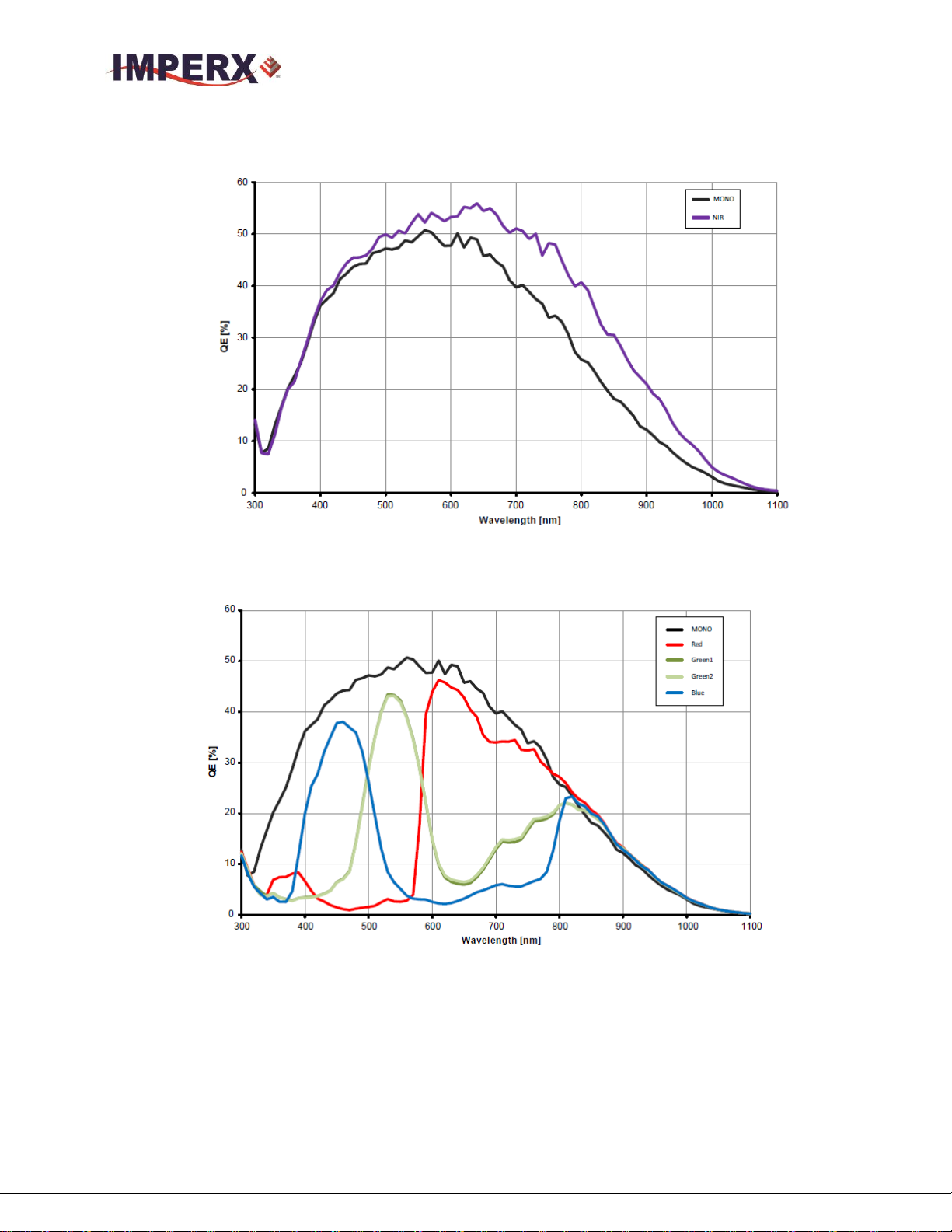
1.3.2 Spectral Sensitivity Curves
Figure 3: Python CMOS mono spectral response
(Monochrome with the cover glass)
Figure 4: Python CMOS typical color spectral response
(Color with Microlens and with cover glass)
Imperx, Inc. Rev 1.7
6421 Congress Ave. 8/26/2016
Boca Raton, FL 33487
+1 (561) 989-0006 16 of 121
Page 17
CHEETAH Hardware User’s Manual
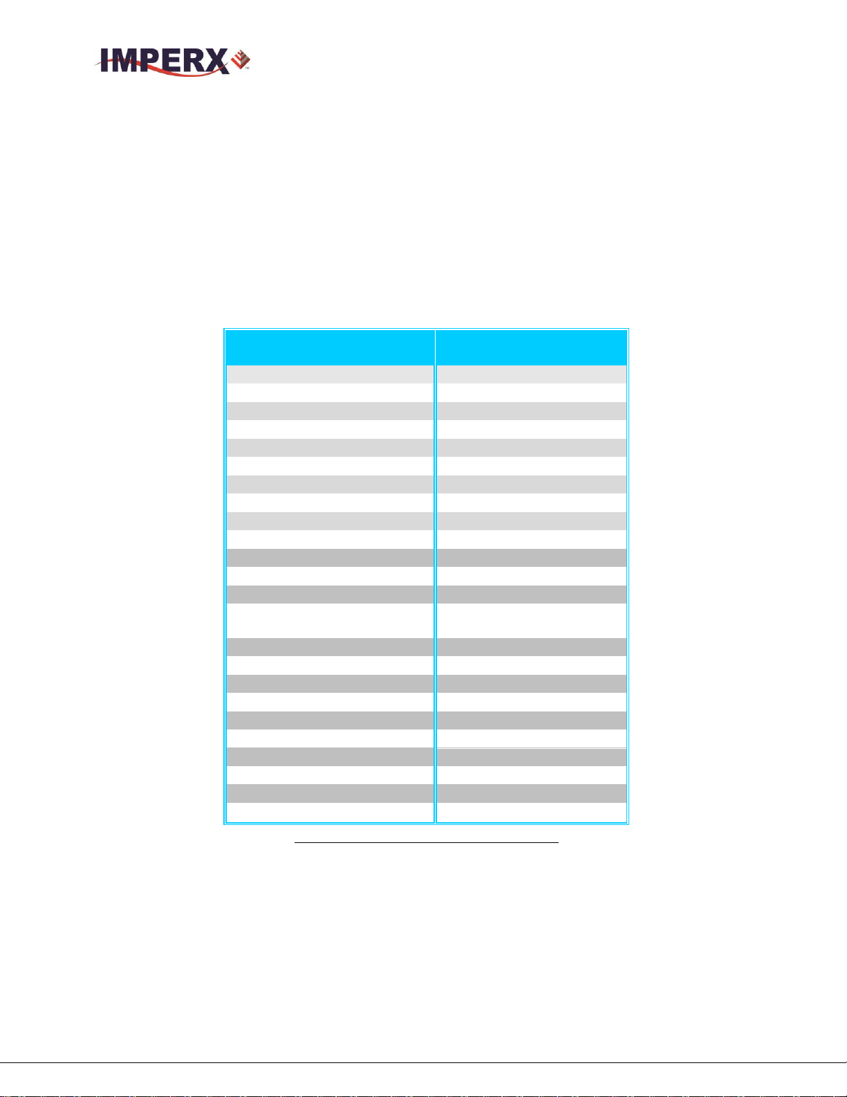
Features / Specifications
C5180/C4181/C4180/C38
80
Shutter Operation
Global only
Exposure time
4 s min
Area of Interest
one
Analog Gain
Up to 10dB
Digital Gain
Up to 24dB
Subsampling
Keep one, skip one
Pixel Averaging (mono)
1x2, 2x1 and 2x2
Auto-White Balance
Yes
Test Image
Static, Dynamic
Defective pixel correction
Static, Dynamic, User DPM
Hot pixel correction
Static, Dynamic, User HPM
Inputs
1-LVTTL / 1-Opto-coupled
Outputs
1-5v TTL / 1-Opto-coupled
Triggers
Programmable Rising/Falling
De-bounce
Pulse Generator
Yes
In-camera Image Processing
2 LUTs
Camera housing
Aluminum
Supply voltage range
10 V to 33 V DC
Upgradeable firmware
Yes
Upgradeable LUT,DPM, FFC
Yes
Operating
- 40.0 to + 85.0 deg C
Environmental – Storage
- 50.0 to + 90.0 deg C
Vibration, Shock
Relative humidity
10% to 90% non-condensing
1.3.3 Bayer Pattern Information
CHEETAH is available with Monochrome or Color CMOS imager. To generate a
color image a set of color filters (Red, Green, and Blue) arranged in a “Bayer”
pattern, are placed over the pixels. The starting color is Red.
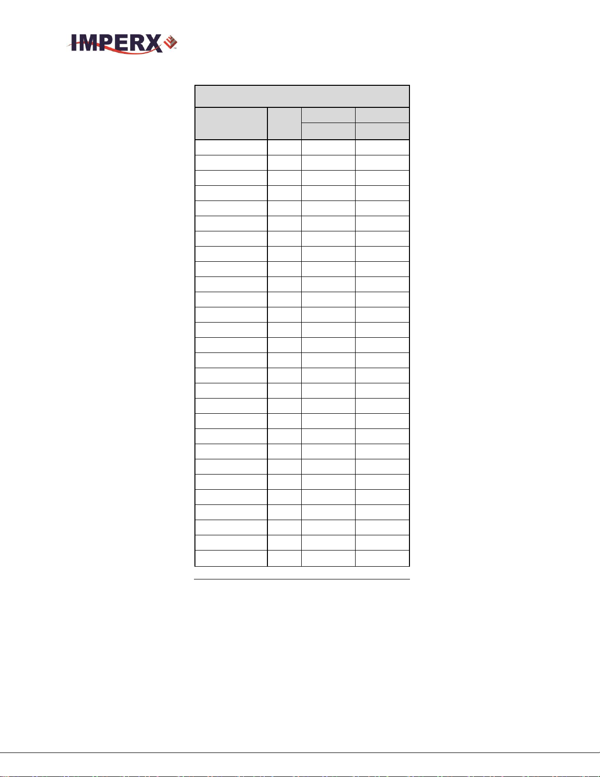
1.4 TECHNICAL SPECIFICATIONS
The following Tables describe features and specifications that relate to all
CHEETAH CLF cameras.
Imperx, Inc. Rev 1.7
6421 Congress Ave. 8/26/2016
Boca Raton, FL 33487
+1 (561) 989-0006 17 of 121
Table 2: Cheetah General Features List
Page 18

CHEETAH Hardware User’s Manual
Specifications
C5180
C4181
Active image resolution
5120 x 5120
4096 x 4096
Active image area (H, V)
23.0 mm x 23.0 mm
32.5 mm Diagonal
18.4 mm x 18.4 mm
26.1 mm Diagonal
Pixel size
4.5 μm
4.5 μm
Video output
Digital, 8/10-bit
Digital, 8/10-bit
Output structure
10-Tap
10-Tap
Data clock
85 MHz
85 MHz
Camera interface
DECA/Full/Medium or Base CL
DECA/Full/Medium or Base CL
Connector
Dual HDR (26-pin mini CL)
Dual HDR (26-pin mini CL)
Maximum frame rate
26 fps (10-bit), 32 fps (8-bit)
40 fps (10-bit), 50 fps (8-bit)
Dynamic Range
59 dB
59 dB
Shutter speed
4s to 1 sec
4s to 1 sec
Area of Interest
One
One
Analog gain
0 to 10dB (8 & 10-bit)
0 to 10dB (8 & 10-bit)
Digital gain
0 to 24dB
0 to 24dB
Black level offset
0 to 1024, 1/step
0 to 1024 1/step
User LUT
2 LUTs: Gamma, User LUT
2 LUTs: Gamma, User LUT
Hardware trigger
Asynchronous
Asynchronous
Strobe Modes
Programmable Width, Delay
, Programmable Width, Delay
Trigger Sources
External , Pulse Generator,
Computer
External, Pulse Generator,
Computer
Trigger features
Rising/Falling edge, De-glitch,
Delay, Strobe
Rising/Falling edge, De-glitch,
Delay, Strobe
Size (W x H x L) - CLB
(72.0 x 72.0 x 39.8) mm
(72.0 x 72.0 x 39.8) mm
Weight
385 g
385 g
Lens Mount
F-Mount, 35mm format
F-Mount– 35mm format
Power:
12V / XX A
12V / XX A
Imperx, Inc. Rev 1.7
6421 Congress Ave. 8/26/2016
Boca Raton, FL 33487
+1 (561) 989-0006 18 of 121
Page 19

CHEETAH Hardware User’s Manual
Specifications
C4180
C3880
Active image resolution
4096 x 3072
3880 x 2896
Active image area (H, V)
18.4 mm x 13.8mm
23.0 mm Diagonal
17.5 mm x 13.0 mm
21.8 mm Diagonal
Pixel size
4.5 μm
4.5 μm
Video output
Digital, 8/10-bit
Digital, 8/10-bit
Output structure
10-Tap
10-Tap
Data clock
85 MHz
85 MHz
Camera interface
DECA/Full/Medium or Base CL
DECA/Full/Medium or Base CL
Connector
Dual HDR (26-pin mini CL)
Dual HDR (26-pin mini CL)
Maximum frame rate
54 fps (10-bit), 67 fps (8-bit)
60 fps (10-bit), 75 fps (8-bit)
Dynamic Range
59 dB
59 dB
Shutter speed
4 s to 1 sec
4 s to 1 sec
Area of Interest
One
One
Analog gain
0 to 10dB
0 to 10dB
Digital gain
0 to 24dB
0 to 24dB
Black level offset
0 to 1024, 1/step
0 to 1024 1/step
User LUT
2 LUTs: Gamma, User LUT
2 LUTs: Gamma, User LUT
Hardware trigger
Asynchronous
Asynchronous
Strobe Modes
Programmable Width, Delay
, Programmable Width, Delay
Trigger Sources
External , Pulse Generator,
Computer
External, Pulse Generator,
Computer
Trigger features
Rising/Falling edge, De-glitch,
Delay, Strobe
Rising/Falling edge, De-glitch,
Delay, Strobe
Size (W x H x L) - CLB
(72.0 x 72.0 x 39.8) mm
(72.0 x 72.0 x 39.8) mm
Weight
385 g
385 g
Lens Mount
F-Mount, 35mm format
F-Mount– 35mm format
Power:
12V / XX A
12V / XX A
Table 3: Cheetah C5180, C4181, C4180, C3880 Specifications
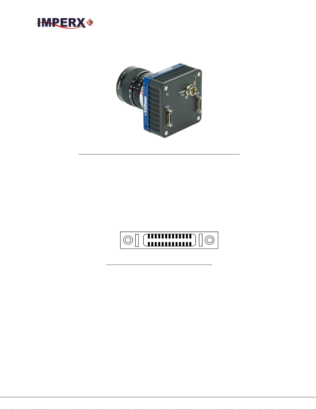
1.5 CAMERA CONNECTIVITY
1.5.1 CLF (Full) - Camera Link (CL) Output
The interface between the CHEETAH cameras and outside equipment is done via 2
connectors and one LED, located on the back panel of the camera – Figure 5.
1. Two camera outputs – standard Full Camera Link Mini connectors provides data,
sync, control, and serial interface.
2. Male 12-pin Power Connector – provides power and I/O interface.
3. USB type B programming/SPI connector.
4. Status LED – indicates the status of the camera – refer to Status LED section.
Imperx, Inc. Rev 1.7
6421 Congress Ave. 8/26/2016
Boca Raton, FL 33487
+1 (561) 989-0006 19 of 121
Page 20
CHEETAH Hardware User’s Manual
1
14
13
26
5. Model / Serial Number – shows camera model and serial number.
Figure 5: CLF Camera back panel / Deca, Full, Medium or Base
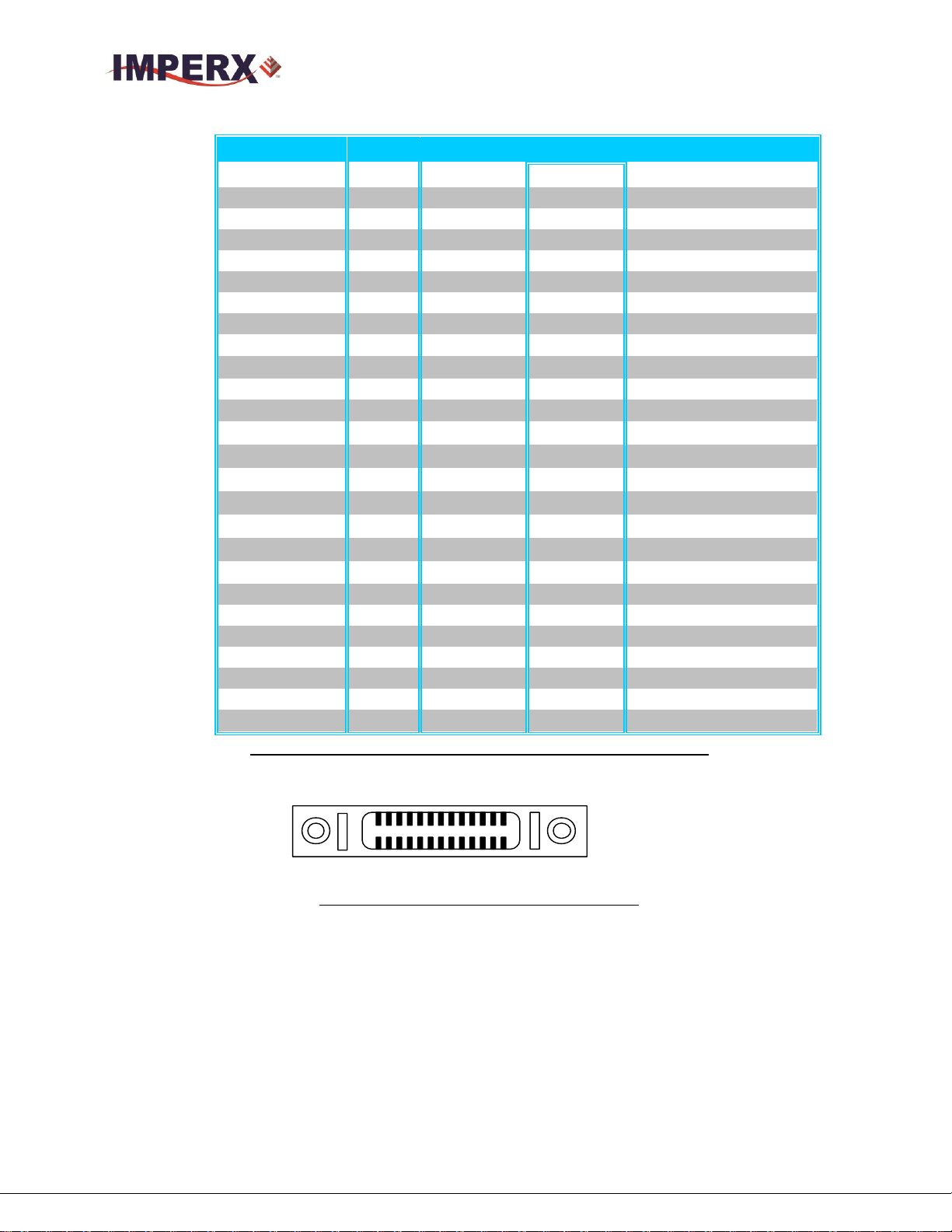
1.5.2 Camera Link Full Signal Mapping
Camera data output is compliant with Deca (80-bit), Full (64-bit), Medium (48-bit)
and Base (24-bit) Camera Link standard, up to 80 data bits, 4 sync signals (LVAL,
FVAL, DVAL and User Out), 1 reference clock, 2 external inputs CC1, CC2 and a
bi-directional serial interface. The camera link output connectors are shown in
Figure 6 and 7, and the corresponding bit and port mapping is described below.
Figure 6: CLF Camera output connector 1
Imperx, Inc. Rev 1.7
6421 Congress Ave. 8/26/2016
Boca Raton, FL 33487
+1 (561) 989-0006 20 of 121
Page 21
CHEETAH Hardware User’s Manual
Cable Name
Pin
CL Signal
Type
Description
Base Wire
1
12 VDC Power
Power
Power Base
Base Wire
14
Power Return
Ground
Ground
- PAIR 1
2
- X 0
LVDS - Out
Camera Link Channel Tx
+ PAIR 1
15
+ X 0
LVDS - Out
Camera Link Channel Tx
- PAIR 2
3
- X 1
LVDS - Out
Camera Link Channel Tx
+ PAIR 2
16
+ X 1
LVDS - Out
Camera Link Channel Tx
- PAIR 3
4
- X 2
LVDS - Out
Camera Link Channel Tx
+ PAIR 3
17
+ X 2
LVDS - Out
Camera Link Channel Tx
- PAIR 4
5
- X CLK
LVDS - Out
Camera Link Clock Tx
+ PAIR 4
18
+ X CLK
LVDS - Out
Camera Link Clock Tx
- PAIR 5
6
- X 3
LVDS - Out
Camera Link Channel Tx
+ PAIR 5
19
+ X 3
LVDS - Out
Camera Link Channel Tx
+ PAIR 6
7
+ SerTC
LVDS - In
Serial Data Receiver
- PAIR 6
20
- SerTC
LVDS - In
Serial Data Receiver
- PAIR 7
8
- SerTFG
LVDS - Out
Serial Data Transmitter
+ PAIR 7
21
+ SerTFG
LVDS - Out
Serial Data Transmitter
- PAIR 8
9
- CC 1
LVDS - In
User Selectable Input
+ PAIR 8
22
+ CC 1
LVDS - In
User Selectable Input
+ PAIR 9
10
+ CC2
LVDS - In
User Selectable Input
- PAIR 9
23
- CC2
LVDS - In
User Selectable Input
- PAIR 10
11
N/C
N/C
N/C
+ PAIR 10
24
N/C
N/C
N/C
+ PAIR 11
12
N/C
N/C
N/C
- PAIR 11
25
N/C
N/C
N/C
Base Wire
13
Power Return
Ground
Ground
Base Wire
26
12 VDC Power
Power
Power Base
1
14
13
26
Table 4: CLF Camera Output Connector 1 – Signal Mapping
Figure 7: CLF Camera output connector 2
Imperx, Inc. Rev 1.7
6421 Congress Ave. 8/26/2016
Boca Raton, FL 33487
+1 (561) 989-0006 21 of 121
Page 22
CHEETAH Hardware User’s Manual
Cable Name
Pin
CL Signal
Type
Description
Base Wire
1
12 VDC Power
Power
Power Base
Base Wire
14
Power Return
Ground
Ground
- PAIR 1
2
- Y 0
LVDS - Out
Camera Link Channel Tx
+ PAIR 1
15
+ Y 0
LVDS - Out
Camera Link Channel Tx
- PAIR 2
3
- Y 1
LVDS - Out
Camera Link Channel Tx
+ PAIR 2
16
+ Y 1
LVDS - Out
Camera Link Channel Tx
- PAIR 3
4
- Y 2
LVDS - Out
Camera Link Channel Tx
+ PAIR 3
17
+ Y 2
LVDS - Out
Camera Link Channel Tx
- PAIR 4
5
- Y CLK
LVDS - Out
Camera Link Clock Tx
+ PAIR 4
18
+ Y CLK
LVDS - Out
Camera Link Clock Tx
- PAIR 5
6
- Y 3
LVDS - Out
Camera Link Channel Tx
+ PAIR 5
19
+ Y 3
LVDS - Out
Camera Link Channel Tx
+ PAIR 6
7
unused
LVDS - In
Serial Data Receiver
- PAIR 6
20
unused
LVDS - In
Serial Data Receiver
- PAIR 7
8
- Z 0
LVDS - Out
Camera Link Channel Tx
+ PAIR 7
21
+ Z 0
LVDS - Out
Camera Link Channel Tx
- PAIR 8
9
- Z 1
LVDS - Out
Camera Link Channel Tx
+ PAIR 8
22
+ Z 1
LVDS - Out
Camera Link Channel Tx
+ PAIR 9
10
- Z 2
LVDS - Out
Camera Link Channel Tx
- PAIR 9
23
+ Z 2
LVDS - Out
Camera Link Channel Tx
- PAIR 10
11
-Z CLK
LVDS - Out
Camera Link Clock Tx
+ PAIR 10
24
+ Z CLK
LVDS - Out
Camera Link Clock Tx
+ PAIR 11
12
- Z 3
LVDS - Out
Camera Link Channel Tx
- PAIR 11
25
+Z 3
LVDS - Out
Camera Link Channel Tx
Base Wire
13
Power Return
Ground
Ground
Base Wire
26
12 VDC Power
Power
Power Base
Table 5: CLF Camera Output Connector 2 – Signal Mapping
1.5.3 Camera Link Physical Layer to Camera Link Receiver Bits
The timing diagram below describes how the Camera Link bits are transmitted over the physical
link. In the timing diagram below, X0, X1, X2 and X3 are the physical connections. Seven data
packets of four bits each are sent during each clock cycle and provide the 28 Camera Link Bits. In
the figure 8 below, Camera Link bits 0, 8, 19 and 27 are received over X0 to X3 in the first transfer
and bits 1, 9, 20 and 5 are received in the second transfer cycle. The timing for Y0 to Y3 and Z0 to
Z3 physical connections is the same as X0 to X3.
Imperx, Inc. Rev 1.7
6421 Congress Ave. 8/26/2016
Boca Raton, FL 33487
+1 (561) 989-0006 22 of 121
Page 23

CHEETAH Hardware User’s Manual
Figure 8: Camera Link bit sequence over the physical connection
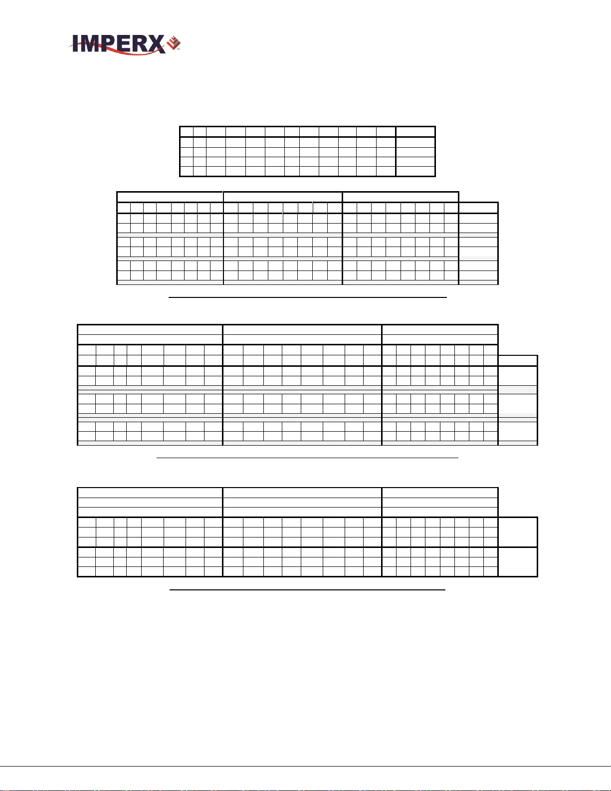
1.5.4 Camera Link Bit to Port Bit assignments
Tables 6-8 describe how the Camera Link Receiver bits received from X0-X3, Y0-Y3 and Z0-Z3
physical connections on CL connectors #1 and are translated into the Camera Link Port bits based
on the selected Camera Link Configuration: Base, Medium, Full or Deca.
Imperx, Inc. Rev 1.7
6421 Congress Ave. 8/26/2016
Boca Raton, FL 33487
+1 (561) 989-0006 23 of 121
Page 24
CHEETAH Hardware User’s Manual
Camera Link X0-X3
CL_RCVR_Bits
Base
10tap8bit
8tap10bit
Deca
Deca
0
A0
A0
A0
1
A1
A1
A1
2
A2
A2
A2
3
A3
A3
A3
4
A4
A4
A4
5
A7
A5
A7
6
A5
A6
A5
7
B0
A7
B0
8
B1
B0
B1
9
B2
B1
B2
10
B6
B2
B6
11
B7
B3
B7
12
B3
B4
B3
13
B4
B5
B4
14
B5
B6
B5
15
C0
B7
C0
16
C6
C0
C6
17
C7
C1
C7
18
C1
C2
C1
19
C2
C3
C2
20
C3
C4
C3
21
C4
C5
C4
22
C5
C6
C5
23
SPR
C7
I1
24
LVAL
LVAL
LVAL
25
FVAL
FVAL
FVAL
26
DVAL
D0
I0
27
A6
D1
A6
Table 6: Camera Link Connector #1 (X0-X3)
Imperx, Inc. Rev 1.7
6421 Congress Ave. 8/26/2016
Boca Raton, FL 33487
+1 (561) 989-0006 24 of 121
Page 25

CHEETAH Hardware User’s Manual
Camera Link Y0-Y3
CL_RCVR_Bits
Med
10tap8bit
8tap10bit
Deca
Deca
0
D0
D2
D0
1
D1
D3
D1
2
D2
D4
D2
3
D3
D5
D3
4
D4
D6
D4
5
D7
D7
D7
6
D5
E0
D5
7
E0
E1
E0
8
E1
E2
E1
9
E2
E3
E2
10
E6
E4
E6
11
E7
E5
E7
12
E3
E6
E3
13
E4
E7
E4
14
E5
F0
E5
15
F0
F1
F0
16
F6
F2
F6
17
F7
F3
F7
18
F1
F4
F1
19
F2
F5
F2
20
F3
F6
F3
21
F4
F7
F4
22
F5
G0
F5
23
SPR
G1
I4
24
LVAL
G2
LVAL
25
FVAL
G3
I2
26
DVAL
G4
I3
27
D6
LVAL
D6
Table 7: Camera Link Connector #2 (Y0-Y3)
Imperx, Inc. Rev 1.7
6421 Congress Ave. 8/26/2016
Boca Raton, FL 33487
+1 (561) 989-0006 25 of 121
Page 26

CHEETAH Hardware User’s Manual
Camera Link Z0-Z3
CL_RCVR_Bits
Full
10tap8bit
8tap10bit
Deca
Deca
0
G0
G5
G0
1
G1
G6
G1
2
G2
G7
G2
3
G3
H0
G3
4
G4
H1
G4
5
G7
H2
G7
6
G5
H3
G5
7
H0
H4
H0
8
H1
H5
H1
9
H2
H6
H2
10
H6
H7
H6
11
H7
I0
H7
12
H3
I1
H3
13
H4
I2
H4
14
H5
I3
H5
15 - I4
I5
16 - I5
J3
17 - I6
J4
18 - I7
I6
19 - J0
I7
20 - J1
J0
21 - J2
J1
22 - J3
J2
23
SPR
J4
J7
24
LVAL
J5
LVAL
25
FVAL
J6
J5
26
DVAL
J7
J6
27
G6
LVAL
G6
Table 8: Camera Link Connector #2 (Z0-Z3)
Imperx, Inc. Rev 1.7
6421 Congress Ave. 8/26/2016
Boca Raton, FL 33487
+1 (561) 989-0006 26 of 121
Page 27
CHEETAH Hardware User’s Manual
1x8
2x8
1x10
2x10
1x12
2x12
4x8
4x10
4x12
8x8
10x8
8x10
MODE
Base
Medium
Full
Deca
Por
t C
Por
t B
Por
t A
c7
c6
c5
C4
c3
c2
c1
c0
b7
b6
b5
b4
b3
b2
b1
b0
a7
a6
a5
a4
a3
a2
a1
a0
MODE
A7
A6
A5
A4
A3
A2
A1
A0
1x8
B7
B6
B5
B4
B3
B2
B1
B0
A7
A6
A5
A4
A3
A2
A1
A0
2x8
A9
A8
A7
A6
A5
A4
A3
A2
A1
A0
1x10
B7
B6
B5
B4
B3
B2
B1
B0
B9
B8
A9
A8
A7
A6
A5
A4
A3
A2
A1
A0
2x10
A11
A10
A9
A8
A7
A6
A5
A4
A3
A2
A1
A0
1x12
B7
B6
B5
B4
B3
B2
B1
B0
B11
B10
B9
B8
A11
A10
A9
A8
A7
A6
A5
A4
A3
A2
A1
A0
2x12
Por
t C
Por
t B
Por
t A
Por
t F
Por
t E
Por
t D
c7
c6
c5
c4
c3
c2
c1
c0
b7
b6
b5
b4
b3
b2
b1
b0
a7
a6
a5
a4
a3
a2
a1
a0 f7
f6
f5
f4
f3
f2
f1
f0
e7
e6
e5
e4
e3
e2
e1
e0
d7
d6
d5
d4
d3
d2
d1
d0
MODE
C7
C6
C5
C4
C3
C2
C1
C0
B7
B6
B5
B4
B3
B2
B1
B0
A7
A6
A5
A4
A3
A2
A1
A0
4x8
D7
D6
D5
D4
D3
D2
D1
D0
B7
B6
B5
B4
B3
B2
B1
B0
B9
B8
A9
A8
A7
A6
A5
A4
A3
A2
A1
A0
4x10
D9
D8
C9
C8
C7
C6
C5
C4
C3
C2
C1
C0
D7
D6
D5
D4
D3
D2
D1
D0
B7
B6
B5
B4
B3
B2
B1
B0
B11
B10
B9
B8
A11
A10
A9
A8
A7
A6
A5
A4
A3
A2
A1
A0
4x12
D11
D10
D9
D8
C11
C10
C9
C8
C7
C6
C5
C4
C3
C2
C1
C0
D7
D6
D5
D4
D3
D2
D1
D0
Por
t C
Por
t B
Por
t A
Por
t F
Por
t E
Por
t D --- Por
t H
Por
t G
c7
c6
c5
c4
c3
c2
c1
c0
b7
b6
b5
b4
b3
b2
b1
b0
a7
a6
a5
a4
a3
a2
a1
a0
f7
f6
f5
f4
f3
f2
f1
f0
e7
e6
e5
e4
e3
e2
e1
e0
d7
d6
d5
d4
d3
d2
d1
d0 h7
h6
h5
h4
h3
h2
h1
h0
g7
g6
g5
g4
g3
g2
g1
g0
MODE
C7
C6
C5
C4
C3
C2
C1
C0
B7
B6
B5
B4
B3
B2
B1
B0
A7
A6
A5
A4
A3
A2
A1
A0
8x8
F7
F6
F5
F4
F3
F2
F1
F0
E7
E6
E5
E4
E3
E2
E1
E0
D7
D6
D5
D4
D3
D2
D1
D0
H7
H6
H5
H4
H3
H2
H1
H0
G7
G6
G5
G4
G3
G2
G1
G0
1.5.5 Camera Link Port assignments based on selected output configuration
Table 9: Image data bit-to-port assignments– Base modes
Table 10: Image data bit-to-port assignments– Medium modes
Table 11: Image data bit-to-port assignments– Full mode
Imperx, Inc. Rev 1.7
6421 Congress Ave. 8/26/2016
Boca Raton, FL 33487
+1 (561) 989-0006 27 of 121
Page 28
CHEETAH Hardware User’s Manual
Por
t C
Por
t B
Por
t A Por
t F
Por
t E
Por
t D Por
t I
Por
t H
Por
t G --- --- Por
t J
c7
c6
c5
c4
c3
c2
c1
c0
b7
b6
b5
b4
b3
b2
b1
b0
a7
a6
a5
a4
a3
a2
a1
a0
f7
f6
f5
f4
f3
f2
f1
f0
e7
e6
e5
e4
e3
e2
e1
e0
d7
d6
d5
d4
d3
d2
d1
d0
i7
i6
i5
i4
i3
i2
i1
i0
h7
h6
h5
h4
h3
h2
h1
h0
g7
g6
g5
g4
g3
g2
g1
g0
j7
j6
j5
j4
j3
j2
j1
j0
MODE
C7
C6
C5
C4
C3
C2
C1
C0
B7
B6
B5
B4
B3
B2
B1
B0
A7
A6
A5
A4
A3
A2
A1
A0
10x8
F7
F6
F5
F4
F3
F2
F1
F0
E7
E6
E5
E4
E3
E2
E1
E0
D7
D6
D5
D4
D3
D2
D1
D0
I7
I6
I5
I4
I3
I2
I1
I0
H7
H6
H5
H4
H3
H2
H1
H0
G7
G6
G5
G4
G3
G2
G1
G0
J7
J6
J5
J4
J3
J2
J1
J0 C9
C8
C7
C6
C5
C4
C3
C2
B9
B8
B7
B6
B5
B4
B3
B2
A9
A8
A7
A6
A5
A4
A3
A2
8x10
F9
F8
F7
F6
F5
F4
F3
F2
E9
E8
E7
E6
E5
E4
E3
E2
D9
D8
D7
D6
D5
D4
D3
D2
D1
D0
C1
C0
B1
B0
A1
A0
H9
H8
H7
H6
H5
H4
H3
H2
G9
G8
G7
G6
G5
G4
G3
G2
H1
H0
G1
G0
F1
F0
E1
E0
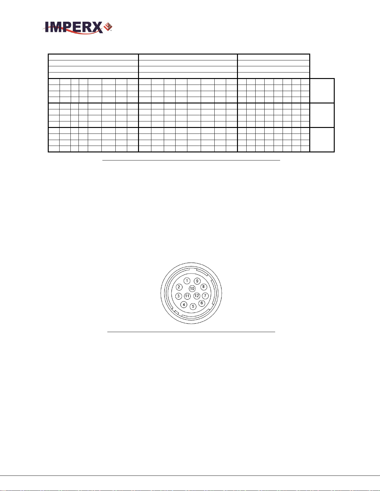
Table 12: Image data bit-to-port assignments– Deca modes
1.5.6 Camera Power Connector
The male 12-pin Hirose connector provides power and all external input/output
signals supplied to the camera. Refer to Fig 9 for connector pin-outs. Refer to Table
13 for corresponding pin mapping. The connector is a male HIROSE type miniature
locking receptacle #HR10A-10R-12PB (71). The optionally purchased power supply
is shipped with a power cable which terminates in a female HIROSE plug #HR10A10P-12S (73).
Figure 9: Camera Power Connector (Viewed from rear)
Imperx, Inc. Rev 1.7
6421 Congress Ave. 8/26/2016
Boca Raton, FL 33487
+1 (561) 989-0006 28 of 121
Page 29

CHEETAH Hardware User’s Manual
Pin
Signal
Type
Description
1
12 VDC Return
Ground Return
12 VDC Main Power Return
2
+ 12 VDC
Power - Input
+ 12 VDC Main Power
3
NC
–NC
Reserved for future RS-232
4
NC
NC
Reserved for future RS-232
5
GP OUT 2
Opto- Switch contact 2
General Purpose Output 2-
6
GP Out 1 RTN
TTL Ground Return
General Purpose Output 1 Return
7
GP OUT 1
TTL OUT 1
General Purpose Output 1
8
GP IN 1
Opto-isolated IN 1
General Purpose Input 1
9
GP IN 2
TTL/LVTTL IN 2
General Purpose Input 2
10
GP IN 1 Return
Ground Return IN1
General Purpose Input 1 Return
11
GP IN 2 Return
LVTTL Ground Return IN2
General Purpose Input 2 Return
12
GP OUT 2
Opto-Switchcontact 1
General Purpose Output 2+
Table 13: Camera Power Connector Pin Mapping
1.6 MECHANICAL, OPTICAL, and ENVIRONMENTAL
1.6.1 Mechanical
The camera housing is manufactured using high quality zinc-aluminum alloy and
anodized aluminum. For maximum flexibility the camera has eight (8) M3X0.5mm
mounting screws, located towards the front and the back. An additional plate with ¼20 UNC (tripod mount) and hardware is shipped with each camera.. All dimensions
are in millimeters.
1.6.2 Optical
The camera (72 x 72) mm cross-section comes with an adapter for F-mount lenses,
which have a 46.50 mm back focal distance.
The camera performance and signal to noise ratio depends on the illumination
(amount of light) reaching the sensor and the exposure time. Always try to balance
these two factors. Unnecessarily long exposure will increase the amount of noise and
thus decrease the signal to noise ratio.
The cameras are very sensitive in the IR spectral region. All color cameras have an
IR cut-off filter installed. The monochrome cameras come without IR cut filter. If
Imperx, Inc. Rev 1.7
6421 Congress Ave. 8/26/2016
Boca Raton, FL 33487
+1 (561) 989-0006 29 of 121
Page 30

CHEETAH Hardware User’s Manual
necessary, an IR filter (1 mm thickness or less) can be inserted under the front lens
bezel.
CAUTION NOTE
1. Avoid direct exposure to a high intensity light source (such as a laser beam).
This may damage the camera optical sensor!
2. Avoid foreign particles on the surface of the imager.
1.6.3 Environmental
The camera is designed to operate from -400 to 850 C in a dry environment. The
relative humidity should not exceed 80% non-condensing. Always keep the camera
as cool as possible. Always allow sufficient time for temperature equalization, if the
camera was kept below 00 C!
The camera should be stored in a dry environment with the temperature ranging
from -500 to + 900 C.
CAUTION NOTE
1. Avoid direct exposure to moisture and liquids. The camera housing is not
hermetically sealed and any exposure to liquids may damage the camera
electronics!
2. Avoid operating in an environment without any air circulation, in close
proximity to an intensive heat source, strong magnetic or electric fields.
3. Avoid touching or cleaning the front surface of the optical sensor. If the sensor
needs to be cleaned, use soft lint free cloth and an optical cleaning fluid. Do not
use methylated alcohol!
Imperx, Inc. Rev 1.7
6421 Congress Ave. 8/26/2016
Boca Raton, FL 33487
+1 (561) 989-0006 30 of 121
Page 31

CHEETAH Hardware User’s Manual
1.6.4 Mechanical Drawings
1.6.4.1 C5180, C4181, C4180 and C3880 Drawings
Figure 10: C5180, C4181, C4180 and C3880 Mechanical Drawings
Imperx, Inc. Rev 1.7
6421 Congress Ave. 8/26/2016
Boca Raton, FL 33487
+1 (561) 989-0006 31 of 121
Page 32

CHEETAH Hardware User’s Manual
Chapter 2 – Camera Features
Camera Features
This chapter discusses the camera’s features and their use.
Imperx, Inc. Rev 1.7
6421 Congress Ave. 8/26/2016
Boca Raton, FL 33487
+1 (561) 989-0006 32 of 121
Page 33

CHEETAH Hardware User’s Manual
2.1 EXPOSURE CONTROL
2.1.1 Internal Exposure Control - Electronic Shutter
In global shutter, all pixels in the array are reset at the same time, allowed to collect
signal during the exposure time and then the image is transferred to a nonphotosensitive region within each pixel. Once the image is transferred to the nonphotosensitive region, then the readout of the array begins. In this way, all pixels
capture the image during the same time period reducing any image artifacts due to
motion within the scene. The maximum exposure is frame time dependent and the
minimum exposure is ~ 4 microseconds.
The camera normally overlaps the exposure and readout times as shown in Figure
Figure 11.
Figure 11: Global Shutter with 8.33mS exposure time
2.1.2 External exposure control
The camera exposure can be controlled using an external pulse, supplied to the
camera. The pulse duration determines the exposure. In global shutter mode, the
minimum exposure time is about 4 to 6 micro-seconds. Please refer to 2.5 Camera
Triggering and 2.14 I/O control sections.
Imperx, Inc. Rev 1.7
6421 Congress Ave. 8/26/2016
Boca Raton, FL 33487
+1 (561) 989-0006 33 of 121
Page 34

CHEETAH Hardware User’s Manual
2.2 FRAME TIME CONTROL
2.2.1 Internal Line and Frame Time Control
The camera speed (frame rate) depends on the CMOS “read-out” time – the time
necessary to read all the pixels out of the CMOS imager. The frame rate can be
calculated using the following Formula 1.1:
Frame rate [fps] = 1 / read-out time [sec] (1.1)
2.2.1.1 Pixel Clock Line Rate Control
The user can program the camera to run slower than the fastest speed preserving the
camera full resolution by extending the camera frame time (the time required to read
the entire frame out of the CMOS imager). The time to readout a line is controlled
by the Pixel Clock Rate control in the Acquisition Sub-Menu. Since the image
sensor readout speed exceeds the Camera Link interface output rate, the Pixel Clock
Rate control is used to match the camera output rate to the frame grabber capture
rate.
The Pixel Clock should always be adjusted to the maximum rate possible without the
frame grabber missing or skipping data. In this way, the dark current generated
within the pixel and the dark current noise is minimized.
2.2.1.2 Programmable Frame Time Control
Once the Pixel Clock has been adjusted to minimize the line readout time, the user
can increase the frame time by using the Programmable Frame Time feature. When
programmable frame time control is enabled, the frame is readout and then the
camera idles inserting a vertical blanking period at the end of the frame readout to
provide the desired frame rate.
In this way, the user can reduce the camera output frame rate to match the
application requirements. The frame time can be reduced to about ~1 second with a
precision of 1 micro-second. The programmable frame time control can be used to
support exposure times longer than the time necessary to readout the image sensor.
2.2.1.3 Zero-Row Overhead (ROT) Control
A Row-Overhead time (ROT) control is provided and the control is called: “ZeroRow Overhead Time” (Zero-ROT). Disabling Zero-ROT adds one micro-second of
blanking time at the end of each row to further reduce the line rate. Zero-ROT
should only be used as a last resort and only when decreasing Pixel Clock line rate
control to the minimum value still results in frame grabber overruns. Zero-ROT must
Imperx, Inc. Rev 1.7
6421 Congress Ave. 8/26/2016
Boca Raton, FL 33487
+1 (561) 989-0006 34 of 121
Page 35

CHEETAH Hardware User’s Manual
Camera
Bit Depth
Output
Data Rate
(Gbit/s)
Full Resolution
Imperx
VCE-CLPCIe04
(fps)
Full
Resolution
Frame Rate
(fps)
C5180
8,10
2-Tap (Base)
2.04
6.4
7
8,10
4-Tap (Medium)
4.08
12.8
14
8-Bit
8-Tap (Full)
6.12
25.6
28
10-Bit
8-Tap (Full)
6.12
20.2
23
8-Bit
10-Tap (Deca)
6.8
25.8
32
Camera
Bit Depth
Output
Data
Rate
(Gbit/s)
Full Resolution
Frame Rate (fps)
C4181
8,10
2-Tap (Base)
2.04
11
8,10
4-Tap (Medium)
4.08
23
8-Bit
8-Tap (Full)
5.44
35
10-Bit
8-Tap (Deca)
6.8
35
8-Bit
10-Tap (Deca)
6.8
50
always be disabled and is not supported when using pixel averaging is used and
when Camera Link Base output is selected.
CAUTION NOTE
1. If the frame time is greater than 50ms, the camera vibration must be kept to a
minimum otherwise a motion induced smear will appear on the image.
2.2.2 Camera Output Control
CHEETAH camera supports the following Camera Link Outputs: 2-Tap, 4-Tap, 8Tap or 10-Tap Output. This corresponds to Base, Medium, Full or Deca Output.
These camera settings combined with the output bit-depth (8 or 10-bit) to control the
total the interface bandwidth. The output interface clock speed for the Cheetah
Camera is 85-MHz (Camera Link Spec is 85 MHz maximum) It is important to
match the camera’s output to the frame grabber.
Select a frame grabber or camera output based upon the following criteria of data
rate:
CLF-C5180
Imperx, Inc. Rev 1.7
6421 Congress Ave. 8/26/2016
Boca Raton, FL 33487
+1 (561) 989-0006 35 of 121
Table 14: C5180 frame rates vs output taps
CLF-C4181
Table 15: C4181 frame rates vs output taps
Page 36

CHEETAH Hardware User’s Manual
Camera
Bit Depth
Output
Data
Rate
(Gbit/s)
Full Resolution
Frame Rate (fps)
C4180
8,10
2-Tap (Base)
2.04
14
8,10
4-Tap (Medium)
4.08
30
8-Bit
8-Tap (Full)
5.44
47
10-Bit
8-Tap (Deca)
6.8
47
8-Bit
10-Tap (Deca)
6.8
67
Camera
Bit Depth
Output
Data
Rate
(Gbit/s)
Full Resolution
Frame Rate (fps)
C3880
8,10
2-Tap (Base)
2.04
16
8,10
4-Tap (Medium)
4.08
35
8-Bit
8-Tap (Full)
5.44
54
10-Bit
8-Tap (Deca)
6.8
54
8-Bit
10-Tap (Deca)
6.8
75
CLF-C4180
Table 16: C4180 frame rates vs output taps
CLF-C3880
2.3 AREA OF INTEREST
Imperx, Inc. Rev 1.7
6421 Congress Ave. 8/26/2016
Boca Raton, FL 33487
+1 (561) 989-0006 36 of 121
Table 17: C3880 frame rates vs output taps
2.3.1 Overview
For some applications the user may not need the entire image, but only a portion of
it. To accommodate this requirement, CHEETAH provides one Region of Interest
(ROI) also known as Area of Interest (AOI). The camera offers a pre-programmed
quad full HD (QFD) AOI (3840 x 2160 resolution) to simplify camera setup for
QFHD applications. The Cheetah also allows custom AOIs as described below.
2.3.2 Horizontal and Vertical Window
The starting and ending point for each AOI can be set independently in horizontal
direction (Horizontal Window) and vertical direction (Vertical Window), by setting
the window (H & V) offset and (H & V) size – Figure 12. The minimum window
size is 320 (H) x 2 (V) pixel/line and the horizontal dimension is limited to multiples
Page 37

CHEETAH Hardware User’s Manual
of 8 pixels. In normal operation, the AOI defines the number of columns and rows
output. However, subsampling and averaging modes can be applied to the AOI
reducing the number of rows and columns output even further. Using the AOI
function and subsampling / averaging modes will have the effect of increasing the
camera frame rate. The maximum horizontal window size (H) and the vertical
window size (V) are determined by image full resolution (For example, C5180: 5180
x 5180 or C4181: 4096 x 4096).
Figure 12: Horizontal and vertical window positioning
Note: Color version users – when AOI is enabled, for proper color
reconstruction and WB ‘Offset X’ and ‘Offset Y’ must be an even number.
2.3.3 Factors Impacting Frame Rate
The camera frame rate depends upon a number of variables including the exposure
time, number of rows and columns in the AOI, the amount of decimation within the
image and the bandwidth of the output interface.
AOI size: The camera frame rate will increase by decreasing either the number of
columns or number of rows readout. Changing the number of rows readout will
result in the largest change in frame rate.
Exposure Time: In free-running mode, the camera overlaps the exposure time and
image readout. In trigger mode, the exposure and readout time need not overlap and
long exposure times will decrease frame rate.
Imperx, Inc. Rev 1.7
6421 Congress Ave. 8/26/2016
Boca Raton, FL 33487
+1 (561) 989-0006 37 of 121
Page 38

CHEETAH Hardware User’s Manual
C5180 Frame
Rates (fps)
8-bit, CL 10-
taps (FPS)
Full Resolution
32
3840 x 2160
80
1920 x 1080
316
1280 x 720
570
Decimation: The camera supports both sub-sampling and pixel averaging to reduce
the output resolution. Both pixel averaging and sub-sampling increase the image
sensor frame rate, however, sub-sampling decimation offers the largest frame rate
improvement by reducing the number of rows and columns readout from the image
sensor. Sub-sampling and pixel averaging decimation provide about a 2x to 3x
increase in frame rate.
Output Interface Bandwidth: The bandwidth of the output interface can also
impact the maximum achievable frame rate. For example, with Camera Link Base (2
taps selected) and with 10-bit digitization and 10-bit output mode selected, the frame
rate is limited by the output interface bandwidth of 2.04 Gbps.
2.3.3.1 AOI Frame Rate Examples
The Tables below describe resulting frame rate (FR) for various AOIs using Camera
Link Deca output. The frame grabber speed will impact results and values below
assume an x8 speed frame grabber. The camera will calculate and display the actual
frame rate at any horizontal and vertical window selection.
Examples of C5180 Frame Rate performance at full resolution and within selected
AOIs are described in Table 18.
Imperx, Inc. Rev 1.7
6421 Congress Ave. 8/26/2016
Boca Raton, FL 33487
+1 (561) 989-0006 38 of 121
Table 18: C5180 AOI frame rate for various AOIs
Examples of C3880 frame rate performance at full resolution and within selected
AOIs for 8-bit digitization are described in Table 19.
Page 39

CHEETAH Hardware User’s Manual
C3880 Frame
Rates (fps)
8-bit, CL
10-tap
Full Resolution
74
1920 x 1080
388
1280 x 720
689
640 x 480
1009
Table 19: C3880 Maximum Frame Rate for various AOIs
2.4 SUBSAMPLING
2.4.1 Pixel Averaging
The principal objective of the averaging function is to reduce the image resolution
with better final image quality than a sub-sampling function. Sub-sampling as
opposed to averaging has the advantage of increasing the output frame rate by
reducing the number of rows readout, but also introduces aliasing in the final image.
Pixel averaging reduces the output resolution by averaging several pixels together
and has the advantage of reducing aliasing and reducing noise increasing SNR.
Subsampling, however, increases output frame rate more than pixel averaging
It is not possible to apply both averaging and sub-sampling decimation
simultaneously. Zero ROT is not supported when averaging is enabled. Color
cameras do not support pixel averaging.
The graphic below illustrates the concept of 4:1 averaging for a monochrome image sensor.
The values of pixels P1, P2, P3 and P4 are summed together and the result is divided by 4 to
achieve an average of the 4 adjacent pixels.
Figure 13: Monochrome pixel averaging
The averaging feature can be used on the full resolution image or within any area of interest.
If, for example, the area of interest is defined to be quad full HD (3840 x 2160) and 4:1
averaging is selected, the output is 1080P (1920 x 1080)
Imperx, Inc. Rev 1.7
6421 Congress Ave. 8/26/2016
Boca Raton, FL 33487
+1 (561) 989-0006 39 of 121
Page 40

CHEETAH Hardware User’s Manual
2.4.2 Sub-sampling Decimation
Subsampling reduces the number of pixels output by reducing the output frame size,
but maintains the full field of view. If an area of interest (AOI) is selected, then the
field of view of the AOI is maintained.
The C5180, C4181, C4180 and C2880 employ a ‘keep one pixel’, ‘skip one pixel’
sequence. When enabled in both x and y, every other pixel within a line is retained
and every other line within the image is retained.
C4181
Figure 14: Monochrome sub-sampling
Figure 15: Color sub-sampling
Imperx, Inc. Rev 1.7
6421 Congress Ave. 8/26/2016
Boca Raton, FL 33487
+1 (561) 989-0006 40 of 121
Page 41

CHEETAH Hardware User’s Manual
2.5 CAMERA TRIGGERING
2.5.1 Triggering Inputs
In the normal mode of operation, the camera is free running. Using the trigger mode
allows the camera to be synchronized to an external timing pulse. .
There are four input modes available for external triggering – computer (CC),
internal (pulse generator), external and software. Please note that the desired trigger
input has to be mapped to corresponding camera input. For more information, please
refer to Section 2.14: I/O Control.
- “External” – the camera receives the trigger signal coming from the connector
located on the back of the camera.
- “Computer” – the camera receives the trigger signal command from the CC
signals. .
- “Internal” – the camera has a built-in programmable pulse generator – refer to
“Pulse Generator” section. In Internal triggering mode the camera receives the
trigger signal from the internal pulse generator.
- “Software” – the camera expects a single trigger (one clock cycle) generated by
the computer. The user can trigger the camera by depressing the GUI Trigger
button or by writing any data to address 0x6030.
2.5.2 Acquisition and Exposure Control
For each trigger input the user can set the trigger edge, and the debounce (de-glitch)
time.
1. “Triggering Edge” – the user can select the active triggering edge:
- “Rising” – the rising edge will be used for triggering
- “Falling” – the falling edge will be used for triggering
2. “De-bounce” – the trigger inputs are de-bounced to prevent multiple triggering
from ringing triggering pulses. The user has eight choices of de-bounce interval:
- “Off” – no de-bounce (default)
- “10” s, “50” s, “100” s, “500” s de-bounce interval
- “1.0” ms, “5.0” ms, “10.0” ms de-bounce interval
3. “Exposure Time” – the exposure for all frames can be set in two ways:
Imperx, Inc. Rev 1.7
6421 Congress Ave. 8/26/2016
Boca Raton, FL 33487
+1 (561) 989-0006 41 of 121
Page 42

CHEETAH Hardware User’s Manual
- “Pulse Width” – the trigger pulse width (duration) determines the exposure
subject to limitations.
- “Internal” – the camera internal exposure register determines the exposure.
CAUTION NOTE
1. The de-bounce interval MUST be smaller than the trigger pulse duration. Adjust
the interval accordingly.
2. When Triggering is enabled “Internal Exposure timing” is not active
2.5.3 Triggering modes
A. Exposure Control
When trigger mode is enabled, the exposure time can be set using either the internal
exposure timer or the trigger pulse width.
When the trigger mode is selected, the camera idles and waits for a trigger signal.
Upon receiving the trigger signal, the camera starts integration for the frame,
completes the integration and the image is readout. If the next trigger is received
prior to completion of the readout, the exposure and readout will be overlapped as
shown in Figure 16 and 17. The exposure time can be set manually using the internal
exposure register setting as shown in Figure 16 or set by the duration of the trigger
pulse as shown in Figure 17. The minimum exposure time using the trigger pulse
width is 2 micro-seconds.. Upon completing the readout, if another trigger pulse has
not been received, the trigger cycle is completed and the camera idles awaiting the
next trigger pulse.
Figure 16: Trigger Mode (Internal Exposure Control)
Imperx, Inc. Rev 1.7
6421 Congress Ave. 8/26/2016
Boca Raton, FL 33487
+1 (561) 989-0006 42 of 121
Page 43

CAUTION: When using the internal exposure timer, if the next trigger is received
prior to the completion of the previous exposure time, the trigger will be ignored.
2.6 STROBES
The camera can provide up to two strobe pulses for synchronization with an external
light source, additional cameras or other peripheral devices. The user can set each
strobes pulse duration and the delay with respect to the start of the exposure period
or the start of the readout period. The maximum pulse duration and the maximum
delay can be set up to 1 second with 1.0us precision. The strobe pulse can be
assigned to either external output. Figure 18 shows two strobe signals positioned
with respect to the start of exposure. See Section 2.14 I/O Control.
CHEETAH Hardware User’s Manual
Figure 17: Trigger Mode (Pulse Width Exposure Control)
Figure 18: Strobe positioning with respect to exposure start
2.7 VIDEO AMPLIFIER GAIN AND OFFSET
2.7.1 Analog Gain
The cameras provide 1x (0dB), 1.2x (1.6 dB), 1.87x (5.43 dB) and 3.17 (10.0 dB) analog
gain. Analog gain should always be applied before digital gain.
Imperx, Inc. Rev 1.7
6421 Congress Ave. 8/26/2016
Boca Raton, FL 33487
+1 (561) 989-0006 43 of 121
Page 44

CHEETAH Hardware User’s Manual
2.7.2 Digital Gain
Digital gain can be varied from 1x (0dB) to 15.9 (24 dB) with a precision of 0.001x.
2.7.3 Digital Offset
Digital offset is a digital count added or subtracted from each pixel. The range is +/- 512
counts.
2.7.4 Black Level Auto-calibration and Black Level Offset
The camera automatically adjusts the black level based on measurements of the dark
reference lines at the start of each frame. It is recommended to always leave the black level
auto-calibration engaged. If the auto-calibration feature is disabled, the user can set the
Black Level Offset and adjust the offset by +/- 512 counts, but the user will have to
characterize the image sensor behavior, because the black level will vary with temperature
and gain.
2.8 DATA OUTPUT FORMAT
2.8.1 Bit Depth
The image sensor digitization level is fixed at 10-bits and these cameras can output
10 or 8-bit data formats. In 8-bit output, standard bit reduction process is used and
the least significant bits are truncated
- “10-bit” digitization
If the camera is set to output 10-bit data, the image sensor data bits are
mapped directly to D0 (LSB) to D9 (MSB)
If the camera is set to output 8-bit data, the image sensor data most
significant data bits (D2 to D9) are mapped to D0 (LSB) to D7 (MSB).
Imperx, Inc. Rev 1.7
6421 Congress Ave. 8/26/2016
Boca Raton, FL 33487
+1 (561) 989-0006 44 of 121
Page 45

CHEETAH Hardware User’s Manual
MSB
Camera Output - 10 bits
LSB
D9
D8
D7
D6
D5
D4
D3
D2
D1
D0
P10
P9
P8
P7
P6
P5
P4
P3
P2
P1
MSB
Camera Output - 8 bits
LSB
D7
D6
D5
D4
D3
D2
D1
D0
P10
P9
P8
P7
P6
P5
P4
P3
Figure 19: 10-bit internal Digitization with 8 and 10-bit outputs
2.8.2 Output Taps
CHEETAH camera series supports Camera Link Base (2 Tap), Medium (4 tap), Full
(8 tap) or Deca (10 taps). The amount of data that can be transferred per unit time
increases with the number of taps selected. The camera reduces the image sensor
output rate to match the bandwidth of the output based on the number of taps
selected, the user can fine-tune the line time to match the frame grabber capture rate
by adjusting the pixel clock.
2.9 PULSE GENERATOR
The camera has a built-in pulse generator. The user can program the camera to generate
a discrete sequence of pulses or a continuous sequence – Figure 20. The pulse generator
can be used as a trigger signal, or can be mapped to one of the outputs – refer to “I/O
Control” section for more information. The discrete number of pulse can be set from 1 to
65535 with a step of 1. The user has options to set:
- Granularity – Indicates the number of clock cycles that are used for each increment
of the width and the period. Four possible options are available (x1, x10, x100 and x
1000).
- Period – Indicates the amount of time (also determined by the granularity) between
consecutive pulses. Minimum value is 1, maximum is 1,048,575
- Width – Specifies the amount of time (determined by the granularity) that the pulse
remains at a high level before falling to a low level. Minimum value is 1, maximum
is 524,287.
Imperx, Inc. Rev 1.7
6421 Congress Ave. 8/26/2016
Boca Raton, FL 33487
+1 (561) 989-0006 45 of 121
Page 46

CHEETAH Hardware User’s Manual
Period
Width
Input Signals
IN1
IN2
CC1
CC2
Trigger
Output Signals
OUT1
OUT2
Trigger
Pulse Generator
Strobe One
Strobe Two
2.10 I/O CONTROL
2.10.1 Input / Output Mapping
The camera has 2 external inputs (1 TTL input and 1 opto-coupled input) and 2
external outputs wired to the 12 pin HIROSE connector, located on the back of the
camera. In addition to these inputs and outputs, Camera Link inputs (CC1 and CC2)
are also available. The user can map CC1 and CC2 or either external input to the
Trigger input. The user can map the camera outputs to: Trigger, Pulse Generator,
Strobe One, or Strobe Two. For each mapped signal active “High”, active “Low”,
can be selected. All possible mapping options for the camera inputs and outputs are
shown in Table 2.8a and Table 20 respectively.
Figure 20: Internal pulse generator
Table 2.8a CHEETAH Input Mapping
Table 20: CHEETAH Output Mapping
2.10.2 Electrical Connectivity
The Cheetah has two external inputs: IN 1 and IN 2. Input “IN 1” is optically
isolated, while Input “IN 2” accepts Low Voltage TTL (LVTTL). Cheetah provides
two general purpose outputs. Output “OUT 1” is a 5v TTL (5.0 Volts) compatible
signal and Output “OUT 2” is opto-isolated. Figure 21 and 22 shows the external
input electrical connections. Figure 23 and 24 shows the external output electrical
connections
Imperx, Inc. Rev 1.7
6421 Congress Ave. 8/26/2016
Boca Raton, FL 33487
+1 (561) 989-0006 46 of 121
Page 47

CHEETAH Hardware User’s Manual
A. Input IN 1- Opto-Isolated
The input signal “IN 1” and “IN 1 Rtn” are optically isolated and the voltage
difference between the two must be positive between 3.3 and 5.0 volts. To limit the
input current, a 160 Ohm internal resistor is used, but the total maximum current
MUST NOT exceed 5 mA.
Figure 21: IN1 electrical connection
B. Input IN 2 LVTTL
The input signals “IN 2” and “IN 2 Rtn” are used to interface to a TTL or LVTTL
input signal. The signal level (voltage difference between the inputs “IN 2” and “IN
2 Rtn”) MUST be LVTTL (3.3 volts) or TTL (5.0 volts). The total maximum input
current MUST NOT exceed 2.0 mA.
Figure 22: IN 2 electrical connection
Imperx, Inc. Rev 1.7
6421 Congress Ave. 8/26/2016
Boca Raton, FL 33487
+1 (561) 989-0006 47 of 121
Page 48

CHEETAH Hardware User’s Manual
C. Output OUT 1 LVTTL
Output OUT 1 is a 5v TTL (5.0 Volts) compatible signal and the maximum output
current MUST NOT exceed 8 mA.
Figure 23: OUT 1 LVTTL electrical connection
D. Output OUT 2 - Opto-isolated
Output OUT 2 is an optically isolated switch. There is no pull-up voltage on either
contact. The voltage across OUT 2 Contact 1 and OUT 2 Contact 2 MUST NOT
exceed 25 volts and the current through the switch MUST NOT exceed 50 mA.
Figure 24: OUT 2 Opto-Isolated electrical connection
2.11 TEST IMAGE PATTERNS
2.11.1Test Image patterns
The camera can output several test images, which can be used to verify the camera’s
general performance and connectivity to the frame grabber. This ensures that all the
major modules in the hardware are working properly and that the connection
between the frame grabber and the camera is synchronized – i.e., the image framing,
Imperx, Inc. Rev 1.7
6421 Congress Ave. 8/26/2016
Boca Raton, FL 33487
+1 (561) 989-0006 48 of 121
Page 49

CHEETAH Hardware User’s Manual
output mode, communication rate, etc. are properly configured. Please note that the
test image patterns do not exercise and verify the image sensor functionality.
The following test images are available:
- H Ramp Still – displays a stationary horizontal ramp image
- V Ramp Still – displays a stationary vertical ramp image
- H Ramp Move – displays a moving horizontal ramp image
- V Ramp Move – displays a moving vertical ramp image
- Cross-hairs – displays a cross-hair in the absolute center of the image. A live
image is superimposed under the cross-hair pattern. (Cross-hair has a thickness
of 2 pixels)
2.12 WHITE BALANCE AND COLOR CONVERSION
2.12.1 White Balance Correction
The color representation in the image depends on the color temperature of the light
source and CHEETAH has a built-in algorithm to compensate for this effect. When
white balance correction is enabled, the camera collects the luminance data for each
of the primary colors R, G and B, analyzes it, and adjusts the color setting in order to
preserve the original colors and make white objects appear white. The algorithm
collects data from the entire image, and can work in four different modes – “Off”,
“Once”, “AWB Tracking” and “Manual”. When set to “Off”, no color correction is
performed. When set to “Once” the camera analyzes one image frame, calculates
only one set correction coefficients, and all subsequent frames are corrected with this
set of coefficients. When set to “Manual” the camera uses the correction coefficients
as entered from the user. In “Tracking” mode the camera analyzes every frame, a set
of correction coefficients are derived for each frame and applied to the next frame.
When “Auto-White Balance (AWB) Tracking” mode is selected, the user can select
5 tracking speeds from slow to fastest.
2.13 TRANSFER FUNCTION CORRECTION – USER LUT
The user defined LUT (Lookup Table) feature allows the user to modify and transform the
original video data into any arbitrary value – Figure 25. Any 12-bit value can be
transformed into any other 12-bit value. The camera supports two separate lookup tables,
each consisting of 4096 entries, with each entry being 12 bits wide. The first LUT is factory
programmed with a standard Gamma 0.45. The second LUT is not pre-programmed in the
Imperx, Inc. Rev 1.7
6421 Congress Ave. 8/26/2016
Boca Raton, FL 33487
+1 (561) 989-0006 49 of 121
Page 50

CHEETAH Hardware User’s Manual
LUT
12 bit input
data
12 bit output
data
factory. Both LUT’s are available for modifications, and the user can generate and upload
his own custom LUT using the CHEETAH Configuration software – refer to Appendix B.
Figure 25: Look up table
2.13.1 Standard Gamma Correction
The image generated by the camera is normally viewed on a CRT (or LCD) display,
does not have a linear transfer function – i.e., the display brightness is not linearly
proportional to the scene brightness (as captured by the camera). As the object
brightness is lowered, the brightness of the display correspondingly lowers. At a
certain brightness level, the scene brightness decrease does not lead to a
corresponding display brightness decrease. The same is valid if the brightness is
increased. This is because the display has a nonlinear transfer function and a
brightness dynamic range much lower than the camera. The camera has a built-in
transfer function to compensate for this non-linearity, which is called gamma
correction. If enabled, the video signal is transformed by a non-linear function close
to the square root function (0.45 power) – formula 2.4. In the digital domain this is a
nonlinear conversion from 12-bit to 12-bit – Figure 26.
Output signal [V] = (input signal [V])
Imperx, Inc. Rev 1.7
6421 Congress Ave. 8/26/2016
Boca Raton, FL 33487
+1 (561) 989-0006 50 of 121
0.45
(2.4)
Page 51

CHEETAH Hardware User’s Manual
Input signal
Output signal
Original TF
Modified TF
Figure 26: Gamma corrected video signal
2.13.2 User Defined LUT
The user can define any 12-bit to 12-bit transformation as a user LUT and can
upload it to the camera using the configuration utility software. The user can specify
a transfer function of their choice to match the camera’s dynamic range to the
scene’s dynamic range. There are no limitations to the profile of the function. The
LUT must include all possible input values (0 to 4095) – Figures 27.
Figure 27: Custom LUT
Imperx, Inc. Rev 1.7
6421 Congress Ave. 8/26/2016
Boca Raton, FL 33487
+1 (561) 989-0006 51 of 121
Page 52

CHEETAH Hardware User’s Manual
2.14 DEFECTIVE PIXEL CORRECTION
A CMOS imager is composed of a two-dimensional array of light sensitive pixels. In
general, the majority of the pixels have similar sensitivity. Unfortunately, there are some
pixels which sensitivity deviates from the average pixel sensitivity. In extreme cases
these pixels can be stuck ‘black’ or stuck ‘white’ and are non-responsive to light. There
are two major types of pixel defects – “Defective” and “Hot”.
1. ”Defective” – these are pixels which sensitivity deviates due to fluctuations in the
CMOS manufacturing process. During final camera testing at the factory up to
1024 defective pixels are identified and will be automatically corrected if
defective pixel correction is enabled. Two type of defective pixels are possible:
a. “DARK” is defined as a pixel, whose sensitivity is lower than the sensitivity of
the adjacent pixels. In some cases this pixel will have no response (completely
dark).
b. “BRIGHT” is defined as a pixel, whose sensitivity is higher than the sensitivity
of the adjacent pixels. In some cases this pixel will have full response (completely
bright).
2. “Hot” – these are pixels, which in normal camera operation behaves as normal
pixel (the sensitivity is equal to the one of the adjacent pixels), but during long
time integration behaves as a high intensity bright pixel. In some cases this pixel
will have full response (completely bright). During final camera testing at the
factory, up to 8192 hot pixels will be identified and will be automatically
corrected, if hot pixel correction is enabled.
2.14.1 Static Pixel Correction
Static defective and hot pixel correction works with predetermined and preloaded
Defective and Hot pixel maps. During factory final testing, our manufacturing
engineers run a program specially designed to identify these ‘defective’ and “hot”
pixels. The program creates a map file which lists the coordinates (i.e. row and
column) of every defective pixel. This file, called the Defect Pixel Map, is then
downloaded into the camera’s non-volatile memory. Users may wish, however, to
create and to upload their own DPM file because of the uniqueness of their
operating environment or camera use. When ‘Defective Pixel Correction’ is
enabled, the camera will compare each pixel’s coordinates with entries in the
‘defect’ map. If a match is found, then the camera will ‘correct’ the defective
pixel. When ‘Hot Pixel Correction’ is enabled, the camera will compare each
pixel’s coordinates with entries in the ‘defect’ map. If a match is found, then the
camera will ‘correct’ the hot pixel. The "Defective/Hot Pixel Map" can be
displayed upon user request.
Imperx, Inc. Rev. 0.3
6421 Congress Ave. 8/26/2016
Boca Raton, FL 33487
+1 (561) 989-0006 52 of 121
Page 53

CHEETAH Hardware User’s Manual
2.14.2 Dynamic Pixel Correction
Dynamic pixel correction works without preloaded pixel maps. When this option
is enabled, the camera determines which pixel needs correction and performs the
correction automatically. Static and Dynamic “Defective Pixel Correction” and
“Hot Pixel Correction” can be enabled independently or simultaneously. The
Dynamic Threshold can be set to have any value between 0 to 4096 (12-bit)
counts. This threshold determines how much a pixel can deviate from
neighboring pixels (either brighter or darker) before a pixel is considered to be
defective and correction is applied to this pixel.
2.15 FLAT FIELD AND FPN CORRECTION
The camera provides a factory installed flat field correction algorithm to correct
some of the image sensor non-uniformity and the camera also employs an
algorithm to correct the fixed pattern noise within the image sensor. The user also
upload a “User FFC Table”. The user can disable both the FFC and FPN
corrections, if desired.
2.16 CAMERA INTERFACE
2.16.1 Status LED
The camera has a dual red-green LED, located on the back panel. The LED color
and light pattern indicate the camera status and mode of operation:
GREEN is steady ON – Normal operation. The user is expected to see a normal
image coming out of the camera.
GREEN blinks with frequency ~ 0.5 Hz – indicates trigger is enabled.
Yellow is steady ON – Test mode enabled.
LED is OFF – Power not present error. The camera has no power or indicates a
camera power supply failure. A faulty external AC adapter could also cause this.
To restore the camera operation, re-power the camera and load the factory
settings. If the LED is still “OFF”, please contact the factory for RMA.
2.16.2 Temperature Monitor
The camera has a built in temperature sensor which monitors the internal camera
temperature. The sensor is placed on the hottest spot in the camera. The internal
Imperx, Inc. Rev. 1.6
6421 Congress Ave. 8/26/2016
Boca Raton, FL 33487
+1 (561) 989-0006 53 of 121
Page 54

CHEETAH Hardware User’s Manual
camera temperature is displayed on the Camera Configuration Utility screen and
can be queried by the user at any time – refer to Camera Configuration section.
2.16.3 Exposure Time Monitor
The camera has a built in exposure time monitor. In any mode of operation (i.e.
normal, AOI, etc.) the user can query the camera for the current exposure time by
issuing a command – refer to the Exposure Control section. The current camera
integration time in units of microseconds will be returned.
2.16.4 Frame Time Monitor
The camera has a built in frame rate monitor. In any mode of operation (i.e.
normal, AOI, etc.) the user can query the camera for the current frame rate by
issuing a command – refer to the Exposure Control section. The current camera
speed in units of frames per second will be returned.
2.16.5 Current image size
The camera image size can change based on a camera feature selected. In any
mode of operation (i.e. normal, AOI, etc.) the user can query the camera for the
current image size by issuing a command – refer to the Image Size section. The
current camera image size in (pixels x lines) will be returned.
Imperx, Inc. Rev. 1.6
6421 Congress Ave. 8/26/2016
Boca Raton, FL 33487
+1 (561) 989-0006 54 of 121
Page 55

CHEETAH Hardware User’s Manual
hapter 3 – Camera Configuration
Camera Configuration
This chapter discusses how to communicate with the camera and configure
the camera’s operating parameters.
Imperx, Inc. Rev. 1.6
6421 Congress Ave. 8/26/2016
Boca Raton, FL 33487
+1 (561) 989-0006 55 of 121
Page 56

CHEETAH Hardware User’s Manual
3.1 Overview
The CHEETAH series of cameras are highly programmable and flexible. All of the
cameras resources (internal registers, video amplifiers and parameter FLASH) can be
controlled by the user. The user communicates with the camera using a simple, register-
based, command protocol via the Camera Link’s serial interface. The interface is bidirectional with the user issuing ‘commands’ to the camera and the camera issuing
‘responses’ (either status or info) to the user. The entire camera registers and resources
can be configured and monitored by the user. The camera’s parameters can be
programmed using the CHEETAH Configurator graphical user interface.
3.2 CAMERA CONFIGURATION
3.2.1 Configuration Memory – parameter FLASH
The camera has a built-in configuration memory divided into 4 segments: ‘workspace’, ‘factory-space’, ‘user-space #1’ and ‘user-space #2’. The ‘work-space’
segment contains the current camera settings while the camera is powered-up and
operational. All camera registers are located in this space. These registers can be
programmed and retrieved via commands issued by the user. The workspace is
RAM based and upon power down all camera registers are cleared. The ‘factory-
space’ segment is ROM based, write protected and contains the default camera
settings. This space is available for read operations only. The ‘user-space #1’ and
‘user-space #2’ are non-volatile, FLASH based and used to store two user defined
configurations. Upon power up, the camera firmware loads the work-space
registers from the factory-space, user-space #1 or user-space #2 as determined by
a ‘boot control’ register located in the configuration memory. The ‘boot control’
register can be programmed by the user (refer to Camera Configuration Section).
The user can, at any time, instruct the camera to load its workspace with the
contents of the ‘factory-space’, ‘user-space #1’ or ‘user-space #2’. Similarly, the
user can instruct the camera to save the current workspace settings into either the
‘user-space #1’ or ‘user-space #2’.
The non-volatile parameter FLASH memory also contains Defective Pixel Map,
Hot Pixel Map, LUT 1 and LUT 2, which can be loaded to the camera internal
memory upon enabling the corresponding camera feature. The user can create its
own DPM, HPM, and LUT tables and upload them to the parameter FLASH
using the CHEETAH Configurator graphical user interface. 3.2.2 Camera Serial
Protocol
Imperx, Inc. Rev. 1.6
6421 Congress Ave. 8/26/2016
Boca Raton, FL 33487
+1 (561) 989-0006 56 of 121
Page 57

CHEETAH Hardware User’s Manual
In order to access the camera registers and resources a sequence of bytes needs to
be transmitted to the camera via the Camera Link serial interface. This is an
RS232, asynchronous, full-duplex, serial protocol, with 1 start bit, 8 data bits, 1
stop bit, no hand shake, and no parity – Figure 28. The default baud rate is
configurable (9600, 19200, 38400, 57600 and 115200 – default).
Figure 28: Serial protocol format
Each camera control register can be updated independently. In terms of the serial
protocol, all registers are defined as 16-bit address (hex format), and 32-bit data
(hex format). Camera registers using less than 32-bits in width must be padded
with ‘0’s on writes, and unused bits are ignored on reads. Register data is always
“packed low” within 32-bit data words for registers defined less than 32-bits.
There is a latency delay for each command due to command execution and data
transmission over the serial port. This latency varies from command to command
because of resource location and command response length.
3.2.2.1 Write Operation
In order to write to any given camera register, a sequence of 7 bytes should be
sent to the camera. If there is no error the camera returns one byte
acknowledge for the write command <Ack> - Figure 29. If there is an error
the camera returns two bytes not-acknowledge for the write command – the
first byte is <Nac> <Err>, the second is the error code – Figure 30 and 31:
Write to camera (7 Bytes): <Write_Cmd> <Address> <Data>
st
1
byte: 0x57 (Write Command)
nd
2
byte: <Register Address_High> MSB
rd
3
byte: <Register Address_Low> LSB
th
4
byte: <Register Data Byte 4> MSB
th
5
byte: <Register Data Byte 3> …
th
6
byte: <Register Data Byte 2> …
th
7
byte: <Register Data Byte 1> LSB
Imperx, Inc. Rev. 1.6
6421 Congress Ave. 8/26/2016
Boca Raton, FL 33487
+1 (561) 989-0006 57 of 121
Page 58

CHEETAH Hardware User’s Manual
57 04 10 11 22 33 44
06
Rx
Tx
Wr_Cmd
Addr
Data
Ack
47 04 10 11 22
15
Rx
Tx
Cmd
Nak
01
Invalid Cmd
These characters are dropped
33 44
* * * * All subsequent Rx characters are
dropped until the receipt of a valid
( 52 or 57 ) command
* * * *
Tx
57 04 10 11 22
15
Rx
Wr_Cmd
Addr
Nak
02
Timeout
t=0
t=100 mS
33 44
These characters
are dropped
* * * *
* * * * All subsequent Rx characters are
dropped until the receipt of a valid
( 52 or 57 ) command
Write Acknowledge (1 Byte): <Ack>
st
1
byte: 0x06 (Acknowledge)
Figure 29: Normal write cycle
Write Not-acknowledge (2 Bytes): <Nac> <Error Code>
st
1
byte: 0x15 (Not-acknowledge)
nd
2
byte: <XX> (Nac Error Code. See Error Code Description section)
Figure 30: Invalid command error
Figure 31: Rx timeout error
Example: Write to register address 0x0410, data value = 0x11223344:
Imperx, Inc. Rev. 1.6
6421 Congress Ave. 8/26/2016
Boca Raton, FL 33487
+1 (561) 989-0006 58 of 121
Camera Write Command : <0x57> <04> <10> <11> <22> <33> <44>
Page 59

CHEETAH Hardware User’s Manual
52 04 10
11 22 33 4406
Rd_Cmd
Addr
Data
Ack
Rx
Tx
3.2.2.2 Read Operation
In order to read from any given camera register, a sequence of 3 bytes should
be sent to the camera. If there is no error the camera returns 5 bytes – one byte
acknowledge for the read command <Ack> and four bytes of data <DD>
<DD> <DD> <DD> - Figure 32. During read operation the camera does not
return an error or <Nac>. The only exception is the case of invalid command.
If the user specifies a wrong address, the camera returns acknowledge <06>
and four bytes of data <00> <00> <00> <00>.
Read from camera (3 Bytes) : <Read_Cmd> <Address>
st
1
byte: 0x52 (Read Command)
nd
2
byte: <Register Address_High> MSB
rd
3
byte: <Register Address_Low> LSB
The camera returns (5 bytes) : <ACK> <Data>
st
1
byte: 0x06 (Acknowledge)
nd
2
byte: <Register Data Byte 4> MSB
rd
3
byte: <Register Data Byte 3> …
th
5
byte: <Register Data Byte 2> …
th
6
byte: <Register Data Byte 1> LSB
Figure 32: Normal read cycle
Example: Read from camera register address 0x0410:
Camera Read Command : <0x52> <04> <10>
Camera returns register data payload value 0x11223344:
Register data <0x06> <11> <22> <33> <44>
Imperx, Inc. Rev. 1.6
6421 Congress Ave. 8/26/2016
Boca Raton, FL 33487
+1 (561) 989-0006 59 of 121
Page 60

CHEETAH Hardware User’s Manual
3.2.2.3 Error Code Description
To manage camera reliability, not-acknowledge error codes are defined as
follows:
x00 – No error
x01 – Invalid command. An invalid command (not 52 or 57) has been sent to
the camera.
x02 – Time-out.
x03 – Checksum error
x04 – Value less then minimum
x05 – Value higher than maximum
x06 – AGC error
x07 – Supervisor mode error
x08 – Mode not supported error
3.3 CAMERA CONFIGURATION REGISTER DESCRIPTION
3.3.1 Startup Procedure
Upon power on or receipt of a ‘SW_Reset’ command, the camera performs the
following steps:
1. Boot loader checks Program FLASH memory for a valid Firmware image and
loads it into the FPGA.
2. The camera reads the ‘Boot From’ register from the parameter FLASH and
loads its workspace from one of the configuration spaces as determined by the
‘Boot From’ data. The available configuration spaces are: ‘Factory…’,
‘User #1…’, ‘User #2…’
3. The camera is initialized and ready to accept user commands.
3.3.2 Saving and Restoring Settings
Operational settings for the camera may be stored for later retrieval in its nonvolatile memory. Three separate configuration spaces exist for storing these
settings: ‘factory’ space, ‘user #1’ space and ‘user #2’ space. The factory space is
pre-programmed by factory personnel during the manufacturing process. This
space is write protected and cannot be altered by the user. Two user spaces are
also provided allowing the user to store his/her own preferences. The camera can
be commanded to load its internal workspace, from either of the three
configuration spaces, at any time. The user can also define from which space the
Imperx, Inc. Rev. 1.6
6421 Congress Ave. 8/26/2016
Boca Raton, FL 33487
+1 (561) 989-0006 60 of 121
Page 61

CHEETAH Hardware User’s Manual
camera should automatically load itself following a power cycle or receipt of a
reset (‘SW_Reset’) command.
3.2.2.1 Boot From
This register determines which configuration space (factory, user#1 or user
#2) should be loaded into the camera following a power cycle or reset
(‘SW_Reset’) command. Upon a power cycle or reset, the camera reads the
‘boot from’ value from non-volatile memory and loads the appropriate
configuration space.
Address : 0x6000
Data (1- 0) : 00 – Boot from Factory
01 – Boot from User #1
: 10 – Boot from User #2
Data (31- 2) : N/A
3.3.2.2 Load From Factory
The ‘Load From Factory’ command instructs the camera to load its
workspace from the factory space. All current workspace settings will be
replaced with the contents of the factory space. This is a command, not a
register. The act of writing to this location initiates the load from the factory.
Address : 0x6060
3.3.2.3 Load From User #1
The ‘Load From User #1’ command instructs the camera to load its
workspace from the user #1 space. All current workspace settings will be
replaced with the contents of the user #1 space. This is a command, not a
register. The act of writing to this location initiates the load from the user #1.
Address : 0x6064
3.3.2.4 Load From User #2
The ‘Load From User #2’ command instructs the camera to load its
workspace from the user #2 space. All current workspace settings will be
replaced with the contents of the user #2 space. This is a command, not a
register. The act of writing to this location initiates the load from the user #2.
Address : 0x6068
Imperx, Inc. Rev. 1.6
6421 Congress Ave. 8/26/2016
Boca Raton, FL 33487
+1 (561) 989-0006 61 of 121
Page 62

CHEETAH Hardware User’s Manual
3.3.2.5 Save to User #1
The ‘Save To User #1’ command instructs the camera to save its
workspace to the user #1 space. All current workspace settings will be saved
to the user #1 space. This is a command, not a register. The act of writing to
this location initiates the save to user #1 space.
Address : 0x6074
3.3.2.6 Save to User #2
The ‘Save To User #2’ command instructs the camera to save its
workspace to the user #2 space. All current workspace settings will be saved
to the user #2 space. This is a command, not a register. The act of writing to
this location initiates the save to user #2 space.
Address : 0x6078
3.3.2.7 SW_Reset
The ‘SW_Reset’ command instructs the camera to initiate software reset,
which resets the camera and loads its workspace from one of the configuration
spaces as determined by the ‘Boot From’ data. Although, this is a command,
the user MUST write a specific data 0xDEADBEEF in order to initiate the
reset sequence.
Address : 0x601C
Data : 0xDEADBEEF
3.3.3 Retrieving Manufacturing Data
The camera contains non-volatile memory that stores manufacturing related
information. This information is programmed in the factory during the
manufacturing process.
3.3.3.1 Firmware Revision
This register returns the camera main firmware revision.
Address : 0x6004
Data (31:28) : <FW image>
Data (27:24) : <CMOS Type>
Data (23:0) : <FW revision>
Imperx, Inc. Rev. 1.6
6421 Congress Ave. 8/26/2016
Boca Raton, FL 33487
+1 (561) 989-0006 62 of 121
Page 63

CHEETAH Hardware User’s Manual
3.3.3.2 Firmware Build Number
This register returns the firmware build number, which tracks custom
firmware for specific applications.
Address : 0x6038
Data : <FPGA, EPCS ID, Customer ID>
3.3.3.3 Assembly Part Number
This register returns the camera assembly part number – the complete
assembly part number is 4 registers.
Address : 0x7004, 0x7008, 0x700C, 0x7010
Data : <Assembly Part Number>
3.3.3.4 Camera Serial Number
This register returns the camera serial number – the complete serial number is
2 registers.
Address : 0x7014, 0x7018
Data : <Camera Serial Number>
3.3.3.5 CMOS Serial Number
This register returns the CMOS imager number – the complete CMOS number
is 2 registers.
Address : 0x701C, 0x7020
Data : <CMOS Image Sensor Serial Number>
3.3.3.6 Date of Manufacture
This register returns the camera date of manufacture – The complete date of
manufacture is 2 registers.
Address : 0x7024, 0x7028
Data : <Date of Manufacture>
3.3.3.7 Camera Spectral Type
This register returns the camera spectral type.
Address : 0x7040,
Data : <Camera Type: 0xB = Mono, 0xC= Color>
Imperx, Inc. Rev. 1.6
6421 Congress Ave. 8/26/2016
Boca Raton, FL 33487
+1 (561) 989-0006 63 of 121
Page 64

CHEETAH Hardware User’s Manual
3.3.3.8 Camera ID Type
This register shows the camera type.
Address : 0x603C
Data (1:0) : 00 – Bobcat
: 01 – Cheetah KAC (12M and 6M)
: 10 – Cheetah Python (25M, 16M, 12M, 10M
: 11 – N/A
Data (31:2) : <N/A>
3.3.4 Camera Information Registers
The camera has a set of information registers, which provide information for the
camera current status, frame rate, exposure time, image size, etc.
3.3.4.1 Current Horizontal Frame Size
This register returns the current horizontal image frame size in pixels.
Address : 0x6090
Data (12:0) : <Current Horizontal Size>
Data (31:13) : <N/A>
3.3.4.2 Current Vertical Frame Size
This register returns the current vertical image frame size in lines.
Address : 0x6094
Data (12:0) : <Current Vertical Size>
Data (31:13) : <N/A>
3.3.4.3 Current Frame Time
This register returns the current frame time in s.
Address : 0x6084
Data (23:0) : < Frame Time>
Data (31:24) : N/A
3.3.4.4 Minimum Frame Time
This register returns the minimum frame time in s.
Address : 0x608C
Data (23:0) : < Minimum Frame Time>
Data (31:24) : N/A
Imperx, Inc. Rev. 1.6
6421 Congress Ave. 8/26/2016
Boca Raton, FL 33487
+1 (561) 989-0006 64 of 121
Page 65

CHEETAH Hardware User’s Manual
3.3.4.5 Current Pixel Clock Maximum
This register returns the current maximum pixel clock rate for line time
control
Address : 0x60B0
Data (8:0) : <Maximum Pixel Clock Rate>
Data (31- 9) : N/A
3.3.4.6 Current Pixel Clock Rate
This register returns the current pixel clock rate for line time control
Address : 0x6020
Data (8:0) : < Pixel Clock Rate>
Data (31- 9) : N/A
3.3.4.7 Current Exposure Time
This register returns the current camera exposure time in s.
Address : 0x6080
Data (23:0) : <Camera Exposure>
Data (31:24) : N/A
3.3.4.8 Maximum Exposure Time
This register shows the maximum exposure time in s.
Address : 0x6088
Data (23:0) : <Maximum Exposure>
Data (31:24) : N/A
3.3.4.9 Horizontal Image Size Maximum
This register returns the maximum horizontal image size in pixels.
Address : 0x60A4
Data (15:0) : <Maximum Horizontal Size>
Data (31:16) : N/A
3.3.4.10 Vertical Image Size Maximum
This register returns the maximum vertical image size in pixels
Address : 0x60A8
Data (12:0) : < Maximum Vertical Size>
Data (31:13) : N/A
Imperx, Inc. Rev. 1.6
6421 Congress Ave. 8/26/2016
Boca Raton, FL 33487
+1 (561) 989-0006 65 of 121
Page 66

CHEETAH Hardware User’s Manual
Temperature
Register Value
+127.75 °C
01 1111 1111
...
...
+0.25 °C
00 0000 0001
0° C
00 0000 0000
-0.25 °C
11 1111 1111
...
...
-128 °C
10 0000 0000
3.3.4.11 Current Camera Temperature
This register returns the current camera temperature in degrees Celsius. The
temperature resolution is 0.25°C – Table 21.
Address : 0x6010
Data (9:0) : <Current Camera Temperature>
Data (31:10) : N/A
Table 21: Current camera temperature values
3.3.5 Frame Exposure Control
This register controls the Exposure Control
Address : 0x0720
Data (1:0) : 00 – Off (Free Running)
trigger pulse determines exposure time)
exposure time in micro-seconds)
Data (15:2) : N/A
3.3.6 Exposure Time (Internal)
This register sets the exposure time when the “Internal’ exposure mode is
selected.
Address : 0x0728
Data (19:0) : <value> actual exposure in microseconds
Data (31:20) : N/A
01 – Trigger Pulse Width (Duration of selected
10 – Internal (Exposure Control Register sets
11 – Reserved
Imperx, Inc. Rev. 1.6
6421 Congress Ave. 8/26/2016
Boca Raton, FL 33487
+1 (561) 989-0006 66 of 121
Page 67

CHEETAH Hardware User’s Manual
3.3.7 Programmable Frame Period Enable
This register enables the Fixed Frame Period
Address : 0x0700
Data (0) : 0 – disable
1 – enable
Data (31:1) : N/A
3.3.8 Output Pixel Clock Rate and Zero ROT
Pixel Clock Rate
This register sets the Pixel Clock Rate in MHz for the output
Address : 0x0404
Data (8:0) : <value> in MHz (32 to value in Pixel Clock Max register)
Data (31:9) : N/A
Zero Row Overhead Time (Zero-ROT)
This register controls Row Overhead Time. When disabled, one micro-second
is added to each line time. In CL two tap mode, Zero-ROT must be disabled.
Address : 0x0708
Data (0) : 0 – disable Zero-ROT
1 – enable
Data (31:1) : N/A
3.3.9 Fixed Frame Period
This register sets the frame period by adding V-Blanking Lines at the end of the
frame readout.
Address : 0x0704
Data (15:0) : <value> frame period in lines (65,535 maximum)
Data (31:16) : N/A
Imperx, Inc. Rev. 1.6
6421 Congress Ave. 8/26/2016
Boca Raton, FL 33487
+1 (561) 989-0006 67 of 121
Page 68

CHEETAH Hardware User’s Manual
3.3.10 Area of Interest
These set of registers defines the Area of Interest and sets the appropriate
window size and offset in horizontal and vertical direction.
AOI Horizontal Offset
Address : 0x0008
Data (11:0) : <value> AOI horizontal offset (multiple of 8)
Data (31:12) : N/A
AOI Horizontal Width
Address : 0x000C
Data (12:0) : <value> AOI horizontal width (multiple of 8)
Data (31:13) : N/A
Frame “A” AOI Vertical Offset
Address : 0x0000
Data (11:0) : <value> AOI vertical offset (multiple of 1)
Data (31:12) : N/A
Frame “A” AOI Vertical Height
Address : 0x0004
Data (11:0) : <value> AOI vertical height (multiple of 1)
Data (31:12) : N/A
3.3.11 Decimation (Averaging or Subsampling)
Subsampling Mode
This register controls subsampling
Address : 0x073C
Data (1:0) : 00 – subsampling off
01 – Subsampling in x
10 – Subsampling in y
11 – Subsampling in x & y
Data (31:2) N/A
Imperx, Inc. Rev. 1.6
6421 Congress Ave. 8/26/2016
Boca Raton, FL 33487
+1 (561) 989-0006 68 of 121
Page 69

CHEETAH Hardware User’s Manual
Averaging Mode
This register controls Averaging
Address : 0x0754
Data (1:0) : 00 – averaging off
01 – Averaging in x
10 – Averaging in y
11 – Averaging in x & y
Data (31:2) N/A
3.3.12 Black Level auto-calibration
This register sets the Black Level auto-calibration mode.
Address : 0x0758
Data (0) : 00 – Disable Auto-calibration
01 – Enable
Data (31:1) : N/A
Black Level Offset
The Black Level Offset is added or subtracted from each pixel value only
when auto-calibration dark level is disabled. .
Address : 0x075C
Data (8:0) : < Black Level value>
Data (9) : <sign – if ‘0’, then Black Level value is added to
each pixel. If ‘1’, then the Black Level value is subtracted.>
Data (31:6) : N/A
3.3.13 Analog and Digital Gain
This register sets the Analog Gain
Address : 0x0748
Data (1:0) : 00 – Analog Gain 1.0x
01 – Analog Gain 1.26x
10 – Analog Gain 1.87x
11 – Analog Gain 3.17x
Data (31:2) : N/A
Imperx, Inc. Rev. 1.6
6421 Congress Ave. 8/26/2016
Boca Raton, FL 33487
+1 (561) 989-0006 69 of 121
Page 70

CHEETAH Hardware User’s Manual
Digital Gain
This register sets Digital Gain
Address : 0x0438
Data (13:0) : <Value> – codes 0 to 1023 are not used, 1024 to
16384 applies digital gain at 0.00097x per step.
Data (31:14) : N/A
Digital Offset
This register sets Digital Offset
Address : 0x043C
Data (9:0) : <Value> – Signed, -512 to +512 (leading ‘0’= ‘+’ and ‘1’ =
‘-‘
Data (31:10) : N/A
3.3.14 Triggering Workspace Registers
Trigger Input Selector
This register selects the triggering source.
Address : 0x0650
Data (2:0) : 000 – IN1 – the camera expects the trigger to come
from the external source mapped to the IN1
connection within the power and I/O
connector.
001 – IN2– the camera expects the trigger to come
from the external source mapped to the IN2
connection within the power and I/O
connector.
010 – CC1– the camera expects the trigger to come
from the Camera Link cable signal CC1
011 – CC2– the camera expects the trigger to come
from the Camera Link cable signal CC2.
100 – Internal – the camera expects the trigger to
come from the programmable pulse generator.
101– Software trigger -expects a one clock cycle
pulse generated by the computer. The trigger
exposure is internal register controlled. Pulse
duration exposure is not supported.
Imperx, Inc. Rev. 1.6
6421 Congress Ave. 8/26/2016
Boca Raton, FL 33487
+1 (561) 989-0006 70 of 121
Page 71

CHEETAH Hardware User’s Manual
110 to 111 – N/A
Data (31:3) : N/A
Trigger Enable
This register enables or disables the triggering operation
Address : 0x0654
Data (0) : 1 – trigger is disabled, free running mode
0 – trigger is enabled – camera is in trigger mode
Data (31:1) : N/A
Software Trigger Start
The ‘Start SW Trigger’ command instructs the camera to generate one short
trigger pulse. This is a command, not a register. The act of writing to this
location initiates the pulse generation.
Address : 0x6030
Triggering Edge Selector
This register selects the triggering edge – Rising or Falling.
Address : 0x0658
Data (0) : 0 – rising edge
1 – falling edge
Data (31:1) : N/A
Trigger De-bounce Time
This register selects the trigger signal de-bounce time. Any subsequent trigger
signals coming to the camera within the de-bounce time interval will be
ignored.
Address : 0x065C
Data (2:0) : 000 – no de-bounce
100 – 10 s de-bounce time
101 – 50 s de-bounce time
001 – 100 s de-bounce time
110 – 500 s de-bounce time
010 – 1.0 ms de-bounce time
111 – 5.0 ms de-bounce time
011 – 10.0 ms de-bounce time
Data (31:3) : N/A
Imperx, Inc. Rev. 1.6
6421 Congress Ave. 8/26/2016
Boca Raton, FL 33487
+1 (561) 989-0006 71 of 121
Page 72

CHEETAH Hardware User’s Manual
3.3.15 Strobe Control Registers
These registers enable and control the position and pulse width of the two
available strobes. The strobe signal is mapped to one or both of the available
strobe outputs.
Strobe 1 Enable
This register enables Strobe 1
Address : 0x0630
Data (0) : 00 – disable
01 – enable
Data (31:1) : N/A
Strobe 1 Reference Select
This register sets the reference for the strobe 1 Start.
Address : 0x0634
Data (0) : 0 – Exposure Start
1 – Readout Start
Data (31:1) : N/A
Strobe 1 Delay
This register sets the strobe 1 delay from the selected Reference.
Address : 0x0638
Data (19:0) : <value> – delay in micro sec., 1 sec max.
Data (31:20) : N/A
Strobe 1 Width
This register sets the strobe 1 pulse duration.
Address : 0x063C
Data (19:0) : <value> –width in micro sec., 1 sec max.
Data (31:20) : N/A
Strobe 2 Enable
This register enables Strobe 2
Address : 0x0640
Data (0) : 00 – disable
01 – enable
Data (31:1) : N/A
Imperx, Inc. Rev. 1.6
6421 Congress Ave. 8/26/2016
Boca Raton, FL 33487
+1 (561) 989-0006 72 of 121
Page 73

CHEETAH Hardware User’s Manual
Strobe 2 Reference Select
This register sets the reference for the strobe 2 start.
Address : 0x0644
Data (0) : 0 – Exposure Start
1 – Readout Start
Data (31:1) : N/A
Strobe 2 Delay
This register sets the strobe 2 delay from the selected Reference
Address : 0x0648
Data (19:0) : <value> – delay in micro sec., 1 sec max.
Data (31:20) : N/A
Strobe 2 Width
This register sets the strobe 2 pulse duration.
Address : 0x064C
Data (19:0) : <value> – width in micro sec., 1 sec max.
Data (31:20) : N/A
3.3.16 Pulse Generator Registers
Pulse Generator Timing Granularity
This register sets the pulse generator main timing resolution. The main
resolution is in microseconds, and 4 granularity steps are possible – x1, x10,
x100, x1000 (x1000 is equal to 1ms timing resolution).
Address : 0x0690
Data (1:0) : 00 – x1
01 – x10
10 – x100
11 – x1000
Data (31:2) : N/A
Pulse Generator Pulse Width
This register sets the value of the pulse width in microseconds.
Address : 0x0694
Data (18:0) : <value> – pulse width in microseconds
Data (31:19) : N/A
Imperx, Inc. Rev. 1.6
6421 Congress Ave. 8/26/2016
Boca Raton, FL 33487
+1 (561) 989-0006 73 of 121
Page 74

CHEETAH Hardware User’s Manual
Pulse Generator Pulse Period
This register sets the value of the pulse period in microseconds.
Address : 0x0698
Data (19:0) : <value> – pulse width in microseconds
Data (31:20) : N/A
Pulse Generator Number of Pulses
This register sets the number of the pulses generated when the Pulse
Generator Mode is set to Burst Mode (discrete number of pulses)
Address : 0x069C
Data (15:0) : <value> – number of discrete pulses
Data (31:16) : N/A
Pulse Generator Mode
This register sets the Pulse Generator to either continuous mode or burst
mode.
Address : 0x06A4
Data (0) : 0 – Continuous Mode - continuous pulse generation
1 – Burst Mode - Generate discrete number of
pulses (see Pulse Generator Number of Pulses
section, register 0x069C)
Data (31:1) : N/A
Pulse Generator Enable
This register enables the pulse generator.
Address : 0x06A0
Data (0) : 0 – disable pulse generator operation
1 – enable pulse generator operation
Data (31:1) : N/A
3.3.17 Test Pattern Workspace Registers
Test Mode Select
This register selects the test mode pattern.
Address : 0x0428
Data (3:0) : 000 – no test pattern
001 – steady horizontal image ramp
010 – steady vertical image ramp
011 – moving horizontal image ramp
Imperx, Inc. Rev. 1.6
6421 Congress Ave. 8/26/2016
Boca Raton, FL 33487
+1 (561) 989-0006 74 of 121
Page 75

CHEETAH Hardware User’s Manual
100 – moving vertical image ramp
101– crosshairs superimposed over live image
110 – reserved
111 – reserved
Data (31:4) : N/A
3.3.18 Input/output Workspace Registers
OUT1 Output Polarity
This register sets the polarity (active Low or High) for the OUT1 output.
Address : 0x0680
Data (0) : 0 – active LOW
1 – active HIGH
Data (31:1) : N/A
OUT1 Output Mapping
This register maps the various internal signals to OUT1 camera output.
Address : 0x0684
Data (2:0) : 000 – no mapping
001 – trigger pulse
010 – pulse generator
011 – Strobe 1
100 – Strobe 2
1XX – reserved
Data (31:3) : N/A
OUT2 Output Polarity
This register sets the polarity (active Low or High) for the OUT2 output.
Address : 0x0688
Data (0) : 0 – active LOW
1 – active HIGH
Data (31:1) : N/A
OUT2 Output Mapping
This register maps the various internal signals to OUT2 camera output.
Address : 0x068C
Data (2:0) : 000 – no mapping
001 – trigger pulse
010 – pulse generator
011 – Strobe 1
Imperx, Inc. Rev. 1.6
6421 Congress Ave. 8/26/2016
Boca Raton, FL 33487
+1 (561) 989-0006 75 of 121
Page 76

CHEETAH Hardware User’s Manual
100 – Strobe 2
1XX – Reserved
Data (31:3) : N/A
3.3.19 Data Output Bit Depth/Format Selector
This register selects the bit depth output for the camera.
Address : 0x040C
Data (0) : 00 – 8-bit
01 – 10-bit
Data (31:1) : N/A
Data Format Selector
This register selects the tap format for the camera data output.
Address : 0x0424
Data (2:0) : 000 – N/A
001 – 2 tap interleaved
010 – 4 tap interleaved
011 – 8 tap interleaved
100 – 10 tap interleaved
Others – reserved
Data (31:2) : N/A
3.3.20 White Balance (WB) Workspace Registers
WB Select
This register selects which white balance mode will be used – Off, Once, Auto
or Manual.
Address : 0x0538
Data (0:2) : 000 – Off
001 – WB Once
010 – WB Auto Tracking
011 – WB Manual
1XX – Reserved
Data (31:3) : N/A
Imperx, Inc. Rev. 1.6
6421 Congress Ave. 8/26/2016
Boca Raton, FL 33487
+1 (561) 989-0006 76 of 121
Page 77

CHEETAH Hardware User’s Manual
Automatic White Balance (AWB) tracking
The camera will automatically track the scene and adjust white balance
according to five different tracking rates.
Address : 0x053C
Data (0:2 ) : 000 – 1x; slowest
001 – 2x
010 – 3x
011 – 4x
100 – 5x fastest (no tracking)
Others - unused
Data (31:12) : N/A
WBC Red Coefficient
This register contains the white balance correction coefficients for Red. In
manual mode the user enters the value, in once or Auto, the camera returns the
actual (calculated) coefficient. Coefficient values range from 0.000 (0 Hex) to
+15.996 (FFF Hex) in steps of 0.004 (4096 steps).
Address : 0x0540
Data (0:11) : <value> - WBC Red
Data (31:12) : N/A
WBC Green Coefficient
This register contains the white balance correction coefficients for Green. In
manual mode the user enters the value, in Once or Auto, the camera returns
the actual (calculated) coefficient. Coefficient values range from 0.000 (0
Hex) to +15.996 (FFF Hex) in steps of 0.004 (4096 steps).
Address : 0x0544
Data (0:11) : <value> - WBC Green
Data (31:12) : N/A
WBC Blue Coefficient
This register contains the white balance correction coefficients for Blue. In
manual mode the user enters the value, in Once or Auto, the camera returns
the actual (calculated) coefficient. Coefficient values range from 0.000 (0
Hex) to +15.996 (FFF Hex) in steps of 0.004 (4096 steps).
Address : 0x0548
Data (0:11) : <value> - WBC Blue
Data (31:12) : N/A
Imperx, Inc. Rev. 1.6
6421 Congress Ave. 8/26/2016
Boca Raton, FL 33487
+1 (561) 989-0006 77 of 121
Page 78

CHEETAH Hardware User’s Manual
3.3.21 Data Correction Workspace Registers
LUT Select
This register selects which LUT will be used – LUT1 or LUT2.
Address : 0x0410
Data (0) : 0 – LUT #1 selected
1 – LUT #2 selected
Data (31:1) : N/A
LUT Enable
This register enables the selected LUT.
Address : 0x0414
Data (0) : 0 – disable
1 – enable
Data (31:1) : N/A
Defective Pixel Correction (DPC) Enable
This register enables the DPC (Defective Pixel Correction).
Address : 0x0418
Data (1:0) : 00 – DPC disable
01 – Static
10 – Dynamic
11 – Static and Dynamic
Data (31:2) : N/A
HPC Enable
This register enables the HPC (Hot Pixel Correction).
Address : 0x041C
Data (1:0) : 00 – HPC disable
01 – Static HPC
10 – Dynamic HPC
11 – Static and Dynamic HPC
Data (31:2) : N/A
Dynamic DPC Threshold
This register sets the threshold for dynamic pixel correction
Address : 0x042C
Data (11:0) : <value> - 0 to 4095 counts
Data (31:12) : N/A
Imperx, Inc. Rev. 1.6
6421 Congress Ave. 8/26/2016
Boca Raton, FL 33487
+1 (561) 989-0006 78 of 121
Page 79

CHEETAH Hardware User’s Manual
Dynamic HPC Threshold
This register sets the threshold for dynamic pixel correction
Address : 0x0430
Data (11:0) : <value> - 0 to 4095 counts
Data (31:12) : N/A
3.3.22 Flat Field Correction and FPN Correction
Flat Field Correction Enable
This Register enables Flat Field Correction
Address : 0x0420
Data (0) : 0 – disable
1 – enable
Data (31:1) : N/A
Flat Field Correction
This Register selects either the Factory default FFC or the User’s custom FFC
Address : 0x0434
Data (0) : 0 – FFC Factory
1 – FFC User
Data (31:1) : N/A
FPN Correction
This register disables column Fixed Pattern Noise Correction allowing the user to
implement a custom FPN solution.
Address : 0x0440
Data (0) : 0 – disable
1 – enable
Data (31:1) : N/A
Imperx, Inc. Rev. 1.6
6421 Congress Ave. 8/26/2016
Boca Raton, FL 33487
+1 (561) 989-0006 79 of 121
Page 80

CHEETAH Hardware User’s Manual
CHAPTER 4 - Configurator for CameraLink
CHEETAH Configurator for
CameraLink
This chapter provides a quick reference to using the CHEETAH
Configurator camera configuration utility for the Camera Link series of
CHEETAH cameras.
Imperx, Inc. Rev. 1.6
6421 Congress Ave. 8/26/2016
Boca Raton, FL 33487
+1 (561) 989-0006 80 of 121
Page 81

CHEETAH Hardware User’s Manual
4.1 OVERVIEW
Camera configuration utility software and CHEETAH Camera Configurator
(CamConfig) are provided with each camera. After installing the program, the user can
program the camera, change its settings and save the settings in a file or in the camera.
The configuration utility includes an interactive help file, which will guide you through
the camera setup.
4.2 DISCOVERY PROCEDURE
Often times, multiple frame grabbers and cameras may be installed into a computer at the
same time. The CamConfig utility provides an intelligent, automated method of
‘discovering’ and ‘searching’ all available UART components in your PC and allowing
the user to select the one that is connected to CHEETAH camera. CHEETAH Cam
Configurator is expecting the serial interface DLL clserXXX.dll file to be located in
C:\\Windows\System32. The search engine not only finds the CamLink DLL port but
also looking for any available COM port installed on the PC as well. It will then
communicate with each port (.DLL and COM) and attempt to query the attached camera.
If it finds an attached Imperx CHEETAH camera, it will read the ‘camera type’
information from the camera. CHEETAH camera name will be displayed in the list box,
which includes all DLLs, ports and cameras that it discovered. The user can then select
the DLL/port/camera, of interest, by highlighting the entry and clicking on the ‘OK’
button. Clicking on the ‘Rescan Ports’ button causes the above discovery procedure to be
repeated. Please note the frame grabber has to be Camera Link v1.0 (or later) compliant.
Figure 33: Discovery procedure – select port
Imperx, Inc. Rev. 1.6
6421 Congress Ave. 8/26/2016
Boca Raton, FL 33487
+1 (561) 989-0006 81 of 121
Page 82

CHEETAH Hardware User’s Manual
4.3 GRAPHICAL USER INTERFACE
After having selected the desired camera, the main CHEETAH CamConfig dialog will
appear –Figure 34. The Graphical User Interface (GUI) is very intuitive and selfexplanatory. The basic features are:
1. Compact Design – small size saves space when user displays image and control at the
same time.
2. Real Time Data – updates camera information in real time while camera is working.
Gives quick and general information about camera configuration status.
3. Dockable Windows – all configuration windows (Gain, AOI, Trigger…) can be
separated and “docked” in the main GUI with just one click.
4. Configurable – user can customize the main menu by selecting the sub windows and
also memorize the last setting.
Figure 34: CamConfig GUI
The configuration utility includes an interactive help file, which will guide you through the
GUI controls and camera settings. On the main window the user can see useful camera
information – Current Image Size (Size), Number of Frame per second (FPS), the Frame
Time (FTM), Exposure Time (EXP) and Temperature of the CMOS sensor (TMP).
Imperx, Inc. Rev. 0.3
6421 Congress Ave. 8/26/2016
Boca Raton, FL 33487
+1 (561) 989-0006 82 of 121
Page 83

CHEETAH Hardware User’s Manual
Additional information can be obtained by clicking on the buttons shown in the CamConfig
window, such as Acquisition, Trigger, Pulse etc. The bottom of the main utility window is
camera name and status of Cam-link connection. If the connection between the camera and
the computer is lost a red cross will appear above the connection icon.
4.4 MAIN GUI MENU
All panels in the CHEETAH CamConfig share the same general control options and menus
for “Menu”, “View” and “Help” – Figure 35.
Figure 35: Main Menu
Run Application: Select and starts other executable file (Frame-Grabber application,
etc.…) that user normally uses. CamConfig will remember the path
of last executable file that you used, so the next time when you start
the application without having to type-in the location.
Load From: Loads the camera registers from a saved configuration space: File,
Workspace, Factory Space, User Space #1 or User Space #2.
1. File – loads the camera registers from a saved configuration file
2. Workspace – updates the GUI with the current camera
workspace settings
3. Factory – loads the camera registers with the original (factory)
settings.
4. User Space #1 – loads the camera registers with a saved camera
settings in the user space 1.
5. User Space #2 – loads the camera registers with a saved camera
settings in the user space 2.
Imperx, Inc. Rev. 1.6
6421 Congress Ave. 8/26/2016
Boca Raton, FL 33487
+1 (561) 989-0006 83 of 121
Page 84

CHEETAH Hardware User’s Manual
Save To: Saves the camera registers to File, User Space #1 or User Space #2.
Factory Space is disabled for regular users and it is available only for
manufacturing technicians.
1. File – saves the current camera settings to a configuration file
2. Factory Space – saves the current camera settings to the camera
Factory space. This is restricted command and is disabled for
regular users.
3. User Space #1 – saves the current camera settings to the camera
User space 1.
4. User Space #2 – saves the current camera settings to the camera
User space 2.
Boot: This menu selects the ‘Boot From’ source. Upon power up, the
camera will load its registers from the selected ‘Boot From’ source:
Factory, User #1 or User #2. CHEETAH camera will be release with
‘Factory” Setting and user can save and boot camera with their own
configurable features.
DPM: Defect Pixel Map – When selected, the DPM window will show
defected pixels location. The defective pixel map is stored in the
camera’s non-volatile memory and read out when running bad pixel
correction – Figure 36. Defected pixels are categorized as:
Figure 36: Defective pixel map
Imperx, Inc. Rev. 1.6
6421 Congress Ave. 8/26/2016
Boca Raton, FL 33487
+1 (561) 989-0006 84 of 121
Page 85

CHEETAH Hardware User’s Manual
1. Dead Pixels – pixels with sensitivity that deviates more than
15% due to fluctuations in the CMOS manufacturing process.
2. Hot Pixels – pixels that during normal camera operation are
normal, but in long integration modes (programmable frame
time) behave as high-intensity bright pixels.
Terminal: The user can display two panels: Command Terminal and a
download utility.
1. Command Terminal – shows information about all the
commands sent to or received from the camera. User can type in
CHEETAH command directly in the text box provided – Figure
37. All commands must start with 0x followed by ADDRESS
and DATA, without spaces – refer to chapter 4 for more
information. The “Disable Polling” check box will turn on/off
the polling commands (such as Frame Time, Exposure time,
Frame Rate and Sensor Temperature) in the dialog windows. The
user can change the polling time by entering the desired number
in the window. If for some reason the camera returns an error,
when command was sent to the camera, the GUI will respond
with a pop-up window displaying an error message. The user has
option to disable the error checking by enabling the “Disable
Error Checking” box.
Figure 37: Command terminal
2. Cheetah Download Utility (BUM) – One of the great features
about the Cheetah is the separate Cheetah Download Manager.
This separates the powerful features of uploading LUTs,
Firmware, Defective Pixel Map and Hot Pixel Map.
Soft Reset Re-initializes the camera similar to cycling power to the camera.
Imperx, Inc. Rev. 1.6
6421 Congress Ave. 8/26/2016
Boca Raton, FL 33487
+1 (561) 989-0006 85 of 121
Page 86

CHEETAH Hardware User’s Manual
Connection: The user can select the connection type between the camera and the
computer:
1. Switch Port – If checked, “Select Port” window will popup. The user
can select new CamLink port, which connect to current camera.
2. Set Baud Rate – the user can set the communication baud rate: 9600,
19200, 38400, 57600 or 115200 (default value).
Exit: Terminates the application.
4.5 VIEW GUI WINDOWS
The ‘View’ menu allows the user to select which camera parameter window to be
displayed on the main CamConfig GUI window – Figure 38.
Figure 38: View Menu
Imperx, Inc. Rev. 1.6
6421 Congress Ave. 8/26/2016
Boca Raton, FL 33487
+1 (561) 989-0006 86 of 121
Page 87

CHEETAH Hardware User’s Manual
Acquisition Control: Controls the exposure time, frame period, pixel clock rate, AOI,
analog and digital gain, black level, averaging, subsampling).
Trigger: Controls the camera triggering features.
Pulse Generator: Enables and controls the internal pulse generator which can be used
to generate trigger or output signals.
Strobe Control: Enables and controls the camera strobe signals.
Data Output Sets the output data format, enables Look-Up Tables, DPC, HPC and
test patterns
Color: Sets the white balance mode. Displays WBC values.
Select All: Enables all camera parameter windows.
Attach Windows: Attaches all camera parameter windows to the main GUI window.
4.6 MENU HELP
The main “Help” menu is shown on Figure 39
Figure 39: Help menu
Imperx, Inc. Rev. 1.6
6421 Congress Ave. 8/26/2016
Boca Raton, FL 33487
+1 (561) 989-0006 87 of 121
Page 88

CHEETAH Hardware User’s Manual
Open Help: Opens an interactive help file.
Debug: Puts the GUI in a debug mode for test purposes and troubleshooting.
Save Camera Reg Saves the camera registers
About: Provides information about application version and important
camera parameters such as Firmware revision, Assembly Part
Number, etc. – Figure 40.
Figure 40: About CamConfig
4.7 PARAMETER WINDOWS
CHEETAH Cameras have many features that can easily be programmed using the
CHEETAH graphical user interface (GUI) or via simple register commands using the
Command Terminal. The main parameter windows are described below.
Imperx, Inc. Rev. 1.6
6421 Congress Ave. 8/26/2016
Boca Raton, FL 33487
+1 (561) 989-0006 88 of 121
Page 89

CHEETAH Hardware User’s Manual
4.7.1 Acquisition Control Panel
Figure 41: Acquisition Control Panel
Imperx, Inc. Rev. 1.6
6421 Congress Ave. 8/26/2016
Boca Raton, FL 33487
+1 (561) 989-0006 89 of 121
Page 90

CHEETAH Hardware User’s Manual
4.7.1.1 Exposure, Frame Time and Line Rate Controls
This window controls the camera exposure, line and frame time.
Figure 42: Exposure control window
Exposure Time
Sets the camera exposure period with three options.
Off – no exposure control. The camera free runs and the
exposure time equals the frame time.
Trigger Pulse Width – the pulse width (duration)
determines the exposure. Trigger must be enabled.
Internal – internal camera registers controls the exposure.
Exposure time slider – sets the actual camera exposure in
microseconds. The maximum exposure time adjusts
accordingly, based on the camera frame time. The slider can
only be used when “Internal” mode is enabled.
Frame Period and Line Rate Controls
These controls allow the user to control the frame rate and the line
rates of the camera. Since the camera outputs data at a very high rate,
the line time controls are used to match the camera output rate to the
interface bandwidth. The Programmable Frame Time control should
be enabled to achieve the desired output frame rate.
Programmable Frame Time – can be enabled or disabled.
If enabled, the frame time can be set using the slider bar (in
microseconds) or by inputting the desired frame time in the
box to the right of the slider.
Imperx, Inc. Rev. 1.6
6421 Congress Ave. 8/26/2016
Boca Raton, FL 33487
+1 (561) 989-0006 90 of 121
Page 91

CHEETAH Hardware User’s Manual
Pixel Clock Rate – The Pixel Clock Rate determines the
Line Readout Rate. Decreasing the Pixel Clock Rate will
increase the time to readout a line.
Zero-ROT - Unchecking Zero-ROT control increases the
line readout time by one micro-second. As a general rule, the
user should always enable Zero-ROT (checked) unless
prompted by the camera to uncheck it.
4.7.1.2 Area of Interest (AOI)
AOI is used to select the area of the image sensor which will
be output to the user. The user can chose to output the entire
image sensor field of view or any region within this field of
view.
Figure 43: AOI Functions
Full Frame: This is a pre-programmed AOI providing the full
resolution of the camera.
QFHD: This is a pre-programmed AOI providing a Quad Full HD
(3840 x 2160) centered within the field of view.
Custom: The user can enter the desired area of interest by setting the
active window size (Width, Height) and offset (X, Y). Image
location (1, 1) is top left corner. The user can set the desired window
size by inputting the numbers directly or use the scroll controls.
Horizontal offset and width values must be a multiple of 8.
4.7.1.3 Subsampling and Averaging
Subsampling and Averaging functions are active within the defined AOI and
is used to reduce the output resolution while maintaining the desired field of
view. See Figure 44.
Figure 44: Subsampling Functions
Imperx, Inc. Rev. 1.6
6421 Congress Ave. 8/26/2016
Boca Raton, FL 33487
+1 (561) 989-0006 91 of 121
Page 92

CHEETAH Hardware User’s Manual
Subsampling: Decimates the output image within the defined AOI
using a ‘keep one pixel, skip one pixel’ sequence for monochrome
cameras and ‘keep two pixels, skip two pixels’ for Bayer color
cameras. Checking the ‘in X’ box, discards every other pixel within
a line. Checking the ‘in Y’ box discards every other line within the
frame.
Averaging: The Cheetah offers a four-into-one (4:1) averaging
function for monochrome cameras only. Checking ‘in X’ averages
two adjacent pixels within a line to produce a single pixel result.
Checking ‘in Y’ averages two pixels within the same column to
produce a single pixel result. Checking both ‘in X’ and ‘in Y’
averages four pixels within a 2x2 ROI to produce a single pixel
result.
4.7.1.5 Video Amplifier
Video Amplifier allows the user to adjust the Analog and Digital Gains and
black level. Manual entry and sliders are available for adjusting the
individual parameters – Figure 45.
Figure 45: Video Amp parameter Menu
Analog Gain: The user can set the desired analog gain using
radio buttons. Analog gain levels of 1x, 1.26x, 1.87x and
3.17x.can be selected.
Digital Gain: The user can set the digital gain from 1 to
15.9x.
Digital Offset: The user can set the offset via 1024 steps (+/-
512 steps).
Black Level: Black Level Auto-Calibration should always
be selected. Unchecking Black Level Auto-calibration allows the
user to vary the black level from -511 to +511 counts, but the
Imperx, Inc. Rev. 1.6
6421 Congress Ave. 8/26/2016
Boca Raton, FL 33487
+1 (561) 989-0006 92 of 121
Page 93

CHEETAH Hardware User’s Manual
black level will vary with gain settings, if black level autocalibration is unchecked.
4.7.2 Trigger Panel
The Trigger Tab is used to set the camera trigger inputs and trigger settings – Figure
46. The user can select from one of 6 input sources and set the active trigger edge to
rising or falling with optional signal de-bouncing.
Figure 46: Trigger parameter Menu
Enable – Enabling the trigger function allows the user to control
start of image capture with the trigger source.
Trigger Source – selects the active triggering input signal from
one of six sources.
In1 –External Camera Input 1
In2 – External Camera Input 2
CC1 – Camera Link Control 1
CC2 – Camera Link Control 2
Software – Software trigger button command that can be
sent by “Software trigger” button.
Pulse Gen – the internal pulse generator produces the trigger
signal.
Edge – the user can select the active triggering edge:
Rising – the rising edge is used for triggering.
Falling – the falling edge is used for triggering.
Imperx, Inc. Rev. 1.6
6421 Congress Ave. 8/26/2016
Boca Raton, FL 33487
+1 (561) 989-0006 93 of 121
Page 94

CHEETAH Hardware User’s Manual
De-bounce – the trigger inputs are de-bounced to prevent
multiple triggering from ringing triggering pulses. The user has
eight choices of de-bounce interval:
Off – No de-bounce
10.0 us – 10 microseconds de-bounce interval.
50.0 us – 50 microseconds de-bounce interval.
100.0 us – 100 microseconds de-bounce interval (default).
500.0 us – 500 microseconds de-bounce interval.
1.0 ms – 1 milliseconds de-bounce interval.
5.0 ms – 5 milliseconds de-bounce interval.
10.0 ms – 10 milliseconds de-bounce interval.
Software Trigger – this button only becomes active when the
Trigger source selected is ‘Software’. Pressing the Software
Trigger button triggers the camera one-time. This can be useful
in debugging operation.
4.7.3 Pulse Generator Panel
In this window the user can configure the parameters of the Internal Pulse
Generator – Figure 47.
Figure 47: Pulse Generator Panel
Imperx, Inc. Rev. 1.6
6421 Congress Ave. 8/26/2016
Boca Raton, FL 33487
+1 (561) 989-0006 94 of 121
Page 95

CHEETAH Hardware User’s Manual
Granularity: Sets the granularity for the internal counters. Granularity can be set
to 1x, 10x, 100x or 1000x.
Period: Sets the pulse period in microseconds.
Width: Sets the pulse width in microseconds.
# of Pulses: Sets the number of pulses generated. Two modes are available:
1. Continuous – provides a continuous operation. To stop the
process you have to press the “Stop” button.
2. Send # Pulses – the user can set only a discrete number of pulses
ranging (1 to 65500) to be generated. To stop the process you
have to press the “Stop” button. Otherwise, the process stops
automatically after the last pulse is sent.
Process: Start – starts and stops the process of Internal Pulse Generator.
When the process is in progress, the ‘Start” button becomes a ‘Stop”
button.
Status – provides the status of the process:
Red – the process is on hold,
Green – the process is working.
4.7.4 Strobe Control and Output Mapping
This window sets the camera strobe signals. Two independently controlled strobe
signals are supported – Figure 48.
Imperx, Inc. Rev. 1.6
6421 Congress Ave. 8/26/2016
Boca Raton, FL 33487
+1 (561) 989-0006 95 of 121
Page 96

CHEETAH Hardware User’s Manual
Figure 48: Strobe Control Panel
Strobe 1 Mode: Sets the Strobe 1 mode of operation. The strobe can be disabled
or enabled.
Strobe 2 Mode: Sets the Strobe 2 mode of operation. The strobe can be disabled
or enabled.
Reference: Sets the reference for the Strobe pulse. Options are either the
Start of the exposure period or the beginning of the readout
period.
Delay/Width: Sets the duration and delay of the strobe sent to the camera
output. The user can set the strobe pulse width and the delay
from 0 to 1,000,000 us.
Imperx, Inc. Rev. 1.6
6421 Congress Ave. 8/26/2016
Boca Raton, FL 33487
+1 (561) 989-0006 96 of 121
Page 97

CHEETAH Hardware User’s Manual
OUTPUT MAPPING
Out1 External Output 1 can be mapped to the following signals:
No Mapping, Trigger Input (Mirror), Pulse Generator, Strobe 1
or Strobe 2
Out1 Polarity: External Output 1 polarity can be changed to be active High or
Low.
Out2 External Output 2 can be mapped to the following signals:
No Mapping, Trigger Input (Mirror), Pulse Generator, Strobe 1
or Strobe 2
Out2 Polarity: External Output 2 polarity can be changed to be active High or
Low.
4.7.5 Data Output Panel
Data Output window provides full control of the camera digital data output – Figure
49.
Figure 49: Data Output Panel
Imperx, Inc. Rev. 1.6
6421 Congress Ave. 8/26/2016
Boca Raton, FL 33487
+1 (561) 989-0006 97 of 121
Page 98

CHEETAH Hardware User’s Manual
Camera Link Output Sets the data format and camera speed. Refer to
Chapter 2 for more information.
Taps – sets the number of image taps used in the current
configuration. These are Camera Link Output Taps.
2-Taps: Camera Link Base (24-bits)
4-Taps: Camera Link (48-bits)
8-Taps: Camera Link Full (72-bits)
10-Taps: Camera Link Deca (80-bits)
Depth – sets the output data bit depth, i.e. the number of output
bits per pixel and mapped to the camera link output. Options are
8 or 10 bits.
LUT Settings: Enable: enables the usage of the selected Look-Up Table
(LUT).
LUT Select – selects which of the two supported LUTs will
be used. By default LUT #1 is factory programmed with standard
Gamma of 0.45. LUT #1 and LUT #2 can be reprogrammed by
the user.
Figure 50: DPC and HPC options
Corrections: DPC – enables Defective Pixel Correction (DPC) and allows
either static, dynamic or both static and dynamic defective pixel
correction. Each camera comes with a built-in Defective Pixel
Map (DPM) to correct for defective pixels. The user can upload a
custom DPM, if desired.
Imperx, Inc. Rev. 1.6
6421 Congress Ave. 8/26/2016
Boca Raton, FL 33487
+1 (561) 989-0006 98 of 121
Page 99

CHEETAH Hardware User’s Manual
Off – Defective Pixel Correction is turned off
Static – Defective Pixels are corrected using the Defective
Pixel Map.
Dynamic – Defective Pixels are identified dynamically on a
frame by frame basis. Once identified, defective pixels are
corrected on subsequent frames.
Combined – Defective Pixels from the DPM are corrected
and any additional defective pixels identified dynamically are
also corrected. Dynamic Pixel Correction data is not retained,
if the camera is power cycled.
HPC – enables Hot Pixel Correction (HPC) and allows either
static, dynamic or both static and dynamic defective pixel
correction. Each camera comes with a built-in Hot Pixel Map
(DPM) to correct for defective pixels. The user can upload a
custom HPM, if desired.
Off – Hot Pixel Correction is turned off
Static – Defective Pixels are corrected using the Hot Pixel
Map.
Dynamic – Hot Pixels are identified dynamically based on a
user defined threshold on a frame by frame basis. Once
identified, hot pixels are corrected on subsequent frames.
Combined – Hot pixels from the HPM are corrected and any
additional defective pixels identified dynamically are also
corrected. Dynamic Hot Pixel Correction data is not retained,
if the camera is power cycled.
Flat Field Correction: enables or disables flat field correction to improve
uniformity. Recommendation: leave flat field correction checked.
FPN Correction: the camera automatically corrects for column fixed pattern (FPN)
noise. Recommendation: leave FPN box checked.
Test Mode: Test Patterns – the camera can output eight test patterns:
1. Off – test mode is off.
2. H Ramp – displays a stationary horizontal ramp image.
3. V Ramp – displays a stationary vertical ramp image.
4. H Ramp move – displays a moving horizontal ramp image.
5. V Ramp move – displays a moving vertical ramp image.
6. Crosshair – superimposes a cross, located in the center of the
CMOS images.
Imperx, Inc. Rev. 1.6
6421 Congress Ave. 8/26/2016
Boca Raton, FL 33487
+1 (561) 989-0006 99 of 121
Page 100

CHEETAH Hardware User’s Manual
4.7.6 Color
This window sets the corrections for the primary R G B colors for color cameras. In
addition this window sets the White balance mode and displays the calculated white
balance coefficients – Figure 51. This window is disabled for monochrome
cameras.
Figure 51: Color Panel
White Balance: Sets the White balance mode of operation.
1. “Off” – No white balance is performed.
2. “AWB Once” – the camera analyzes only one image frame,
calculates only one set correction coefficients, and all
subsequent frames are corrected with this set of coefficients.
3. “AWB Tracking” – the camera analyzes every frame, a set of
correction coefficients are derived for each frame and applied
to the next frame.
4. “Manual” – the camera uses the correction coefficients as
entered from the user.
Manual WBC: The user enters manually the white balance coefficients for each
color. The range is from 0 to 255 (255 is equal to 1.0x). The user
has option to set all coefficients to “Zero”.
Tracking Speed: For Auto-White Balance (AWB), the user has the option of
selecting from five update rates. When 1x is selected, the AWB
algorithm responds slowly to any changes in the scene
illumination whereas 5x tracking provides most responsiveness.
Manual WB: The user can set individually the desired digital gain for each
primary color R G B (1.0x to 4.0x, 0.001x increment) via the
arrows or by entering the desired value. The user has option to
set all gains to “Unity” (1.0x)
Imperx, Inc. Rev. 1.6
6421 Congress Ave. 8/26/2016
Boca Raton, FL 33487
+1 (561) 989-0006 100 of 121
 Loading...