

Page 1

w
ww.PESA.com
V
IDEO
U
SING
M
ATRIX SWITCHER
M
ODEL
144X144 M
864XR
ATRIX CARD
T
ECHNICAL
M
ANUAL
Publication: 81-9059-0595-0, Rev. C
Page 2

C
HEETAH
864XR V
IDEO MATRIX SWITCHER
Publication 81-9059-0595-0, Rev. C
October 2010
Thank You !!
for purchasing your new video router from PESA. We appreciate your
confidence in our products. PESA produces quality, state-of-the-art equipment designed to
deliver our users the highest degree of performance, dependability and versatility available
anywhere. We want you to know that if you ever have a concern or problem with a PESA
product, we have a team of engineers, technicians and customer service professionals
available 24/7/365 to help resolve the issue.
Our commitment is to continue earning the trust and confidence of our customers throughout
the industry by incorporating cutting-edge technology into the highest quality, most cost
effective products on the market. And we would like to invite you to tell us how we’re doing.
If you have any comments or suggestions concerning your PESA equipment, please contact
our Customer Service Department.
Again thank you for choosing a PESA product. All of us at PESA look forward to a long-term
partnership with you and your facility.
S
ERVICE AND ORDERING ASSISTANCE
PESA
103 Quality Circle
Suite 210
Huntsville AL 35806 USA
www.pesa.com
M
AIN OFFICE
Tel: 256.726.9200
Fax: 256.726.9271
S
ERVICE DEPARTMENT
Tel: 256.726.9222 (24/7)
Toll Free: 800.323.7372
Fax: 256.726.9268
Email: service@pesa.com
© 2010 PESA Switching Systems, All Rights Reserved.
Cheetah is a trademark of PESA Switching Systems, Inc. in the United States and/or other countries.
Microsoft, Windows, and Windows NT are either registered trademarks or trademarks of Microsoft Corporation in the United States and/or
other countries.
No part of this publication (including text, illustrations, tables, and charts) may be reproduced, stored in any retrieval system, or transmitted
in any form or by any means, including but not limited to electronic, mechanical, photocopying, recording or otherwise, without the prior
written permission of PESA.
All information, illustrations, and specifications contained in this publication are based on the latest product information available at the time
of publication approval. The right is reserved to make changes at any time without notice.
Printed in the United States of America.
Proprietary Information of PESA I
Page 3

C
T
ABLE OF CONTENTS
HEETAH
864XR V
Publication 81-9059-0595-0, Rev. C
IDEO MATRIX SWITCHER
October 2010
Chapter 1: About This Manual......................................................................................... 1-1
1.1
Documentation and Safety Overview.............................................................................................1-1
1.2
Warnings, Cautions, and Notes......................................................................................................1-1
1.2.1 WARNING...............................................................................................................................1-1
1.2.2 CAUTION.................................................................................................................................1-1
1.2.3 NOTE........................................................................................................................................1-1
Chapter 2: Introduction.................................................................................................... 2-1
2.1
Cheetah 864 XR Product Overview................................................................................................2-1
2.2
Review of Core System Components.............................................................................................2-4
2.2.1 Input Circuit Card Assembly .....................................................................................................2-4
2.2.2 Matrix Circuit Card Assembly...................................................................................................2-4
2.2.3 Output Circuit Card Assembly...................................................................................................2-4
2.2.4 Power Supply Module ...............................................................................................................2-5
2.2.5 Control System..........................................................................................................................2-5
2.2.6 Backplanes................................................................................................................................2-5
2.3
864 XR Frame Specifications.........................................................................................................2-6
Chapter 3: Installation ...................................................................................................... 3-1
3.1
Unpacking and Inspection..............................................................................................................3-1
3.2
General Chassis Installation Overview...........................................................................................3-1
3.3
Choosing a Location......................................................................................................................3-1
3.4
Mounting The 864XR Chassis in an Equipment Rack ....................................................................3-2
3.4.1 Cheetah Chassis Mounting Procedure........................................................................................3-3
3.5
Connect Equipment Cables............................................................................................................3-4
3.6
Cheetah Chassis Supply Power Connections (US Models) .............................................................3-4
3.6.1 864XR Frame Primary Power....................................................................................................3-6
3.7
International Power Requirements For Cheetah Chassis.................................................................3-7
3.8
Video Input/Output Connections....................................................................................................3-9
3.9
Rear Panel System Connections...................................................................................................3-14
3.9.1 RS-232 Control Connectors COM 1 and COM 2......................................................................3-14
3.9.2 RS-422 Control Connectors COM3/PRC and COM4...............................................................3-15
3.9.3 System Control Alarm Connector............................................................................................3-16
3.9.4 PRC Loop Connector...............................................................................................................3-18
3.9.5 RCP Panel Port Connectors .....................................................................................................3-19
3.9.6 Network Connectors................................................................................................................3-20
3.9.7 Frame Alarm Connector ..........................................................................................................3-23
3.9.8 Auxiliary Frame Control Connector.........................................................................................3-24
3.9.9 House Synchronization Input Connectors.................................................................................3-25
3.9.10
Output Monitor Connectors.................................................................................................3-26
Chapter 4: Frame And Control Verification.................................................................... 4-1
4.1
System Pre-start Verification Checklist..........................................................................................4-1
4.2
System Startup...............................................................................................................................4-1
4.3
Frame Control Verification............................................................................................................4-3
4.3.1 Frame Control Verification Overview........................................................................................4-3
4.3.2 Frame Strobe Setting Verification..............................................................................................4-3
4.3.3 Frame Control Verification Procedure .......................................................................................4-3
Proprietary Information of PESA II
Page 4

C
HEETAH
T
ABLE OF CONTENTS (CONT
4.4
System Control..............................................................................................................................4-5
4.4.1 System Control Overview..........................................................................................................4-5
4.4.2 System Control Verification Procedure......................................................................................4-6
.)
864XR V
Publication 81-9059-0595-0, Rev. C
IDEO MATRIX SWITCHER
October 2010
Chapter 5: Reference Data................................................................................................ 5-1
5.1
Reference Data Introduction ..........................................................................................................5-1
5.2
DIP Switch/Rotary Switch Settings for the 864XR Frame..............................................................5-1
5.2.1 Chassis Level Codes (Strobes) Rotary Switch Settings...............................................................5-3
5.2.2 Chassis Power Supply Backplane DIP Switch Settings...............................................................5-3
5.2.3 Chassis Input/Output CCA Backplane DIP Switch Settings........................................................5-3
5.2.4 Chassis Matrix Backplane Rotary Switch Settings .....................................................................5-3
L
IST OF FIGURES
Figure 2-1 - 864XR Chasssis – Front View.....................................................................................................2-2
Figure 2-2 - 864XR Chassis – Rear View .......................................................................................................2-3
Figure 3-1 - Cables Attached To Supports ......................................................................................................3-4
Figure 3-2 - Power Supply Configuration (US Models)...................................................................................3-5
Figure 3-3 - Phase Relationships.....................................................................................................................3-6
Figure 3-4 - Pigtail Cabling Conductors..........................................................................................................3-7
Figure 3-5 - International Power Supplies Configuration.................................................................................3-8
Figure 3-6 – 864XR Chassis – Rear View.....................................................................................................3-10
Figure 3-7 - Channel Assignments – I/O Card Slots 1 - 16............................................................................3-11
Figure 3-8 - Channel Assignments - I/O Card Slots 17 - 64...........................................................................3-12
Figure 3-9 - Channel Assignments - I/O Card Slots 65 - 112.........................................................................3-13
Figure 3-10 - RS-232 Control Connectors.....................................................................................................3-14
Figure 3-11 - RS-422 COM 3/PRC and COM 4 Control Connectors.............................................................3-15
Figure 3-12 - System Control Alarm Connector............................................................................................3-17
Figure 3-13 - System Alarm Cable Set and Associated Schematic.................................................................3-18
Figure 3-14 - PRC Loop Connector..............................................................................................................3-18
Figure 3-15 - RS-422 System Expansion Cable.............................................................................................3-19
Figure 3-16 - RCP Panel Port Connectors.....................................................................................................3-19
Figure 3-17 - RS-485 Cable Construction.....................................................................................................3-20
Figure 3-18 - Network Connectors................................................................................................................3-21
Figure 3-19 - Ethernet Connector..................................................................................................................3-21
Figure 3-20 - Matrix Frame Controller and System Controller Card Locations, Slot A And Slot B................3-22
Figure 3-21 - Frame Alarm Connector..........................................................................................................3-23
Figure 3-22 - Frame Control Alarm Cable Connection and Circuit Schematic...............................................3-24
Figure 3-23 - Auxiliary Frame Control Connector.........................................................................................3-24
Figure 3-24 - House Sync Input Connectors..................................................................................................3-25
Figure 4-1 - PC to Frame Controller Connection.............................................................................................4-4
Figure 4-2 - 3500 Series Card DIP Switch Locations (Set For 9,600 Baud Rate).............................................4-6
Figure 5-1 - 144x144 Matrix Crosspoint CCA I/O Channel Assignments........................................................5-2
Figure 5-2 - 864 XR Chassis And Level Code Switch Settings........................................................................5-4
Figure 5-3 - 864XR Power Supply Backplane DIP Switch Locations And Settings .........................................5-5
Figure 5-4 - Input/Output Backplane DIP Switch Settings...............................................................................5-6
Figure 5-5 - Matrix Backplane Rotary Switch Locations.................................................................................5-7
Proprietary Information of PESA III
Page 5

C
L
IST OF TABLES
HEETAH
864XR V
Publication 81-9059-0595-0, Rev. C
IDEO MATRIX SWITCHER
October 2010
Table 3-1 - Pigtail Cabling Conductor Power Connections..............................................................................3-7
Table 3-2 - AC Power Filter Assembly...........................................................................................................3-7
Table 3-3 – COM 1 and COM 2 Pin Assignments.........................................................................................3-14
Table 3-4 - CPU Link Protocols....................................................................................................................3-15
Table 3-5 - Com 3/PRC Pin Assignments.....................................................................................................3-16
Table 3-6 – COM 4 Pin Assignments............................................................................................................3-16
Table 3-7 - Ethernet LED Indicators.............................................................................................................3-21
Table 3-8 - Auxiliary Frame Control Pin Assignments..................................................................................3-25
Table 4-1 - 3500 Series Card S1 DIP Switch Settings .....................................................................................4-6
Table 5-1 - Matrix Backplane Rotary Switch Settings.....................................................................................5-8
Proprietary Information of PESA IV
Page 6
C
HEETAH
864XR V
Publication 81-9059-0595-0, Rev. C
IDEO MATRIX SWITCHER
October 2010
Chapter 1: About This Manual
1.1 D
OCUMENTATION AND SAFETY OVERVIEW
It is the responsibility of all personnel involved in the installation, operation, and maintenance
of the equipment to know all the applicable safety regulations for the areas they will be
working in. Under no circumstances should any person perform any procedure or sequence
in this manual if the procedural sequence will directly conflict with local Safe Practices.
Local Safe Practices shall remain as the sole determining factor for performing any
procedure or sequence outlined in this document.
1.2 W
ARNINGS, CAUTIONS, AND NOTES
Throughout this document, you should notice various Warnings, Cautions, and Notes. These addendum
statements supply invaluable information pertaining to the text that they address. It is imperative that
audiences read and understand the statements to avoid possible loss of life, personal injury,
destruction/damage to the equipment, and/or added information that could enhance the operating
characteristics of the equipment (i.e., Notes). The following subsections represent a description of the
Warnings, Cautions, and Notes statements contained in this manual:
1.2.1 WARNING
Warning statements identify conditions or practices that can result in loss of
life or permanent personal injury if the instructions contained in the
statement are not complied with.
1.2.2 CAUTION
Caution statements identify conditions or practices that can result in
personal injury and/or damage to equipment if the instructions contained in
the statement are not complied with.
1.2.3 NOTE
Notes are for information purposes only. However, they may contain
invaluable information important to the correct installation, operation,
and/or maintenance of the equipment.
Proprietary Information of PESA 1-1
Page 7
C
HEETAH
864XR V
Publication 81-9059-0595-0, Rev. C
IDEO MATRIX SWITCHER
October 2010
Chapter 2: Introduction
2.1 C
HEETAH
864 XR P
RODUCT OVERVIEW
PESA’s Cheetah Series Video Matrix Switcher products are manufactured using a “building block”
architecture of core components installed in a chassis frame that provides the infrastructure
requirements of circuit card capacity, power, cooling and system control I/O connections. There are
several different types of chassis frames in the Cheetah family, of which the 864XR is a member. Each
frame is designed for a specific purpose – but most are built with a degree of flexibility to accommodate
as wide a range of customer needs as possible.
While all frames do indeed serve the same basic purpose – to house the switcher “building block”
components and provide the system infrastructure – component layout, internal signal routing through
backplanes and mid-planes and frame-specific power supply components vary greatly between the
frames. For this reason each frame type in the Cheetah family has its own Technical Manual Volume.
All frame-specific data such as the items just mentioned plus connector locations, pin-outs and other
pertinent information peculiar to the 864XR frame is contained in this Technical Manual.
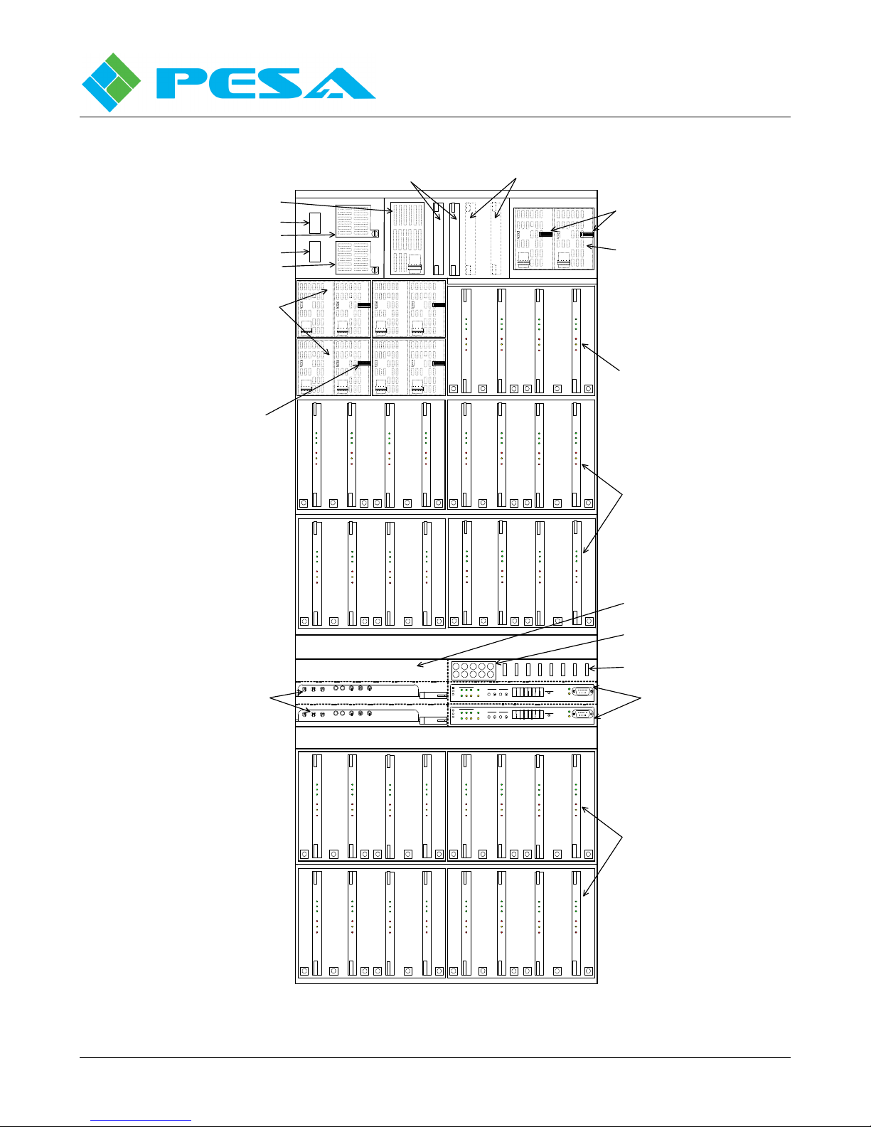
Using the 864 XR frame and the Cheetah 144X144 Matrix CCA a routing switcher with the capacity of
up to 864 inputs and 864 outputs can be configured in a single 41 rack unit (RU) frame. Table 2-1
indicates the maximum number of each core component type that can be installed in the 864XR frame.
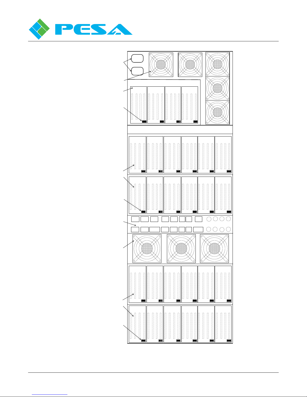
Figure 2-1 is a front view of the chassis layout with the access door open. Figure 2-2 is a rear view of
the 864XR frame.
Table 2-1 Cheetah Series Active Components Matrix
C
ORE COMPONENT MAXIMUM QUANTITIES FOR THE
Input Buffer
CCA 1
Matrix
CCA 1
Output Combiner
54 36 54 2 2 8
1
Indicated quantities are maximum number of cards each frame can support. Quantities of each CCA type will vary by
matrix configuration.
Proprietary Information of PESA 2-1
CCA 1
Matrix Frame
Controller CCA
864XR C
HASSIS FRAME
System Controller
CCA
Power Supply
Module
Page 8
C
HEETAH
864XR V
IDEO MATRIX SWITCHER
Publication 81-9059-0595-0, Rev. C
October 2010
Power Filter Module
Power Breake r 1
Rectifier Module 1
Power Breake r 2
Rectifier Module 2
Power Supply Modules (8)
and Power Supply
Backplanes (4)
(Power Supply Modules
Shown In Phantom, To Allow
View Of 8-Position DIP
Switch Located On Each
Power Supply Backplane)
8-Position DIP Switch
System Controller CCA
One or Two (For Redundancy)
Fan Controller CCA (2)
PWR OK
PWR OK
PWR OK
ALERT
ALERT
28V
28V
GND
GND
PS600
PS600
PWR OK
PWR OK
ALERT
ALERT
28V
28V
GND
GND
PS600
PS600
Matrix
Matrix
+28 V
+28 V
+2. 5 V
+2. 5 V
+1. 2 V
+1. 2 V
CTRL
CTRL
ERR
ERR
IN
IN
USE
USE
FAN
FAN
ERR
ERR
S1 S2 S3 S4 S5 S 6
Matrix
Matrix
+28 V
+28 V
+2. 5 V
+2. 5 V
+1. 2 V
+1. 2 V
CTRL
CTRL
ERR
ERR
IN
IN
USE
USE
FAN
FAN
ERR
ERR
S1 S2 S3 S4 S5 S 6
ACTIVE
STANDBY
RUN ACTIVE
GND +5V + BA TTER Y
GND +5V + BA TTER Y
BATTERY RE SET MODE
ACTIVE
STANDBY
RUN ACTIVE
BATTERY RE SET MODE
PWR OK
ALERT
ALERT
28V
28V
GND
GND
PS600
PS600
PWR OK
PWR OK
ALERT
ALERT
28V
28V
GND
GND
PS600
PS600
Matrix
Matrix
+28 V
+28 V
+2. 5 V
+2. 5 V
+1. 2 V
+1. 2 V
CTRL
CTRL
ERR
ERR
IN
IN
USE
USE
FAN
FAN
ERR
ERR
Matrix
Matrix
+28 V
+28 V
+2. 5 V
+2.5 V
+1. 2 V
+1.2 V
CTRL
CTRL
ERR
ERR
IN
IN
USE
USE
FAN
FAN
ERR
ERR
Card Slots Not Populated
(For Future Use)
PWR OK
PWR OK
ALERT
ALERT
28V
28V
GND
GND
PS600
PS600
Matrix
Matrix
+28 V
+28 V
+2.5 V
+2. 5 V
+1.2 V
+1. 2 V
CTRL
CTRL
ERR
ERR
IN
IN
USE
USE
FAN
FAN
ERR
ERR
Matrix
Matrix
+28 V
+28 V
+2. 5 V
+2. 5 V
+1. 2 V
+1. 2 V
CTRL
CTRL
ERR
ERR
IN
IN
USE
USE
FAN
FAN
ERR
ERR
S1 S2 S3 S4 S5 S6
Matrix
Matrix
+28 V
+28 V
+2.5 V
+2. 5 V
+1.2 V
+1. 2 V
CTRL
CTRL
ERR
ERR
IN
IN
USE
USE
FAN
FAN
ERR
ERR
Matrix
Matrix
+28 V
+28 V
+2. 5 V
+2. 5 V
+1. 2 V
+1. 2 V
CTRL
CTRL
ERR
ERR
IN
IN
USE
USE
FAN
FAN
ERR
ERR
S1 S2 S3 S4 S5 S6
Matrix
Matrix
+28 V
+28 V
+2. 5 V
+2. 5 V
+1. 2 V
+1. 2 V
CTRL
CTRL
ERR
ERR
IN
IN
USE
USE
FAN
FAN
ERR
ERR
Matrix
Matrix
+28 V
+28 V
+2. 5 V
+2. 5 V
+1. 2 V
+1. 2 V
CTRL
CTRL
ERR
ERR
IN
IN
USE
USE
FAN
FAN
ERR
ERR
S1 S2 S3 S4 S5 S 6
+28
+5
+3
+28
+5
+3
COMMUNICA TIO NS
RX RX LNK VT2
TXPRC
TX422 A CTNET
COMMUNICA TIO NS
RX RX LNK VT2
TXPRC
TX422 A CTNET
VT1
VT1
RESETACTIVE
RESETACTIVE
CONTR OL S TATU S
8 8 8 8 8 8 8 8
MATRIX FRA ME CO NT RO LLER
CONTR OL S TATU S
8 8 8 8 8 8 8 8
MATRIX FRA ME CO NT RO LLER
RX
SCROLL
TX
RX
SCROLL
TX
8-Position DIP Switch (2)
Power Supply Modules (2)
and Power Supply
Backplane (1)
(Power Supply Modules
Shown In Phantom, To Allow
View Of 8-Position DIP
Switch Located On Each
Power Supply Backplane)
144X144 Matrix CCAs (4) and
Matrix Backplanes (1)
(Matrix CCAs Shown Smaller
Than Actual Size To Allow View
Of Rotary Switches, S1 Thru S6,
Located On Matrix Backplane)
144X144 Matrix CCAs (16) and
Matrix Backplanes (4)
(Matrix CCAs Shown Smaller
Than Actual Size To Allow
View Of Rotary Switches, S1
Thru S6, Located On Each
Matrix Backplane)
Card Slot Not Populated
(For Future Use)
Rotary Switches (10) For Chassis
Strobe Configuration
Fuses (Blade Type)
Frame Controller CCA
One or Two (For Redundancy)
Proprietary Information of PESA 2-2
Matrix
Matrix
Matrix
+28 V
+2. 5 V
+1. 2 V
CTRL
ERR
IN
USE
FAN
ERR
Matrix
+28 V
+28 V
+2. 5 V
+2.5 V
+1. 2 V
+1.2 V
CTRL
CTRL
ERR
ERR
IN
IN
USE
USE
FAN
FAN
ERR
ERR
S1 S2 S3 S4 S5 S 6
Matrix
Matrix
+28 V
+2. 5 V
+1. 2 V
CTRL
ERR
IN
USE
FAN
ERR
Matrix
+28 V
+28 V
+2. 5 V
+2.5 V
+1. 2 V
+1.2 V
CTRL
CTRL
ERR
ERR
IN
IN
USE
USE
FAN
FAN
ERR
ERR
S1 S2 S3 S4 S5 S 6
Matrix
Matrix
+28 V
+2. 5 V
+1. 2 V
CTRL
ERR
IN
USE
FAN
ERR
+28 V
+28 V
+2.5 V
+2. 5 V
+1.2 V
+1. 2 V
CTRL
CTRL
ERR
ERR
IN
IN
USE
USE
FAN
FAN
ERR
ERR
S1 S2 S3 S4 S5 S6
Matrix
+28 V
+2. 5 V
+1. 2 V
CTRL
ERR
IN
USE
FAN
ERR
+28 V
+28 V
+2.5 V
+2. 5 V
+1.2 V
+1. 2 V
CTRL
CTRL
ERR
ERR
IN
IN
USE
USE
FAN
FAN
ERR
ERR
Matrix
Matrix
S1 S2 S3 S4 S5 S6
Matrix
+28 V
+2. 5 V
+1. 2 V
CTRL
ERR
IN
USE
FAN
ERR
Matrix
+28 V
+2. 5 V
+1. 2 V
CTRL
ERR
IN
USE
FAN
ERR
Figure 2-1 - 864XR Chasssis – Front View
Matrix
+28 V
+2. 5 V
+1. 2 V
CTRL
ERR
IN
USE
FAN
ERR
144X144 Matrix CCAs (16) and
Matrix Backplanes (4)
(Matrix CCAs Shown Smaller
Than Actual Size To Allow
Matrix
+28 V
+2. 5 V
+1. 2 V
CTRL
ERR
IN
USE
FAN
ERR
View Of Rotary Switches, S1
Thru S6, Located On Each
Matrix Backplane)
Page 9
C
HEETAH
864XR V
IDEO MATRIX SWITCHER
Publication 81-9059-0595-0, Rev. C
October 2010
PWR
Primary Power
Input Cables
Chassis Cooling
Fans
I/O CCAs (16) and
I/O Backplanes (4)
8-Position
DIP Switch
1
PWR
2
INPUT/OUTPU T CARD SLOT NUM BER
4 3 2 116 15 14 13 12 11 10 9 8 7 6 5
I/O CCAs (48) and
I/O Backplanes (12)
8-Position
DIP Switch
System Connectors
Panel
Chassis Cooling
Fans
40 39 38 37
1
64 63 62 61
1
COM1
COM4
8
8
8
RCP1 RCP2
RCP3 RCP4
1
1
1
8
8
8
NET
NET NET
1
8
8
COM3
PRC
1
8
INPUT/OUT PUT CARD SLOT NU MBER
36 35 34 33 32 31 30 29 28 27 26 25
1
INPUT/OUT PUT CARD SLOT NU MBER
60 59 58 57 56 55 54 53 52 51 50 49
1
Alarm AlarmCOM2
CONTROL INPU T / OUTPUT CONNECTORS
PRC Loop
1
8
171824 23 22 21 20 19
Mon1
Mon3
Mon2
Mon4
81
414248 47 46 45 44 43
81
181
8
181
8
NET
REF1 REF2
AUX F.C.
I/O CCAs (48) and
I/O Backplanes (12)
Proprietary Information of PESA 2-3
INPUT/OUT PUT CARD SLOT NU MBER
INPUT/OUT PUT CARD SLOT NU MBER
108 107106105 104 103102 101 100 99 98 97
8-Position
DIP Switch
112 111 110109
Figure 2-2 - 864XR Chassis – Rear View
656672 71 70 69 68 6788 87 86 85 84 83 82 81 80 79 78 77 76 75 74 73
8181818181 81
89
9096 95 94 93 92 91
8181818181 81
Page 10

C
HEETAH
864XR V
Publication 81-9059-0595-0, Rev. C
IDEO MATRIX SWITCHER
October 2010
2.2 R
The 864XR Frame is configured using combinations of the following Core System Components:
Input Circuit Card Assembly
Matrix Circuit Card Assembly
Output Circuit Card Assembly
Power Supply Module
Control System (System Controller CCA and Frame Controller CCA)
Each core component is identified and a very brief look at the function of each is provided in the
following paragraphs.
2.2.1 I
As the name implies, the Input Circuit Card Assembly (CCA), often referred to simply as the input card,
is the entry point for video signals into the routing switcher matrix. Each input card accepts up to 16
video input signals from various sources. There are six input card variations in the Cheetah Series
product line, to accommodate different input signal types.
Each input card, regardless of signal type, contains the cable equalization circuitry, buffer amplifiers
and signal drivers used to condition the incoming signal prior to entering the switching matrix. Each
input card also contains circuitry to monitor the status of the input channels, power rails and other
operational functions.
EVIEW OF CORE SYSTEM COMPONENTS
NPUT CIRCUIT CARD ASSEMBLY
Input cards are physically attached to the rear panel of the chassis frame and provide the input
connectors for attaching signals to the switcher. Each card is equipped with two status LEDs on the edge
of the assembly close to the bottom input connectors. The user can very quickly perform a visual
assessment of the status of the input cards by observing the state of the LEDs.
2.2.2 M
Each Matrix Card is where the actual crosspoint switching function takes place. In all Cheetah
variations, the matrix cards are installed inside the chassis frame and are accessible by opening the front
access door. Each card is equipped with LEDs on the assembly edge so that the user can quickly assess
the status of each matrix card in the system with a visual inspection.
2.2.3 O
The Output Card is the exit point for video signals leaving the routing switcher and each card provides
up to 16 video output channels. There are seven output card variations to accommodate different signal
output types.
Each output card contains the necessary channel combiner circuitry, buffer amplifiers, re-clocking
circuitry and driver amplifiers to generate the signal output for each channel. Voltage comparators
monitor the status of the power rails. On-board programmed logic circuitry interprets data from the
comparators along with data relevant to the status of the output channels and other card operational
functions to provide a real-time status monitor as to the health of each output card.
Output cards are physically attached to the rear panel of the chassis frame and provide the connectors
for accessing the signal outputs from the switcher. Each card is equipped with two status LEDs on the
edge of the assembly close to the bottom connectors. The user can very quickly perform a visual
assessment of the status of the output cards by observing the state of the LEDs.
ATRIX CIRCUIT CARD ASSEMBLY
UTPUT CIRCUIT CARD ASSEMBLY
Proprietary Information of PESA 2-4
Page 11

C
HEETAH
864XR V
Publication 81-9059-0595-0, Rev. C
IDEO MATRIX SWITCHER
October 2010
2.2.4 P
Cheetah video routing switchers use common 600 Watt power supply modules that provide a fully
regulated source of +28 VDC @ 22A for powering system components. The number of power supply
modules used in a frame is dependent on several factors including the number of input, matrix and
output cards required for system capacity and whether or not power redundancy is desired. Up to 8
Power Supply Modules may be installed in the 864XR Frame.
All of the power supply modules are physically and electrically identical. Each module is “hotswappable” for easy removal and replacement without any disruption of switcher outputs. Circuitry
internal to the power supply continuously monitors the operational parameters, output voltage and
current level and the module operating temperature. Three LED display devices on the front panel of
each module allow the user to quickly perform a visual assessment of the status of each supply module
by observing the state of the LEDs.
2.2.5 C
Every switcher configuration requires a Control System. In the Cheetah family there are two core
components of the control system that reside within the chassis frame: the System Controller Card and
the Frame Controller Card.
The System Controller Card resides in the matrix switcher frame, however the term System Controller
refers collectively to the System Controller CCA and its associated board-resident firmware and a
software application that runs on a Microsoft Windows based PC platform. In the Cheetah product line
there are two variations of System Controllers: the 3500PRO and the PERC2000. Regardless of which
control system is used (3500 or PERC), at least one system controller card must be installed in the
chassis frame. Each chassis frame can support up to two system controller cards although only one
controller card is required. A second system controller card may be installed for redundancy capability.
OWER SUPPLY MODULE
ONTROL SYSTEM
The Frame Controller Card also resides in the matrix switcher frame. Just as with the system controller
card, each chassis frame can support up to two frame controller cards, although only one is required. A
second frame controller card may be installed for redundancy capability.
Consider the System Controller to be the master overseer of the entire system. The system controller
card communicates bi-directionally with the frame controller circuitry. Think of the Frame Controller
as a slave that is subservient to its master – the System Controller. The Frame Controller circuitry
orchestrates all system switching commands and all other control functions for the entire switcher
frame. It is the job of the System Controller to keep the entire system running as it is programmed to
do. The System Controller provides programming functions and interface functions to various types of
control panels that may be used by facility operators to control operations of the entire switching
system. Also, the system may be operated from a Windows based PC interfaced to the system
controller and running the controller software application.
2.2.6 B
Note in Figure 2-1 that there are two power supply modules residing on each power supply backplane
along with an 8-position DIP switch; and four matrix cards residing on each matrix backplane along
with six rotary switches (S1 thru S6). In addition to the switches on the backplanes, also note the ten
rotary switches used for chassis strobe configuration.
Figure 2-2 illustrates the rear panel of the chassis frame where the input and output cards are installed.
Note in this figure that up to four input or output cards may reside on each I/O Backplane and that each
backplane contains an 8-position DIP switch.
ACKPLANES
Proprietary Information of PESA 2-5
Page 12

C
HEETAH
864XR V
Publication 81-9059-0595-0, Rev. C
IDEO MATRIX SWITCHER
October 2010
The DIP switches and rotary switches on the various backplanes and in the chassis frame are factory set
to assign operational parameters to the system components. The switch settings assign such things as
what channel numbers a bank of input or output cards will service, frame type, number of cooling fans,
etc. Although the switches are set at the factory for every system, a guide to the proper settings for each
switch peculiar to the 864XR Frame is included in Chapter 5 of this manual. This scheme of assigning
identification to the backplane and interface ports allows full interchangeability between like CCAs in
the system.
In every frame variation the input cards and the output cards are loaded through the rear panel card
chassis into mating connectors located on an I/O backplane. Each card chassis is configured using I/O
backplanes with four cards installed to each. All slots may or may not be used in a particular system
dependent on the number of input and output channels and whether or not the output cards are fitted
with option cards. When option cards are used, each output card will occupy two slots in the card
chassis. In a typical Cheetah system, the input cards and output cards will be co-resident in the card
chassis. Be aware that although input cards and output cards can be co-resident in the card chassis, they
CAN NOT be co-resident on the same backplane. Each I/O backplane in the chassis is designated as
either an input or an output backplane.
2.3 864 XR F
Physical
RUs....................................................................................................................................... 41
Height .............................................................................................................................71.75"
Width ...................................................................................................................................19"
Depth....................................................................................................................................23"
Weight...........................................................................................625 lbs. (281.25 kg) nominal
............................................................................ (May weigh less depending on configuration)
Supply Power Requirements
Operating voltage ..................................................................................95-240 VAC, 47-63 Hz
Power consumption .................................................................... 2500W Nominal, 6000W Max
Power Supplies
DC Input (from the source rectification filter/breaker assy.) .......................95 VDC to 240 VDC
DC Output.................................................................................................................... 28 VDC
Maximum Output Watts ............................................................................................ 600 Watts
Digital Electrical Signals for Inputs
Standards:.................................................. High Definition video conforming to SMPTE 292M
......................................................................Serial Digital video conforming to SMPTE 259M
Connector Type: .......................................................................................................75Ω BNC
Impedance: ..........................................................................................................75Ω nominal
Return Loss:...................................................................... HD >15 dB from 5MHz to 1.5 GHz
......................................................................................... SD >15 dB from 5 MHz to 540 MHz
Cable Equalization: ............................................HD Automatic up to 100 meters, Belden 8281
...........................................................................SD Automatic up to 300 meters, Belden 8281
RAME SPECIFICATIONS
Proprietary Information of PESA 2-6
Continued
Page 13

C
HEETAH
864XR V
Publication 81-9059-0595-0, Rev. C
IDEO MATRIX SWITCHER
October 2010
864 XR Specifications (cont.)
Electrical Signals for Outputs
Connector Type: ...................................................................................75Ω BNC (output card)
...................................................................................................... 75Ω BNC (dual output card)
Signal Level: ..............................................................................................800 mV p-p, ±10%
Signal Polarity: ..........................................................Non-inverting with respect to input ports
Impedance: ...........................................................................................................75Ω nominal
Return Loss:....................................................................... HD >15 dB from 5MHz to 1.5 GHz
.......................................................................................... SD >15 dB from 5MHz to 540 MHz
Optical Signals (Fiber Optics) for Inputs (Receivers)
Connector Type: .............................................................. SFP modules w/LC-type (fiber card)
Data Rates:...........................................................................................1.0 Mbps to 1.485 Gbps
Optical Input Wavelength...........................................................Single Mode, 1200 to 1600 nm
Input Power............................................................................................... -20 dBm (minimum)
Optical Signals (Fiber Optics) for Outputs (Transmitters)
Connector Type.................................................................SFP modules w/LC-type (fiber card)
Data Rates:..............................................................................................1 Mbps to 1.485 Gbps
Optical Output Wavelength....................................................... Single Mode, 1310 nm, ±20 nm
Output Power ...............................................................................................................-11 dBm
Optical Loss Budget
10,000 km (minimum), Single Mode fiber w/2 optical couplings...................... 9 dB (minimum)
Signal Operational Specifications
Polarity: ............................................................................................... All paths non-inverting
Re-clocking SD: ...................................Automatic selection of 143 Mb/s, 177 Mb/s, 270Mb/s,
...................................................................................................................360 Mb/s, 540 Mb/s
Re-clocking HD: ................. Automatic selection of 143 Mb/s, 177 Mb/s, 270 Mb/s, 360 Mb/s,
.............................................................................................................. 540 Mb/s and 1.5 GB/s
Reference (Sync) Inputs
No. of Inputs: ............................................................................................................ 2 standard
Connector: .................................................................................................................75Ω BNC
Return Loss: ............................................................................... > 40 dB, 100 KHz to 30 MHz
Signal Formats: ..................................................... NTSC, PAL (Black Burst), or HD Tri-Level
....................................................................................... Sync per SMPTE 274, SMPTE 276 M
Signal Level: .......................................................................................Nominal 1.0 V p-p ±6dB
Continued
Proprietary Information of PESA 2-7
Page 14

C
HEETAH
864XR V
Publication 81-9059-0595-0, Rev. C
IDEO MATRIX SWITCHER
October 2010
864 XR Specifications (cont.)
DAC Card Specifications
Connector Type: .......................................................................................................75Ω BNC
Connection/Card: ................................................................................... 16 Individual Outputs
Conversion: ................................................................................10 bit Serial Digital to Analog
Over sampling:..................................................................................................................... 4X
Output:....................................................................................................................NTSC/PAL
Cooling
Internal cooling fans with auto sensing speed adjustments
Control
Panel Com:...........................................................................RS-485, 3 pin WECO, 4 per frame
Control Com:...................................................... RS-232 or PESA PRC for 3500 Series System
Connector Type:......................................................................................... 9 pin, D sub, female
Network Connector: ......................................................................RJ-45, Ethernet, 2 per frame
Environmental
Operating Temperature:.................................................................................................0-40 °C
Operating Humidity:.............................................................................10-90% non condensing
Standard Analog Video Input Characteristics
Level:....................................................................................1.0V P-P nominal, 2.0V P-P max.
............................................................................................. (Without obvious distortion)
Impedance:.........................................................................................75Ω internally terminated
Return Loss:..................................................................................................> 40 dB to 5 MHz
.....................................................................................................................> 15dB to 50 MHz
Coupling:.................................................................................................................Direct (DC)
Type:...........................................................................................................................Balanced
Connector:......................................................................................................................... BNC
Standard Analog Video Output Characteristics
Level:....................................................................................1.0V P-P nominal, 2.0V P-P max.
............................................................................................. (Without obvious distortion)
Impedance:.........................................................................................75Ω internally terminated
Return Loss:............................................................................................... > 40 dB to 5.0 MHz
.................................................................................................................... > 15 dB to 50 MHz
Coupling:.................................................................................................................Direct (DC)
DC on Out:................................................................................................................. <±30 mV
Connector:......................................................................................................................... BNC
Number:.....................................................................................................One (Two Optional)
Proprietary Information of PESA 2-8
Continued
Page 15

C
HEETAH
864XR V
Publication 81-9059-0595-0, Rev. C
IDEO MATRIX SWITCHER
October 2010
864 XR Specifications (cont.)
Standard Analog Video Gain Characteristics
Gain: ................................................................................................................................ Unity
Gain Stability: .................................................................................................... <±0.1 dB max.
Gain Adjust Range: .......................................................................................................±0.5 dB
Standard Analog Video Linear Distortion
Frequency Response:................................................................................... ±0.1 dB to 10 MHz
.................................................................................................................... ±0.5 dB to 35 MHz
..................................................................................................................... -3.0 dB @50 MHz
Vertical Tilt:.................................................................................. 0.25% (50 Hz Square Wave)
Horizontal Tilt:................................................................................................................ 0.25%
Low Frequency:................................................................ +0.2% /ms max with 10% Overshoot
.......................................................................................................(10-90% or 90-10% change)
Standard Analog Video Pulse and Bar Responses
Factor (2T) Bar Slope:................................................................................................... 0.2% K
Pulse/Bar Ratio:............................................................................................................. 0.2% K
Pulse Sharp:................................................................................................................... 0.2% K
Standard Analog Video Chrominance/Luminance
Gain Inequity:......................................................................................................... ±1.0% max.
Delay Inequity:...............................................................................................................±1.0 ns
Standard Analog Video Non-Linear Distortions
Note: All tests: 10 to 90% @ 3.58MHz or 12.5 to 87.5% @ 4.43Mhz.
Differential Gain:........................................................................................ 0.25% @ 4.43 MHz
Envelope Delay:...............................................................................<2.0ns, 50MHz to 85 MHz
Differential Phase:........................................................................................0.25° @ 4.43 MHz
Line Time Non-Linearity:..................................................................................................0.2%
Transient Gain:......................................................... 1.0% (Luminance, Chrominance, or Sync)
Video o Video Crosstalk:..........................≤ -60 dB to 5.0 MHz (all Inputs and Outputs Hostile)
.................................................................................................................. ≤ -35 dB @ 35 MHz
Standard Analog Video Switching Characteristics
Switching Time:............................................................................................................≤ 1.0 µs
Switching Transient:................................................................................22 mV (30 IRE Units)
Differential Delay (any Input to any Output)........................................................ Approx. 8.5ns
........................................................................................................................11° @ 3.58 MHz
......................................................................................................................13.5° @4.43 MHz
Standard Analog Video Signal to Noise
Video Filter:.........................................................-70 dB RMS Noise to P-P Signal to 5.0 MHz
Proprietary Information of PESA 2-9
Continued
Page 16

C
HEETAH
864XR V
Publication 81-9059-0595-0, Rev. C
IDEO MATRIX SWITCHER
October 2010
864 XR Specifications (cont.)
High-Level Analog Video Input Characteristics
Level:..............................................................................................±5.0 V, Referred to Ground
Impedance:.........................................................................................75Ω internally terminated
Return Loss:............................................................................................... > 40 dB to 5.0 MHz
.................................................................................................................... > 15 dB to 50 MHz
Coupling:.................................................................................................................Direct (DC)
Type:...........................................................................................................................Balanced
Connector:......................................................................................................................... BNC
High-Level Analog Video Output Characteristics
Level:..............................................................................................±5.0 V, Referred to Ground
Impedance:.........................................................................................75Ω internally terminated
Return Loss:............................................................................................... > 40 dB to 5.0 MHz
.................................................................................................................... > 15 dB to 50 MHz
Coupling:.................................................................................................................Direct (DC)
DC on Out:................................................................................................................. <±50 mV
Connector:......................................................................................................................... BNC
Number:.....................................................................................................One (Two Optional)
High-Level Analog Video Gain Characteristics
Gain: ................................................................................................................................ Unity
Gain Stability: .............................................................................................................<±0.1 dB
Gain Adjust Range: .......................................................................................................±0.5 dB
High-Level Analog Video Linear Distortion
Frequency Response:................................................................................... ±0.1 dB to 10 MHz
.................................................................................................................... ±0.5 dB to 35 MHz
..................................................................................................................... -3.0 dB @50 MHz
Vertical Tilt:.................................................................................. 0.25% (50 Hz Square Wave)
Horizontal Tilt:................................................................................................................ 0.25%
Crosstalk: ............................................. <± -60 dB to 5.0 MHz (All Inputs and Outputs Hostile)
................................................................................................................ <± -35 dB @ 35 MHz
High-Level Analog Video Signal to Noise
Signal to Noise:.................................................. -70 dB, RMS Noise to P-P Signal to 5.0 MHZ
Proprietary Information of PESA 2-10
Page 17

C
HEETAH
864XR V
Publication 81-9059-0595-0, Rev. C
IDEO MATRIX SWITCHER
October 2010
All Cheetah video matrix switchers offer alarm support, switch confirmation, block checking, and
power-out-of-range indicators. Features include:
• Full feature control system using either standard PESA PRC Control or PESA Network Control
• Video and data signal from 3Mb/s to 1.5 GB/s
• Conforms to SMPTE 259M and 292M
• Input EQ to 300M SD, 100M HD
• Bypass mode for non-standard data signals
• Full redundant controllers available
• N+1 redundant internal DC power; full redundant AC power
• All modules are hot-swappable for on-air maintenance
Proprietary Information of PESA 2-11
Page 18
C
HEETAH
864XR V
Publication 81-9059-0595-0, Rev. C
IDEO MATRIX SWITCHER
October 2010
Chapter 3: Installation
3.1 U
3.2 G
NPACKING AND INSPECTION
This equipment contains electrostatic sensitive devices (ESD). Use a grounded
wrist strap, grounding mat, and/or comply with local established ESD
procedures when handling the internal circuit cards to prevent destruction
from electrostatic discharge.
Immediately upon receipt, inspect all shipping containers. Carefully unpack the equipment and
compare the parts received against the packing list. If any parts appear to be missing or damaged,
please contact PESA immediately.
ENERAL CHASSIS INSTALLATION OVERVIEW
The physical size of each Cheetah Series Switcher chassis is determined by the chassis input/output
capabilities. If specified when ordered, each Cheetah Switcher will be configured for the intended
system at the factory. Before attempting to install any frame, matrix card, controller card, or power
supply, carefully read and understand this section.
All Cheetah Switchers contain electrostatic sensitive devices (ESD). Care
should be used when it is necessary to handle the internal circuit cards. It is
recommended that a grounded wrist strap and grounding mat be used before
attempting any equipment installations.
3.3 C
HOOSING A LOCATION
For local electrical compliance, this equipment should be located near the
primary power disconnect/breaker so that the AC supply disconnect is
easily accessible.
This equipment is designed for installation in a standard 19" equipment rack located in an environment
conforming to the specifications for each chassis. Locate each unit as close as possible to its associated
equipment to minimize cable runs.
Consider the connection from this equipment to the supply circuit, and the effect that possible
overloading can have on overcurrent protection circuits and supply wiring. Refer to nameplate ratings
when addressing this concern.
Proprietary Information of PESA 3-1
Page 19

ully loaded 864XR chassis frame exceeds 650 lbs nominal.
airflow around these fans. Replace all service panels and blank filler plates.
C
HEETAH
864XR V
Publication 81-9059-0595-0, Rev. C
IDEO MATRIX SWITCHER
October 2010
3.4 M
OUNTING THE
864XR C
HASSIS IN AN EQUIPMENT RACK
The weight of a f
Installation or removal of this equipment requires at least four persons in
order to avoid possible personal injury or equipment damage. Install this
equipment in such a manner as to avoid any tipping hazard from uneven
loading of the equipment.
Make sure that all power is disconnected and the chassis breakers are in the
OFF position before installing the specific frame into the rack.
Fans mounted on this equipment provide forced-air cooling. Do not block
Keep the front access door closed during normal operation.
This equipment is designed for installation in a standard 19" equipment rack. Provide sufficient space
behind the equipment racks to allow for control, signal, and power cables. Use all chassis mounting
holes, and tighten mounting hardware securely by using the rack equipment manufacturer’s suggested
torque settings.
This unit is extremely heavy. Maneuvering and installation of this unit
requires caution, planning, and adequate resources in order to prevent injury
to personnel and/or damage to the equipment. It is strongly suggested to
implement as many persons, jacks, blocks, etc., as possible to eliminate any
unsafe condition that could result during the chassis mounting phase of
installation.
Proprietary Information of PESA 3-2
Page 20

C
HEETAH
864XR V
Publication 81-9059-0595-0, Rev. C
IDEO MATRIX SWITCHER
October 2010
3.4.1 C
HEETAH CHASSIS MOUNTING PROCEDURE
The following steps should be performed to reduce the weight of the system thus making it slightly
easier to maneuver.
1. Have the wooden shipping crate standing upright before opening the crate.
2. Remove all the lag bolts from the top and sides of the wooden crate.
3. Using ESD precautions, remove the power supply modules from the top of the unit.
Prior to performing the next sequence, careful measurements should be
completed to insure the proper location and alignment of equipment rack’s
screw holes to the Cheetah chassis.
4. Using a pallet jack or similar equipment, align and place the 864XR Chassis as close as possible
to the equipment rack opening where it will be installed.
5. Using as much manpower as necessary, CAREFULLY move the 864XR chassis from the
wooden pallet to the equipment rack and slide the chassis into position in the rack.
6. With the chassis installed in the equipment rack, install the rack screws in the chassis ensuring
that the unit is firmly and adequately secured to the equipment rack.
Proprietary Information of PESA 3-3
Page 21

C
HEETAH
864XR V
Publication 81-9059-0595-0, Rev. C
IDEO MATRIX SWITCHER
October 2010
3.5 C
ONNECT EQUIPMENT CABLES
Once the Cheetah Video Matrix Frame is installed in the equipment rack, the associated system
connections can be completed. The order of completion of installation steps is not critical, however,
DO NOT apply power to a frame until all of the video signal, sync and control cables have been
installed and their connections verified for proper placement and accuracy. Use the following guide to
insure that all connections are made properly and that power, system interconnect and video signal
cables are correctly installed.
Use the following guidelines when connecting equipment cables:
Install the equipment in the rack before connecting cables.
Relieve strain on all cables to prevent connector separation.
To the greatest extent possible, separate control, signal, and power cables to minimize any possible
crosstalk or interference.
Use as many cable ties as necessary to secure cables to the rack, as shown in Figure 3-1. This will
provide cable strain relief and help route cables away from hazardous areas.
Route cables away from physical traffic areas to avoid creating a safety hazard (trip or shock).
3.6 C
HEETAH CHASSIS SUPPLY POWER CONNECTIONS
The 864XR chassis frame has two AC (or DC) primary power input cables. As shown in Figure 3-2,
each AC power input is rectified and routed to the filter assembly.
Proprietary Information of PESA 3-4
Figure 3-1 - Cables Attached To Supports
(US M
ODELS
)
Page 22

across both AC power inputs must not exceed 250VAC at any time.
C
HEETAH
864XR V
IDEO MATRIX SWITCHER
Publication 81-9059-0595-0, Rev. C
October 2010
D
Perform voltage measurements A thru D, between the
C
points indicated by arrows using an AC Voltmeter. ALL
B
measurements must be less than, or equal to, 250VAC.
A
PRIMARY
POWER
INPUT 1
(PIGTAI L)
PRIMARY
POWER
INPUT 2
(PIGTAI L)
RECTIFIER MODULE 1
CHASSIS
FRAME
AC BREA KER 1
RECTIFIER MODULE 2
CHASSIS
FRAME
AC BREA KER 2
POWER FILTER MODULE
V DC OUT TO
POWER SUPPLY
MODULES
Figure 3-2 - Power Supply Configuration (US Models)
WARNING: The maximum applied voltage to either of the AC power
inputs must not exceed 250VAC. In addition, the maximum applied voltage
Whenever two phases of a three-phase power source are applied using
different phases on each power input, the voltage between the phases must
not exceed 250VAC. Failure to heed this warning will result in serious
equipment damage.
Figure 3-3 depicts a typical two-phase and three-phase AC line-phasing scenario. Note that in the threephase line voltage, each voltage phase is 120 degrees out of phase with the other two voltage phases.
Proprietary Information of PESA 3-5
Page 23

has an interface solution to address your needs.
protection devices in the supply circuitry of any Cheetah series systems.
C
HEETAH
864XR V
IDEO MATRIX SWITCHER
Publication 81-9059-0595-0, Rev. C
October 2010
A B
250VAC
MAX
A C
250VAC
MAX
B C
250VAC
MAX
A B C
AC Power IN
3 Phase; 120 degrees apart
MAX 250VAC between any two phases
Figure 3-3 - Phase Relationships
Additionally, systems with one AC power input supplied from a normal, “in-house” AC line
and the other AC power input supplied from an external generator must insure that, regardless
of the voltage-phase relationship between the external generator and the “in house” AC line,
the maximum applied voltage between the two AC power inputs does not exceed 250VAC.
3.6.1 864XR F
If your application requires two independent phases, which exceed the
250VAC maximum, PESA
Please contact your PESA dealer or Area Sales Manager.
Additionally, it is NOT recommended to use single-phase GFCI circuit
Due to unbalanced currents in the neutral circuitry, single-phase GFCI
devices will typically trip. However (if employed), a three-phase GFCI
breaker will not trip except under fault conditions.
RAME PRIMARY POWER
Make sure that all power is disconnected and the chassis breakers are in the
OFF position before completing the specific power connections.
To prevent damage to the equipment:
•
Read all instructions for proper input voltage ranges.
•
Use only a power circuit with the specified current capacity.
•
Follow static prevention precautions prior to handling equipment.
Proprietary Information of PESA 3-6
Page 24

Green/Yellow
3.6.1.1 Power Cabling and Circuit Breakers
The 864XR chassis is supplied with a power cabling assembly (see Figure 3-4) that meets and/or
exceeds the requirements for dedicated input service lines rated for 200-240VAC at 30 amps
minimum. Two main circuit breakers are mounted on the front side of the 864XR frame in the
upper left corner. Table 3-1 describes the power connections for the associated pigtail cabling
conductors.
Table 3-1 - Pigtail Cabling Conductor Power Connections
Color Code 200-240V
Green/Yellow Stripe Safety Ground
Blue AC Line
Brown AC Line
Stripe
C
HEETAH
864XR V
Publication 81-9059-0595-0, Rev. C
IDEO MATRIX SWITCHER
October 2010
Blue
Brown
Figure 3-4 - Pigtail Cabling Conductors
3.6.1.2 External AC Power Requirements
Each 864XR chassis is supplied with pigtail cabling (see Figure 3-4 and refer to Tables 3-1) rated for
200-240VAC at 30 amps. The router is to be connected only to a dedicated service line capable of
providing the power source specified in Table 3-2.
Table 3-2 - AC Power Filter Assembly
Minimum Amps
AC Power Cable
Required
200-240V Attached Power Cable Pigtails 30A Service
Service Drops
1-Standard
1-Redundant
3.7 I
NTERNATIONAL POWER REQUIREMENTS FOR CHEETAH CHASSIS
All 864XR frames have two AC (or DC) main power feeds. For international use only, these power
feeds are isolated from each another through a special wiring configuration that is completed at the
factory (Figure 3-5).
Proprietary Information of PESA 3-7
Page 25

the other AC power input must not exceed 380VAC nominal at any time.
C
HEETAH
864XR V
IDEO MATRIX SWITCHER
Publication 81-9059-0595-0, Rev. C
October 2010
AC
AC
2
Filter
1
AC 1
Breaker
AC 2
Breaker
Bridge
Rectifier
Bridge
Rectifier
Output VDC
Filter
Output VDC
(-)
(+)
(-)
(+)
½ of
Cheetah’s
Power
Supply Bank
½ of
Cheetah’s
Power
Supply Bank
Figure 3-5 - International Power Supplies Configuration
In each Cheetah assembly, the entire power supply backplane is divided in half and each half is powered
and isolated separately. The following apply to the Cheetah international supply power inputs:
•
Two banks of power supplies are required in each Cheetah switcher assembly and each bank
must be capable of supplying ALL of the power that is required by the specific Cheetah
switcher.
•
Both banks must be powered under normal conditions.
•
Loss of either AC supply power feed is considered a fault condition.
•
When experiencing a loss of one AC supply power feed (fault condition), the remaining
supplies will typically operate at 100% of their rated load. An increase in chassis operating
temperature is normal as the supplies are typically changing from approximately 50% load to
approximately 100% of their rated load.
WARNING: The maximum applied voltage between any leg of either of
the isolated AC power inputs must not exceed 250VAC. In addition, the
maximum applied voltage between any leg of one AC input and any leg of
That is, whenever two phases of a three-phase power source is applied using
different phases on each power input, the voltage between the phases must
not exceed 380VAC nominal. Failure to heed this warning will result in
serious equipment damage.
Proprietary Information of PESA 3-8
Page 26

C
HEETAH
864XR V
Publication 81-9059-0595-0, Rev. C
IDEO MATRIX SWITCHER
October 2010
3.8 V
IDEO INPUT/OUTPUT CONNECTIONS
Once the rack frame is mounted and primary power connections have been completed, connecting the
video input and output signals is the next step. Figure 3-6 illustrates the entire rear panel of the router
and features a quick reference guide to the input and output connector configuration. Figures 3-7, 3-8
and 3-9 provide a closer and more detailed view of the rear panel input and output connectors divided
into sections from the top of the switcher to the bottom. Use these references when making video I/O
connections to the 864XR router.
PESA recommends that you make a layout plan and connection drawing to document I/O connections
to the router and follow this drawing when attaching video connectors to the input and output cards.
Retain this documentation in a safe place in the event that service to the router should ever be needed.
PESA also recommends that you label each video cable to identify its source or destination.
Proprietary Information of PESA 3-9
Page 27

C
HEETAH
864XR V
IDEO MATRIX SWITCHER
Publication 81-9059-0595-0, Rev. C
October 2010
CHEETAH 864XR FRAME - REAR VIEW
PWR
1
PWR
2
INPUT/OUTPUT CARD SLOT NUMBER
OUTPUT CHANNELS: 1 - 256
40 39 38 37
INPUT
1 - 64
64 63 62 61 60 59 58 57 56 55 54 53 52 51 50
INPUT/OUTPUT CARD SLOT NUMBER
35 34 33 32 31 30 29 28 27 26 25
OUTPUT CHANNELS 257 - 576
INPUT/OUTPUT CARD SLOT NUMBER
INPUT CHANNELS: 65 - 448
COM1
COM4
COM3
PRC
RCP1 RCP2
Alarm AlarmCOM2
CONTROL INPU T / OUTPUT CONNECTORS
PRC Loop
RCP3 RCP4
NET
NET NET
NET
128 7 6 5 4 316 15 14 13 12 11 10 9
2136
48 47 46 45 44 43 42 41
49
REF1 REF2
AUX F.C.
Mon1
Mon3
Input/Output Connector Channels By I/O Card Slot Number
Quick Reference Chart
INPUT CHANNELS
Input/Outpu t
Card Slot
Number
56
57
58
59
60
61
62
63
64
65
66
67
68
69
70
71
72
73
74
NOTE
Channels
305 - 320
321 - 336
337 - 352
353 - 368
369 - 384
385 - 400
401 - 416
417 - 432
433 - 448
449 - 464
465 - 480
481 - 496
497 - 512
513 - 528
529 - 544
545 - 560
561 – 576
577 – 592
593 - 608
Input
On Card
Input/Outp ut
Card Slot
Input Card Slots are i ndicated by BOLD outlines and
BOLD ITALICS text on the fi gure and in this char t.
Number
37
38
39
40
41
42
43
44
45
46
47
48
49
50
51
52
53
54
55
Input
Channels
On Card
1 - 16
17 -32
33 - 48
49 - 64
65 - 80
81 - 96
97 - 112
113 - 128
129 - 144
145 - 160
161 - 176
177 - 192
193 - 208
209 - 224
225 - 240
241 - 256
257 - 272
273 - 288
289 - 304
Input/Out put
Card Slot
171824 23 22 20 19
OUTPUT CHANNELS
Mon2
Mon4
Input/Outpu t
Card Slot
Number
1
2
3
4
5
6
7
8
9
10
11
12
13
14
15
16
17
18
19
Output
Channels
On Card
1 - 16
17 -32
33 - 48
49 - 64
65 - 80
81 - 96
97 - 112
113 - 128
129 - 144
145 - 160
161 - 176
177 - 192
193 - 208
209 - 224
225 - 240
241 – 256
257 - 272
273 - 288
289 - 304
Input/Ou tput
Card Slot
Number
20
21
22
23
24
25
26
27
28
29
30
31
32
33
34
35
36
93
94
Output
Channels
On Card
305 - 320
321 - 336
337 - 352
353 - 368
369 - 384
385 - 400
401 - 416
417 - 432
433 - 448
449 - 464
465 - 480
481 - 496
497 – 512
513 - 528
529 - 544
545 - 560
561 – 576
577 – 592
593 - 608
Input/O utput
Card Slot
Number
Number
75
76
77
78
79
80
81
82
83
84
85
86
87
88
89
90
91
92
95
96
97
98
99
100
101
102
103
104
105
106
107
108
109
110
111
112
Input
Channels
On Card
609 - 624
625 – 640
641 - 656
657 - 672
673 - 688
689 - 704
705 - 720
721 - 736
737 - 752
753 - 768
769 - 784
785 - 800
801 - 816
817 - 832
833 - 848
849 – 864
S1 – SPARE
S2 - SPARE
Output
Channels
On Card
609 - 624
625 – 640
641 - 656
657 - 672
673 - 688
689 - 704
705 - 720
721 - 736
737 - 752
753 - 768
769 - 784
785 - 800
801 - 816
817 - 832
833 - 848
849 – 864
S3 – SPA RE
S4 - SPA RE
BNC Connector Numbering Detail
Top Connector (Lowest Channel
INPUT/OUTPUT CARD SLOT NUMBER
7380 79 78 7788 87 86 85 84 83 82 81 7476 75
72 71 70 69 68 67 66 65
Number) On Connector Board
Channel 1, 17, 33, 49,….849
INPUT CHANNELS: 449 - 832
112 111 110 109
INPUT/OUTPUT CARD SLOT NUMBER
108 107 106 105104 103 102 101 100 99 98 97
OUTPUT CHANNELS: 577 - 864
INPUT
833 - 864
899096 95 94 93 92 91
Bottom Connector (Highest Channel
Number) On Connector Board
Channel 16, 32, 48, 64,….864
Figure 3-6 – 864XR Chassis – Rear View
Proprietary Information of PESA 3-10
Page 28

C
HEETAH
864XR V
IDEO MATRIX SWITCHER
Publication 81-9059-0595-0, Rev. C
October 2010
PWR
1
PWR
2
INPUT/OUTPUT CARD SLOT NUMBER
16 15 14 13 12 11 10 9 8 7 6 5 4 3 2
177
193
OUT
241
Thru
256
256
OUT
225
Thru
240
240
209225241
OUT
209
Thru
224
224
OUT
193
Thru
208
208
OUT
177
Thru
192
192
OUT
161
Thru
176
176
145161
OUT
145
Thru
160
160
129
OUT
129
Thru
144
144
113
OUT
113
Thru
128
128
OUT
97
Thru
112
112
8197
OUT
81
Thru
96
96
65
OUT
65
Thru
80
80
49
OUT
49
Thru
64
64
OUTPUT CHANNELS: 1 - 256
OUT
33
Thru
48
48
1733
OUT
17
Thru
32
32
1
OUT
Thru
16
16
1
1
Figure 3-7 - Channel Assignments – I/O Card Slots 1 - 16
Proprietary Information of PESA 3-11
Page 29

C
HEETAH
864XR V
IDEO MATRIX SWITCHER
Publication 81-9059-0595-0, Rev. C
October 2010
INPUT/OUTPUT CARD SLOT NUMBER
40 39 38 37 36 35 34 33 32 31 30 29 28 27 26 25
24
1
Thru
Thru
1733
IN
IN
IN
17
33
Thru
32
48
32
48
Thru
OUT
1
561
Thru
16
576
16
576
OUT
545
Thru
560
560
529545561
OUT
529
Thru
544
544
513
OUT
513
Thru
528
528
497
OUT
497
Thru
512
512
OUT
481
Thru
496
496
49
IN
49
64
64
465481
OUT
465
Thru
480
480
449
OUT
449
Thru
464
464
433
OUT
433
Thru
448
448
OUT
417
Thru
432
432
401417
OUT
401
Thru
416
416
24 23 22 21 20 19 18 17
321
OUT
353
Thru
368
368
337353
OUT
337
Thru
352
352
OUT
321
Thru
336
336
305
OUT
305
Thru
320
320
385
OUT
385
Thru
400
400
369
OUT
369
Thru
384
384
OUT
289
Thru
304
304
273289
OUT
273
Thru
288
288
257
OUT
257
Thru
272
272
INPUT
1 - 64
OUTPUT CHANNELS: 257 - 576
INPUT/OUTPUT CARD SLOT NUMBER
64 63 62 61 60 59 58 57 56 55 54 53 52 51 50 49 48 47 46 45 44 43 42 41
24
257
289
Thru
304
273289
IN
IN
273
Thru
288
288304320
257
Thru
272
272
241
IN
IN
241
Thru
256
256
225
Thru
240
240
209225
IN
IN
209
Thru
224
224
193
193
Thru
208
208
177
IN
177
Thru
192
192
IN
IN
161
Thru
176
176
145161
145
Thru
160
160
129
113
IN
IN
IN
IN
129
Thru
144
144
113
Thru
128
128
97
Thru
112
112
433
433
Thru
448
321
353
Thru
368
337353
IN
IN
337
Thru
352
352368384
321
Thru
336
336
305
IN
IN
305
Thru
320
385
401417
IN
IN
IN
417
Thru
432
401
Thru
416
416432448
385
Thru
400
400
369
IN
IN
369
Thru
384
INPUT CHANNELS: 65 - 448
Thru
65
8197
IN
IN
65
81
Thru
80
96
80
96
Figure 3-8 - Channel Assignments - I/O Card Slots 17 - 64
Proprietary Information of PESA 3-12
Page 30

C
HEETAH
864XR V
IDEO MATRIX SWITCHER
Publication 81-9059-0595-0, Rev. C
October 2010
INPUT/OUTPUT CARD SLOT NUMBER
88 87 86 85 84 83 82 81 80 79 78 77 76 75 74 73 72 71 70 69 68 67 66 65
24
449
481
Thru
496
465481
IN
IN
IN
465
Thru
480
480496512
449
Thru
464
464
817
817
Thru
832
577
609
Thru
624
593609
IN
IN
593
Thru
608
608624640
577
Thru
592
592
561
IN
561
Thru
576
IN
IN
545
Thru
560
529545
529
Thru
544
544560576
513
497
IN
IN
IN
513
Thru
528
528
497
Thru
512
641
673
Thru
688
657673689
IN
IN
657
Thru
672
672688
641
Thru
656
656
625
IN
IN
625
Thru
640
705
737
Thru
752
721737753
IN
IN
721
Thru
736
736752
705
Thru
720
720
IN
IN
689
Thru
704
704
769
IN
801
Thru
816
785
Thru
800
800816832
785801
IN
IN
769
Thru
784
784
IN
IN
753
Thru
768
768
INPUT CHANNELS: 449 - 832
INPUT/OUTPUT CARD SLOT NUMBER
112 111 110 109 108 107 106 105 104 103 102 101 100 99 98 97
24
833
S4
SPARE
S3
SPARE
849
OUT
849
Thru
864
864
OUT
833
Thru
848
848
817
OUT
817
Thru
832
OUT
801
Thru
816
785801
OUT
785
Thru
800
800816832
769
OUT
769
Thru
784
784
OUT
753
Thru
768
OUT
737
Thru
752
721737753
OUT
721
Thru
736
736752768
705
OUT
Thru
720
705
720
Thru
704
Thru
688
OUT
OUT
673
689
OUTPUT CHANNELS: 577 - 864
657673689
OUT
657
Thru
672
672688704
96 95 94 93 92 91 90 89
577
OUT
609
Thru
624
593609625
OUT
593
Thru
608
608624640
OUT
577
Thru
592
592
S2
SPARE
641
OUT
641
Thru
656
656
OUT
625
Thru
640
833 - 864
S1
SPARE
INPUT
849
849
Thru
864
864
833
IN
IN
833
Thru
848
848
Figure 3-9 - Channel Assignments - I/O Card Slots 65 - 112
Proprietary Information of PESA 3-13
Page 31

C
HEETAH
864XR V
IDEO MATRIX SWITCHER
Publication 81-9059-0595-0, Rev. C
October 2010
3.9 R
EAR PANEL SYSTEM CONNECTIONS
When the video I/O connections are completed, connecting the various system control and operational
signals is the next step. The following paragraphs identify and define the operational and control
connection points. Follow the information contained in each paragraph carefully when making control
and system I/O connections to the 864XR router.
PESA recommends that you make a layout plan and connection drawing to document system
connections to the router and follow this drawing when attaching cabling to the rear panel connectors
of the router. Retain this documentation in a safe place in the event that service to the router should
ever be needed. PESA also recommends that you label each cable to identify its source or destination.
3.9.1 RS-232 C
Connectors COM 1 and COM 2 (see Figure 3-10) are DB-9 male connectors that provide RS-232
serial communication interface points. Pin-outs are shown in Table 3-3.
ONTROL CONNECTORS
COM 1 COM 2
COM 4 COM 3 / PRC
SYSTEM CONTROL
ALARM
ALARM
PRC LOOP
COM 1
RCP PANEL PORT
21
43
AND
SYSTEM
CONTROL
COM 2
NETWORK
FRAME
CONTROL
SLOT A
SLOT B
FRAME
ALARM
AUX FRAME CTRL
REFERENCE
1 12
3 4
OUTPUT
MONITOR
3
2
4
COM 1
1 2 3 4 5
6 7 8 9
COM 2
1 2 3 4
6
7 8 9
5
Figure 3-10 - RS-232 Control Connectors
Table 3-3 – COM 1 and COM 2 Pin Assignments
Pin Signal In/Out
1 CD Input
2 RX Input
3 TX Output
4 DTR Output
5 Ground --6 DSR Input
7 RTS Output
8 CTS Input
9 RI No Connect
Proprietary Information of PESA 3-14
Page 32

C
HEETAH
864XR V
IDEO MATRIX SWITCHER
Publication 81-9059-0595-0, Rev. C
October 2010
• COM 1 is the primary RS-232 CPU Link and may be connected to a PC running the Cheetah
Control System software, such as PERC2000, with a null modem cable (Part No. 81-90280393-0). Alternatively, COM 1 may be connected to an external control device.
COM 1 may only be used with the P1E protocol at either 9600 or 38,400 baud. Set the baud
rate with a switch on the controller board. Make sure the communication rate for COM 1 in the
software matches the baud rate selected on the circuit card (in the software, select System >
Communications).
• COM 2 is a secondary RS-232 CPU Link, which may also be connected to a PC or an external
control device. COM 2 may be used with either of the protocols shown in Table 3-4 and may
operate at either 9600 or 38,400 baud. Set the baud rate with a switch on the controller board.
Make sure the communication rate for COM 2 in the system control software matches the baud
rate selected on the circuit card (in the software, select System > Communications).
Table 3-4 - CPU Link Protocols
PROTOCOL PESA DOCUMENT #
CPU Link Protocol No. 1 Extensions (P1E) 81-9062-0408-0
3.9.2 RS-422 C
Connectors COM 3/PRC and COM 4 (see Figure 3-11) are DB-9 male connectors that provide RS422 serial communication interface points. Pin-outs are shown in Tables 3-5 and 3-6.
COM 1 COM 2
COM 4 COM 3 / PRC
COM 4
1 2 3 4 5
6 7 8 9
COM 3/PRC is the system control communications interface with other PESA routing switchers
within the facility using the PESA Router Control (PRC) control protocol and is connected between
PRC routers using a serial control cable. Refer to Table 3-5 for pin assignments.
Unsolicited Status Protocol (USP) 81-9062-0409-0
ONTROL CONNECTORS
SYSTEM CONTROL
ALARM
ALARM
PRC LOOP
COM 3 / PRC
6
7 8 9
5
1 2 3 4
COM3/PRC
RCP PANEL PORT
SYSTEM
CONTROL
21
43
AND
NETWORK
COM4
FRAME
CONTROL
SLOT A
SLOT B
FRAME
ALARM
AUX FRAME CTRL
REFERENCE
1 12
3 4
Figure 3-11 - RS-422 COM 3/PRC and COM 4 Control Connectors
OUTPUT
MONITOR
3
2
4
Proprietary Information of PESA 3-15
Page 33

C
HEETAH
Table 3-5 - Com 3/PRC Pin Assignments
864XR V
Publication 81-9059-0595-0, Rev. C
IDEO MATRIX SWITCHER
October 2010
Pin
Signal In/Out
1 CTS+ Input (not used)
2 MATRIX+ Bi-directional
3 CTLR- Output
4 RTS- Output (not used)
5 Ground --6 CTS- Input (not used)
7 MATRIX- Bi-directional
8 CTLR+ Output
9
RTS+ Output (not used)
COM 4 is an RS-422 CPU Link similar to the RS-232 CPU Link, except the interconnect cable may
be up to and including 4,000 feet in length. When using this communication protocol an RS-422
interface card must be installed in the computer chassis used for system control. COM 4 may be used
with either of the protocols listed in the previous Table 3-4. Refer to Table 3-6 for pin assignments)
Table 3-6 – COM 4 Pin Assignments
Pin Signal In/Out
1 CTS+ Input
2 RX+ Input
3 TX- Output
4 RTS- Output
5 Ground --6 CTS- Input
7 RX- Input
8 TX+ Output
9 RTS+ Output
3.9.3 S
Proprietary Information of PESA 3-16
YSTEM CONTROL ALARM CONNECTOR
The three-pin System Control Alarm Connector, illustrated in Figure 3-12, provides an interface for
an external, customer-supplied system control alarm notification device. An alarm condition is
initiated by the system controller and is declared when the controller is in reset and when the standby
controller is gathering configuration information from the primary controller. During an alarm
condition, an optically isolated, electronically closed circuit exists between contacts 2 and 1 as shown
in Figure 3-13. This circuit acts as a switch to trigger an optional external alarm in the event of a
controller fault or failure. The controller alarm circuit supplies an electronic contact closure, but does
not provide a voltage to the external alarm. The customer-supplied circuitry must not exceed
12VDC @ 10mA.
Page 34

C
HEETAH
864XR V
IDEO MATRIX SWITCHER
Publication 81-9059-0595-0, Rev. C
October 2010
The alarm is activated if the control system detects any of the following conditions:
• Encounters an interrupt that it does not expect or can not process
• Is unable to synchronize with the redundant system controller (dual controller installations)
• Does not receive configuration data from the redundant system controller (dual controller
installations)
The customer supplied external alarm circuit is connected with a cable constructed as shown in Figure
3-13.
SYSTEM
ALARM
2
SYSTEM CONTROL
ALARM
ALARM
PRC LOOP
3
RCP PANEL PORT
NETWORK
SYSTEM
CONTROL
21
43
FRAME
CONTROL
SLOT A
SLOT B
FRAME
ALARM
AUX FRAME CTRL
REFERENCE
1 12
3 4
OUTPUT MONITOR
3
2
4
1
COM 1 COM 2
COM 4 C OM 3 / PRC
Figure 3-12 - System Control Alarm Connector
The Customer-supplied alarm circuit voltage to this connector must not
exceed 12VDC or 10mA.
Connections to connector terminals 1 and 2 are polarity sensitive.
Proprietary Information of PESA 3-17
Page 35

C
HEETAH
864XR V
IDEO MATRIX SWITCHER
Publication 81-9059-0595-0, Rev. C
October 2010
3.9.4 PRC L
The five-contact PESA Router Control (PRC) Loop Connector, located on the rear of the unit (Figure
3-14), is a loop-through connector that provides an RS-422 serial communication interface. This
interface provides a system control link between the 864XR frame and other PESA routing switchers
within the facility using the PRC Protocol as defined by PESA Document No. 81-9062-0316-0. It is
wired in parallel with the DB-9-Male PRC Loop connector. Either connector may be used for frameto-frame interface communications. Contact locations are illustrated in Figure 3-15. PRC Loop may
be connected to PESA PRC compliant routers with a cable assembly (PESA part number 81-90280395-0) constructed as shown in Figure 3-15.
Figure 3-13 - System Alarm Cable Set and Associated Schematic
OOP CONNECTOR
COM 1 COM 2
COM 4 COM 3 / PRC
SYSTEM CONTROL
ALARM
ALARM
PRC LOOP
RCP PANEL PORT
NETWORK
SYSTEM
CONTROL
21
43
FRAME
CONTROL
SLOT A
SLOT B
FRAME
ALARM
AUX FRAME CTRL
REFERENCE
1 12
3 4
OUTPUT
MONITOR
3
2
4
Proprietary Information of PESA
54321
Figure 3-14 - PRC Loop Connector
3-18
Page 36

C
HEETAH
864XR V
IDEO MATRIX SWITCHER
Publication 81-9059-0595-0, Rev. C
October 2010
System Controller Tx+ (High)
System Controller Tx- (Low)
System Controller Rx+ (High)
System Controller Rx- (Low)
3.9.5 RCP P
There are four Remote Control Panel (RCP) Panel Port Connectors, located on the rear of the unit and
illustrated in Figure 3-16. These connectors interface the 864XR frame with external remote system
control panels via an RS-485 compliant serial communication interface using the PESA proprietary
RCP Protocol defined by PESA Document No. 81-9062-0300-0. External remote control panels can
be daisy-chained between one another and the 864XR frame. Any, or all, of the four connectors may
be used to form up to four separate system control branches.
81-9029-0813-0 to
PRC Control Connector
1
2
Chassis Ground
3
4
5
Figure 3-15 - RS-422 System Expansion Cable
ANEL PORT CONNECTORS
COM 1 COM 2
COM 4 COM 3 / PRC
SYSTEM CONTROL
ALARM
ALARM
PRC LOOP
RCP PANEL PORT
81-9029-0813-0 to
PRC Type Connector
System Controller Tx+ (High)
1
System Controller Tx- (Low)
2
Chassis Ground
3
System Controller Rx+ (High)
4
System Controller Rx- (Low)
5
NETWORK
SYSTEM
CONTROL
21
43
FRAME
CONTROL
SLOT A
SLOT B
FRAME
ALARM
AUX FRAME CTRL
REFERENCE
1 12
3 4
OUTPUT
MONITOR
3
2
4
RCP PANEL PORT
1 2 3
Typical
Pin-Out
21
43
Figure 3-16 - RCP Panel Port Connectors
PESA Remote Control Panels are connected to the RCP Port Connectors in a daisy-chain fashion
using cables constructed with RCP connectors (PESA Part No. 81-9029-0780-0) and shielded,
twisted-pair cable (PESA Part No. 81-9028-0043-2, Belden 8451, or equivalent) as shown in Figure
3-17. The connector body has an integral strain relief requiring the use of a nylon cable tie, included
with the connector. If additional cable ties are required, use PESA Part No. 81-9021-0028-8.
Proprietary Information of PESA
3-19
Page 37

C
HEETAH
864XR V
IDEO MATRIX SWITCHER
Publication 81-9059-0595-0, Rev. C
October 2010
Connector To
Panel Port Connector
PESA Part Number
81-9029-0811-0
Remote Control Panel
PESA Part Number
81-9029-0780-0
3.9.6 N
High (+)
Low (-)
Shield(S)
1
2
3
High (+)
1
3
Low
2
Shield
(-)
(S)
1
3
2
1
3
2
Cable is not pin for pin! Pins 2 and 3 are swapped.
Figure 3-17 - RS-485 Cable Construction
ETWORK CONNECTORS
The rear panel RJ-45 Ethernet connectors, illustrated in Figure 3-18, interface the Matrix Frame
Controller CCA(s) and the System Controller CCA(s) mounted in the 864XR chassis to external
system components over a 10 or 100Mb/s TCP/IP network. You will notice there are two connectors
for both Frame Control and System Control, one labeled Slot A and the other labeled Slot B. This
nomenclature identifies which card is communicating through each connector. For example, the rear
panel RJ-45 Connector labeled System Control, Slot A attaches to the system controller CCA installed
in System Controller Slot A of the 864XR chassis, refer to Figure 3-20. Likewise, the rear panel
connector labeled Frame Control, Slot B attaches to the Frame Controller CCA installed in Frame
Controller Slot B, etc. Note that two frame or system controller CCAs may not be present in all
chassis. Two CCAs of each type are used in systems equipped for control system redundancy. In
systems where only one frame or system controller CCA is used, ensure that the Ethernet cable is
attached to the rear panel connector corresponding to the chassis slot in which the card is installed.
Every frame in a Cheetah routing system requires a frame controller and a system controller. The
network connectors allow a control network to be installed between PESA components such that, for
example, a system controller CCA installed in an 864XR frame may also communicate with and
control frame controllers in other Cheetah Video Matrix routers or a DRS Audio Router. Likewise,
using the Frame Control Ethernet Connectors allows the frame controller CCA in the 864XR chassis
to communicate with a system controller CCA installed in another Cheetah router, or a stand-alone
rack-mount System Controller Chassis.
Proprietary Information of PESA
3-20
Page 38

C
HEETAH
864XR V
IDEO MATRIX SWITCHER
Publication 81-9059-0595-0, Rev. C
October 2010
Frame Control connectors allow communication with the frame controller CCA in the 864XR chassis
and System Control connectors allow communication with the system controller CCA in the 864XR
chassis.
Two LED indicators associated with each rear-panel connector provide a visual status of link activity.
Refer to Figure 3-19 and Table 3-7.
All communication activities between frame controller and system controller CCAs and other external
components of a control system follow the standard Ethernet protocol. Ethernet configuration options
are discussed in Appendix A of this manual.
COM 1
COM 4 COM 3 / PRC
COM 2
SYSTEM CONTROL
ALARM
ALARM
PRC LOOP
RCP PANEL PORT
21
43
SYSTEM
CONTROL
SYSTEM
CONTROL
NETWORK
CONTROL
NETWORK
SLOT
A
SLOT
B
FRAME
FRAME
CONTROL
SLOT A
SLOT B
FRAME
ALARM
AUX FRAME CTRL
REFERENCE
1 12
3 4
OUTPUT
MONITOR
3
2
4
Figure 3-18 - Network Connectors
Yellow LED
Figure 3-19 - Ethernet Connector
Green LED
LNK ON = Ethernet LINK established
100M ON = The Ethernet connection speed is 100Mb/s
To connect the cards to the network, do the following:
1. Set the IP address, Subnet mask, Gateway address, and Trap address on Matrix Frame
Controller to addresses approved by the Network Administrator.
2. Using a straight through RJ-45 Ethernet cable, connect the Ethernet jacks to a 10/100BASE-T
hub or switch on the TCP/IP network.
Proprietary Information of PESA
Table 3-7 - Ethernet LED Indicators
OFF = The Ethernet connection speed is 10Mb/s
3-21
Page 39

C
HEETAH
864XR V
IDEO MATRIX SWITCHER
Publication 81-9059-0595-0, Rev. C
October 2010
Figure 3-20 - Matrix Frame Controller and System Controller Card Locations, Slot A And Slot B
Proprietary Information of PESA
3-22
Page 40

C
HEETAH
864XR V
IDEO MATRIX SWITCHER
Publication 81-9059-0595-0, Rev. C
October 2010
3.9.7 F
RAME ALARM CONNECTOR
The three-pin Frame Alarm Connector, illustrated in Figure 3-21, provides an interface for an
external, customer-supplied frame control alarm notification device. The Matrix Frame Controller
determines when a frame alarm condition is declared. This circuit acts as a switch to trigger an
optional external alarm device in the event of a controller fault or failure. The controller alarm circuit
supplies an electronic contact closure, but does not provide a voltage to the external alarm. The
customer-supplied external alarm circuit is connected with a cable constructed as shown in Figure 3-
22.
The Customer-supplied power input to this connector must not exceed
12VDC and the associated amperage must not exceed 10mA.
Connections to connector terminals 1 and 3 are not polarity sensitive.
FRAME
ALARM
2
FRAME
ALARM
AUX FRAME CTRL
3
REFERENCE
1 12
3 4
OUTPUT MONITOR
3
2
4
COM 1 COM 2
COM 4 COM 3 / PRC
SYSTEM CONTROL
ALARM
ALARM
PRC LOOP
RCP PANEL PORT
1
NETWORK
SYSTEM
CONTROL
21
43
FRAME
CONTROL
SLOT A
SLOT B
Figure 3-21 - Frame Alarm Connector
The alarm is activated if any of the following matrix frame controller conditions exist:
• Finds a card (input, output, matrix, output monitor, power supply, or matrix frame controller)
with a temperature out of range (above 114 ºF)
• Finds a fan’s voltage out of range
• Finds a power supply’s voltage or current out of range
The voltage or current must be out of range for three consecutive status poll events before the Matrix
Frame Controller will indicate an alarm.
Proprietary Information of PESA
3-23
Page 41

C
HEETAH
864XR V
IDEO MATRIX SWITCHER
Publication 81-9059-0595-0, Rev. C
October 2010
The Customer-supplied alarm circuit voltage to this connector must not
exceed 12VDC or 10mA.
3.9.8 A
Figure 3-22 - Frame Control Alarm Cable Connection and Circuit Schematic
UXILIARY FRAME CONTROL CONNECTOR
The Auxiliary Frame Control Connector (see Figure 3-23 and refer to Table 3-8) is used for Simple
Network Management Protocol (SNMP) management of additional Cheetah switchers. Configuration
and operation of the embedded SNMP agent is detailed in Appendix B of this manual.
COM 1
COM 4 COM 3 / PRC
COM 2
SYSTEM CONTROL
ALARM
ALARM
PRC LOOP
RCP PANEL PORT
Figure 3-23 - Auxiliary Frame Control Connector
NETWORK
SYSTEM
CONTROL
21
43
FRAME
CONTROL
SLOT A
SLOT B
FRAME
ALARM
AUX FRAME CTRL
AUX FRAME CTRL
1 2 3 4 5
6 7 8 9
REFERENCE
1 12
3 4
OUTPUT
MONITOR
3
2
4
Proprietary Information of PESA
3-24
Page 42

C
HEETAH
864XR V
IDEO MATRIX SWITCHER
Publication 81-9059-0595-0, Rev. C
October 2010
Table 3-8 - Auxiliary Frame Control Pin Assignments
Pin Signal In/Out
1 CTS+ Input
2 RX+ Input
3 TX- Output
4 RTS- Output
5 Ground --6 CTS- Input
7 RX- Input
8 TX+ Output
9 RTS+ Output
3.9.9 H
OUSE SYNCHRONIZATION INPUT CONNECTORS
Two pair of loop-thru BNC coaxial connectors, illustrated in Figure 3-24, provide interface for two,
sources of house synchronization signals (Analog Only - i.e. NTSC, PAL, 1080i, 1080P, and 720P).
Each house sync input is a pair of BNC connectors wired in parallel (1 and 3 are a pair; 2 and 4 are a
pair) allowing the external synchronization signal to be daisy-chained through the 864XR frame.
AUX FRAME CTRL
PAIR A
FRAME
ALARM
REFERENCE
1 12
3 4
REFERENCE
1
3 4
2
OUTPUT
MONITOR
2
3
4
LOOP-THRU
PAIR B
COM 1
COM 4 COM 3 / PRC
COM 2
SYSTEM CONTROL
ALARM
ALARM
PRC LOOP
RCP PANEL PORT
NETWORK
SYSTEM
CONTROL
21
43
FRAME
CONTROL
SLOT A
SLOT B
LOOP-THRU
Figure 3-24 - House Sync Input Connectors
Using the system control software, such as PERC2000, the user can assign a specific
reference signal for the system or individual chassis that is used as a synchronization signal
for specific output synchronized switching. Once the output has been switched, the output
signal remains synchronized to the initial reference assignment until it is switched again with
a new reference assignment. An example of a sync assignment would be as follows:
Proprietary Information of PESA
3-25
Page 43

C
HEETAH
864XR V
Publication 81-9059-0595-0, Rev. C
IDEO MATRIX SWITCHER
October 2010
Reference 1 is connected to an NTSC sync signal source and Reference 2 is connected to a
PAL sync signal source. Using control system software the user assigns Reference 1 to
outputs 6 through 10 and Reference 2 to outputs 11 through 16 for a specific chassis.
Reference connections 1 and 2 should be connected to the house sync source with coaxial cable and
standard BNC connectors.
Install 75Ω terminators on all unused connectors. Do not allow these
connectors to float un-terminated.
3.9.10 O
These connectors are not used on the 864XR Frame.
UTPUT MONITOR CONNECTORS
Proprietary Information of PESA
3-26
Page 44

C
HEETAH
864XR V
Publication 81-9059-0595-0, Rev. C
IDEO MATRIX SWITCHER
October 2010
Chapter 4: Frame And Control Verification
This section addresses the system components, frame, and control verification sequences that should be
performed prior to energizing the system and placing the system in service. Attention to this section will
minimize system startup and in-service malfunctions.
4.1 S
4.2 S
YSTEM PRE-START VERIFICATION CHECKLIST
A system pre-start verification checklist includes a visual inspection to account for basic setup functions
that, if incorrect, could result in immediate system startup malfunctions. The following basic checks
should be performed prior to energizing any Cheetah chassis:
1) Verify main power source is OFF (de-energized).
2) Verify chassis breakers are in the OFF position.
3) Verify all cards/modules are latched and secure.
4) Verify all blank covers are in place and secure (no open slots in the frame).
5) Verify power cables are properly connected to primary power distribution system.
6) Inspect for unusual items such as loose wiring, frayed cabling, loose connections or components,
and missing cards/modules (basically, check for anything that seems out of place or could present
a problem).
7) Proceed to System Startup.
YSTEM STARTUP
Perform the system startup sequence as follows:
1) Energize main power source to chassis.
2) Place both chassis breakers in the ON position (handles should be in the UP position).
There is a 30 to 45 second delay prior to the system energizing frame components.
Following this delay period the system will energize and the circuit cards and modules
will perform initial self-diagnostics.
3) Verify the following LED conditions:
Should any status LED indicate an error on the card or module, perform
troubleshooting sequences to correct the problem(s) prior to placing the
system in service.
a. Observe each Power Supply module and verify the Power OK LED is illuminated
(green)
b. Observe each 144x144 Matrix module and verify status of the following LEDs:
Proprietary Information of PESA
4-1
Page 45

C
•
+28 V (green)
•
+2.5 V (green)
•
+1.2 V (green)
HEETAH
864XR V
Publication 81-9059-0595-0, Rev. C
IDEO MATRIX SWITCHER
October 2010
c. Observe the Matrix Frame Controller CCAs and verify status of the following LEDs
and the LED display (single or dual CCAs):
•
Single CCAs: the Control Status display indicates - ØSNGL OK (red)
•
Dual CCAs: the Control Status display of the active module indicates –
Active OK while the other module indicates Standby.
•
Active (green – illuminated on single and Active modules only)
•
+28 (green)
•
+5 (green)
•
+3 (green)
d. On the Output Monitor module (if present), the Power OK LED is illuminated
(green).
e. On each of the Input and Output modules, the Power LED is illuminated (green).
f. If installed and on the 3500 Series System Controller module(s), the following
conditions exist:
1) Dual 3500 Series System Controller module configurations:
•
If both 3500 Series System Controller modules’ active/standby switches
are in the Standby or Active position, then Frame Slot A determines the
active module. Otherwise, the active module is selected by the
individual module’s switch settings.
2) Any 3500 Series System Controller configuration, the Active (amber – on the
active module) and Run (green) LEDs are illuminated.
At the end of this sequence, there should be no LED indicators that are
blinking or any red LEDs illuminated on any of the I/O and Matrix
modules/cards. If so, perform troubleshooting to correct the status before
proceeding to the next section.
Proprietary Information of PESA
4-2
Page 46

C
HEETAH
864XR V
Publication 81-9059-0595-0, Rev. C
IDEO MATRIX SWITCHER
October 2010
4.3 F
4.3.1 F
4.3.2 F
RAME CONTROL VERIFICATION
RAME CONTROL VERIFICATION OVERVIEW
Frame control verification is performed to verify proper operation of chassis components and
isolate abnormalities prior to connecting peripheral equipment to the system. This
verification sequence is performed using the ViewPort Diagnostic Software, supplied with
your Cheetah 864XR Frame. The graphic user interface (GUI) provided by ViewPort
provides a logical, straight-forward diagnostic tool for the user that communicates directly
with the chassis Matrix Frame Controller (MFC). The following equipment/documentation is
required:
•
A Windows based PC loaded with PESA’s ViewPort software.
•
A null-modem serial cable (length determined by distance the PC will be from the
chassis)
•
ViewPort Technical Manual (P/N 81-9059-0558-0)
•
Packing list or other specification sheet that accompanied shipment of the 864XR
chassis.
RAME STROBE SETTING VERIFICATION
While referring to the appropriate Chapter for the frame that is being verified, document and
archive the frame’s present strobe settings as follows: Using Figure 5-?? as a reference,
locate the chassis strobe rotary switches. Verify that the switches are in the positions
indicated by Figure 5-??. These switches are set at the factory and should never need to be
changed. Proper setting of these switches is absolutely critical for proper operation of the
video matrix.
4.3.3 F
RAME CONTROL VERIFICATION PROCEDURE
Perform the following sequence:
1) If not already completed, perform the chassis pre-start verification checks and startup
sequences as outlined in Paragraphs 4-1 and 4-2 of this manual.
2) Open the access door to gain access to the front of the 864XR chassis components.
3) With the chassis energized (ON), refer to Figure 4-1 and carefully connect the null-modem
serial cable to the DB-9 serial connection port located on the Frame Controller card and the
serial port of the PC running the ViewPort software.
Proprietary Information of PESA
4-3
Page 47

C
HEETAH
864XR V
Publication 81-9059-0595-0, Rev. C
IDEO MATRIX SWITCHER
October 2010
PC
Cheetah
ViewPort
Debug Port
RS-232 @
38,400 bps
Cheetah
Frame
Controller
Cheetah
Matrices
Input
Buffer
Output
Combiner
Figure 4-1 - PC to Frame Controller Connection
If there are any errors noted while performing the following steps, perform
troubleshooting sequences to correct the problem(s) prior to proceeding to
the next step.
4) Refer to the ViewPort Software Technical Manual as needed when performing the
following steps.
5) Access the ViewPort software program from the computer and establish communication
with the Frame Controller card: the RX and TX LEDs on the circuit card will be flashing
green and yellow, respectfully.
6) Using the ViewPort software GUI and referring to the packing list/specification sheet,
verify the following:
Occasionally, there may be recorded errors during the initial startup
sequence. However, they typically can easily be reset when the clear
function is initiated.
a) Under the Cheetah directory, click on Frame Controller Status. Verify there are
no alarms and the MFC configuration (single or dual) is correct as per your
specification.
b) Under the Cheetah directory, click on Inputs. Verify there are no errors and the
input module (card) configuration is correct as per your specification.
Proprietary Information of PESA
4-4
Page 48

C
HEETAH
864XR V
Publication 81-9059-0595-0, Rev. C
IDEO MATRIX SWITCHER
October 2010
c) Under the Cheetah directory, click on Outputs. Verify there are no errors and the
output module (card) configuration is correct as per your specification.
d) Under the Cheetah directory, click on Matrices. Verify there are no errors and
the matrix module (card) configuration is correct as per your specification.
e) Under the Cheetah directory, click on Power Supplies. Verify there are no
errors and the power supply module configuration is correct as per your
specification.
f) Under the Cheetah directory, click on Output Monitor. Verify the output monitor
module (card) configuration is correct as per your specification. For each module,
verify the Power Status conditions are green and no other errors are present.
g) Under the Cheetah directory, click on Communications Summary. (This
display window is used as an overview of all system components.) Verify the
status for each component (4) is indicating green and there are no errors being
displayed.
4.4 S
4.4.1 S
7) Frame Control Verification is complete. Exit the ViewPort program and disconnect the
serial cable from the PC and MFC. If your system includes the 3500 Series controller
module(s), proceed to System Control, Section 10.4.
YSTEM CONTROL
YSTEM CONTROL OVERVIEW
This subsection only applies to Cheetah Series systems that are equipped with
3500 Series card(s)/module(s).
The 3500 Series System Controller is full-featured, microprocessor-based unit that is
designed to interface with various configurations of PESA video and audio routing switchers.
The 3500 Series System Controller, working in conjunction with the 3500 Series Control
System software, provides a Graphic User Interface (GUI) that enables users to configure and
operate a routing switcher system from a standard IBM-compatible Personal Computer (PC).
Both the 3500 Series System Controller and the 3500 Series Control System software are
inherently flexible and easily configured. The 3500 Series LE has a smaller feature set and is
designed for smaller systems.
This subsection addresses the initial user communication setup, the onboard firmware
configuration, and initial settings for the specific Cheetah Series chassis system(s) that will be
placed in service. Additional reference materials for this section are included in the following
documents:
•
81-9059-0549-0 (Manual, 3500 Series System Controller and System Software)
•
81-9059-0432-0 A (03-99 3500Plus Dipswitch Setting Information Technical Bulletin)
•
81-9059-0551-0 (Technical Bulletin. 3500 Series Field Upgrade)
•
81-9059-0554-0 (Installation Guide, 3500Pro/3500 Series LE Software)
Proprietary Information of PESA
4-5
Page 49

C
HEETAH
864XR V
Publication 81-9059-0595-0, Rev. C
IDEO MATRIX SWITCHER
October 2010
4.4.2 S
YSTEM CONTROL VERIFICATION PROCEDURE
Perform the following sequence (hot-swap):
1) Perform the pre-start sequences as outlined in Sections 10.1, 10.2, and 10.3 of this
Chapter.
2) Remove the 3500 Series card(s) and verify the S1 dipswitch (see Figure 58) settings are
correct for the baud rate that you are going to use. If necessary, refer to P/N 81-90590432-0 A (03-99 3500Plus Dipswitch Setting Information Technical Bulletin).
Figure 4-2 - 3500 Series Card DIP Switch Locations (Set For 9,600 Baud Rate)
The dipswitch should be set in accordance with Table 27 before the 3500Plus System
Controller is installed. For normal operation at 9,600 Baud, all four switches should be
in the OFF position as shown in Figure 58. (However, the factory default is 38,400
Baud-rate with switch #3 in the ON position.)
Table 4-1 - 3500 Series Card S1 DIP Switch Settings
POSITION OFF ON
1 Normal Operation Mode Software Upgrade Mode
2 Use configuration stored in
flash memory
3 COM1: 9600 Baud COM1: 38400 Baud
4 Reserved for future use Reserved for future use
Reboot and ignore configuration stored
in flash memory (used to bypass a
corrupt configuration).
Proprietary Information of PESA
4-6
Page 50

C
HEETAH
864XR V
Publication 81-9059-0595-0, Rev. C
IDEO MATRIX SWITCHER
October 2010
3) Return the card(s) to their proper chassis slot and secure.
4) Connect the Null modem cable to the chassis’ COM1 port and the PC’s (that has the
3500 Series software installed) serial port.
If any one of the following steps in this sequence cannot be verified and/or
performed correctly, you must complete a troubleshooting sequence to correct
the problem before proceeding to the next step.
5) Re-verify the card LEDs’ status and Active/Standby switch position as follows:
•
Single 3500 Series card installed:
a) The Active/Standby switch is in the Active position.
b) The Run (green) LED is illuminated.
c) The Active (amber) LED is illuminated
•
Dual 3500 Series cards installed:
a) Verify one card’s Active/Standby switch is in the Active position and the
other card’s switch is in the Standby position. (Note that with any other
switch configuration, the active card will be system-selected by which card
is in chassis’ A slot.)
b) On the Active card, the Run (green) LED is illuminated and the Active
(amber) LED is illuminated.
c) On the Standby card, the Run (green) LED is illuminated and the Active
(amber) LED is extinguished.
6) Refer to the 3500 Series System Controller and System Software manual and perform
the following:
a) Verify the 3500 Series controller is communicating (COM1) properly with the PC.
b) Verify the system configuration matrix is loaded on the 3500 Series controller
card (firmware). If not, reload the system configuration in the controller
firmware.
c) Verify the system confidence for the configuration matrix. That is, all system
components in the system configuration matrix have communication capabilities
(e.g., handshaking) with the 3500 Series System Controller.
d) Perform a routine diagonal, active test sequence as outlined in the 3500 Series
System Controller and System Software manual’s diagnostic tool.
7) System Control verification is complete.
Proprietary Information of PESA
4-7
Page 51

C
HEETAH
864XR V
Publication 81-9059-0595-0, Rev. C
IDEO MATRIX SWITCHER
October 2010
Chapter 5: Reference Data
5.1 R
EFERENCE DATA INTRODUCTION
In the following paragraphs you will find information that will prove useful in the event that
system maintenance or repair should ever be required. Included are a diagram (Figure 5-1)
showing the input and output channel assignments of all 36 matrix crosspoint CCAs, plus
setting information for all DIP and rotary switches used to configure the switcher.
5.2 DIP S
There are numerous switches used in configuring the 864XR Frame for any particular input/output
matrix combination. Switch settings define the operational parameters for the various CCAs and
modules used in the switcher and assign the “personality” to each group of backplanes and their
associated CCAs. Using the switch configuration scheme prevents any “card specific” functions,
settings or jumpers and allows any input, output, or matrix CCA or power supply module to be “hot
swapped” on the fly with any other card or module, of the same type. These switches are all preset at
the factory and should never need any maintenance or adjustment. This information is provided as a
reference so that in the event any switch setting should inadvertently be changed, it can be restored to its
correct setting.
Switches are of two type: rotary or DIP. A small screwdriver can be used to make adjustments to the
rotary switches. The tip of a small screwdriver or other small pointed object may be used to select the
ON or OFF position of the DIP switches. Please note that the DIP switches are very small and each
switch section is very delicate and can easily be damaged. Use extreme care if it is ever necessary to
change the position of any section of the DIP switches.
WITCH/ROTARY SWITCH SETTINGS FOR THE
864XR F
RAME
The following paragraphs discuss the configuration switch settings listed below:
•
•
•
•
Chassis Level Codes (Strobes) Rotary Switch Settings (Paragraph 5.2.1)
Chassis Power Supply Backplane DIP Switch Settings (Paragraph 5.2.2)
Chassis Input/Output Backplane DIP Switch Settings (Paragraph 5.2.3)
Chassis Matrix Backplane Rotary Switch Settings (Paragraph 5.2.4)
Proprietary Information of PESA
5-1
Page 52

C
HEETAH
864XR V
IDEO MATRIX SWITCHER
Publication 81-9059-0595-0, Rev. C
October 2010
Figure 5-1 - 144x144 Matrix Crosspoint CCA I/O Channel Assignments
Proprietary Information of PESA
5-2
Page 53

C
HEETAH
864XR V
Publication 81-9059-0595-0, Rev. C
IDEO MATRIX SWITCHER
October 2010
5.2.1 C
Chassis Level Codes (Strobes) assign operational parameters to the switcher frame. There are
ten rotary switches, located just above the frame controller card(s), used to set the chassis level
code and other frame operational characteristics. Proper setting positions for these ten switches
are shown in Figure 5-2.
5.2.2 C
Each Power Supply Backplane provides slots for up to two power supply modules. Located on
the right side of each backplane for power supplies 1 through 8 is an eight position DIP switch
used to assign identity data to the power supply module(s) installed on the backplane.
Removing the power supply module installed on the right-hand side of the backplane allows
access to this DIP switch. There are two 8 position DIP switches located on the backplane for
power supplies 9 and 10. Proper setting positions for each switch section in the DIP package
are shown in Figure 5-3. In this figure, the power supply modules are shown in dotted lines in
order for the switch locations to be visible.
5.2.3 C
Each Input/Output CCA Backplane provides slots for up to four input or output CCAs. An
eight-position DIP switch, located on the lower right-hand side of each backplane, assigns a
unique identity to each backplane card. Among other functions, this switch setting allows the
controller circuitry to assign the input or output channel number range to each I/O CCA – thus
allowing any I/O card on the rear panel to be “hot swapped” with a card of like type. Proper
setting positions for each switch section in the DIP package are shown in Figure 5-4. I/O
CCAs must be removed from the backplane to gain access to the DIP switch. Figure 5-4
illustrates switch location and card slots on the backplanes with no I/O CCAs installed.
HASSIS LEVEL CODES (STROBES) ROTARY SWITCH SETTINGS
HASSIS POWER SUPPLY BACKPLANE
HASSIS INPUT/OUTPUT
CCA B
ACKPLANE
DIP S
WITCH SETTINGS
DIP S
WITCH SETTINGS
5.2.4 C
HASSIS MATRIX BACKPLANE ROTARY SWITCH SETTINGS
Your 864XR router is equipped with one of two possible model variants of the matrix
backplane module. Regardless of variant, each Matrix CCA Backplane provides slots for up to
four 128X128 matrix crosspoint CCAs. There are six rotary switches located along the bottom
edge of each backplane. Settings of these switches assign a unique identity to each matrix
backplane and the set of matrix CCAs installed in it. These settings allow the controller
circuitry to assign the input and output channel number range to each matrix backplane and
each matrix CCA. Figure 5-5 shows the location of each of the six switches on each backplane
board, and the location of the backplane model part that identifies the variant. The matrix card
image used in this figure is smaller than actual size to allow the backplane components to be
shown. Setting positions for each switch, for each model variant of the backplane, are provided
in Table 5-1 and listed by individual backplane boards.
Proprietary Information of PESA
5-3
Page 54

C
HEETAH
864XR V
IDEO MATRIX SWITCHER
Publication 81-9059-0595-0, Rev. C
October 2010
Figure 5-2 - 864 XR Chassis And Level Code Switch Settings
Proprietary Information of PESA
5-4
Page 55

C
HEETAH
864XR V
IDEO MATRIX SWITCHER
Publication 81-9059-0595-0, Rev. C
October 2010
ON
ON
OFF
ON
OFF
ON
OFF
ON
OFF
1 2 3 4 5 6 7 8
1 2 3 4 5 6 7 8
1 2 3 4 5 6 7 8
1 2 3 4 5 6 7 8
PWR OK
PWR OK
PWR OK
ALERT
ALERT
28V
28V
GND
GND
PS600
PS600
PWR OK
PWR OK
ALERT
ALERT
28V
28V
GND
GND
PS600
PS600
Matrix
Matrix
+28 V
+28 V
+2.5 V
+2. 5 V
+1.2 V
+1. 2 V
CTRL
CTRL
ERR
ERR
IN
IN
USE
USE
FAN
FAN
ERR
ERR
PWR OK
ALERT
ALERT
28V
28V
GND
GND
PS600
PS600
PWR OK
PWR OK
ALERT
ALERT
28V
28V
GND
GND
PS600
PS600
Matrix
Matrix
+28 V
+28 V
+2. 5 V
+2.5 V
+1. 2 V
+1.2 V
CTRL
CTRL
ERR
ERR
IN
IN
USE
USE
FAN
FAN
ERR
ERR
S1 S2 S3 S4 S5 S6
Matrix
+28 V
+2. 5 V
+1. 2 V
CTRL
ERR
IN
USE
FAN
ERR
S1 S2 S3 S4 S5 S6
Matrix
+28 V
+2. 5 V
+1. 2 V
CTRL
ERR
IN
USE
FAN
ERR
S1 S2 S3 S4 S5 S6
PWR OK
PWR OK
ALERT
ALERT
28V
28V
GND
GND
PS600
PS 600
OFF
1 2 3 4 5 6 7 8
ON
Matrix
+28 V
+2. 5 V
+1. 2 V
CTRL
ERR
IN
USE
FAN
ERR
Matrix
+28 V
+2. 5 V
+1. 2 V
CTRL
ERR
IN
USE
FAN
ERR
Matrix
Matrix
+28 V
+2. 5 V
+1. 2 V
CTRL
ERR
IN
USE
FAN
ERR
Matrix
+28 V
+2. 5 V
+1. 2 V
CTRL
ERR
IN
USE
FAN
ERR
OFF
+28 V
+2. 5 V
+1. 2 V
CTRL
ERR
IN
USE
FAN
ERR
Matrix
+28 V
+2. 5 V
+1. 2 V
CTRL
ERR
IN
USE
FAN
ERR
1 2 3 4 5 6 7 8
ONOFF
1
2
3
4
5
6
7
8
Matrix
Matrix
+28 V
+28 V
+2. 5 V
+2. 5 V
+1. 2 V
+1. 2 V
CTRL
CTRL
ERR
ERR
IN
IN
USE
USE
FAN
FAN
ERR
ERR
Matrix
Matrix
+28 V
+28 V
+2.5 V
+2. 5 V
+1.2 V
+1. 2 V
CTRL
CTRL
ERR
ERR
IN
IN
USE
USE
FAN
FAN
ERR
ERR
S1 S2 S3 S4 S5 S6
IN USE
RUN ACTIVE
RUN ACTIVE
OUTPUT MONITOR CARD
(OPTIONAL – NOT PRESENT IN ALL SYSTEMS)
ACTIVE
STANDBY
BATTERY RESET MODE
ACTIVE
STANDBY
BATTERY RESET MODE
Matrix
+28 V
+2. 5 V
+1. 2 V
CTRL
ERR
IN
USE
FAN
ERR
Matrix
Matrix
+28 V
+28 V
+2.5 V
+2. 5 V
+1. 2 V
+1.2 V
CTRL
CTRL
ERR
ERR
IN
IN
USE
USE
FAN
FAN
ERR
ERR
CONTROL
ERROR
GND +5 V + BATTE RY
GND +5 V + BATTE RY
POWER OK
Matrix
+28 V
+2. 5 V
+1. 2 V
CTRL
ERR
IN
USE
FAN
ERR
S1 S2 S3 S4 S5 S6
Matrix
Matrix
+28 V
+28 V
+2. 5 V
+2. 5 V
+1. 2 V
+1. 2 V
CTRL
CTRL
ERR
ERR
IN
IN
USE
USE
FAN
FAN
ERR
ERR
Matrix
Matrix
+28 V
+28 V
+2.5 V
+2. 5 V
+1.2 V
+1. 2 V
CTRL
CTRL
ERR
ERR
IN
IN
USE
USE
FAN
FAN
ERR
ERR
S1 S2 S3 S4 S5 S6
Matrix
Matrix
+28 V
+28 V
+2.5 V
+2. 5 V
+1.2 V
+1. 2 V
CTRL
CTRL
ERR
ERR
IN
IN
USE
USE
FAN
FAN
ERR
ERR
Matrix
Matrix
+28 V
+28 V
+2. 5 V
+2.5 V
+1. 2 V
+1.2 V
CTRL
CTRL
ERR
ERR
IN
IN
USE
USE
FAN
FAN
ERR
ERR
S1 S2 S3 S4 S5 S6
+28
+5
+3
+28
+5
+3
COMMUNICATION S
RX RX LNK VT2
TXPRC
TX422 A CTN ET
COMMUNICATION S
RX RX LNK VT2
TXPRC
TX422 A CTN ET
Matrix
+28 V
+2. 5 V
+1. 2 V
CTRL
ERR
IN
USE
FAN
ERR
VT1
VT1
RESETACTIVE
RESETACTIVE
Matrix
+28 V
+2. 5 V
+1. 2 V
CTRL
ERR
IN
USE
FAN
ERR
CONTROL S TATUS
8 8 8 8 8 8 8 8
MATRIX FRAME CO NTRO LLER
CONTROL S TATUS
8 8 8 8 8 8 8 8
MATRIX FRAME CO NTRO LLER
RX
SCROLL
TX
RX
SCROLL
TX
Matrix
Matrix
+28 V
+28 V
+2. 5 V
+2. 5 V
+1. 2 V
+1. 2 V
CTRL
CTRL
ERR
ERR
IN
IN
USE
USE
FAN
FAN
ERR
ERR
S1 S2 S3 S4 S5 S6
Matrix
Matrix
+28 V
+28 V
+2. 5 V
+2. 5 V
+1. 2 V
+1. 2 V
CTRL
CTRL
ERR
ERR
IN
IN
USE
USE
FAN
FAN
ERR
ERR
Matrix
Matrix
+28 V
+28 V
+2. 5 V
+2. 5 V
+1. 2 V
+1. 2 V
CTRL
CTRL
ERR
ERR
IN
IN
USE
USE
FAN
FAN
ERR
ERR
S1 S2 S3 S4 S5 S6
Figure 5-3 - 864XR Power Supply Backplane DIP Switch Locations And Settings
Proprietary Information of PESA
5-5
Page 56

C
HEETAH
864XR V
IDEO MATRIX SWITCHER
Publication 81-9059-0595-0, Rev. C
October 2010
Outputs 1 29 - 192
ON
OFF
1 2 3 4 5 6 7 8
Outputs 193 - 256
ON
OFF
1 2 3 4 5 6 7 8
PWR
1
PWR
2
INPUT/OUTPUT CARD SLOT NUMBER
4 3 2 116 15 14 13 12 11 10 9 8 7 6 5
Outputs 65 - 128
ON
OFF
1 2 3 4 5 6 7 8
Outputs 1 - 64
ON
OFF
1 2 3 4 5 6 7 8
Outputs 449 - 512
ON
OFF
1 2 3 4 5 6 7 8
Outputs 5 13 - 576
ON
OFF
1 2 3 4 5 6 7 8
Inputs 1 - 64
ON
OFF
1 2 3 4 5 6 7 8
Inputs 2 57 - 320
ON
OFF
1 2 3 4 5 6 7 8
Inputs 3 21 - 384
ON
OFF
1 2 3 4 5 6 7 8
Inputs 3 85 - 448
ON
OFF
1 2 3 4 5 6 7 8
Inputs 641 - 704
ON
OFF
1 2 3 4 5 6 7 8
Inputs 705 - 768
ON
OFF
1 2 3 4 5 6 7 8
Inputs 769 - 832
ON
OFF
1 2 3 4 5 6 7 8
Outputs 833 - 864
ON
OFF
1 2 3 4 5 6 7 8
ON
OFF
1 2 3 4 5 6 7 8
40 39 38 37
64 63 62 61
COM1
COM4
88 87 86 85
112 111 110 109
ON
OFF
INPUT/OUTPUT CARD SLOT NUMBER
36 35 34 33 32 31 30 29 28 27 26 25
8181 81
INPUT/OUTPUT CARD SLOT NUMBER
60 59 58 57 56 55 54 53 52 51 50 49
RCP1 RCP2
Alarm AlarmCOM2
CONTROL INPUT / OUTPUT CONNECTORS
COM3
PRC Loop
PRC
RCP3 RCP4
INPUT/OUTPUT CARD SLOT NUMBER
84 83 82 81 80 79 78 77 76 75 74 73
INPUT/OUTPUT CARD SLOT NUMBER
108 107106105 104 103102 101 100 99 98 97
NET
NET NET
8181 81
ON
1 2 3 4 5 6 7 8
OFF
81818181
1
NET
AUX F.C.
1
1 2 3 4 5 6 7 8
REF1 R EF2
Outputs 385 - 448
ON
OFF
1 2 3 4 5 6 7 8
Outputs 321 - 384
ON
171824 23 22 21 20 19
OFF
1 2 3 4 5 6 7 8
Outputs 257 - 320
ON
OFF
1
818
8
1 2 3 4 5 6 7 8
Inputs 1 93 - 256
414248 47 46 45 44 43
ON
OFF
1 2 3 4 5 6 7 8
Inputs 1 29 - 192
ON
8181818181 81
OFF
Mon1
Mon2
Mon3
Mon4
1 2 3 4 5 6 7 8
Inputs 6 5 - 128
ON
OFF
1 2 3 4 5 6 7 8
Inputs 5 77 - 640
ON
OFF
656672 71 70 69 68 67
1 2 3 4 5 6 7 8
Inputs 5 13 - 576
ON
OFF
8181818181 81
89
9096 95 94 93 92 91
1 2 3 4 5 6 7 8
Inputs 4 49 - 512
ON
OFF
1 2 3 4 5 6 7 8
Inputs 8 33 - 864
ON
OFF
1
818
8
1 2 3 4 5 6 7 8
Outputs 577 - 640Outputs 6 41 - 704Outputs 7 05 - 768Outputs 7 69 - 832
ON
OFF
1 2 3 4 5 6 7 8
Figure 5-4 - Input/Output Backplane DIP Switch Settings
Proprietary Information of PESA
5-6
Page 57

C
HEETAH
864XR V
IDEO MATRIX SWITCHER
Publication 81-9059-0595-0, Rev. C
October 2010
Power
Breaker 1
Power
Breaker 2
PWR OK
PWR OK
PWR OK
ALERT
ALERT
28V
28V
GND
GND
PS600
PS600
PWR OK
PWR OK
ALERT
ALERT
28V
28V
GND
GND
PS600
PS600
PWR OK
ALERT
ALERT
28V
28V
GND
GND
PS600
PS600
PWR OK
PWR OK
ALERT
ALERT
28V
28V
GND
GND
PS600
PS600
S1 S2 S3 S 4 S5 S6
+28 V
+28 V
+2. 5V
+2. 5 V
+1. 2V
+1. 2 V
CTRL
CTRL
ERR
ERR
IN
IN
USE
USE
FAN
FAN
ERR
ERR
+28 V
+28 V
+2. 5 V
+2. 5 V
+1. 2 V
+1. 2 V
CTRL
CTRL
ERR
ERR
IN
IN
USE
USE
FAN
FAN
ERR
ERR
Backplane 1
Card Slots 1 -4
Backplane 2
Card Slots 5 -8
Backplane 4
Card Slots 13 -16
Backplane 6
Card Slots 21 -24
Backplane 8
Card Slots 29 -32
+28 V
+28 V
+2. 5 V
+2. 5 V
+1. 2 V
+1. 2 V
CTRL
CTRL
ERR
ERR
IN
IN
USE
USE
FAN
FAN
ERR
ERR
+28 V
+28 V
+2. 5 V
+2. 5 V
+1. 2 V
+1. 2 V
CTRL
CTRL
ERR
ERR
IN
IN
USE
USE
FAN
FAN
ERR
ERR
S1 S2 S3 S4 S5 S6
+28 V
+28 V
+2. 5 V
+2. 5 V
+1. 2 V
+1. 2 V
CTRL
CTRL
ERR
ERR
IN
IN
USE
USE
FAN
FAN
ERR
ERR
+28 V
+28 V
+2. 5 V
+2. 5 V
+1. 2 V
+1. 2 V
CTRL
CTRL
ERR
ERR
IN
IN
USE
USE
FAN
FAN
ERR
ERR
S1 S2 S3 S4 S5 S6
GND +5V + BATTERY
GND +5V + BATTERY
BATTERY RESET MODE
ACTIVE
STANDBY
RUN ACTIVE
BATTERY RESET MODE
+28 V
+28 V
+2. 5 V
+2. 5 V
+1. 2 V
+1. 2 V
CTRL
CTRL
ERR
ERR
IN
IN
USE
USE
FAN
FAN
ERR
ERR
+28 V
+28 V
+2. 5 V
+2. 5 V
+1. 2 V
+1. 2 V
CTRL
CTRL
ERR
ERR
IN
IN
USE
USE
FAN
FAN
ERR
ERR
ACTIVE
STANDBY
RUN ACTIVE
S1 S2 S3 S4 S5 S6
+28 V
+28 V
+2. 5V
+2. 5 V
+1. 2V
+1. 2 V
CTRL
CTRL
ERR
ERR
IN
IN
USE
USE
FAN
FAN
ERR
ERR
+28 V
+28 V
+2. 5 V
+2. 5 V
+1. 2 V
+1. 2 V
CTRL
CTRL
ERR
ERR
IN
IN
USE
USE
FAN
FAN
ERR
ERR
S1 S2 S3 S 4 S5 S6
+28 V
+28 V
+2. 5V
+2. 5 V
+1. 2V
+1. 2 V
CTRL
CTRL
ERR
ERR
IN
IN
USE
USE
FAN
FAN
ERR
ERR
+28 V
+28 V
+2. 5 V
+2. 5 V
+1. 2 V
+1. 2 V
CTRL
CTRL
ERR
ERR
IN
IN
USE
USE
FAN
FAN
ERR
ERR
S1 S2 S3 S 4 S5 S6
8 8 8 8 8 8 8 8
8 8 8 8 8 8 8 8
+28 V
+28 V
+2. 5V
+2. 5 V
+1. 2V
+1. 2 V
CTRL
CTRL
ERR
ERR
IN
IN
USE
USE
FAN
FAN
ERR
ERR
+28 V
+28 V
+2. 5 V
+2. 5 V
+1. 2 V
+1. 2 V
CTRL
CTRL
ERR
ERR
IN
IN
USE
USE
FAN
FAN
ERR
ERR
S1 S2 S3 S 4 S5 S6
Backplane 3
Card Slots 9 -12
Backplane 5
Card Slots 17 -20
Backplane 7
Card Slots 25 -28
Backplane 9
Card Slots 33 - 36
Location of Matrix
Backplane Part
Number
Figure 5-5 - Matrix Backplane Rotary Switch Locations
Proprietary Information of PESA 5-7
+28 V
+28 V
+2. 5 V
+2. 5 V
+1. 2 V
+1. 2 V
CTRL
CTRL
ERR
ERR
IN
IN
USE
USE
FAN
FAN
ERR
ERR
+28 V
+28 V
+2. 5 V
+2. 5 V
+1. 2 V
+1. 2 V
CTRL
CTRL
ERR
ERR
IN
IN
USE
USE
FAN
FAN
ERR
ERR
S1 S2 S3 S4 S5 S6
+28 V
+28 V
+2. 5V
+2. 5 V
+1. 2V
+1. 2 V
CTRL
CTRL
ERR
ERR
IN
IN
USE
USE
FAN
FAN
ERR
ERR
+28 V
+28 V
+2. 5 V
+2. 5 V
+1. 2 V
+1. 2 V
CTRL
CTRL
ERR
ERR
IN
IN
USE
USE
FAN
FAN
ERR
ERR
S1 S2 S3 S 4 S5 S6
Page 58

C
HEETAH
864XR V
Publication 81-9059-0595-0, Rev. C
IDEO MATRIX SWITCHER
October 2010
Table 5-1 - Matrix Backplane Rotary Switch Settings
S
S1 0 Outputs: 1 – 144
S2 0* , 8** Inputs: 1 – 144
S3 1 Outputs: 145 – 288
S4 0 Outputs: 1 – 144
S5 1* , 9** Inputs: 145 – 288
S6 1 Outputs: 145 - 288
MATRIX BACKPLANE 1
CARD SLOTS 1 - 4
WITCH
S
ETTING
I/O
MATRIX BACKPLANE 2
CARD SLOTS 5 - 8
S
WITCH
S
ETTING
S1 0 Outputs: 1 – 144 S1 0 Outputs: 1 – 144
S2 2* , A** Inputs: 289 – 432 S2 4* , C** Inputs: 577 – 720
S3 1 Outputs: 145 – 288 S3 1 Outputs: 145 – 288
I/O S
MATRIX BACKPLANE 3
CARD SLOTS 9 – 12
WITCH
S
ETTING
I/O
S4 0 Outputs: 1 – 144 S4 0 Outputs: 1 – 144
S5 3* , B** Inputs: 433 – 576 S5 5* , D** Inputs: 721 – 864
S6 1 Outputs: 145 – 288 S6 1 Outputs: 145 - 288
MATRIX BACKPLANE 4
CARD SLOTS 13 - 16
S
WITCH
S
ETTING
S1 2 Outputs: 289 – 432 S1 2 Outputs: 289 – 432
S2 0* , 8** Inputs: 1 – 144 S2 2* , A** Inputs: 289 – 432
S3 3 Outputs: 433 – 576 S3 3 Outputs: 433 – 576
S4 2 Outputs: 289 – 432 S4 2 Outputs: 289 – 432
S5 1* , 9** Inputs: 145 – 288 S5 3* , B** Inputs: 433 – 576
S6 3 Outputs: 433 – 576 S6 3 Outputs: 433 - 576
I/O S
MATRIX BACKPLANE 5
CARD SLOTS 17 – 20
WITCH
S
ETTING
*Switch setting applies to matrix backplane part number 81906528590
** Switch setting applies to matrix backplane part number 81906532580
I/O
Proprietary Information of PESA 5-8
Page 59

C
HEETAH
864XR V
Publication 81-9059-0595-0, Rev. C
IDEO MATRIX SWITCHER
October 2010
Table 5-1 - Matrix Backplane Rotary Switch Settings (Cont.)
MATRIX BACKPLANE 6
CARD SLOTS 21 - 24
S
WITCH
S
ETTING
S1 2 Outputs: 289 – 432 S1 4 Outputs: 577 – 720
S2 4* , C** Inputs: 577 – 720 S2 0* , 8** Inputs: 1 – 144
S3 3 Outputs: 433 – 576 S3 5 Outputs: 721 – 864
S4 2 Outputs: 289 – 432 S4 4 Outputs: 577 – 720
S5 5* , D** Inputs: 721 – 864 S5 1* , 9** Inputs: 145 – 288
S6 3 Outputs: 433 – 576 S6 5 Outputs: 721 - 864
I/O S
MATRIX BACKPLANE 7
CARD SLOTS 25 - 28
WITCH
S
ETTING
I/O
MATRIX BACKPLANE 8
CARD SLOTS 29 - 32
S
WITCH
S
ETTING
S1 4 Outputs: 577 – 720 S1 4 Outputs: 577 – 720
S2 2* , A** Inputs: 289 – 432 S2 4* , C** Inputs: 577 – 720
S3 5 Outputs: 721 – 864 S3 5 Outputs: 721 – 864
I/O S
MATRIX BACKPLANE 9
CARD SLOTS 33 - 36
WITCH
S
ETTING
I/O
S4 4 Outputs: 577 – 720 S4 4 Outputs: 577 – 720
S5 3* , B** Inputs: 433 – 576 S5 5* , D** Inputs: 721 – 864
S6 5 Outputs: 721 – 864 S6 5 Outputs: 721 - 864
*Switch setting applies to matrix backplane part number 81906528590
** Switch setting applies to matrix backplane part number 81906532580
Proprietary Information of PESA 5-9
 Loading...