

Page 1
U
SER
C
HEETAH
G
UIDE
64NEX
3G C
V
IDEO
OMPATIBLE
M
ATRIX
S
D
IGITAL
WITCHER
Publication: 81-9059-0685-0, Rev. A
March, 2011
www.pesa.com
Phone: 256.726.9200
Page 2

Cheetah 64NEX Digital Video Router
Publication 81-9059-0685-0, Rev. A
March 2011
Thank You !!
for purchasing your new Video Routing Equipment from PESA. We appreciate your
confidence in our products. PESA produces quality, state-of-the-art equipment designed to deliver our
users the highest degree of performance, dependability and versatility available anywhere. We want
you to know that if you ever have a concern or problem with a PESA product, we have a team of
engineers, technicians and customer service professionals available 24/7/365 to help resolve the
issue.
Our commitment is to continue earning the trust and confidence of our customers throughout the
industry by incorporating cutting-edge technology into the highest quality, most cost effective products
on the market. And we would like to invite you to tell us how we’re doing. If you have any comments
or suggestions concerning your PESA equipment, please contact our Customer Service Department.
Again thank you for choosing PESA; and we look forward to a long-term partnership with you and
your facility.
S
ERVICE AND ORDERING
A
SSISTANCE
PESA
103 Quality Circle, Suite 210
Huntsville AL 35806 USA
www.PESA.com
M
AIN OFFICE
Tel: 256.726.9200
Fax: 256.726.9271
© 2011 PESA, All Rights Reserved.
No part of this publication (including text, illustrations, tables, and charts) may be reproduced, stored in any retrieval system, or transmitted
in any form or by any means, including but not limited to electronic, mechanical, photocopying, recording or otherwise, without the prior
written permission of PESA.
Microsoft and Windows are either registered trademarks or trademarks of Microsoft Corporation in the United States and/or other countries.
All information, illustrations, and specifications contained in this publication are based on the latest product information available at the time
of publication approval. The right is reserved to make changes at any time without notice.
Printed in the United States of America.
March, 2011
S
ERVICE DEPARTMENT
Tel: 256.726.9222 (24/7)
Toll Free: 800.323.7372
Fax: 256.726.9268
Email: service@PESA.com
Proprietary Information of PESA I
Page 3

T
ABLE OF CONTENTS
Cheetah 64NEX Digital Video Router
Publication 81-9059-0685-0, Rev. A
March 2011
CHAPTER 1 ABOUT THIS MANUAL..........................................................................................1-1
1.1
1.2
1.2.1
1.2.2
1.2.3
CHAPTER 2 INTRODUCTION .....................................................................................................2-1
2.1
2.1.1
CHAPTER 3 CHASSIS VIEWS AND SPECIFICATIONS...........................................................3-1
3.1
3.2
CHAPTER 4 INSTALLATION.......................................................................................................4-1
4.1
4.2
4.3
4.4
4.5
4.6
4.6.1
4.6.2
4.7
4.8
4.9
4.9.1
4.9.2
4.9.3
4.9.4
4.9.5
4.9.6
4.9.7
4.9.8
4.10
4.10.1
CHAPTER 5 FRAME AND CONTROL VERIFICATION...........................................................5-1
5.1
5.2
D
OCUMENTATION AND SAFETY OVERVIEW
W
ARNINGS, CAUTIONS, AND NOTES
WARNING...........................................................................................................................1-1
CAUTION............................................................................................................................1-1
NOTE..................................................................................................................................1-1
P
RODUCT OVERVIEW
Cheetah 64NEX Standard Features......................................................................................2-1
C
HEETAH
S
PECIFICATIONS
U
NPACKING AND INSPECTION
C
HOOSING A LOCATION
M
OUNTING A CHEETAH ROUTER CHASSIS IN AN EQUIPMENT RACK
C
ONNECTING EQUIPMENT CABLES
C
ONNECTION GUIDE CHECKLIST
C
HASSIS SUPPLY POWER CONNECTIONS
Chassis Supply Power..........................................................................................................4-4
International Power Requirements.......................................................................................4-5
C
HEETAH
C
HASSIS SYSTEM CONNECTION LOCATIONS
R
EAR PANEL CONNECTORS
RS-232 Control Connectors COM 1 and COM 2..................................................................4-7
RS-422 Control Connectors COM3/PRC..............................................................................4-9
System Control Alarm Connector.......................................................................................4-10
PRC Loop Connector.........................................................................................................4-11
RCP Panel Port Connectors...............................................................................................4-12
Network Connectors ..........................................................................................................4-13
Frame and System Alarm Connectors ................................................................................4-15
House Synchronization Input Connectors...........................................................................4-16
S
ETTING CHASSIS LEVEL CODES (STROBES
Chassis Strobe Switch Functions........................................................................................4-19
S
YSTEM PRE-START VERIFICATION CHECKLIST
S
YSTEM STARTUP
64NEX F
64NEX C
...........................................................................................................2-1
RAME VIEWS
...................................................................................................................3-3
.......................................................................................................4-1
HASSIS INPUT/OUTPUT SIGNAL CONNECTORS
..................................................................................................4-7
................................................................................................................5-1
.....................................................................................1-1
.........................................................................................3-1
..............................................................................................4-1
.......................................................................................4-2
..........................................................................................4-3
..........................................................................1-1
.....................................4-1
..............................................................................4-4
........................................4-5
.........................................................................4-6
) ......................................................................4-17
....................................................................5-1
CHAPTER 6 OPERATIONAL DESCRIPTIONS AND CARD/MODULE INSTALLATIONS..6-1
6.1
6.1.1
6.1.2
6.1.3
6.1.4
6.1.5
6.1.6
Proprietary Information of PESA II
C
HEETAH SERIES POWER SUPPLIES
Cheetah Series Power Supply Information ...........................................................................6-1
Cheetah Series Chassis Power Supplies Locations and Allocations......................................6-2
LED Indicators and Test Points ...........................................................................................6-2
+28V Test Points.................................................................................................................6-3
Installing the Power Supplies...............................................................................................6-3
Removing the Power Supplies..............................................................................................6-3
......................................................................................6-1
Page 4

Cheetah 64NEX Digital Video Router
Publication 81-9059-0685-0, Rev. A
March 2011
T
ABLE OF CONTENTS (CONT.)
6.2
6.3
6.4
6.5
6.5.1
6.5.2
6.5.3
I
NSTALLING INPUT BUFFER AND OUTPUT COMBINER CARDS
V
IDEO MATRIX (CROSSPOINT) CARD
F
UNCTIONAL DESCRIPTION - DIGITAL VIDEO MATRIX CARD
M
ATRIX FRAME CONTROLLER
...................................................................................6-4
(MFC)..................................................................................6-7
...............................................6-4
...............................................6-6
MFC LED Indicators...........................................................................................................6-7
MFC 8-Character Display...................................................................................................6-8
MFC Switch Locations and Settings (S1 and S2)................................................................6-10
CHAPTER 7 MAINTENANCE AND REPAIR..............................................................................7-1
7.1
7.2
7.3
7.4
7.5
7.1.1
7.1.2
7.2.1
7.2.2
M
AINTENANCE
....................................................................................................................7-1
Maintenance Overview ........................................................................................................7-1
Air Filter .............................................................................................................................7-1
R
EPAIR
................................................................................................................................7-1
Replacement Parts...............................................................................................................7-2
Return Material Authorization (RMA)..................................................................................7-2
PESA C
C
PESA (PESA S
USTOMER SERVICE
HEETAH SERIES SUPPORT DOCUMENTATION
WITCHING SYSTEMS, INC.) CUSTOMER SERVICE CONTACT INFORMATION
..................................................................................................7-2
......................................................................7-2
....7-2
CHAPTER 8 APPENDICES............................................................................................................8-1
8.1
8.2
8.3
8.4
A
PPENDIX A: ETHERNET CONFIGURATION
A
PPENDIX B:
A
PPENDIX C:
A
PPENDIX D: ABBREVIATIONS, ACRONYMS, AND DEFINITIONS
SNMP............................................................................................................8-4
PESA M
ATRIX FRAME CONTROLLER DEBUG PORT PROTOCOL
L
IST OF FIGURES
..........................................................................8-1
......................8-6
(AA&D) ..........................8-19
F
IGURE
3-1 C
F
IGURE
3-2 C
HEETAH
HEETAH
64NEX F
64NEX R
RONT VIEWS
EAR VIEW
.....................................................................................................3-2
.................................................................................................3-1
F
IGURE
4-1 C
F
IGURE
F
IGURE
F
IGURE
F
IGURE
F
IGURE
F
IGURE
F
IGURE
F
IGURE
F
IGURE
F
IGURE
F
IGURE
F
IGURE
F
IGURE
ABLES ATTACHED TO SUPPORTS
4-2 P
OWER SUPPLIES CONFIGURATION
4-3 C
HEETAH
4-4 C
HASSIS SYSTEM INTERFACE CONNECTOR LOCATIONS AND DESCRIPTIONS (REAR VIEW
4-5 RS-232 C
4-6 RS-422 COM 3/PRC C
4-7 S
YSTEM CONTROL ALARM CONNECTOR
4-8 A
LARM CABLE SETTING AND ASSOCIATED SCHEMATIC
4-9 PRC L
4-10 RS-422 S
4-11 RCP P
4-12 RS-485 C
4-13 N
4-14 E
ETWORK CONNECTORS
THERNET CONNECTOR
64NEX I
ONTROL CONNECTORS
OOP CONNECTOR
YSTEM EXPANSION CABLE
ANEL PORT CONNECTORS
ABLE CONSTRUCTION
NPUT/OUTPUT SIGNAL CONNECTORS
ONTROL CONNECTOR
.............................................................................................................4-11
.........................................................................................................4-13
...........................................................................................................4-14
...............................................................................................4-2
..............................................................................................4-4
.............................................................4-6
)...........4-7
..................................................................................................4-7
...............................................................................4-9
....................................................................................4-10
............................................................4-11
........................................................................................4-12
..............................................................................................4-12
...............................................................................................4-13
Proprietary Information of PESA III
Page 5

Cheetah 64NEX Digital Video Router
Publication 81-9059-0685-0, Rev. A
March 2011
L
IST OF FIGURES (CONT.)
F
IGURE
F
IGURE
F
IGURE
F
IGURE
F
IGURE
4-15 T
4-16 F
4-17 A
4-18 H
4-19 C
YPICAL MATRIX FRAME CONTROLLER CARDS LOCATIONS, SLOT A AND SLOT
RAME AND SYSTEM CONTROL ALARM CONNECTOR
LARM CABLE CONNECTION AND CIRCUIT SCHEMATIC
OUSE SYNC INPUT (REFERENCE) CONNECTORS
HEETAH
64NEX C
HASSIS STROBE SWITCH LOCATION AND SETTINGS (FRONT VIEW
..............................................................4-15
..........................................................4-16
.....................................................................4-16
B...................4-14
)............4-18
F
IGURE
6-1 C
HEETAH
F
IGURE
6-2 P
OWER SUPPLY
F
IGURE
6-3 I
NPUT/OUTPUT SIGNAL CONNECTORS (REAR VIEW
F
IGURE
6-4 V
IDEO CROSSPOINT MATRIX CARD
F
IGURE
6-5 B
LOCK DIAGRAM – DIGITAL VIDEO MATRIX CARD
F
IGURE
6-6 M
ATRIX FRAME CONTROLLER
F
IGURE
6-7 8-C
F
IGURE
6-8 MFC D
64NEX C
HASSIS POWER SUPPLY LOCATIONS (FRONT VIEWS
LED I
HARACTER DISPLAY
IPSWITCH LOCATIONS
).....................................6-2
NDICATORS AND TEST POINTS
...................................................................6-2
).....................................................................6-4
LED I
NDICATORS
.................................................................6-5
.....................................................................6-6
.....................................................................................................6-7
..............................................................................................................6-8
....................................................................................................6-10
L
IST OF TABLES
T
ABLE
T
ABLE
T
ABLE
T
ABLE
T
ABLE
4-1 AC P
4-2 COM1
4-3 PESA CPU L
4-4 COM 3/PRC P
4-5 E
OWER CONNECTORS
AND
COM 2 P
INK PROTOCOLS
IN ASSIGNMENTS
THERNET
LED I
.............................................................................................................4-5
IN ASSIGNMENTS
NDICATORS
.........................................................................................4-8
.......................................................................................................4-8
....................................................................................................4-9
......................................................................................................4-14
T
ABLE
6-1 P
T
ABLE
T
ABLE
T
ABLE
OWER SUPPLY
6-2 V
IDEO CROSSPOINT MATRIX CARD
6-3 M
ATRIX FRAME CONTROLLER
6-4 8-C
HARACTER DISPLAY MESSAGES
LED I
NDICATORS
LED I
................................................................................................6-2
LED D
ESCRIPTIONS
NDICATORS
...............................................................6-5
..........................................................................6-7
..............................................................................................6-8
T
ABLE
8-1 E
THERNET CONFIGURATION
.........................................................................................................8-1
Proprietary Information of PESA IV
Page 6
Cheetah 64NEX Digital Video Router
Publication 81-9059-0685-0, Rev. A
March 2011
Chapter 1 A
1.1 D
1.2 W
OCUMENTATION AND SAFETY OVERVIEW
This manual provides information for the installation and maintenance of PESA’s Cheetah 64NEX
Video Routing Switcher.
It is the responsibility of all personnel involved in the installation, operation, and maintenance of the
equipment to know all the applicable safety regulations for the areas they will be working in. Under no
circumstances should any person perform any procedure or sequence in this manual if the
procedural sequence will directly conflict with local Safe Practices. Local Safe Practices shall
remain as the sole determining factor for performing any procedure or sequence outlined in this
document.
Additionally, internal access to the frame compartments of the equipment that is described in this
manual is restricted to qualified service personnel only.
ARNINGS, CAUTIONS, AND NOTES
Throughout this document, you should pay attention to various Warnings, Cautions, and Notes. These
addendum statements supply necessary information pertaining to the text or topic they address. It is
important that you read and understand the statements to avoid possible loss of life, personal injury,
and/or destruction/damage to the equipment. These additional statements may also provide added
information that could enhance the operating characteristics of the equipment (i.e., Notes). Examples of
the graphic symbol used to identify each type of statement and the nature of the statement content are
shown in the following paragraphs:
BOUT THIS MANUAL
1.2.1 WARNING
1.2.2 CAUTION
1.2.3 NOTE
Warning statements identify conditions or practices that can result in
loss of life or permanent personal injury if the instructions
contained in the statement are not complied with.
Caution statements identify conditions or practices that can result in
personal injury and/or damage to equipment if the instructions
contained in the statement are not complied with.
Notes are for information purposes only. However, they may contain
invaluable information important to the correct installation,
operation, and/or maintenance of the equipment.
Proprietary Information of PESA 1-1
Page 7

Cheetah 64NEX Digital Video Router
Publication 81-9059-0685-0, Rev. A
March 2011
Chapter 2 I
2.1 P
RODUCT OVERVIEW
PESA’s Cheetah 64NEX Router is a high performance, modular switch system for either ProAV or
Broadcast HD-SDI and 3G-SDI applications, and fully supports SMPTE 259M, 292M, 372M and
424M standards. It’s expandable in sizes from 16X16 up to 64X64 in a 4RU frame that supports
redundant power, control, and a hot-swappable crosspoint matrix. I/O cards allow easy expansion
in groups of 16 inputs or 16 outputs per card.
The Cheetah 64NEX is a modular design featuring four rear-panel slots for input buffer cards and
four slots for output combiner cards. Input or output cards support up to 16 video connections, and
are available with standard BNC connectors or SFP fiber optic modules.
With its small 4RU footprint, the Cheetah 64NEX Router can be configured as a partially loaded
frame allowing for easy future field expansion. The system’s integrated Matrix Frame Controller
monitors the health of the unit and automatically recognizes any new I/O cards. Once the cards are
installed, the router can be easily configured with PESA’s PERC 2000 System Controller software.
The Cheetah 64NEX router can be controlled from the PESA control system or by a third-party
control system such as Crestron® or AMX®.
NTRODUCTION
2.1.1 Cheetah 64NEX Standard Features
• Compact 4RU chassis
• Full feature control system using either standard PESA PRC Control or PESA Network
Control (PERC2000)
• Video signals from 143Mb/s to 3Gb/s
• BNC and fiber optic Input and Output cards are available
• Supported signal types:
HD Multirate from 143Mbs up to 3Gbs
ASI, SDI. HD-SDI. 3G-SDI
• Compatible with SMPTE 259M, 292M, 372M and 424M broadcast standards
• Support for SNMP monitoring and diagnostics
• Full redundant controllers available
• All modules are hot-swappable for on-air maintenance
Proprietary Information of PESA
2-1
Page 8
Cheetah 64NEX Digital Video Router
Publication 81-9059-0685-0, Rev. A
March 2011
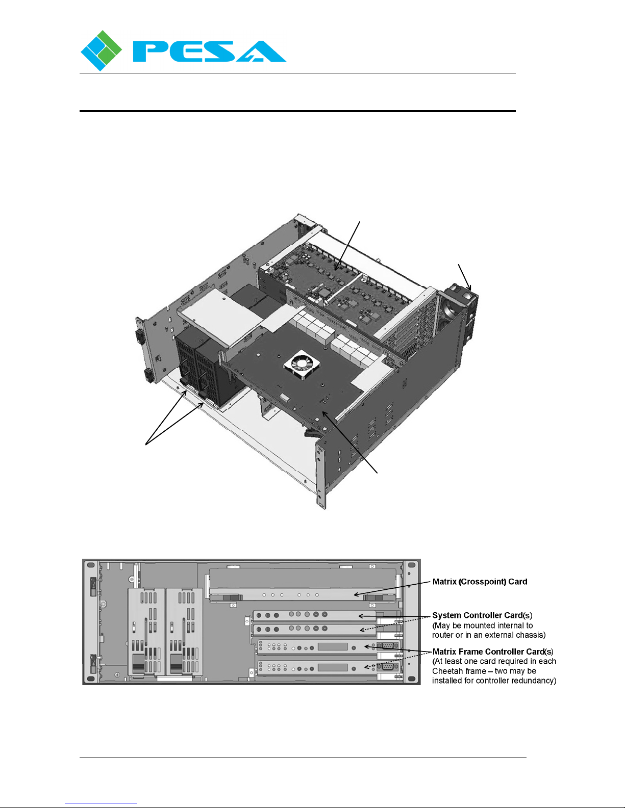
Chapter 3 C
HASSIS VIEWS AND SPECIFICATIONS
This chapter pictorially displays internal component layout of the switcher, identifies input
and output connections, and lists system specifications.
3.1 C
HEETAH
64NEX F
RAME VIEWS
Input/Output Cards
Fans
Power Supplies
Matrix Card
F
IGURE
3-1 Cheetah 64NEX Front Views
Proprietary Information of PESA
3-1
Page 9
Cheetah 64NEX Digital Video Router
Publication 81-9059-0685-0, Rev. A
March 2011
F
IGURE
Proprietary Information of PESA
3-2 Cheetah 64NEX Rear View
3-2
Page 10

3.2 S
Digital Specifications
Inputs / Outputs for Coax
Connector Type BNC - 75Ohm
Return Loss >15dB from 5Mhz to 1.5Ghz
>10dB, 1.5Ghz to 3GHz
Input cable equalization SMPTE 259M - 300m
SMPTE 292M - 100m
SMPTE 424M - 80m
Based on Belden 1694a or equal
Output Signal Level 800mV, p-p, +/-10%
Output Signal Polarity Non-inverted
Inputs/Outputs for Fiber
Connector Type Dual Optical SFP (small form factor
pluggable)
Compliance with ITU-T G.957
Connector Style LC
Input Data Rates 143 Mbps to 1.5Gbps - ASI/SD/HD
143 Mbps to 3.0Gbps - SD/HD/3G
Optical Input wavelength Singlemode ( 1310 optimal)
Input Power -20dBm (min)
-1dBm (max)
Output Data Rates 143 Mbps to 3.0Gbps
Auto reclocking to SMPTE 259M, 292M
424M. Bypass mode - 143Mb to 3Gbps
Output Power -9dBm (min)
-3dBm (max)
Optical Loss Budget Approx. 9dB
assumes two optical connections over
a 10Km singlemode fiber
Jitter < 0.2UI, p-p, SMPTE 259M, 292M
<0.3UI, p-p, SMPTE 424M
compliant with RP-184
Fiber Transmission Specifications IEC 61754-20-1
Typical Operating Distances 9/125u ( 10Km / 6.25 miles)
50/125u (400m / 1200 feet)
62.5/125u (200m / 600feet)
PECIFICATIONS
Cheetah 64NEX Digital Video Router
Publication 81-9059-0685-0, Rev. A
March 2011
Proprietary Information of PESA
3-3
Page 11

Cheetah 64NEX Digital Video Router
Publication 81-9059-0685-0, Rev. A
March 2011
NOTE
Operating distances are approximate only. Cable loss and other
interconnects can affect the total light loss between a TX and RX path. These
are only estimates and may not reflect the actual lengths achievable.
Digital Signal Performance
Inputs / Outputs for Coax
Re-clocking Auto-detect compliant with
SMPTE 259M, 292M, 424M
Rise/Fall Time < 600 ps, +/- 10% | SMPTE 259M
< 270 ps, | SMPTE 292M
< 135ps, | SMPTE 424M
Overshoot < 10% of amplitude ( max.)
Alignment Jitter < 0.2UI , 100kHz to 150MHz
< 0.3UI, 150MHz to 300MHz
Timing Jitter <1.0UI from 10Hz to 100kHz | SMPTE
259/292
< 2.0UI from 10Hz to 100kHz | SMPTE
424M
Operational Mode Selections AUTO - detects correct signal type
MANUAL - force to a specific format
BYPASS - allow signals to pass w/o
reclocking
Data Rates Supported 143Mbps to 3.0Gbps
Sync Reference Specifications
Sync Input Connector BNC X2
Sync Input Impedance 75 Ohm
Sync Input Return Loss > 40dB, 100kHz to 5MHz
Sync Input Level 0.37V p-p to 4.0V p-p
Sync Input Type NTSC, PAL, Black Burst, or HD Tri-Level
Environmental
Cooling Forced air front to back
Operating Temperature 0-40 degrees (C)
Operating Humidity 10-90% non-condensing
Proprietary Information of PESA
3-4
Page 12

Cheetah 64NEX Digital Video Router
Publication 81-9059-0685-0, Rev. A
March 2011
AC power connections
64NEX IEC - 60320 connector
95VAC to 240VAC, 47-63Hz
600 W Max
Safety and Conformance
FCC, CE, UL, RoHS
Warranty 3 years parts and labor
Control and Interfaces
Panel communications RS-485 / 3 pin detachable
Control communications RS-232 / 422 / Ethernet
Connector type 9 pin D-SUB, RJ-45
Control system PESA PERC2000
Third Party Interfaces use PESA CPU Link
Network Software Cattrax Net Control Software
Number of Panels per frame 256 (PERC2000 System Controller)
Cooling
Internal cooling fans with auto sensing speed adjustments
64NEX 2 fans
Mechanical
Dimensions 19.00W X 7.00H X 21.00D
482.6mm X 177.8mm X 533.4mm
Specifications subject to change without notice
Proprietary Information of PESA
3-5
Page 13
Cheetah 64NEX Digital Video Router
Publication 81-9059-0685-0, Rev. A
March 2011
Chapter 4 I
4.1 U
4.2 C
NPACKING AND INSPECTION
This equipment contains electrostatic sensitive devices (ESD). Use a grounded
wrist strap, grounding mat, and/or comply with local established ESD
procedures when handling the internal circuit cards to prevent destruction
from electrostatic discharge.
Immediately upon receipt, inspect all shipping containers. Carefully unpack the equipment and
compare the parts received against the packing list. If any parts appear to be missing or damaged,
please contact PESA immediately.
HOOSING A LOCATION
This equipment is designed for installation in a standard 19" equipment rack located in an
environment conforming to the specifications for each chassis. Locate each unit as closely as
possible to its associated equipment to minimize cable runs.
NSTALLATION
For local electrical compliance, this equipment should be located near the
socket-outlet, power strip (if plugs are used), or the supply
disconnect/breaker so that the AC line cord plugs or the supply disconnect
are easily accessible.
Consider the connection from this equipment to the supply circuit, and the effect that possible
overloading can have on overcurrent protection circuits and supply wiring. Refer to nameplate
ratings when addressing this concern.
4.3 M
OUNTING A CHEETAH ROUTER CHASSIS IN AN EQUIPMENT RACK
The weight of a fully loaded 64NEX chassis is 60 lbs nominal. Installation or
removal of this equipment requires at least two persons in order to avoid
possible personal injury or equipment damage. Install this equipment in such
a manner as to avoid any tipping hazard from uneven loading of the rack.
Make sure that all power is disconnected (Lockout/Tagout) before installing
the specific frame into the rack.
Fans that are mounted on this equipment provide forced-air cooling. Do not
block airflow around these fans. Replace all service panels and blank filler
plates. Keep the chassis door closed during normal operation.
Proprietary Information of PESA
4-1
Page 14
Cheetah 64NEX Digital Video Router
Publication 81-9059-0685-0, Rev. A
March 2011
This equipment is designed for installation in a standard 19" equipment rack. Provide sufficient
space behind the equipment racks to allow for control, signal, power cables, and free airflow after
all cables are installed. Use all chassis mounting holes and tighten mounting hardware securely
by using the rack equipment manufacturer’s suggested torque settings.
Install the equipment into the rack as follows:
1. Carefully, remove the equipment from the packing container and place the unit near the
rack where it will be installed.
2. Insert the chassis into the equipment rack and support the bottom of the chassis while the
mounting hardware is being installed.
3. Install the bottom two chassis mounting screws.
4. Install the top two chassis mounting screws.
5. Install any remaining chassis mounting screws.
6. Tighten all of the chassis mounting screws until they are secure. Release/remove the
support from the bottom of the chassis.
4.4 C
Use the following guidelines when connecting equipment cables:
ONNECTING EQUIPMENT CABLES
1. Install the equipment in the rack before connecting cables.
2. Relieve strain on all cables to prevent connector separation.
3. To the extent possible, separate control, signal, and power cables to minimize crosstalk and
interference.
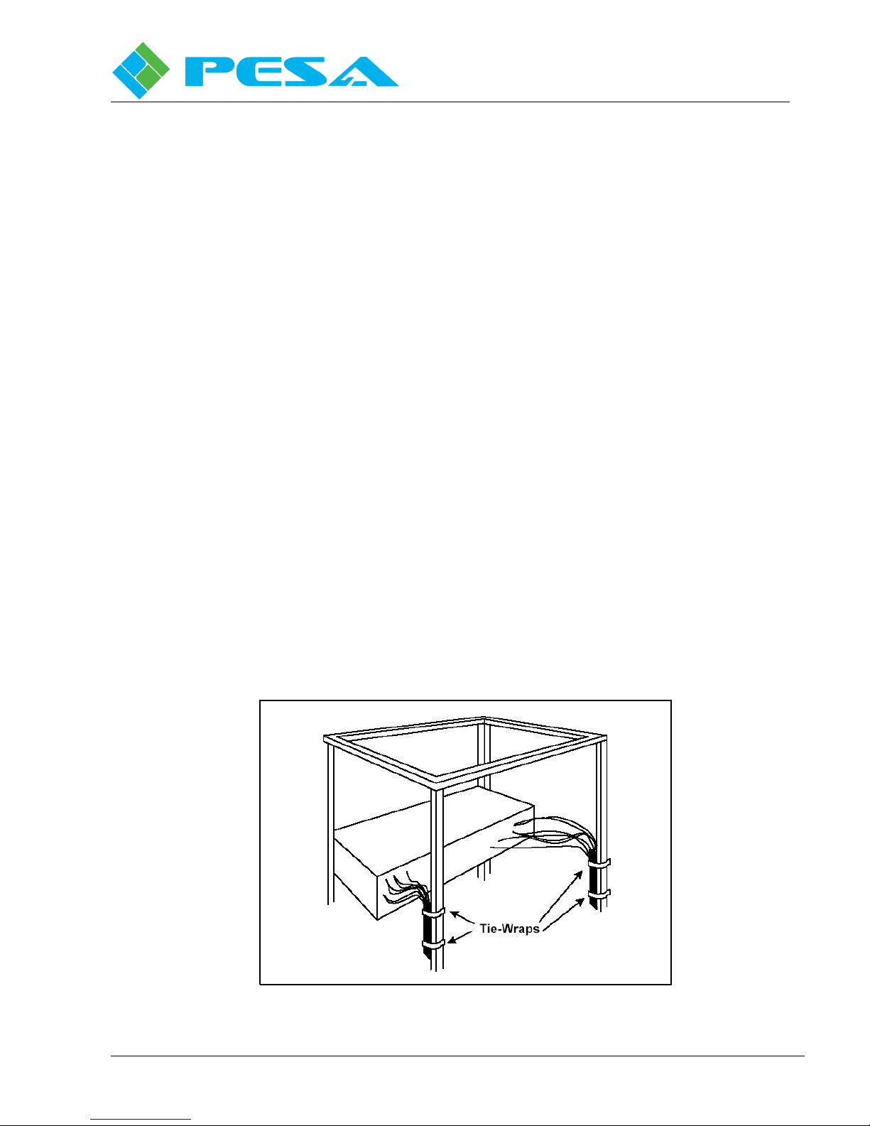
4. Use as many cable ties as necessary to secure cables to the rack (see Figure 4-1). This will
minimize the amount of force transmitted to the equipment and help route cables away from
hazardous areas.
Proprietary Information of PESA
F
IGURE
4-1 Cables Attached to Supports
4-2
Page 15

4.5 C
Once the Cheetah Video Matrix Switcher is installed in the equipment rack, the associated system
connections can be completed. Use the following guide to insure that interconnections are properly
connected and that the control, power, sync, and video cables are correctly installed (for further
detailed information, refer to the corresponding sub-section in this Chapter).
Cheetah 64NEX Digital Video Router
Publication 81-9059-0685-0, Rev. A
March 2011
5. Route cables away from physical traffic areas to avoid creating a safety hazard (trip or
shock).
6. Bundle together any cables connected to a single input/output card and separate them from
the other bundles with enough slack to create a service loop. This will permit individual card
replacement without disruption to the other input/output cards.
ONNECTION GUIDE CHECKLIST
1. Connect external sync sources to reference input BNC connectors using Belden 8281
coaxial cable or equivalent. Reference input BNC connectors are terminated into 75Ω
internal to the switcher.
2. Connect the PERC2000 System Controller to an Ethernet interface.
3. Connect a host PC to the system controller through the Ethernet interface.
4. If additional Cheetah Switchers are to be utilized as part of the switching matrix, connect
the PRC Loop jack on the primary Cheetah Switcher to PRC Loop jack on the other
Cheetah Switcher using 5-pin ribbon cables.
5. If an external system controller is used to control the Cheetah 64NEX, connect the external
controller to the COM 3 PRC port on the router rear panel using 9-pin RS-422 cable.
6. Connect the RCP control panels to the RCP Panel Ports (#1 and/or #2) using twisted pair
cables while observing polarity (refer to Chapter 7). Connections to control panel may be
daisy-chained.
7. Configure the Ethernet settings as described in Appendix A, paragraph 8.1 of this manual.
8. If SNMP management of additional Cheetah Switchers is to be utilized, connect the
switchers using the Frame Controller Ethernet connectors.
9. Configure the Ethernet and SNMP settings as described in the Appendices.
a. If desired, connect an external alarm to the System Control Alarm (for further
connection compliance information, refer to Chapter 7 for connector pin-outs).
b. If desired, connect an external alarm to the Frame Control Alarm (for further
connection compliance information, refer to Chapter 7 for connector pin-outs).
c. Connect video sources to router video input BNC connections.
d. Connect video output signals through the rear panel BNC connections to video
destinations.
Proprietary Information of PESA
4-3
Page 16

Cheetah 64NEX Digital Video Router
MOV
Bridge
Cheetah
+ VDC
MOV
Bridge
Cheetah
+ VDC
System
Publication 81-9059-0685-0, Rev. A
March 2011
4.6 C
All Cheetah frames have two AC receptacle power inputs. As depicted in Figure 4-2, each AC
power input is filtered, full-wave bridge rectified, and then fed to the power supply to be diode
OR’d with the other rectified power inputs to the system supply.
ACH 1
ACN 1
ACG 1
ACH 1
ACN 1
ACG 1
HASSIS SUPPLY POWER CONNECTIONS
Filter
Filter
Rectifier
Rectifier
(+)
Power
Supply
Out
(-)
DC Power
IN
(+)
Power
Supply
Out
(-)
F
4.6.1 Chassis Supply Power
Make sure that all source power is within the operating range of the
equipment before completing the specific power connections. Read the
Maximum Voltage requirements starting in this section (Chapter 6).
To prevent damage to the equipment:
•
Read all instructions for proper input voltage ranges.
•
4.6.1.1 Chassis Power Cord
AC power cords may differ depending on your power requirements. The chassis is supplied
with two USA standard power cords for 120VAC-power service (or the standards for the
country that the system is shipped to).
Use the recommended specified power branch circuit ampacity.
•
Follow static prevention precautions prior to handling equipment.
IGURE
4-2 Power Supplies Configuration
Proprietary Information of PESA
4-4
Page 17
4.6.1.2 Chassis AC External Power Requirements
The Cheetah router chassis is supplied with redundant, prefabricated, UL/CSA approved power
cords that include NEMA 5-15P male and IEC-60320-C13 female line connectors. These
cords are for connection to a 120VAC-supply service (refer to Table 4-1).
T
ABLE
4-1 AC Power Connectors
Cheetah 64NEX Digital Video Router
Publication 81-9059-0685-0, Rev. A
March 2011
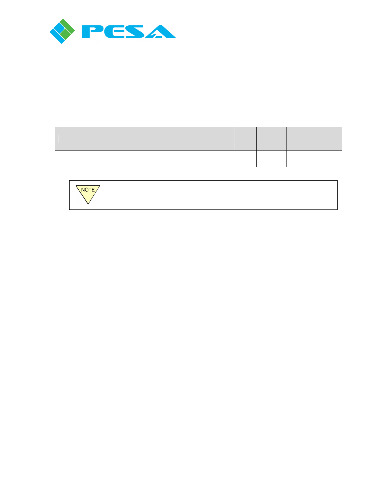
AC Power Cable
Minimum Amps
IEC-type line cord (120VAC connectors)
This AC power filter assembly has been designed for 95-240VAC, which
includes connectors and cords specified to handle maximum power
requirements.
4.6.2 International Power Requirements
All Cheetah frames have two AC Main power feeds, which are isolated from each another. All
international power requirements are pre-configured at the factory and commercially available,
prefabricated power cords designed for the power source that the equipment will be operating are
supplied with each unit.
As in the United States, international operation with one power supply is the normal, non-option
condition. An optional second (redundant/backup) power supply is available. Typical full-frame
power consumption is approximately 6.0 Amps or approximately 650 Watts at 240 VAC nominal
regardless of the number of power supplies in use.
Required
10A Service
IEC Pigtail Service Drops
Yes No
1-Standard
1-Redundant
4.7 C
HEETAH
64NEX C
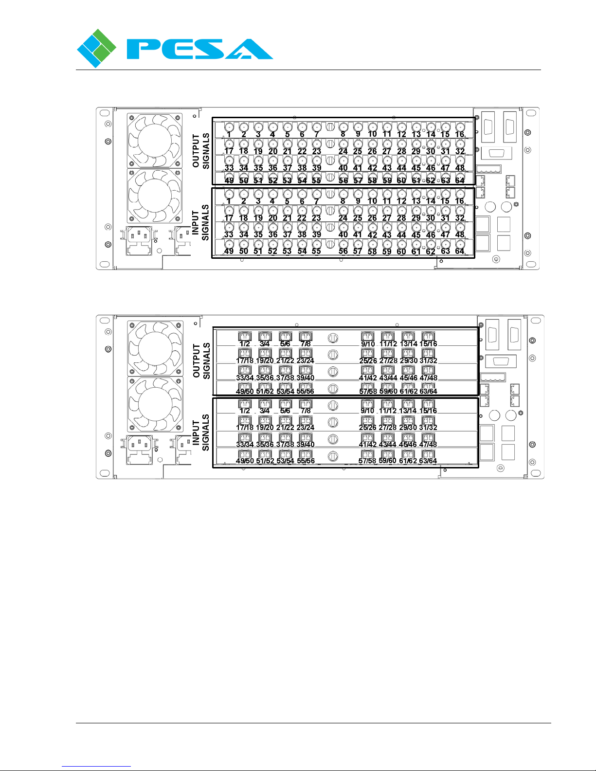
Each input or output card supports 16 video signals and installs to the rear of the 64NEX frame. I/O
card variants are available with BNC connectors or SFP fiber optic connectors. Figure 4-3
illustrates signal connections to each type of card. Use these illustrations as a guide when
completing video connections to the router.
Proprietary Information of PESA
HASSIS INPUT/OUTPUT SIGNAL CONNECTORS
4-5
Page 18
Cheetah 64NEX Digital Video Router
Publication 81-9059-0685-0, Rev. A
March 2011
A) BNC I/O Connections
F
IGURE
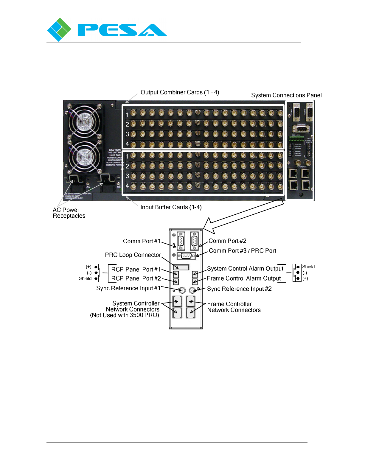
4.8 C
HASSIS SYSTEM CONNECTION LOCATIONS
System interface connections are made through rear panel connectors as shown by Figure 4-4. Each
interface connection is discussed in the following paragraphs. Complete system connections to the router
in accordance with the following procedures.
Proprietary Information of PESA
B) Fiber Optic I/O Connections
4-3 Cheetah 64NEX Input/Output Signal Connectors
4-6
Page 19
Cheetah 64NEX Digital Video Router
Publication 81-9059-0685-0, Rev. A
March 2011
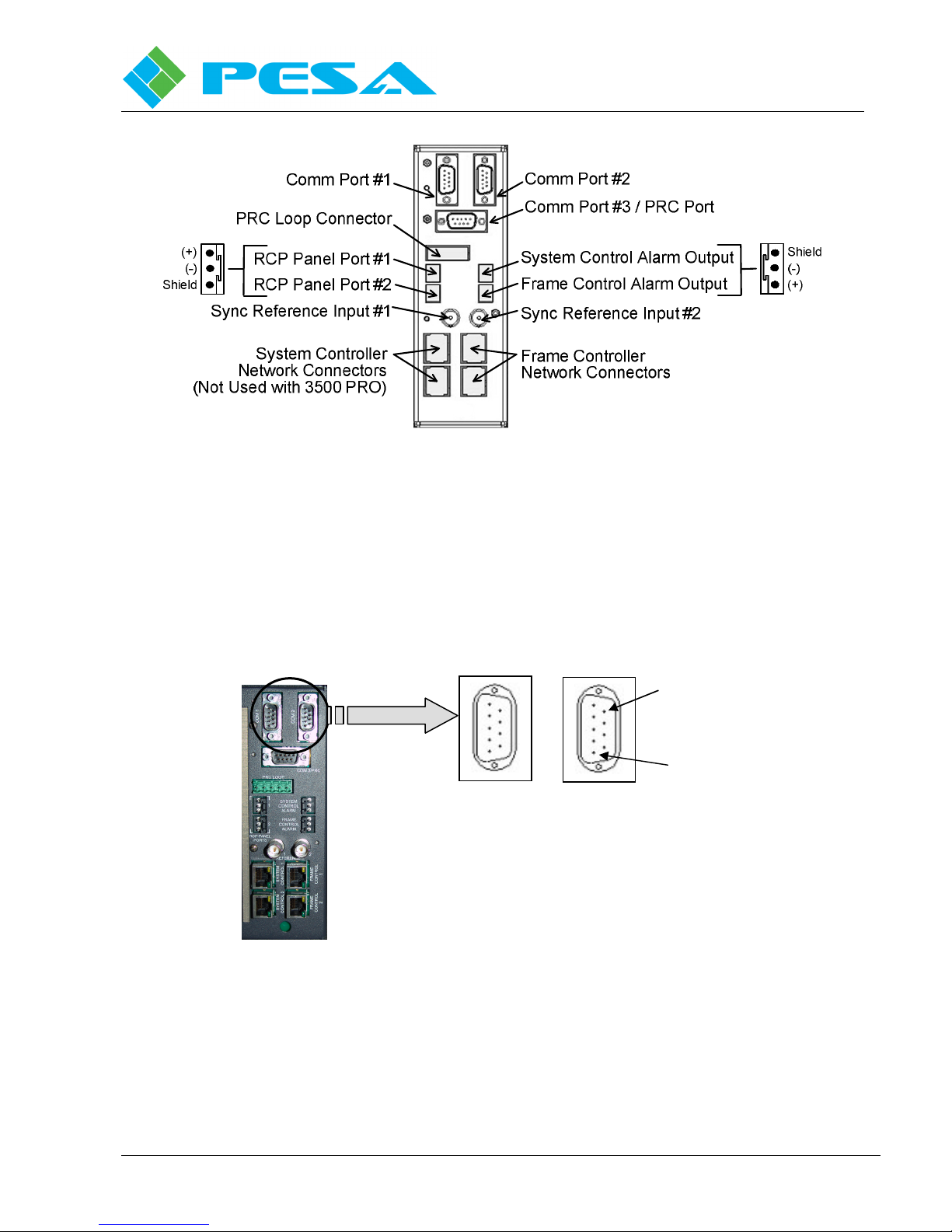
F
IGURE
4-4 Chassis System Interface Connector Locations and Descriptions (Rear View)
4.9 R
EAR PANEL CONNECTORS
4.9.1 RS-232 Control Connectors COM 1 and COM 2
COM 1 and COM 2 (see Figure 4-5) are DB-9 Male connectors that provide RS-232 serial
communication interfaces. Pin-outs are shown in Table 4-2.
F
IGURE
4-5
COM 1
RS-232 Control Connectors
Pin 9
Pin 1
COM 2
Proprietary Information of PESA
4-7
Page 20
Cheetah 64NEX Digital Video Router
Publication 81-9059-0685-0, Rev. A
March 2011
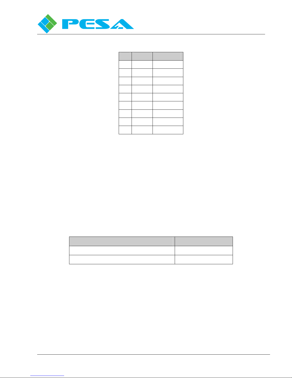
T
ABLE
4-2 COM1 and COM 2 Pin Assignments
Pin Signal In/Out
1 CD Input
2 RX Input
3 TX Output
4 DTR Output
5 Ground --6 DSR Input
7 RTS Output
8 CTS Input
9 RI No Connect
• COM 1 is the primary RS-232 CPU Link and may be connected with a null modem cable
(Part No. 81-9028-0393-0) to an external control device, using the P1E protocol at either
9600 or 38,400 baud. Set the baud rate with a switch on the controller board. Make sure
the communication rate for COM 1 in the system controller software matches the baud rate
you are using (in the software, select System > Communications).
• COM 2 is a secondary RS-232 CPU Link, which may also be connected to a PC or an
external control device. COM 2 may be used with either of the protocols shown in Table
4-3 and may operate at either 9600 or 38,400 baud. Set the baud rate with a switch on the
controller board. Make sure the communication rate for COM 2 in the system controller
software matches the baud rate you are using (in the software, select System >
Communications).
T
ABLE
4-3 PESA CPU Link Protocols
PROTOCOL DOCUMENT #
CPU Link Protocol No. 1 Extensions (P1E) 81-9062-0408-0
Unsolicited Status Protocol (USP) 81-9062-0409-0
Proprietary Information of PESA
4-8
Page 21

Cheetah 64NEX Digital Video Router
Publication 81-9059-0685-0, Rev. A
March 2011
4.9.2 RS-422 Control Connectors COM3/PRC
This DB-9 Male connector (see Figure 4-6) provides an RS-422 serial communication interface.
Pin 1
F
IGURE
4-6 RS-422 COM 3/PRC Control Connector
Pin 9
COM 3/PRC is the communications interface to a PRC type routing switcher system and is
connected to a routing switcher with a serial control cable (refer to Table 4-4 for pin
assignments).
T
ABLE
4-4 COM 3/PRC Pin Assignments
Pin
Signal In/Out
1 CTS+ Input (not used)
2 MATRIX+ Bi-directional
3 CTLR- Output
4 RTS- Output (not used)
5 Ground --6 CTS- Input (not used)
7 MATRIX- Bi-directional
8 CTLR+ Output
9 RTS+ Output (not used)
Proprietary Information of PESA
4-9
Page 22

(+)
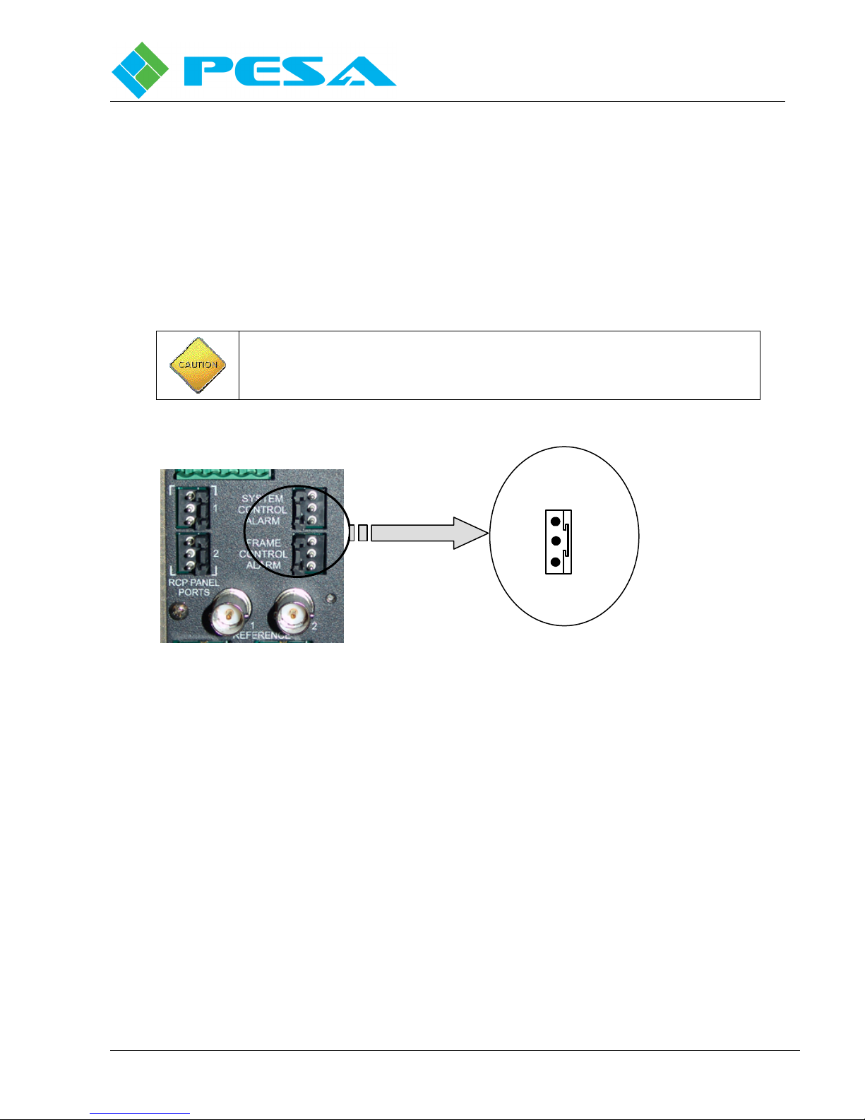
4.9.3 System Control Alarm Connector
This three-pin connector, illustrated in Figure 4-7, provides an interface for an external,
customer-supplied, system control alarm (alarm contact locations are also shown).
Cheetah 64NEX Digital Video Router
Publication 81-9059-0685-0, Rev. A
S
YSTEM CONTROL
A
LARM CONNECTOR
(-)
S
March 2011
F
IGURE
4-7 System Control Alarm Connector
The system controller initiates a system alarm when the controller is in reset and when the
standby controller is gathering configuration information from the primary controller. During an
alarm condition, an optically isolated, electronically closed circuit (see Figure 4-8 on next page)
exists between contacts 3 and 1 for Controller A (top) and contacts 2 and 1 for Controller B
(bottom). This circuit acts as a switch to trigger an optional external alarm in the event of a
controller fault or failure. The controller alarm circuit supplies an electronic contact closure, but
does not provide a voltage to the external alarm.
The Customer-supplied alarm circuit voltage to this connector must not
exceed 12VDC and the associated amperage must not exceed 10mA.
The alarm is activated if any of the following system controller software conditions exist:
• Encounters an interrupt that it does not expect or can not process.
• Is unable to synchronize with the second system controller (dual controllers).
• Does not get the configuration from the active system controller (dual controllers)
The customer supplied external alarm circuit is connected with a cable constructed as shown in
Figure 4-8.
Proprietary Information of PESA
4-10
Page 23

Cheetah 64NEX Digital Video Router
RL B
RL A
Publication 81-9059-0685-0, Rev. A
March 2011
The Customer-supplied alarm circuit voltage to this connector must not
exceed 12VDC and the associated amperage must not exceed 10mA.
Part Number
81-9029-0811-0
Customer
Supplied
Connector
Alarm B
Alarm A
Cheetah
Internal
F
IGURE
4-8 Alarm Cable Setting and Associated Schematic
4.9.4 PRC Loop Connector
This five-contact connector, located on the rear of the unit, is a loop-through connector used to
provide an RS-422 serial communication interface using the PESA PRC Protocol (Document No.
81-9062-0316-0). It is wired in parallel with the DB-9-Male PRC Loop connector. Contact
locations are illustrated in Figure 4-9.
+
1
Controller B (Bottom) Alarm (+)
_
2
3
Controller A (Top) Alarm (+)
S
Alarm (-)
2
1
3
2
1
3
Alarm B V+
Customer
Supplied
Alarm A V+
Proprietary Information of PESA
5 4 3 2 1
F
IGURE
4-9 PRC Loop Connector
4-11
Page 24

Cheetah 64NEX Digital Video Router
S
S
Publication 81-9059-0685-0, Rev. A
March 2011
PRC Loop may be connected to PESA PRC-type equipment with a cable assembly (Part No. 819028-0395-0) constructed as shown in Figure 4-10.
System Controller Tx+ (High)
System Controller Tx- (Low)
Chassis Ground
System Controller Rx+ (High)
System Controller Rx- (Low)
F
4.9.5 RCP Panel Port Connectors
Two RCP connectors, located on the rear of the unit and illustrated in Figure 4-11, provide RS485 serial communication interfaces using the PESA RCP Protocol (Document No. 81-90620300-0).
IGURE
1
2
3
4
5
4-10 RS-422 System Expansion Cable
PESA P/N: 81-9028-0395-0
PRC Cable Assembly
RCP #1
(-)
(+)
System Controller Tx+ (High)
1
System Controller Tx- (Low)
2
Chassis Ground
3
System Controller Rx+ (High)
4
System Controller Rx- (Low)
5
These RCPs are connected to PESA Remote Control Panels with daisy-chained cables
constructed with RCP connectors (Part No. 81-9029-0780-0) and shielded, twisted-pair cable
(Part No. 81-9028-0043-2, Belden 8451, or equivalent) as illustrated in Figure 4-12. The
connector body has an integral strain relief, which requires the use of a nylon cable tie, which is
included with the connector. If cable tie is not available, use PESA Part No. 81-9021-0028-8.
Proprietary Information of PESA
F
IGURE
(-)
(+)
RCP #2
4-11 RCP Panel Port Connectors
4-12
Page 25

Cheetah 64NEX Digital Video Router
Publication 81-9059-0685-0, Rev. A
March 2011
81-9029-0811-0 to
Panel Port Connector
81-9029-0780-0 to
Remote Control Panel
High (+)
Low (-)
Shield(S)
4.9.6 Network Connectors
The RJ-45 Ethernet connectors, illustrated in the Figure 4-13, connect the Matrix Frame
Controllers and System Controllers to a 10 or 100Mb/s TCP/IP network. Ethernet configuration
options are detailed in the Appendix.
1
3
2
High (+)
1
Low (-)
2
Shield(S)
3
1
2
3
Cable is not pin for pin! Pins 2 and 3 are swapped.
F
IGURE
4-12 RS-485 Cable Construction
1
2
3
F
IGURE
4-13 Network Connectors
LED indicators are provided as follows (see Figure 4-14 and refer to Table 4-5):
Proprietary Information of PESA
4-13
Page 26

Cheetah 64NEX Digital Video Router
Matrix Frame
System Controller
Publication 81-9059-0685-0, Rev. A
March 2011
F
T
ABLE
IGURE
4-14 Ethernet Connector
4-5 Ethernet LED Indicators
LNK ON = Ethernet LINK established
100M ON = The Ethernet connection speed is 100Mb/s
OFF = The Ethernet connection speed is 10Mb/s
To connect the cards to the network, do the following:
1. Set the IP address, Subnet mask, Gateway address, and Trap address on Matrix Frame
Controller and System Controller to addresses approved by the Network Administrator.
2. Using a straight through RJ-45 Ethernet cable, connect the Ethernet jacks to a
10/100BASE-T hub or switch on the TCP/IP network.
The Slot A Network Frame Control is for the Matrix Frame Controller in Slot A. The Slot B
Network Frame Control is for the Matrix Frame Controller located in slot B. The Slot A System
Control is for the System Controller located in Slot A. The Slot B System Control is for the
System controller located in slot B (see Figure 4-15 for typical slot locations).
Cards
Slot A
Slot B
Slot A
Slot B
Controller Cards
F
IGURE
Proprietary Information of PESA
4-15 Typical Matrix Frame Controller Cards locations, Slot A and Slot B
4-14
Page 27
(+)
4.9.7 Frame and System Alarm Connectors
The three-pin connectors, illustrated in Figure 4-16, provide an interface for an external,
customer-supplied frame and system control alarm. The Matrix Frame Controller determines
when a frame alarm condition is declared while the System controller determines when a system
alarm condition is declared. Alarm contact location is illustrated in Figure 4-17 on the next page.
This circuit acts as a switch to trigger an optional external alarm in the event of a
controller/system fault or failure. The alarm circuit supplies an electronic contact closure, but
does not provide a voltage to the external alarm. The customer-supplied external alarm circuit is
connected with a cable constructed as shown in Figure 4-17 (next page).
The Customer-supplied power input to this connector must not exceed
12VDC and the associated amperage must not exceed 10mA.
Cheetah 64NEX Digital Video Router
Publication 81-9059-0685-0, Rev. A
March 2011
F
RAME AND SYSTEM
C
ONTROL ALARM
C
ONNECTOR
(-)
S
F
IGURE
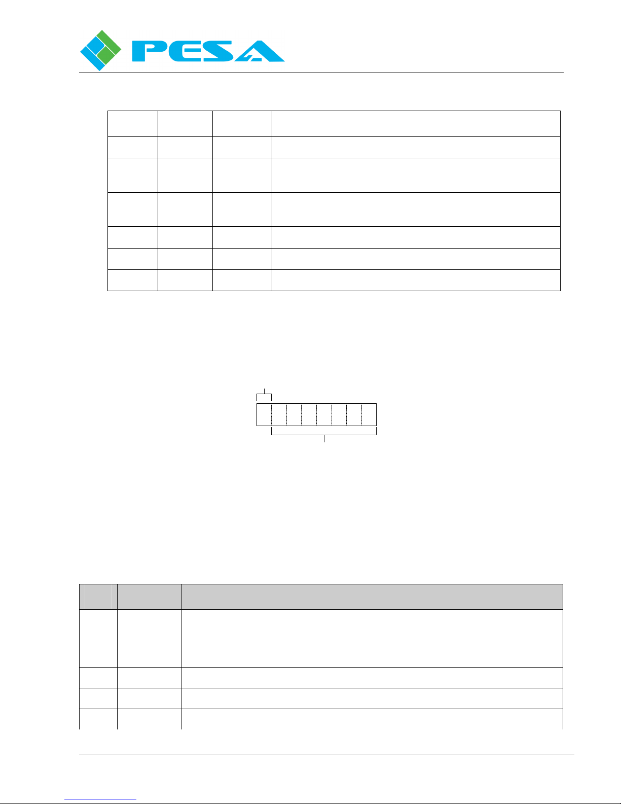
The Frame Control alarm is activated if any of the following matrix frame controller conditions
exist:
• Detects a card (input, output, matrix, output monitor, power supply, or matrix frame
controller) with a temperature out of range (above 114 ºF)
• Detects a fan’s voltage out of range
• Detects a power supply’s voltage or current out of range. The voltage or current must be
out of range for three consecutive times before the Matrix Frame Controller will indicate
an alarm.
The System Control alarm is activated if any of the following system conditions exist:
• Detects a system interrupt (i.e., a CPU failure/error, an address error, or an illegal
instruction)
• Synchronization problem with dual system cards
• The system configuration is not properly relayed to the dual system cards
• Whenever the system software is being upgraded
Proprietary Information of PESA
4-16 Frame and System Control Alarm Connector
4-15
Page 28

Cheetah 64NEX Digital Video Router
RL B
RL A
Publication 81-9059-0685-0, Rev. A
March 2011
The Customer-supplied alarm circuit voltage to this connector must not
exceed 12VDC and the associated amperage must not exceed 10mA.
Part Number
81-9029-0811-0
Customer
Supplied
Connector
+
1
Controller B (Bottom) Alarm (+)
_
2
3
Alarm B
Controller A (Top) Alarm (+)
S
Alarm (-)
2
Alarm A
1
Cheetah
Internal
3
F
IGURE
4-17 Alarm Cable Connection and Circuit Schematic
4.9.8 House Synchronization Input Connectors
These BNC coaxial connectors, illustrated in Figure 4-18, provide the interface for two, house
synchronization signals (i.e., NTSC, PAL, 1080i, 1080P, and 720P only). The house sync inputs
are individually terminated internally. The synchronization signal cannot be daisy-chained from
one routing switcher to another.
2
1
3
Alarm B V+
Customer
Supplied
Alarm A V+
(Internal 75 Ohm Termination)
F
IGURE
Proprietary Information of PESA
Ref 1
4-18 House Sync Input (Reference) Connectors
Ref 2
4-16
Page 29

4.10 S
Cheetah 64NEX Digital Video Router
Publication 81-9059-0685-0, Rev. A
March 2011
Using the Cheetah GUI, the user can assign a specific reference signal for the system or
individual chassis that is used as a synchronization signal for specific output synchronized
switching. Once the output has been switched, the output signal remains synchronized to the
initial reference assignment until it is switched again with a new reference assignment. An
example of a sync assignment would be as follows:
Reference 1 is connected to an NTSC sync signal source and Reference 2 is connected to a
PAL sync signal source. Using the GUI, the user assigns Reference 1 to outputs 6 through 10
and Reference 2 to outputs 11 through 16 for a specific chassis.
Reference 1 or 2 should be connected to the house sync source or tri-level source with coaxial
cable and standard BNC connectors.
ETTING CHASSIS LEVEL CODES (STROBES
)
Chassis Level Codes (Strobes) assign operational parameters to the switcher frame. There are
seven rotary switches, located just to the right of the power supply modules and accessible from the
front of the router, used to set the chassis level code and other frame operational characteristics.
Chassis switch settings are preset at the factory and should never need any maintenance or
adjustment. This information is provided as a reference so that in the event any switch setting
should inadvertently be changed, it can be restored to its correct setting.
Proper setting positions for these switches are shown in Figure 4-19.
Prior to adjusting any of the chassis strobe switches, it is strongly
recommended that you contact PESA’s Customer Service Department for
assistance.
Proprietary Information of PESA
4-17
Page 30

Cheetah 64NEX Digital Video Router
Publication 81-9059-0685-0, Rev. A
March 2011
Example settings shown are for the 64NEX chassis.
0
1F
2
Level
MSB
LSB
E
D
3
4
C
B
D
C
B
S1
5
A
6
9
7
8
0
1
F
2
E
3
S2
4
5
A
6
9
7
8
Output
S1 = 0
S2 = 1
S3 = 0
S4 = 0
S5 = 0
S6 = 0
S7 = Not Used or Installed
S8 = 7
Input
Frame
MSB
LSB
MSB
LSB
F
2
E
D
3
4
C
B
D
C
B
D
C
B
D
C
B
D
C
B
S3
5
A
6
9
7
8
0
1
F
2
E
3
4
S4
5
A
6
9
7
8
0
1
F
2
E
3
4
S5
5
A
6
9
7
8
0
1
F
2
E
3
4
S6
5
A
6
9
7
8
0
1F
2
E
3
4
S8
5
A
6
9
7
8
0
1
F
IGURE
4-19 C
HEETAH
64NEX C
Proprietary Information of PESA
HASSIS STROBE SWITCH LOCATION AND SETTINGS (FRONT VIEW
)
4-18
Page 31

The level code identifies the matrix level of the router.
4.10.1 Chassis Strobe Switch Functions
R
OTARY
S
WITCH
N
AME
D
Cheetah 64NEX Digital Video Router
Publication 81-9059-0685-0, Rev. A
March 2011
ESCRIPTION
S1
S2
Most Significant Bit
(MSB) Level Code
Least Significant Bit
(LSB) Level Code
This setting accepts 1 to 63 in binary (1 to 3F in
hexadecimal). This setting must match the Strobe setting
assigned through the System Controller.
This strobe is used to offset output origin when frames
S3 MSB Output Offsets
are added to the system. This setting accepts 1 to 255 in
binary (1 to FF in hexadecimal). Set this strobe to the
first offset number you want to use in this unit. This
S4 LSB Output Offsets
setting must match the Output Offset setting in the
System Controller.
S5
MSB Input Offsets
This strobe is used to offset input origin when frames are
added to the system. This setting accepts 1 to 255 in
binary (1 to FF in hexadecimal). Set this strobe to the
first input number you want to use for this unit. This
setting must match the Input Offset setting in the System
Controller.
S6
LSB Input Offsets
S7 Not Used or Installed with 64NEX Frame
S8 Frame Specifies the type of frame the boards are plugged into.
Proprietary Information of PESA
4-19
Page 32

Cheetah 64NEX Digital Video Router
Publication 81-9059-0685-0, Rev. A
March 2011
Chapter 5 F
This section addresses the system components, frame, and control verification sequences that should be
performed prior to energizing the system and placing the system in service. Attention to this section
will minimize system startup and in-service malfunctions.
5.1 S
5.2 S
YSTEM PRE-START VERIFICATION CHECKLIST
A system pre-start verification checklist includes a visual inspection to account for basic setup
functions that, if incorrect, could result in immediate system startup malfunctions. The following
basic checks should be performed prior to energizing any Cheetah chassis:
1. Verify the main power source is OFF (de-energized).
2. Verify all cards/modules are latched and secure.
3. Verify all blank covers are in place and secure (no open slots in the frame).
4. Verify the line cord(s) are connected to the chassis and are properly terminated to the source
power distribution system (i.e., connectors plugged in or pigtails terminated).
5. Inspect for unusual items such as loose wiring, frayed cabling, loose connections or
components, and missing cards/modules (basically, check for anything that seems out of
place or could present a problem).
6. Proceed to System Startup.
YSTEM STARTUP
Perform the Cheetah system startup sequence as follows:
RAME AND CONTROL VERIFICATION
1. Energize the main power source to the chassis.
Result: The system has a 30 to 45 second delay prior to energizing the components. When
the delay has expired, the system will energize and the cards will perform initial
self-diagnostics.
Verify the blank-cover panels are securely in place. These panels are an
integral part of the chassis cooling system. A loose, broken, and/or missing
blank-cover panel could result in destructive overheating of equipment
components.
Proprietary Information of PESA
5-1
Page 33

Cheetah 64NEX Digital Video Router
Publication 81-9059-0685-0, Rev. A
2. Verify the following LED conditions:
If any LED conditions are different, perform troubleshooting sequences to
correct the problem(s) prior to placing the system in service.
a. On the Power Supply module, the Power OK LED is illuminated (green)
b. On the Matrix module, the following LEDs are illuminated:
•
+28 (green)
•
+2.5 (green)
•
+1.2 (green)
c. On the Matrix Frame Controller (MFC), the following LEDs and LED display are
illuminated (single or dual modules):
•
Single module: the Control Status display indicates - ØSNGL OK (red)
March 2011
•
Dual modules: the Control Status display of the active module indicates –
Active OK while the other module indicates Standby
•
Active (green – illuminated on single and Active modules only)
•
+28 (green)
•
+5 (green)
•
+3 (green)
d. On each of the Input and Output modules, the Power LED is illuminated (green).
At the end of this sequence, there should be no LED indicators that are
blinking or any red LEDs illuminated on any of the I/O and Matrix
modules/cards. If so, perform troubleshooting to correct the status before
proceeding to the next step or section.
Proprietary Information of PESA
5-2
Page 34

Cheetah 64NEX Digital Video Router
Publication 81-9059-0685-0, Rev. A
March 2011
Chapter 6 O
I
NSTALLATIONS
PERATIONAL DESCRIPTIONS AND CARD/MODULE
This section documents the operational descriptions of the various components of the Cheetah
Series Switchers. Typically, this section is accessed for more concise component information and
how each component is used in the Cheetah Series systems.
Additionally, this section will describe the installation of the various components of the Cheetah
Series Switchers. Even though the unit is shipped with all of the components preinstalled, this
section is typically accessed for basic component information and for their replacement (removal
and installation) sequences.
6.1 C
HEETAH SERIES POWER SUPPLIES
6.1.1 Cheetah Series Power Supply Information
Cheetah Series Power Supplies contain electrical shock hazards and should
only be serviced by qualified service personnel with experience in servicing
off-line switching regulators.
There are no user serviceable parts contained in the Cheetah Series Power
Supplies. All service performed on the Power Supplies should be performed
by the PESA Service Department.
High Leakage Current at 240VAC. The Cheetah Series Power Supply
leakage current exceeds 7.0mA when used at 240 VAC because of leakage
through emission filter capacitors.
The Cheetah Power Supply is responsible for providing a regulated ±28VDC @22A to the
switching frame. The Cheetah Power Supply is designed to operate automatically with input AC
line voltage ranges from 95-240 VAC and with AC line frequencies of 50/60 Hz. All Cheetah
power supplies have built-in, over-current protection circuitry. When two supplies are used, each
supply is electrically connected to a common/dedicated buss within the chassis.
Additionally, each power supply contains dual internal fan controller systems that are isolated
from the main DC power output buss connections. Depending on the chassis, there are
dependent power supply installation configurations to satisfy the fan operations. In a two-supply
system, one supply module becomes the master and the other becomes the slave.
In the event of a Cheetah Power Supply failure, return the malfunctioning unit to the PESA
Service Department for replacement. The power supplies contain lethal voltages when operating
and should be serviced only by the PESA Service Department. Please call the PESA Service
Department for a RMA number before returning any units for replacement. The Service
Department’s phone number is listed on the front page of this manual.
Proprietary Information of PESA
6-1
Page 35

Cheetah 64NEX Digital Video Router
Publication 81-9059-0685-0, Rev. A
6.1.2 Cheetah Series Chassis Power Supplies Locations and Allocations
The power supplies are located on the front of the frame as shown in Figure 6-1.
Power Supplies
F
IGURE
6-1 Cheetah 64NEX Chassis Power Supply Locations (Front Views)
March 2011
6.1.3 LED Indicators and Test Points
Three LED indicators and one test point are located on the front of the power supply, as
illustrated in Figure 6-2. The LED indicators are described in Table 6-1.
F
LED C
PWR
OK
Green
OLOR
IGURE
S
ON
6-2 Power Supply LED Indicators and Test Points
T
ABLE
6-1 Power Supply LED Indicators
TATUS
D
Indicates that the +28V power is stable and within normal operating
parameters.
ESCRIPTION
Temp Red
Current Red
ON
ON
Proprietary Information of PESA
Indicates there is an over-temperature condition in the power supply.
This must be corrected immediately!
Indicates there is an over-current condition in the power supply. This
must be corrected immediately!
6-2
Page 36

6.1.4 +28V Test Points
The test point labeled +28V is used to determine by measurement whether +28VDC power is
present (bare metal of the chassis can be used for the ground/negative potential).
6.1.5 Installing the Power Supplies
Install each power supply as follows:
1. Align the metallic support plate of the first power supply vertically with the card guides in
the chassis.
2. Press upward on the power supply latch located on the front bottom of the assembly and
carefully insert the power supply into the chassis until the connectors on the power supply
make contact with the backplane connectors.
3. Firmly, push the power supply unit into the chassis until the power supply latch engages
the corresponding slot in the chassis.
The latch on the power supply acts as a retainer latch and a power ON/OFF
switch for the unit.
Cheetah 64NEX Digital Video Router
Publication 81-9059-0685-0, Rev. A
March 2011
3. Make sure the latch is fully engaged (down and secured/mated into the corresponding slot in
the chassis) to enable (energize) the power supply.
6.1.6 Removing the Power Supplies
To remove a power supply, follow these steps (you may remove power supplies while the
Cheetah system is operational [energized], which is called hot-swapping):
Make sure you will still have the minimum number of power supplies
installed before removing power supplies. The minimum number depends
on your configuration, which is either one or two power supplies. If you
only have one supply installed and you must remove it, de-energize the unit
first.
1. Open the Cheetah front cover.
When the latch on the power supply is moved to the full-upward position,
the power supply is switched off and is freed from the retaining slot in the
chassis.
Proprietary Information of PESA
6-3
Page 37

Cheetah 64NEX Digital Video Router
Publication 81-9059-0685-0, Rev. A
March 2011
2. Push and hold the latch on the lower front of the power supply in the full-upward position.
3. Once the latch is pushed upward and held, use the unit handle and carefully pull the power
supply out of the equipment chassis (the unit is held in place by connector plugs and
requires a slight forceful-pulling motion to separate it from the connectors). Repeat for
each power supply that you need to remove.
6.2 I
NSTALLING INPUT BUFFER AND OUTPUT COMBINER CARDS
Install the input/output cards as follows (see Figure 6-3):
F
IGURE
6-3 Input/Output Signal Connectors (rear view)
1. Align the first input/output buffer card with the card guides in the chassis.
2. Carefully insert the input/output buffer card into the chassis until the screw makes contact
with the backplane. This will align the card with its’ corresponding backplane contact block.
3. Secure the screw using a 5/16” hex socket or a flat head screwdriver. As the screw is
tightened, the card is automatically seated into the contact block on the backplane.
4. Repeat the above steps for each additional input/output buffer card.
5. Reverse the order for removal of the card.
6.3 V
IDEO MATRIX (CROSSPOINT) CARD
The digital matrix card accepts video sources (143Mbps to 3Gbps) from the input buffer cards and provides
output signals to the output combiner cards. All switching is done by a special purpose device, controlled
by commands from the matrix frame controller. Any input signal may be routed to any or multiple output
channels of the card.
There are six LEDs located on the front edge of each matrix card that provide a visual indication of the
operational status of the card; these are identified by Figure 6-4. Table 6-2 lists the possible states and
interpretation data for the LEDs.
Figure 6-5 is a block diagram of the digital matrix card. Paragraph 6.4 presents a narrative description of
the circuit functions shown on the block diagram.
Proprietary Information of PESA
6-4
Page 38

Cheetah 64NEX Digital Video Router
Publication 81-9059-0685-0, Rev. A
March 2011
+28V
Green
Red
Yellow
(Amber)
Red
+2.5V
+1.2V
CTRL
ERR
IN
USE
FAN
ERR
F
IGURE
6-4 V
IDEO CROSSPOINT MATRIX CARD
LED I
NDICATORS
T
ABLE
6-2 V
IDEO CROSSPOINT MATRIX CARD
LED D
ESCRIPTIONS
LED C
OLOR
+28V Green
+2.5V Green
+1.2V Green
Ctrl Err Red
S
ON
OFF
ON
OFF
ON
OFF
ON
TATUS
D
ESCRIPTION
Indicates that the +28Vpower is stable and within normal operating
parameters.
Indicates that +28V is not stable; power supplies are not working.
Indicates that the +2.5Vpower is stable and within normal operating
parameters.
Indicates that +2.5V is not stable; power supplies are not working.
Indicates that the +1.2Vpower is stable and within normal operating
parameters.
Indicates that +1.2V is not stable; power supplies are not working.
Indicates that a control error has occurred, or that a loss of receive
clock from frame controller has been detected. A control error
includes a bad CRC of the received data, incorrect number of words
in the message being received, or corrupted data in the message being
received. The LED will remain on until a message with a good CRC
has been received.
Blinking
OFF
In Use Yellow
Fan
ERR
Red
ON
ON
Proprietary Information of PESA
Indicates a missing receive clock error.
No alert conditions are present.
Indicates that a crosspoint on the matrix card is activated.
Indicates a failure of the cooling fan on-board the crosspoint device. .
6-5
Page 39

Cheetah 64NEX Digital Video Router
Publication 81-9059-0685-0, Rev. A
March 2011
6.4 F
UNCTIONAL DESCRIPTION - DIGITAL VIDEO MATRIX CARD
Refer to Figure 6-5 as we discuss the various circuit functions of this card. There are 64 identical input
channel paths provided. Video signals are derived from the output channels of the input buffer cards and
routed to the inputs of the matrix card. As a signal enters the card it is routed to an Input Buffer stage,
internal to the crosspoint device. This device contains the switching circuitry to deliver a signal on any of
its input channels to any of its output channels. Switching data for the crosspoint device is received from
the on-board microcontroller circuitry. The crosspoint also contains output buffer stages, internal to the
device, for isolation. Video from each device channel is available at the card edge connector where it is
routed to the output combiner cards.
The On-Board Microcontroller is the interface between the matrix card and the frame control system. The
microcontroller constantly monitors the status and health of the card and reports this data to the system
frame controller. Commands from the frame controller are interpreted by the microcontroller circuitry and
select the active inputs and outputs of the crosspoint device. Data indicating the status of the operating
voltage rails is sent to the microcontroller by circuitry contained in the Voltage Regulator stage. The
microcontroller also provides a visual indication of certain board functions by controlling the operating
state of the status LEDs. Operating voltages necessary to power the matrix card circuitry are derived from
on-board voltage regulator devices.
28 VDC From
Power Supply
Module
System Control
Interface
Input 1
Signal Inputs
From Input
Buffer CCAs
Input 64 Output 64
Voltage Regulation
And
Distribution
On-Board
Microcontroller
Crosspoint
Matrix Array
With Internal
Buffer Stages
Power For All
Circuit Elements
Visual Status
LEDs
Output 1
Signal Outputs
To Output
Combiner CCAs
F
IGURE
Proprietary Information of PESA
6-5 B
LOCK DIAGRAM – DIGITAL VIDEO MATRIX CARD
6-6
Page 40

6.5 M
The matrix frame controller, located on the right front of the unit, is illustrated in Figure 6-6. For
every frame type, at least one Matrix Frame Controller (MFC) is required. The function of the
frame controller is to determine frame size, level, input offsets, output offsets, plus other physical
characteristics of the frame hardware. Both PESA’s PRC protocol and NET PRC protocol are
available to the MFC. With the NET-PRC protocol, the MFC has the ability to communicate to a
system controller via Ethernet connection. More features include SNMP support and redundant
MFC cards with auto changeover.
ATRIX FRAME CONTROLLER
Cheetah 64NEX Digital Video Router
Publication 81-9059-0685-0, Rev. A
March 2011
(MFC)
COMMUNICATIONS
+28
RX RX LNK VT2
+5
+3
TX
TX
ACT
PRC
422
NET
VT1
The MFC has the ability to provide dual operations. By setting each MFC with its own Ethernet
address, updates and active switching can be done in parallel that allows immediate crossover
during a card failure or network interruption (refer to Chapter 8, Appendix A for details on
Ethernet configuration options).
6.5.1 MFC LED Indicators
The matrix frame controller LED indicators are described in Table 6-3.
T
ABLE
LED C
+28V
OLOR
Green
Red
S
RESETACTIVE
CONTROL STATUS
SCROLL
88888888
MATRIX FRAME CONTROLLER
F
IGURE
6-3 Matrix Frame Controller LED Indicators
TATUS
ON
ON
6-6 Matrix Frame Controller
D
ESCRIPTION
Indicates that the +28V power is stable and within normal
operating parameters.
Indicates that +28V power is not stable.
RX
TX
Green
+5V
Red
Green
+3V
Red
PRC
Tx/Rx
422
Tx/Rx
ACT
NET
Proprietary Information of PESA
Green
Green
Green
ON
ON
ON
ON
ON
ON
ON
This LED, when on (green), indicates that the +5V power is
stable and within normal operating parameters.
Indicates that +5V power is not stable.
Indicates that the +3V power is stable and within normal
operating parameters.
Indicates that +3V power is not stable.
Indicate that PRC traffic is being transmitted or received.
Indicate that RS-422 traffic is being transmitted or received.
Indicates that network activity is present.
6-7
Page 41
Cheetah 64NEX Digital Video Router
Publication 81-9059-0685-0, Rev. A
March 2011
T
ABLE
6-3 M
ATRIX FRAME CONTROLLER
LED I
NDICATORS (CONT
.)
LED C
LNK Green
VT1/V
T2
Active Green
Reset Red
Rx Green
Tx Yellow
OLOR
Green
S
ON
ON
ON
ON
ON
ON
TATUS
6.5.2 MFC 8-Character Display
An eight-character display (see Figure 6-7) is located on the front of the matrix frame controller.
D
Indicates that a network connection exists.
Indicates that a sync signal is present.
Indicates the active controller (when dual controllers are in
use).
Indicates that the controller is in Reset mode.
Indicates that Receive data is being received.
Indicates that Transmit data is being transmitted.
Page
number
ESCRIPTION
The display is divided into two fields. The first character on the far left is the first field
indicating the page number of the information being displayed. The second field is comprised of
the next seven characters, and displays the actual message.
Press the “Scroll” button to view successive pages. Each page will appear for 30 seconds, then
reset to page 0. Descriptions of the displayed messages are detailed in Table 6-4.
P
AGE
M
ESSAGE
ACTV OK
STDB **
0
SNGL OK
SNGL **
1 IN XXXX
2 OUTXXXX
88888888
Message
display
F
IGURE
T
ABLE
D
Describes which frame controller is active, standby, or single operation. It also
indicates whether there is an alarm condition present on the controller.
Shows the number of inputs being controlled by the frame controller.
Shows the number of outputs being controlled by the frame controller.
6-7 8-Character Display
6-4 8-Character Display Messages
ESCRIPTION
3 IOFXXXX
Proprietary Information of PESA
Shows the input offset of the matrix.
6-8
Page 42

Cheetah 64NEX Digital Video Router
Publication 81-9059-0685-0, Rev. A
March 2011
P
AGE
M
ESSAGE
4 OOFXXXX
5 STRB XX
TEMP OK
6
TEMPBAD
PWR OK
7
PWR BAD
FAN OK
8
FAN BAD
PRC NO
9
PRC OK
PRC BAD
NET NO
A
NET OK
NET BAD
SYN1 NO
B
SYN1 XX
TABLE 6-4 8-C
D
HARACTER DISPLAY MESSAGES (CONT
ESCRIPTION
.)
Shows the output offset of the matrix.
Shows the PRC strobe of the matrix.
Shows the alarm status of the over temp indicator.
Shows the alarm status of the power supply.
Shows the alarm status of the fan circuit.
Describes whether the system is communicating via the PRC bus. If so, it indicates
whether it has detected any errors on the PRC communication bus.
Describes whether the system is communicating via the Network Communication. If
so, it indicates whether there have been any errors detected.
This indicates whether a valid SYNC 1 is present. The type of sync is encoded in the
XX.
SYN2 NO
C
SYN2 XX
XXX.XXX This is the first half of the IP address of the frame controller’s network node.
D
XXX.XXX This is the second half of the IP address of the frame controller’s network node.
E
INE OK
F
INE BAD
OTE OK
G
OTE BAD
MTX OK
H
MTX BAD
PSB OK
J
PSB BAD
INE OK
K
INE BAD
OTE OK
L
OTE BAD
MTX OK
M
MTX BAD
This indicates whether a valid SYNC 2 is present. The type of sync is encoded in the
XX.
Indicates whether there are any errors detected on any input cards.
Indicates whether there are any errors detected on any output cards.
Indicates whether there are any errors detected on any matrix cards.
Indicates whether there are any errors detected on any power supply cards.
Indicates whether there are any errors detected on any input cards.
Indicates whether there are any errors detected on any output cards.
Indicates whether there are any errors detected on any matrix cards.
PSB OK
N
PSB BAD
Proprietary Information of PESA
Indicates whether there are any errors detected on any power supply cards.
6-9
Page 43

6.5.3 MFC Switch Locations and Settings (S1 and S2)
S1 and S2 are eight-position, slide-style dipswitches consisting of eight, single-pole single-throw
(SPST) switches numbered 1 through 8, located on the face of the matrix frame controller card,
as illustrated in Figure 6-8.
These dipswitches are set at the factory. Do not change the settings!
S1
ON
1 2 3 4 5 6 7 8
OFF
ON OFF
11 23 45 67 8
S1
0
Cheetah 64NEX Digital Video Router
Publication 81-9059-0685-0, Rev. A
March 2011
0
1
ON
S5
ON OFF
0
11 23 45 6 78
S5
1 2 3 4 5 6 7 8
1
OFF
0
F
IGURE
6-8 MFC Dipswitch Locations
Proprietary Information of PESA
6-10
Page 44
Cheetah 64NEX Digital Video Router
Publication 81-9059-0685-0, Rev. A
March 2011
Chapter 7 M
AINTENANCE AND REPAIR
This section will address the normal system maintenance sequences, basic troubleshooting
scenarios, minor system repairs, and PESA (PESA Switching Systems, Inc.) contact information.
Since it may become necessary to perform maintenance and repair on energized equipment, it is the
responsibility of all personnel involved in the maintenance and repair of the equipment to be
familiar with all of the applicable safety regulations for the areas they will be working in. Under
no circumstances should any person perform any procedure or sequence in this manual if the
procedural sequence will directly conflict with local Safe Practices. Local Safe Practices shall
remain as the sole determining factor for performing any procedure or sequence outlined in this
document.
7.1 M
AINTENANCE
7.1.1 Maintenance Overview
This equipment has been designed to give long, trouble-free service with very little maintenance.
Under normal service conditions, the only routine maintenance required is to monitor the air
filter for cleanliness.
This equipment contains static sensitive devices. A grounded wrist strap and
mat should be used when handling the internal circuit cards.
This equipment has been designed so that maintenance operations can be
performed while the equipment is operational (energized and performing
switching functions). Only the power supply assemblies and the AC supply
line circuits contain potentially lethal shock hazards.
7.1.2 Air Filter
The air filter(s) should be checked monthly to ensure that an adequate supply of clean air is
available to cool this equipment. If the air filter is dirty, either clean it with low-pressure air,
vacuuming, or a mild soap-and-water solution (then dry); or replace it with a new air filter
(PESA Part No. 81-9065-2360-0).
7.2 R
Proprietary Information of PESA
EPAIR
Before attempting to repair this equipment, consult your warranty documents and/or PESA’s
Customer Service Department. Unauthorized field repairs may void your warranty.
Only Qualified service personnel using appropriate equipment should service
the Cheetah Series power supply assemblies in this equipment.
Consult PESA Customer Service before attempting to repair any of the PC
cards in this equipment.
7-1
Page 45

7.2.1 Replacement Parts
Only parts of the highest quality have been incorporated in the design and manufacture of this
equipment. If the equipment’s inherent stability and reliability are to be maintained, replacement
parts must be of the same high quality. For selection of exact replacement parts or for acceptable
replacement part substitutions, contact PESA’s Customer Service Department before installing
any parts not purchased from PESA, Inc.
7.2.2 Return Material Authorization (RMA)
Before returning any equipment for service or replacement, contact PESA’s Customer Service
Department for an RMA number. Contact information for the Customer Service Department
appears in Paragraph 7.5.
7.3 PESA C
7.4 C
HEETAH SERIES SUPPORT DOCUMENTATION
81-9062-0316-0: PESA Router Control (PRC) Protocol
USTOMER SERVICE
Cheetah 64NEX Digital Video Router
Publication 81-9059-0685-0, Rev. A
March 2011
7.5 PESA (PESA S
•
S
ERVICE AND ORDERING ASSISTANCE
PESA (PESA Switching Systems, Inc.)
103 Quality Circle
Suite 210
Huntsville, AL. 35806 - USA
www.PESA.com
•
M
AIN OFFICE
Tel: (256) 726-9200
Fax: (256) 726-9271
•
S
ERVICE DEPARTMENT
Tel: (256) 726-9222 (Hours: 24/7)
Toll Free: (800) 323-7372
Fax: (256) 726-9268
Email: service@PESA.com
WITCHING SYSTEMS, INC.) CUSTOMER SERVICE CONTACT INFORMATION
Proprietary Information of PESA
7-2
Page 46

Cheetah 64NEX Digital Video Router
Publication 81-9059-0685-0, Rev. A
March 2011
Chapter 8 A
This section is subdivided into the following topics:
•
Appendix A: Ethernet Configuration
•
Appendix B: SNMP
•
Appendix C: PESA Matrix Frame Controller Debug Port Protocol
•
Appendix D: Abbreviations, Acronyms, and Definitions (AA&D)
8.1 A
PPENDIX A: ETHERNET CONFIGURATION
The Matrix Frame Controller supports a variety of interfaces via the Ethernet interface. These
include NET PRC, HTTP (HyperText Transfer Protocol - web), SNMP (Simple Network
Management Protocol), and Telnet. To configure this access, the following items will need to be
configured (refer to Table 8-1):
PPENDICES
The network server automatically assigns the IP Address, Subnet Mask
specification, and Gateway specification when the Dynamic Host
Configuration Protocol (DHCP) is enabled.
T
ABLE
8-1 Ethernet Configuration
N
AME
U
DHCP On/Off Automatically obtain an IP address from
SAGE
D
EFAULT
On
a (DHCP) server on the network.
IP Address When DHCP is disabled, allows a fixed
0.0.0.0
IP address to be assigned to the Matrix
Frame Controller.
Subnet Mask When DHCP is disabled, allows the
0.0.0.0
specification of the subnet mask for the
IP address.
Gateway When DHCP is disabled, allows the
0.0.0.0
specification on the default gateway.
Telnet On/Off Enables or disables the Telnet server. On
Telnet Port Allows the specification of the TCP port
23
to be used by the Telnet server.
Telnet Password Specifies the password for telnet access. <blank>
NETPRC Master/Slave Enables or disables the NETPRC server.
Slave
Note that the SNMP agent is disabled in
Slave mode.
Table Continued on next page
Proprietary Information of PESA
8-1
Page 47

TABLE 8-1 Ethernet Configuration (cont.)
N
AME
U
Cheetah 64NEX Digital Video Router
Publication 81-9059-0685-0, Rev. A
SAGE
D
March 2011
EFAULT
NETPRC Port Allows the specification of the TCP port
1000
to be used by the NETPRC server.
Read Community Specifies the read community string for
public
the SNMP agent.
Write Community Specifies the write community string for
Private
the SNMP agent.
Trap Community Specifies the trap community string for
public
the SNMP agent.
Traps On/Off Enables or disables SNMP trap
Off
generation.
Authentication Traps
On/Off
Trap Target IP Specifies the IP address to receive SNMP
Enables or disables SNMP
Authentication failure trap generation.
Off
0.0.0.0
traps.
The configuration of these fields are accessed via the DB-9, RS-232 connector on the Matrix
Frame Controller. Communication parameters for this serial interface default to 38400 baud, no
parity, eight (8) data bits, and one (1) stop bit.
Upon connection to the serial interface (via a communications program such as HyperTerminal),
enter the command 'ET' (for Ethernet) at the '>' prompt. The current Ethernet settings will be
displayed (note that these settings are unavailable via the Telnet interface). For example,
>et
MAC address: 02:02:02:02:02:02
SERIAL #: AAAAAA000000001
DHCP : ON
IP address : 192.168.000.104
Subnet mask : 255.255.255.000
Def Gateway : 192.168.000.002
NETPRC : MASTER
NETPRC port : 1000
TELNET : ON
TELNET port : 23
TELNET pass :
RCOMM : public
WCOMM : private
TCOMM : public
TRAP : OFF
AUTH : OFF
TARGET : 000.000.000.000
>
Proprietary Information of PESA
8-2
Page 48

Cheetah 64NEX Digital Video Router
Publication 81-9059-0685-0, Rev. A
March 2011
Help on how to change one of these settings can be obtained by entering the command 'HE ET'
(for Help Ethernet) at the '>' prompt. For example,
>he et
Syntax: ET < DHCP [ON|OFF] | IP [addr] | GW [addr] |
: SN [addr] | DP [port] | TN [ON|OFF] |
: TP [tport] | TL [pass] | RCOMM [str] |
: WCOMM [str] | TCOMM [str] | TRAP [ON|OFF] |
: AUTH [ON|OFF] | TARGET [addr] | NP [MASTER|SLAVE] >
Where : DHCP ON enables client automatic IP address negotiation.
: IP [addr] allows you to set the IP address of the PMFC.
: GW [addr] allows you to set the gateway address.
: SN [addr] allows you to set the subnet mask.
: DP [port] allows you to set the NETPRC IP port.
: TN ON enables the on-board telnet server.
: TP [port] allows you to set the telnet port.
: TL [pass] allows you to set the telnet login password.
: where addr is in dotted notation (ex. 192.168.1.1}.
: where port is in the range [1000...65535].
: where tport is in the range [23,1000...65535].
: RCOMM [str] allows you to set the SNMP read community string.
: WCOMM [str] allows you to set the SNMP write community string.
: TCOMM [str] allows you to set the SNMP trap community string.
: TRAP ON enables SNMP traps.
: AUTH ON enables authentication traps.
: TARGET [addr] allows you to set the trap target IP address.
: NP [MASTER|SLAVE] sets the NETPRC type of the PMFC.
>et
MAC address : 02:02:02:02:02:0a
SERIAL # : EEEEEE000000001
DHCP : ON
IP address : 192.168.000.114
Subnet mask : 255.255.255.000
Def Gateway : 192.168.000.002
NETPRC : SLAVE
NETPRC port : 1000
TELNET : ON
TELNET port : 23
TELNET pass :
RCOMM : public
WCOMM : private
TCOMM : public
TRAP : OFF
AUTH : OFF
TARGET : 000.000.000.000
For example, to set the read community string to 'pesa', enter
>ET RCOMM pesa
and press return. To view your changes, wait for the '>' prompt and enter 'ET'.
Proprietary Information of PESA
8-3
Page 49

Cheetah 64NEX Digital Video Router
Publication 81-9059-0685-0, Rev. A
March 2011
8.2 A
The Cheetah Matrix Frame Controller contains an SNMP v2c agent, which is also compatible with
SNMP v1 management stations. The agent supports the following standards:
Two enterprise MIBs are used to provide full control of Cheetah Switchers. The first, PESATC.MIB, is a MIB, which defines some textual conventions. The second, PESA-MATRIX.MIB,
contains objects, which allow SNMP-based control and monitoring of one or more Cheetah
Switchers.
Note that the agent within the Matrix Frame Controller implements a subset of the PESA-MATRIX
MIB. The optional Group tables are reserved for implementation within the System Controller.
The agent is capable of managing multiple Cheetah Switchers. This is accomplished in two steps:
PPENDIX B:
SNMP
RFC 1903 – SNMPv2 Textual Conventions
RFC 1904 – SNMPv2 Conformance Statements
RFC 1905 – SNMPv2 Protocol Operations
RFC 1906 – SNMPv2 Transport Mappings
RFC 1907 – SNMPv2 SNMP MIB Objects
RFC 1908 – SNMPv1 Coexistence
RFC 2011 – SNMPv2 IP MIB Objects
RFC 2012 – SNMPv2 TCP MIB Objects
RFC 2013 – SNMPv2 UDP MIB Objects
a) Connecting the Cheetah Switchers via the RS-422 Aux Frame Port described in this manual.
b) Set the Matrix Frame Controller, which is to communicate with your SNMP management
application to NETPRC Master. Note that if you have redundant Matrix Frame Controllers
in the Switcher, BOTH must be configured as NETPRC Master. Refer to the Ethernet
section described earlier in Appendix A to accomplish this.
c) Set all other Matrix Frame Controllers, which you have connected, to the NETPRC Master
controller to NETPRC Slave.
The agent will then be able to configure and control all of the Cheetah Switchers in the connected
collection.
Once you have configured the Matrix Frame Controller's SNMP agent (as described in Appendix
A), you may issue SNMP commands. The following commands were issued on a PC running
Linux against a pair of small Cheetah Switchers.
Proprietary Information of PESA
8-4
Page 50

Cheetah 64NEX Digital Video Router
Publication 81-9059-0685-0, Rev. A
March 2011
The first of these simply obtains the inventory for the two frames.
$ snmpwalk 192.168.0.106 pesaFrameInvDeviceType
PESA-MATRIX-MIB::pesaFrameInvDeviceType.1.1 = INTEGER: frameController(6)
PESA-MATRIX-MIB::pesaFrameInvDeviceType.1.2 = INTEGER: frameController(6)
PESA-MATRIX-MIB::pesaFrameInvDeviceType.1.3 = INTEGER: inputBoard(1)
PESA-MATRIX-MIB::pesaFrameInvDeviceType.1.4 = INTEGER: inputBoard(1)
PESA-MATRIX-MIB::pesaFrameInvDeviceType.1.5 = INTEGER: outputBoard(2)
PESA-MATRIX-MIB::pesaFrameInvDeviceType.1.6 = INTEGER: powerSupply(3)
PESA-MATRIX-MIB::pesaFrameInvDeviceType.1.7 = INTEGER: matrixCard(5)
PESA-MATRIX-MIB::pesaFrameInvDeviceType.1.8 = INTEGER: outputMonitorCard(4)
PESA-MATRIX-MIB::pesaFrameInvDeviceType.2.1 = INTEGER: frameController(6)
PESA-MATRIX-MIB::pesaFrameInvDeviceType.2.2 = INTEGER: inputBoard(1)
PESA-MATRIX-MIB::pesaFrameInvDeviceType.2.3 = INTEGER: outputBoard(2)
PESA-MATRIX-MIB::pesaFrameInvDeviceType.2.4 = INTEGER: powerSupply(3)
PESA-MATRIX-MIB::pesaFrameInvDeviceType.2.5 = INTEGER: matrixCard(5)
The next set of commands creates a preset (a collection of switches that are to be taken as a
group). In this case, the preset contains two switch definitions (preset members). The first
connects source 1 to destination 1 on level 2. The second connects source 2 to destination 2, again
on level 2. Both are set to utilize the synchronization signal A (REF 1 on the Cheetah back panel).
$ snmpset 192.168.0.106 -c private pesaPresetStatus.1 i 2
PESA-MATRIX-MIB::pesaPresetStatus.1 = INTEGER: active(2)
$ snmpset 192.168.0.106 -c private pesaPresetMemberRowStatus.1.2.1 i 1
PESA-MATRIX-MIB::pesaPresetMemberRowStatus.1.2.1 = INTEGER: active(1)
$ snmpset 192.168.0.106 -c private pesaPresetMemberSyncSource.1.2.1 b syncA
PESA-MATRIX-MIB::pesaPresetMemberSyncSource.1.2.1 = BITS: 80 syncA(0)
$ snmpset 192.168.0.106 -c private pesaPresetMemberSourceNum.1.2.1 u 1
PESA-MATRIX-MIB::pesaPresetMemberSourceNum.1.2.1 = Gauge32: 1
$ snmpset 192.168.0.106 -c private pesaPresetMemberRowStatus.1.2.2 i 1
PESA-MATRIX-MIB::pesaPresetMemberRowStatus.2.2.1 = INTEGER: active(1)
$ snmpset 192.168.0.106 -c private pesaPresetMemberSyncSource.1.2.2 b syncA
PESA-MATRIX-MIB::pesaPresetMemberSyncSource.2.2.1 = BITS: 80 syncA(0)
$ snmpset 192.168.0.106 -c private pesaPresetMemberSourceNum.1.2.2 u 2
PESA-MATRIX-MIB::pesaPresetMemberSourceNum.2.2.1 = Gauge32: 2
$ snmpset 192.168.0.106 -c private pesaTakePreset.0 u 1
PESA-MATRIX-MIB::pesaTakePreset.0 = Gauge32: 1
Note that if you specify sources, destinations, or synchronization sources which are unknown to the
agent, the operations will fail.
Proprietary Information of PESA
8-5
Page 51

8.3 A
PPENDIX C:
The PESA Matrix Frame Controller Debug Port protocol is an RS-232 connection that allows
service personnel to directly interact with the PESA Matrix frame controller in order to determine
the health of the matrix and to perform certain diagnostics. The same protocol is supported via the
Telnet connection; however, the network parameters cannot be configured through the Telnet
connection.
PESA M
D1: Port Setup
Baud Rate: 38,400
# Data Bits: 8
# Stop Bits: 1
Parity: None
Flow Control: None
D2: Command Syntax
Commands consist of the first two non-whitespace ASCII character sequences entered in a
command line.
Cheetah 64NEX Digital Video Router
Publication 81-9059-0685-0, Rev. A
ATRIX FRAME CONTROLLER DEBUG PORT PROTOCOL
March 2011
Each command is followed by a series of optional data parameters. Data parameters start after the
first whitespace following the command sequence. Commas delimit the data parameters. All data
parameters have leading and trailing whitespaces trimmed.
A command is terminated by a Carriage return. A command is not acted on until the carriage
return is received.
Command sequences are case insensitive.
D3: Command Line Character Input
The following indicates how characters input into the debug port are handled.
1) Command Entry
Commands are entered character by character onto the command line. All ASCII keys are
concatenated onto a string. In addition, entry of the DELETE or BACKSPACE keys will
cause the last character that was entered to be removed from the character string.
In verbose mode, all ASCII characters entered into the serial port are echoed back. The
DELETE and BACKSPACE keys cause control characters to be echoed that cause the cursor
to move back deleting the last character input.
In terse mode, the input characters are not echoed back.
After a command has been executed, the debug port will output the appropriate response (if
any) followed by a Carriage Return/Linefeed and the ‘>’ character. The receipt of the ‘>’
character indicates that the next command is ready to be entered.
Proprietary Information of PESA
8-6
Page 52

2) Verbose Mode
The verbose mode responses include text information and formatting that describe the
command response in terms that can be read by a user that is using a terminal interface to the
debug port – i.e., Human-Machine Interface (HMI).
• Ctl-C – Aborts the current command and starts new command line with a new prompt.
• Ctl-V – Verbose Response Mode (default) – Causes responses to be returned in a
verbose mode fit for human consumption of data (plain language).
3) Terse mode
This mode outputs minimal information that fully describes the necessary response data. Its
intent is to be read from an automated device such as a PC – i.e., Machine-Machine Interface
(MMI).
• Ctl-C – Aborts the current command and starts new command line with a new prompt.
• Ctl-T – Terse Response Mode – Causes commands to be responded to in a terse mode
fit for machine consumption of data (programming language).
D5: Command Enumeration
Cheetah 64NEX Digital Video Router
Publication 81-9059-0685-0, Rev. A
March 2011
Command Characters in BOLD are those characters that are required for the command. The other
characters may be entered to help describe the command to a user interface.
1) HE – Help Menu
Syntax:
• HELP [<cmd>]
Where: <cmd> is optional in order to receive more help on specific commands.
AC - Active Status
AL - Alarm
AO - All Call (Outputs)
AS - Output Aspect
CL - Clear MFCHIP Board Errors
CO - Communications Status
DC - Dual Transition Changes
DT - Dual Takeover
EC - Error Count
ET - Ethernet Configuration (local only)
HE - Help Menu
IB - Input Board Status
LR - Output Combiner Force Lock Rate
MB - Matrix Board Status
MT - Matrix Type
OB - Output Board Status
OOB - Output Option Board Status
Proprietary Information of PESA
8-7
Page 53

PM - Power Management
RC - Roll Call
RE - Reset Board
SB - System Board Status
SS - Switch Status
ST - System Temperature
SW - Switch Crosspoint
SY - Sync Status
TM - Get/Set Time
VE - Versions of Software
VT - Vertical Trigger
Keyboard Commands:
CNTL-T - Terse Mode (does not echo received characters)
CNTL-V - Verbose Mode (echoes received characters)
Response:
• HELP provides a list of the available commands.
Comment:
Cheetah 64NEX Digital Video Router
Publication 81-9059-0685-0, Rev. A
March 2011
• Displays a summary of the commands available with a brief description of what they
do. Also displays a summary of the control key codes. The response for this is the
same for both verbose and terse modes.
2) AL – Alarm
Syntax:
• AL
Response:
Comment:
• Responds with an enumeration of alarms that are currently active in the frame
controller.
3) RE – Reset Board
Syntax:
• RE
Response:
Comment:
• The Reset Board command (RE) must be entered twice in a row before the frame
controller will be reset.
Proprietary Information of PESA
8-8
Page 54

4) SW – Switch Crosspoint
NOTE: Output Monitor only on digital matrix systems
Syntax:
• SW <Output>, <Input>[,M][,<sync>
Where: <Output> is the output to be switched.
<Input> is the input to be switched.
[.M] indicates to switch the monitor matrix (Default is the primary matrix.)
<sync> is the sync number (0 or 1) to switch to.
5) AC – Active Status
Syntax:
• AC
Response:
• SINGLE – single frame controller in system.
ACTIVE – active frame controller in dual system.
STANDBY – inactive frame controller in dual system.
Cheetah 64NEX Digital Video Router
Publication 81-9059-0685-0, Rev. A
March 2011
Comment:
• Indicates whether the board is active or standby.
6) CO – Communications Status
Syntax:
• CO
Response:
• PRC: <status> NET PRC: <status> NET PRC Connections:
<num>
Where: <status> is IDLE, ERROR, or OK
<num> is the number of Ethernet PRC connections.
Comment:
• Indicates whether we are receiving commands from the PRC port or the NETPRC port.
NETPRC indicates the number of connections currently active.
Proprietary Information of PESA
8-9
Page 55

7) SS – Switch Status
NOTE: Output Monitor only on digital matrix systems
Syntax:
• SS <Output>[,M]
Where: <Output> is the output to be switched
[.M] indicates to switch the monitor matrix (Default is the primary matrix.)
Response:
• Output: <out> Input: <in> Level: <lev>
Where: <out> is the output number.
<in> is the input number currently switched to the output.
<lev> is the level (MAIN or MONITOR) for the switch status.
8) RC – Roll Call
Syntax:
Cheetah 64NEX Digital Video Router
Publication 81-9059-0685-0, Rev. A
March 2011
• RC <I | O | M | S| OO>,<A | B>
Where: I = Input
O = Output
OO = Output Option
M = Matrix
S = System Board
A = Port A
B = Port B
Response:
• Roll Call Port: <port> Type: <type>
<data>
Where: <port> is A or B.
<type> is INPUT, OUTPUT, MATRIX, or SYSTEM.
<data> is the multiple 8 bit data bytes used to indicate a boards exists in the
frame.
Comment:
• Roll Call is used to determine if a board exists in the system, which port the board is
used to communication on, which slot the board is in relative to the board type, and the
boards general condition (Error and/or Over Temperature).
Proprietary Information of PESA
8-10
Page 56

9) IB – Input Board Status
Syntax:
• IB <Slot>
Where: <Slot> is the input board slot.
Response:
• WC = xxxx OD1 = xxxx OD2 = xxxx OD3 = xxxx CRC = xxxx
Total Errors = xxxx
Comment:
• See “Matrix Frame Controller Hardware Interface Protocol MFCHIP” to get specific
information on the response.
10) MB – Matrix Board Status
Syntax:
• MB <Slot>
Where: <Slot> is the matrix board slot.
Cheetah 64NEX Digital Video Router
Publication 81-9059-0685-0, Rev. A
March 2011
Response:
• WC = xxxx OD1 = xxxx OD2 = xxxx CRC = xxxx
Total Errors = xxxx
Comment:
• See “Matrix Frame Controller Hardware Interface Protocol MFCHIP” to get specific
information on the response.
11) OB – Output Board Status
Syntax:
• OB <Slot>
Where: <Slot> is the output board slot.
Response:
•
WC = xxxx OD1 = xxxx OD2 = xxxx OD3 = xxxx OD4 = xxxx
OD5 = xxxx OD6 = xxxx OD7 = xxxx OD8 = xxxx OD9 = xxxx
OD10 = xxxx CRC = xxxx
Total Errors = xxxx
Comment:
• This syntax describes the status and/or the specific component information.
Proprietary Information of PESA
8-11
Page 57

12) SB – System Board Status
Syntax:
• SB <Addr>
Where: <Addr> is the system board address.
Response:
• Power Supplies (Address = 1 to 16):
WC = xxxx OD1 = xxxx OD2 = xxxx OD3 = xxxx OD4 = xxxx
OD5 = xxxx OD6 = xxxx OD7 = xxxx OD8 = xxxx CRC = xxxx
Total Errors = xxxx
• Output Monitor (Address = 17):
WC = xxxx OD1 = xxxx OD2 = xxxx OD3 = xxxx CRC = xxxx
Total Errors = xxxx
Comment:
• This syntax describes the status and/or the specific component information.
Cheetah 64NEX Digital Video Router
Publication 81-9059-0685-0, Rev. A
March 2011
13) CL – Clear Error
Syntax:
• CL <I | O | OO| P| M | S>,<addr>
Where: I = Input
O = Output
OO = Output Option
P = Power Supply
M = Matrix
S = System
<addr> = slot or board address
Response:
Comment:
• Clears the total number of errors for the specified board.
Proprietary Information of PESA
8-12
Page 58

14) ST – System Temperature
Syntax:
• ST [<I | O |OO| M | P>
Where: I = Input
O = Output
OO = Output Option
M = Matrix
P = Power Supply
Response:
• Temperature:
Frame Controller: <hex> (<dec>)
Output Monitor: <hex> (<dec>)
<type>:
<hex> (dec) <hex> (dec) …
Where: <hex> is the hex number for the temperature.
<dec> is the decimal number for the temperature
<type> is the board type (INPUT, OUTPUT, etc).
The data following the type is the hex (dec) temperature in Celsius for each
board of the specified type in the system.
Cheetah 64NEX Digital Video Router
Publication 81-9059-0685-0, Rev. A
March 2011
Comment:
• This syntax describes the status and/or the specific component information.
Proprietary Information of PESA
8-13
Page 59

15) VE – Version of Software
Syntax:
• VE
Response:
• LOADER: <ver> <date>
INSTALLER: <ver> <date>
PMFC: <ver> <date>
FPGA: <ver>
Matrix Cards:
<ver> <ver> … <ver>
Input Cards:
<ver> <ver> … <ver>
Output Cards:
<ver> <ver> … <ver>
Output Option Cards:
<ver> <ver> … <ver>
Power Supply Cards:
<ver> <ver> … <ver>
Output Monitor Card: <ver>
Cheetah 64NEX Digital Video Router
Publication 81-9059-0685-0, Rev. A
March 2011
Comment:
• The version command provides the version number and date for each software module
in the system. If a software module does not exist, then “Invalid” is displayed.
16) VT – Vertical Trigger
Syntax:
• VT [<A | B>]
Where: VT – no port change.
VT A – change to Port A.
VT B – change to Port B
Response:
Comment:
• This syntax describes the status and/or the specific component information. The
vertical trigger command forces the cards in the system to use the specified port (A or
B) as the primary data link.
Proprietary Information of PESA
8-14
Page 60

17) DT – Dual Takeover
Syntax:
• DT
Response:
Comment:
• Allows the Standby Frame Controller to take over control of the frame.
18) EC – Error Count
Syntax:
• EC <I | O | OO | M | P | S>
Where: I = Input
O = Output
OO = Output Option
M = Matrix
P = Power Supply
S = System
Cheetah 64NEX Digital Video Router
Publication 81-9059-0685-0, Rev. A
March 2011
Response:
• <Board Type>:
<error count> <error count> …
Comment:
• Response gives the number of error counts for all of the boards in the frame for the
board type that was specified.
19) TM - Get/Set Time
Syntax:
•
TM [<mm/dd/yy> <hh:mm:ss>]
Response:
Comment:
•
Gets/sets the Frame Controller’s real time clock.
Proprietary Information of PESA
8-15
Page 61

20) SY - Sync Status
Syntax:
•
SY <1 | 2>
Where: 1 indicates sync 1 and 2 indicates sync 2
Response:
Comment:
•
Indicates the sync reference being detected by the frame controller card.
21) PM - Power Management
Syntax:
•
PM <I | O | M | S | P | OO>[<slot>[<ON | OFF>]]
Where: I = Input
O = Output,
M => Matrix
S => System
P => Power Supply
OO = Output Option
Slot = is the specific card
ON => DC Board Power is ON
OFF => DC Board Power is OFF
PM <I | O | M | S | P | OO> will display DC Power Status for every
PM <I | O | M | S | P | OO>,<slot> will display DC Power Status for a
Cheetah 64NEX Digital Video Router
Publication 81-9059-0685-0, Rev. A
March 2011
board of the specified type
specific board of the specified type
Response:
Comment:
•
Allows you to remotely turn power on/off to individual cards in the system.
Proprietary Information of PESA
8-16
Page 62

22) OOB - Output Option Board Status
Syntax:
•
OOB <Slot>
Where: <Slot> is the output option board slot address.
Response:
•
WC = xxxx OD1 = xxxx OD2 = xxxx CRC = xxxx Total Errors = xxxx
Comment:
•
Specify Slot in either a decimal or hex (i.e. 0x05) format (Slot is a one-based number)
23) MT - Matrix Type
Syntax:
•
MT
Response:
•
<64x64 Matrix> or <128x128 Matrix>
Cheetah 64NEX Digital Video Router
Publication 81-9059-0685-0, Rev. A
March 2011
Comment:
•
Returns the matrix type loaded in the system. (Used to differentiate between 64x64
and 128x128 digital matrix cards.)
24) AO - All Call (Outputs)
Syntax:
•
AO <Input>
Where: Input is the physical input for all outputs. Specify Input in either a decimal
or hex (i.e. 0x0005) format.
Response:
Comment:
•
Allows you to switch a single input to all outputs of the matrix
Proprietary Information of PESA
8-17
Page 63

25) LR - Output Combiner Force Lock Rate
Syntax:
•
LR <slot | M>[,<output>,<rate>]
Where: slot = the output card
M = the output monitor card
output = the output on the card
rate = (one of the following) :
143 = 143 Mb/s
177 = 177 Mb/s
270 = 270 Mb/s
360 = 360 Mb/s
540 = 540 Mb/s
HD = High Definition
BYPASS = BYPASS mode
AUTO = AUTO SELECT
Response:
Comment:
Cheetah 64NEX Digital Video Router
Publication 81-9059-0685-0, Rev. A
March 2011
•
Allows you to set the reclocker rate on the digital output combiners. If the card does
not support the given rate, the command is ignored.
Proprietary Information of PESA
8-18
Page 64

Cheetah 64NEX Digital Video Router
Publication 81-9059-0685-0, Rev. A
March 2011
8.4 A
This Appendix includes a listing of the most commonly used abbreviations, acronyms and
associated definitions that are used throughout this manual.
PPENDIX D: ABBREVIATIONS, ACRONYMS, AND DEFINITIONS
AA&D D
ESCRIPTION/DEFINITION
(AA&D)
BNC Bayonet Neill-Concelman (connector used with coaxial cable that was invented
by Mr. Neill-Concelman)
CPU Central Processing Unit
CRC Cyclic Redundancy Check
DAC Digital to Analog Converter
DHCP Dynamic Host Configuration Protocol
ESD Electrostatic Sensitive Device
FCC Federal Communications Commission
FPGA Field Programmable Gate-Array
Gbps Gigabytes (1,024 megabytes) per second; or one billion bits of information per
second
HD High Definition
HDMR High Definition Multi-Rate
HTTP HyperText Transfer Protocol
IEC International Electrotechnical Commission
IP Internet Protocol
LAN Local Area Network
LC Inductor-Capacitor circuit (L is the symbol for inductance); or, Lucent Connector
(fiber connector)
LED Light Emitting Diode
LSB Least Significant Bit
Mbps Megabytes per second
MFC Matrix Frame Controller
AA&D continued on next page
Proprietary Information of PESA
8-19
Page 65

AA&D (continued)
Cheetah 64NEX Digital Video Router
Publication 81-9059-0685-0, Rev. A
March 2011
AA&D D
ESCRIPTION/DEFINITION
MIB Management Information Base
MSB Most Significant Bit
NETPRC
NETwork PESA Routing Controller
NTSC National Television Standards Committee
PAL Phase Alternating Line
PC Personal Computer (typically, IBM-compatible)
PCB Printed Circuit Board; or Parts Component Board (when populated with
components)
P1E Protocol number 1 Extensions (PESA defined)
PRC PESA Router Controller
RCP Remote Control Panel
RMA Return Material Authorization
SD Standard Definition
SDI Standard Definition Interface
SFF Small-Form-Factor
SNMP Simple Network Management Protocol
SNR Signal-to-Noise Ratio
SPDT Single Pole, Double Throw (switch)
SPST Single Pole, Single Throw (switch)
syntax The structural or grammatical rules that define how the symbols in a language are
to be combined to form words, phrases, expressions, and other allowable
constructs.
TCP Transmission Control Protocol; or Transfer Control Point
TCP/IP Transmission Control Protocol/Internet Protocol
Telnet Telephone Network
USB
Universal Serial Bus (Intel)
Proprietary Information of PESA
8-20
Page 66

 Loading...