

Cheetah Xi, 10-068 Programming Manual

Programming Manual
10-068, Cheetah® Xi
Addressable Fire Suppression Control System
P/N 06-651, Rev. 1
September 2013

DEVELOPED BY
COPYRIGHT NOTICE
TRADEMARKS
QUALITY
Fike
704 SW 10
th
Street
P.O. Box 610
Blue Springs, Missouri 64013 U.S.A.
Phone: (888) 628-FIKE (3453)
(816) 229-3405
Fax: (866) 211-9239
Copyright © 2012. All rights reserved.
Fike copyrights this manual and prod ucts it describes. You may not reproduce ,
transmit, transcribe, or any part of this manual without express, written
permission from Fike.
This manual contains proprietary information intended for distribution to
authorized persons or companies for the sole purpose of conducting business
with Fike. If you distribute any information contained in this manual to
unauthorized persons, you have violated all distributor agreements and we may
take legal action.
Fike© is a registered trademark of Fike.
Cheetah
®
is a registered trademark of Fike.
Fike has maintained ISO 9001 certification since 1996. Prior to shipment, we
thoroughly test our products and review our documentation to assure the highest
quality in all respects.
WARRANTY
LIMITATIONS OF LIABILITY
Fike provides a one-year limited manufacturer’s warranty on this product. All
warranty returns must be retu rned from an authorized Fike Distri butor. Contact
Fike’s Marketing department for further warranty information.
Fike maintains a repair department that is available to repair and return existing
electronic components or exchange/purchase previously repaired inventory
component (advance replacement). All returns must be approved prior to return.
A Material Return Authorization (MRA) number must be indicated on the box of
the item being returned. Contact the appropriate Regional Sales Manager for
further information regarding product return procedures.
Installation in accordance with this manual, applicable codes, and the
instructions of the Authority Having Jurisdiction is mandatory. Fike can not be
held liable for any incidental or consequential damages arising from the loss of
property or other damages or losses resulting from the use or misuse of Fike
products beyond the cost of repair or replacement of any defective components.
Fike reserves the right to make product improvements and change product
specifications at any time.
While every precaution has been taken during the preparation of this manual to
ensure the accuracy of its content, Fike assumes no responsibility for errors or
omissions.

TABLE OF CONTENTS
TABLE OF CONTENTS
SECTION DESCRIPTION PAGE
1.0 About This Manual ........................................................................................................ 1-1
1.1 About This Manual ........................................................................................................... 1-1
1.2 Product Support ............................................................................................................... 1-1
1.3 Safety Information ........................................................................................................... 1-1
1.4 Related Information ......................................................................................................... 1-2
1.5 Revision History ............................................................................................................... 1-2
2.0 C-Linx Programming Options ...................................................................................... 2-1
2.1 Understanding Cheetah Xi .............................................................................................. 2-1
2.2 Software Programming Features .................................................................................... 2-2
3.0 Getting Started ............................................................................................................... 3-1
3.1 User Interface .................................................................................................................. 3-1
3.2 Password Protection ........................................................................................................ 3-2
3.2.1 How to Log onto the System ........................................................................................... 3-3
3.2.2 Changing the System Administrator Password ............................................................... 3-3
3.3 Configuring the System ................................................................................................... 3-4
3.3.1 Auto-Program .................................................................................................................. 3-4
3.3.2 Engineered Configure ...................................................................................................... 3-4
3.4 How to Address a Device ................................................................................................ 3-5
3.4.1 How to Auto Address Field Devices ................................................................................ 3-5
3.4.2 How to Use the Panel’s Device Address Function .......................................................... 3-6
3.4.3 How to Address Devices with the IR Tool ....................................................................... 3-8
3.4.4 How to Address Devices with the Hand-Held Programmer .......................................... 3-10
3.4.5 How to Address Devices Using C-Linx Device Address Wizard ................................... 3-12
3.4.6 How to Address Devices Using C-Linx Device Address Function ................................ 3-13
4.0 Configuration Menu ....................................................................................................... 4-1
4.1 Configuration Menu ......................................................................................................... 4-1
4.2 Configuration Menu 1 ...................................................................................................... 4-1
4.2.1 How to Configure a Field Device ..................................................................................... 4-1
4.2.1.1 How to Change a Devices Alarm Features ..................................................................... 4-2
A. How to Modify a Sensor ...................................................................................... 4-3
B. How to Modify a Control or Relay Module ........................................................... 4-3
C. How to Modify a Monitor Module ......................................................................... 4-7
D. How to Modify a Pull Station ............................................................................... 4-8
E. How to Delete a Device from the System Configuration ..................................... 4-8
F. How to Read, Write, Enable or Disable a Device ................................................ 4-9
G. How to Set the AHU Relay Re-start Delay ......................................................... 4-10
4.2.1.2 How to Change a Devices Release Features ............................................................... 4-11
4.2.1.3 How to Perform a Configuration Check .........................................................................
4-12
4.2.2 How to Modify the Panel’s NAC Circuits ....................................................................... 4-12
4.2.2.1 How to Modify NAC Functions ...................................................................................... 4-13
4.2.2.2 How to Set NAC Zone Assignments ............................................................................. 4-14
4.2.2.3 How to Set NAC Sync Protocol ..................................................................................... 4-15
4.2.3 How to Change SLC Supervision .................................................................................. 4-15
4.2.3.1 How to Set SLC Command Mode Functions ................................................................. 4-16
4.2.4 How to Execute the Learn Function .............................................................................. 4-17
4.2.4.1 Learn New Devices Only ............................................................................................... 4-17
4.2.4.2 Learn All Devices ........................................................................................................... 4-18
4.3 Configuration Menu 2 .................................................................................................... 4-19
4.3.1 How to Set System Time and Date ............................................................................... 4-19
4.3.2 How to Set System Silencing Options ........................................................................... 4-20
4.3.3 How to Set System Power Options ............................................................................... 4-21
Cheetah Xi Programming Manual i
P/N: 06-651 Rev 1, 09/2013

TABLE OF CONTENTS
SECTION DESCRIPTION PAGE
4.3.4 How to Modify Daytime Sensitivity Settings ................................................................... 4-22
4.3.4.1 How to Set Daytime Sensitivity Range .......................................................................... 4-22
4.3.4.2 How to Set Holiday Settings for Daytime Sensitivity ...................................................... 4-23
4.3.5 How to Enable/Disable and Assign Custom Messages to Zones .................................. 4-23
4.3.5.1 How to Assign a Chime Code to a Zone ........................................................................ 4-24
4.4 Configuration Menu 3 ..................................................................................................... 4-25
4.4.1 How to Set Peripheral Device Parameters .................................................................... 4-25
4.4.1.1 How to Configure Peripheral Devices ............................................................................ 4-26
4.4.1.1.1 Peripheral Device Testing .............................................................................................. 4-27
4.4.1.1.2 How to Program a 256 LED Graphic ............................................................................. 4-27
4.4.1.2 How to Set the Peripheral Bus Command Source ......................................................... 4-28
4.4.1.3 How to Set the Peripheral Bus Speed ........................................................................... 4-28
4.4.1.4 How to Set the Peripheral Bus Command Set ............................................................... 4-29
4.4.2 How to Enable/Disable System Walktest ....................................................................... 4-30
4.4.3 How to Enable/Disable System Ground Fault Detection ............................................... 4-30
4.4.4 How to Set Panel Abort Type ......................................................................................... 4-31
4.4.5 How to Enable/Disable Day/Night Sensitivity Feature ................................................... 4-32
4.5 Configuration Menu 4 ..................................................................................................... 4-32
4.5.1 How to Set AC Trouble Delay ........................................................................................ 4-33
4.5.2 How to Configure VESDA Detectors .............................................................................. 4-33
4.5.2.1 How to Set VESDA Alarm Features ............................................................................... 4-34
4.5.2.2 How to Set VESDA Sector/Zone Correlation ................................................................. 4-35
4.5.2.3 How to Set VESDA Zone Number and Loop/Addr ........................................................ 4-35
4.5.2.4 How to Set VESDA Release Features ........................................................................... 4-36
4.5.2.5 How to Select VESDA Communication Command Set ................................................... 4-7
4.5.3 How to Configure Auxiliary Power Circuits as AUX/NACs............................................... 4-7
4.5.3.1 How to Set an Auxiliary Power Circuit as an AUX/NAC ................................................ 4-38
4.5.3.2 How to Assign Zones to the AUX/NAC Circuit ............................................................... 4-39
4.5.4 How to Assign Power Cut-Off Relay Address ................................................................ 4-40
4.5.5 How to Configure Panel Relays and Optional Modules ................................................. 4-40
4.5.5.1 How to Set Optional Module Mounting Location ............................................................ 4-41
4.5.5.2 How to Set the Function of the Panel’s
On-Board Relays ............................................. 4-42
4.5.5.3 How to Assign Relays to a Zone .................................................................................... 4-43
4.5.5.4 How to Set Fan Restart Mode ........................................................................................ 4-44
4.6 Configuration Menu 5 ..................................................................................................... 4-44
4.6.1 How to Change System Logo ........................................................................................ 4-45
4.6.2 How to Auto Address Devices ....................................................................................... 4-45
4.6.3 How to Configure Dialer Test ......................................................................................... 4-46
4.6.4 How to Configure Panel Network ................................................................................... 4-46
4.6.4.1 How to Set Panel’s Network ID ...................................................................................... 4-47
4.6.4.2 How to Configure Network Module ................................................................................ 4-49
4.6.4.3 How to Assign Panel to Network Zones ........................................................................ 4-49
4.6.4.4 How to Set the Number of History Repeats ................................................................... 4-50
4.6.4.5 How to Configure Network Switch Functions ................................................................. 4-50
4.7 Configuration Menu 6 ..................................................................................................... 4-51
4.7.1 How to Set Panel’s IP Addresses .................................................................................. 4-51
4.7.1.1 How to Clear Monitoring Panel’s IP Addresses ............................................................. 4-51
4.7.2 How to Configure Panel for Network Supervision .......................................................... 4-52
4.7.3 How to Set IP Time Parameters .................................................................................... 4-53
4.7.4 How to Disable Panel’s Switch Operation ..................................................................... 4-54
4.7.5 How to Set Panel’s LED Operation ................................................................................ 4-54
4.8 Configuration Menu 8 ..................................................................................................... 4-55
4.8.1 How to Enable AHU Key Requirement Feature ............................................................. 4-55
APPENDIX A CyberCat Menu Structure (V6.XX) ............................................................................... A-1
ii Cheetah Xi Programming Manual
Rev 1, 09/2013 P/N: 06-651

TABLE OF CONTENTS
LIST OF EXHIBITS
EXHIBIT DESCRIPTION PAGE
1-1 Related Documentation ........................................................................................................... 1-2
2-1 thru 2-27 C-Linx (V6.XX) Programming Features .................................................................. 2-2 thru 2-29
3-1 Control Panel Keypad and Display ......................................................................................... 3-1
3-2 Password Access Levels ........................................................................................................ 3-2
3-3 Password Entry Screen ........................................................................................................... 3-3
3-4 Password Entry Screen (Password Change) .......................................................................... 3-3
3-5 Auto Address Screen .............................................................................................................. 3-5
3-6 Device Address Screen ........................................................................................................... 3-6
3-7 Connect Device Screen .......................................................................................................... 3-6
3-8 New Device Detected Screen ................................................................................................. 3-7
3-9 Connect Device Screen .......................................................................................................... 3-7
3-10 Address Change Completed Screen ....................................................................................... 3-7
3-11 Address Change Failed Screen .............................................................................................. 3-7
3-12 IR Communication Screen ...................................................................................................... 3-8
3-13 IR Communication Tool ........................................................................................................... 3-9
3-14 Loop Start Screen ................................................................................................................. 3-10
3-15 Device Address Screen ......................................................................................................... 3-10
3-16 Connect Device Screen ........................................................................................................ 3-10
3-17 New Device Detected Screen ............................................................................................... 3-11
3-18 Connect Device Screen ........................................................................................................ 3-11
3-19 Address Change Completed Screen ..................................................................................... 3-11
3-20 Address Change Failed Screen ............................................................................................ 3-11
4-1 Configuration Menu 1 .............................................................................................................. 4-1
4-2 Device Configuration Menu ..................................................................................................... 4-1
4-3 Alarm Features Screen ........................................................................................................... 4-2
4-4 Alarm Features Screen (Sensors and Detectors) ................................................................... 4-3
4-5 Alarm Features Screen (Control Module) ............................................................................... 4-3
4-6 Any of 3 Zones Function Screen ............................................................................................. 4-4
4-7 All of 3 Zones Function Screen ............................................................................................... 4-5
4-8 Select Device Function Screen ............................................................................................... 4-6
4-9 Row Anding Function Screen .................................................................................................. 4-6
4-10 Alarm Features Screen (Monitor Module) ............................................................................... 4-7
4-11 Alarm Features Screen (Pull Station Module) ......................................................................... 4-8
4-12 Delete Device Screen ............................................................................................................. 4-8
4-13 Read/Write/Enable/Disable Screen ......................................................................................... 4-9
4-14 Addressable Relay AHU Re-start Delay Screen ................................................................... 4-10
4-15 Release Features Screen ..................................................................................................... 4-11
4-16 Configuration Check Screen ................................................................................................. 4-12
4-17 NAC Configuration Menu ...................................................................................................... 4-12
4-18 NAC Functions Screen .......................................................................................................... 4-13
4-19 NAC Zone Assignment Screen ............................................................................................. 4-14
4-20 NAC Sync Protocol Screen ................................................................................................... 4-15
4-21 SLC Configuration Screen .................................................................................................... 4-15
4-22 SLC Command Mode Screen ............................................................................................... 4-16
4-23 LEARN Screen ...................................................................................................................... 4-17
4-24 LEARN New Devices Screen ................................................................................................ 4-17
4-25 LEARN Mode Active Screen ................................................................................................. 4-17
4-26 LEARN All Devices Screen ................................................................................................... 4-18
4-27 LEARN Mode Active Screen ................................................................................................. 4-18
4-28 Configuration Menu 2 ............................................................................................................ 4-19
4-29 Time Control Screen ............................................................................................................. 4-19
4-30 System Silence Screen ......................................................................................................... 4-20
4-31 Power Screen ........................................................................................................................ 4-21
4-32 Daytime Sensitivity Menu ...................................................................................................... 4-22
4-33 Daytime Sensitivity Range Screen ........................................................................................ 4-22
4-34 Holidays Screen .................................................................................................................... 4-23
Cheetah Xi Programming Manual iii
P/N: 06-651 Rev 1, 09/2013

TABLE OF CONTENTS
EXHIBIT DESCRIPTION PAGE
4-35 Zone Configuration Screen ................................................................................................... 4-23
4-36 Chime Code Screen .............................................................................................................. 4-24
4-37 NAC Functions Screen ......................................................................................................... 4-24
4-38 Configuration Menu 3 ............................................................................................................ 4-25
4-39 Peripheral Menu .................................................................................................................... 4-25
4-40 Peripheral Configuration Screen ........................................................................................... 4-26
4-41 LED Test Screen ................................................................................................................... 4-27
4-42 Checksum Calc Screen ........................................................................................................ 4-27
4-43 256 LED Graphic Configuration Screen ................................................................................ 4-27
4-44 Peripheral Source Screen ..................................................................................................... 4-28
4-45 Peripheral Bus Speed Screen ............................................................................................... 4-28
4-46 Peripheral Command Set Screen ......................................................................................... 4-29
4-47 Walktest Screen .................................................................................................................... 4-30
4-48 Ground Fault Screen ............................................................................................................. 4-30
4-49 Panel Abort Screen ............................................................................................................... 4-31
4-50 Sensitivity Change Screen .................................................................................................... 4-32
4-51 Configuration Menu 4 ............................................................................................................ 4-32
4-52 AC Delay Screen .................................................................................................................. 4-33
4-53 VESDA Configuration Menu ................................................................................................. 4-33
4-54 VESDA Alarm Features Screen ............................................................................................ 4-34
4-55 VESDA Sector Screen .......................................................................................................... 4-35
4-56 VESDA Loop/Addr Screen .................................................................................................... 4-35
4-57 VESDA Release Features Screen ........................................................................................ 4-36
4-58 VESDA Command Set Screen ............................................................................................. 4-37
4-59 AUX/NAC Menu .................................................................................................................... 4-37
4-60 AUX/NAC Functions Screen ................................................................................................. 4-38
4-61 AUX/NAC Functions Screen ................................................................................................. 4-38
4-62 AUX/NAC Zone Assignment Screen ..................................................................................... 4-39
4-63 Power Cut Relay Assignment Screen ................................................................................... 4-40
4-64 Relay Configuration Menu .................................................................................................... 4-40
4-65 Select Module Screen ........................................................................................................... 4-41
4-66 Relay Functions Screen ........................................................................................................ 4-42
4-67 Relay Zone Assign Screen ................................................................................................... 4-43
4-68 Fan Restart Configuration Screen ........................................................................................ 4-44
4-69 Configuration Menu 5 .............................................................................................................. 4-4
4-70 Panel Logo Screen ............................................................................................................... 4-45
4-71 Auto Address Screen ............................................................................................................ 4-45
4-72 Dialer Configuration Screen .................................................................................................. 4-46
4-73 Network Configuration Screen .............................................................................................. 4-46
4-74 Network Panel ID Screen ...................................................................................................... 4-47
4-75 Network Panel Custom Message Screen ............................................................................. 4-47
4-76 Network Module Config Screen ............................................................................................ 4-48
4-77 Network Zone Screen ........................................................................................................... 4-49
4-78 History Trouble Screen ......................................................................................................... 4-50
4-79 Network Switch Screen ......................................................................................................... 4-50
4-80 Configuration Menu 6 ............................................................................................................ 4-51
4-81 IP Address Screen ................................................................................................................ 4-51
4-82 Clear IP Address Screen ...................................................................................................... 4-52
4-83 Network Supervision Screen ................................................................................................. 4-52
4-84 Network Panel Custom Message Screen ............................................................................. 4-52
4-85 IP Time Screen ..................................................................................................................... 4-53
4-86 Panel Switch Operation Screen ............................................................................................ 4-54
4-87 Panel LED Operation Screen ................................................................................................ 4-54
4-88 Configuration
4-89 AHU Key Screen ................................................................................................................... 4-55
Menu 7 ............................................................................................................ 4-55
iv Cheetah Xi Programming Manual
Rev 1, 09/2013 P/N: 06-651

1.0 ABOUT THIS MANUAL
1.1 ABOUT THIS MANUAL
This manual is intended for those individuals who are responsible for the programming of the Fike Cheetah Xi
Addressable Control System. It provides a detailed description of how use the control panels configuration
menus to field-program the systems operating parameters. Changes to the system configuration shall only be
made by a factory trained and certified technician.
1.2 PRODUCT SUPPORT
If you have a question or encounter a problem not covered in this manual, you should first try to contact the
distributor that installed the protection system. Fike has a worldwide distribution network. Each distributor
sells, installs, and services Fike equipment. Look on the inside of the door, left side, there should be a sticker
with an indication of the distributor who sold the system. If you can not locate the distributor, please call Fike
Customer Service for locating your nearest distributor, or go to our web-site at www.fike.com. If you are
unable to contact your installing distributor or you simply do not know who installed the system you can
contact Fike Fire Alarm Product Support at (888) 628-FIKE (3453) Option 2, Monday through Friday, 8:00 AM
to 4:30 PM CST.
1.3 SAFETY INFORMATION
Important safety admonishments are used throughout this manual to warn of possible hazards to persons or
equipment.
a WARNING
Warnings are used to indicate th e presence of a hazard
which will or may cause personal injury or death, or loss
of service if safety instructions are not followed or if the
hazard is not avoided.
I Caution
Cautions are used to indicate the presence of a hazard
which will or may case damage to the equipment if
safety instructions are not followed or if the hazard is not
avoided.
LNotes: Notes indicate the message is important, but is
not of a Warning or Caution category. These notes can
be of great benefit to the user and should be read.
Cheetah Xi Programming Manual 1-1
P/N: 06-651 Rev 0, 06/2012
1.0 ABOUT THIS MANUAL
1.4 RELATED DOCUMENTATION
To obtain a complete understanding of the specific features of the Cheetah Xi or to become familiar with
related functions in general, refer to the documentation listed below. Please reference the most current
version or the version noted on the label located on the product.
Exhibit 1-1: Related Documentation
Document Title Part Number
Cheetah Xi Addressable Fire Suppression Control System Installation Manual 06-356
Cheetah Xi Addressable Fire Suppression Control System Operation &
Maintenance Manual
06-356-2
1.5 REVISION HISTORY
Document Title: Cheetah Xi Addressable Fire Suppression System Programming Manual
Document Reorder Number: 06-651
Revision Section Date Reason for Change
Separated manual into separate
0 All Sections 04/2012
1
Sections 1, 2, 4, and Appendix A 08/2013
Installation, Operation and Programming
Manuals, updated configuration screens to
reflect product additions/changes.
Added programming features for AHU
restart.
1-2 Cheetah Xi Programming Manual
Rev 0, 06/2012 P/N: 06-651

2.0 C-Linx PROGRAMMING OPTIONS
2.1 UNDERSTANDING CHEETAH Xi
The Cheetah Xi system is equipped with an extensive list of configuration parameters. Changes to these
parameters can be made either directly at the panel using its integral configuration menus, or by using the
system’s PC configuration software C-Linx. Not all of the system operating parameters can be set using the
panel’s configuration menus. Section 4.0 of this manual provides a complete description of the configuration
parameters that can changed at the panel.
To set all operating parameters for the system, you must use the panel’s PC programming software C-Linx.
Section 2.2 provides a complete listing of the programming features that are available through C-Linx for your
reference. Refer to Fike document 06-448, “C-Linx Configuration Software” for software details.
It is important to keep in mind that any changes made to the system configuration directly through the panel’s
configuration menus will only be stored within the panel’s on-board memory. To retain a back-up copy of the
system programming, you should download the latest configuration settings from the panel each time you
service the system.
Cheetah Xi Programming Manual 2-1
P/N: 06-651 Rev 1, 09/2013
2.0 C-Linx PROGRAMMING OPTIONS
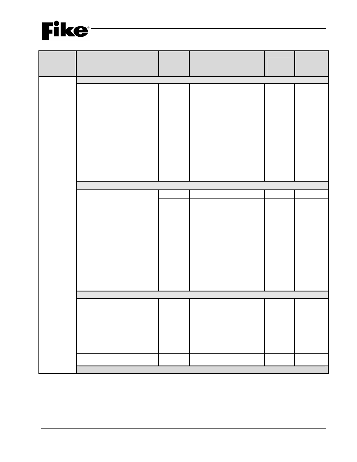
2.2 SOFTWARE PROGRAMMING FEATURES
The following tables identify the configurable features that can be changed by using the panel’s programming
software C-Linx. The table also identifies features that are available, but not permitted to be used per the
Cheetah Xi system’s UL listing.
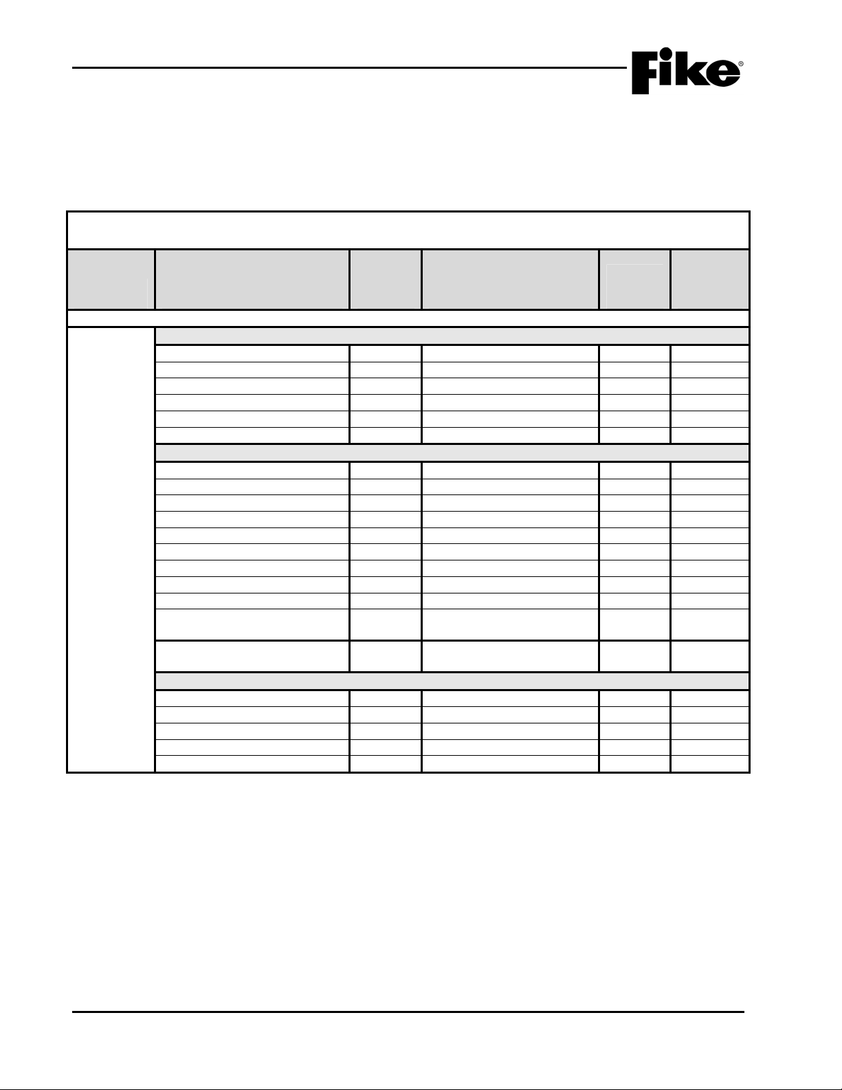
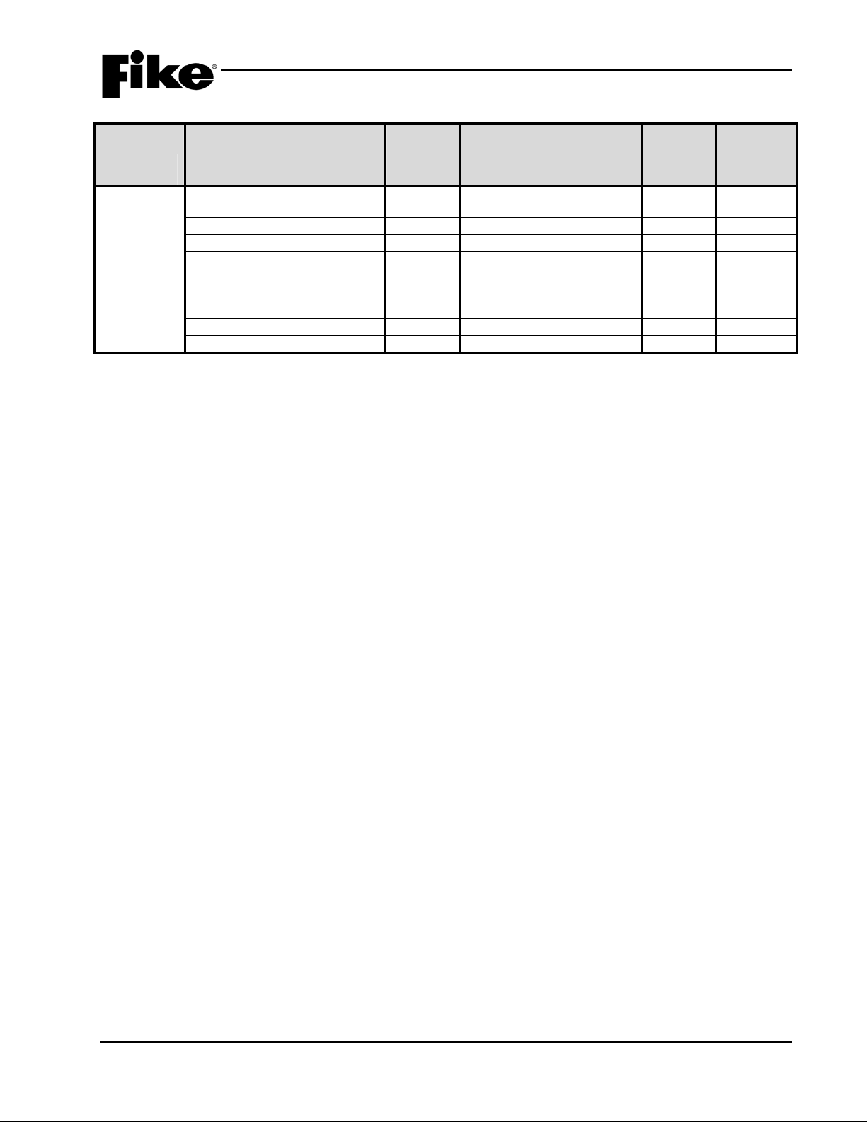
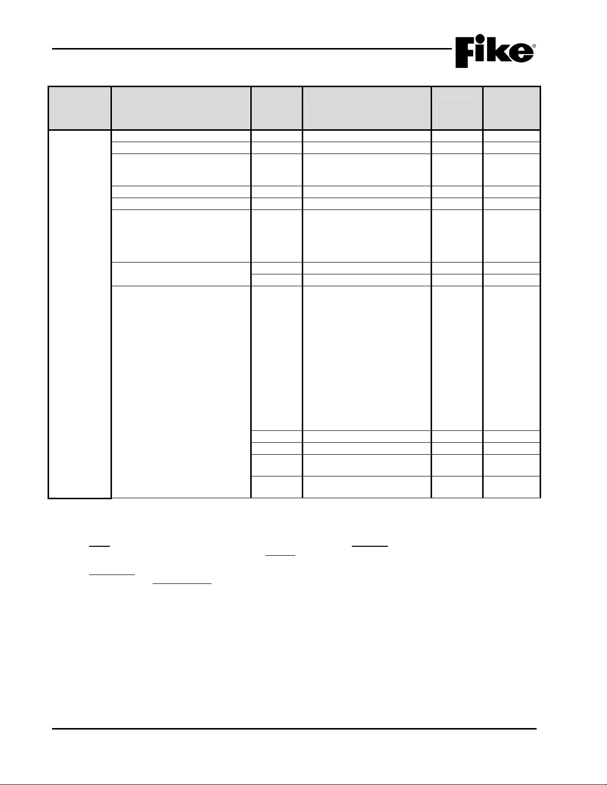
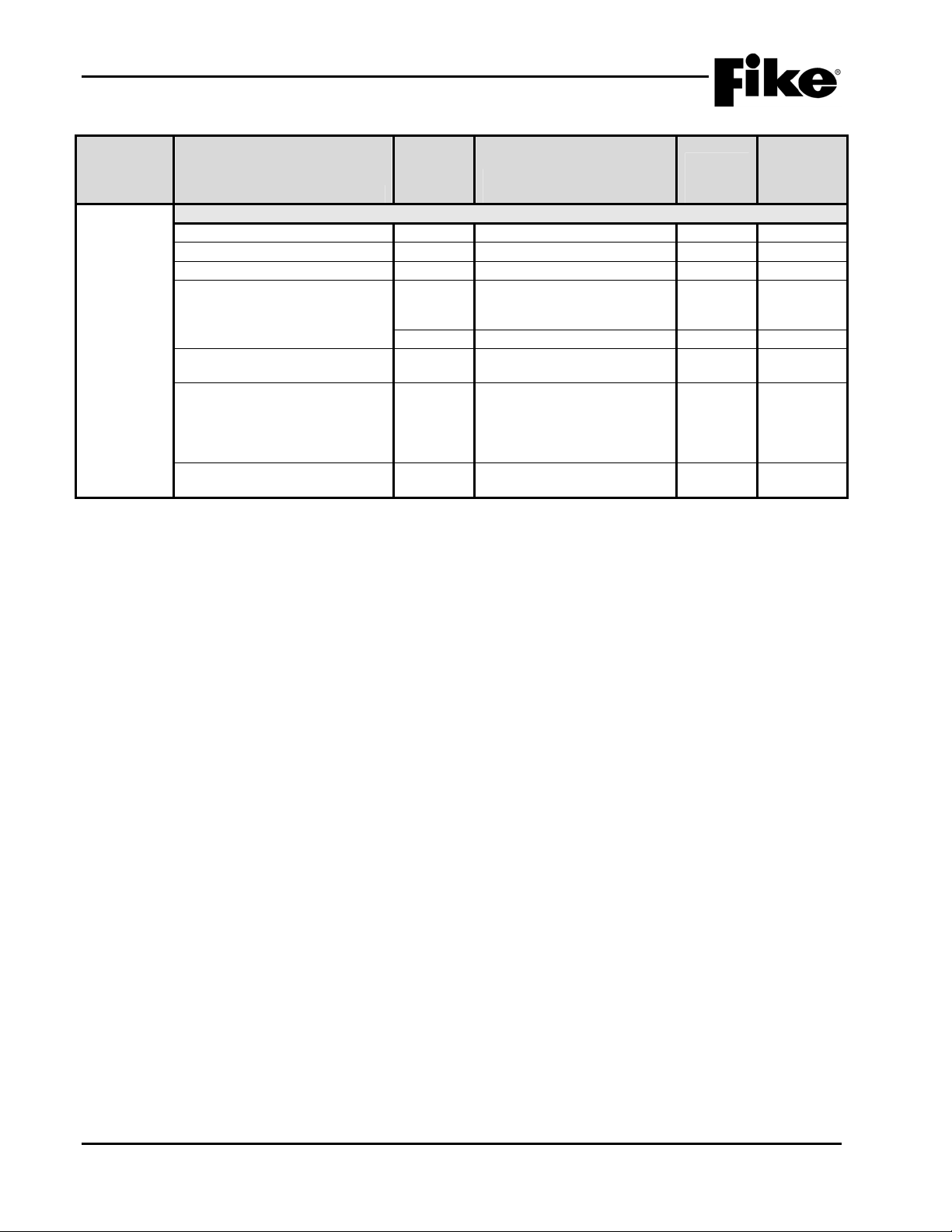
Exhibit 2-1: Programming Features
NOTICE TO USERS, INSTALLERS, AUTHORITIES HAVING JURISDICTION, AND OTHER INVOLVED PARTIES
This product incorporates field-programmable software. In order for the product to comply with the requirements in the Standard for Control Units and Accessories for
Circuit or
Component Program Feature or Option
Main Board Configuration Options
MISC.
Notes:
1. City of Chicago does not allow use of Drill, Silence and Acknowledge switches.
2. Can only be changed with Factory Level password. Level 2 required for use with solenoids
3. Level 2 ground fault detection required for use with solenoids.
4. If device on SLC has an internal error then the panel produces a trouble state (Enabled) and does not just logs it (Disabled).
5. An audible signal that has been silenced at the protected premises shall automatically resound and remain energized until
Fire Alarm Systems, UL 864, certain programming features or options must be limited to specific values or not used at all as indicat ed below.
Permitted
in UL
864?
(Y/N)
Possible Settings
(Defaults shown bold)
Settings
permitted
in UL 864 Notes
Miscellaneous Options
AC Trouble Delay Y
Abort Type N
Fan Restart Y
Drill/Silence/Acknowledge N
Auto Message Y
Walktest Y
0-30 hours, (Default 2)
1 – 6 (Default 2)
Automatic/Manual
Enabled / Disabled
Enabled / Disabled
Enabled / Disabled
1–3
1-4
Enabled 1,2
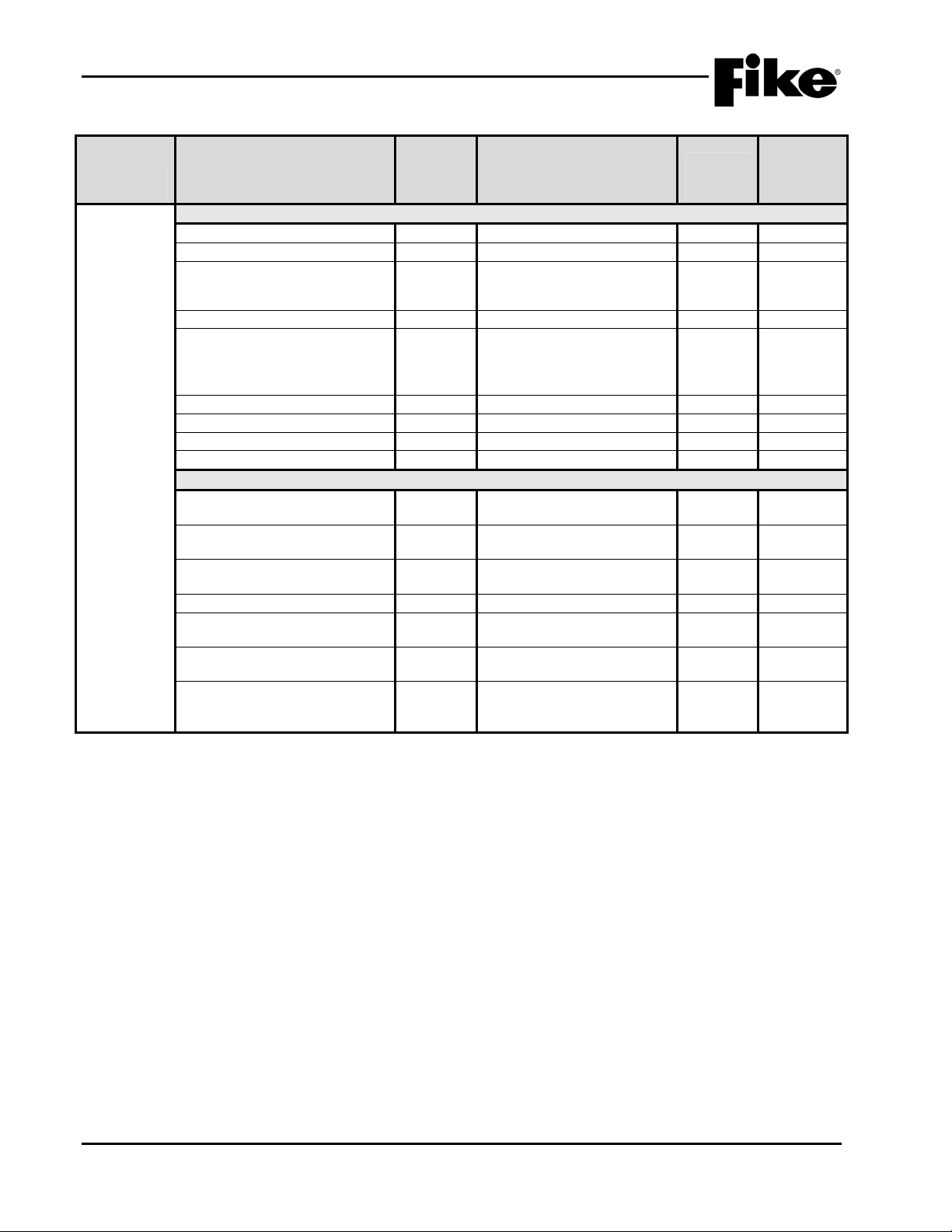
Supervision Options
Transformer Y
Loop Style (SLC) Y
Ground Fault Level 1 N
Ground Fault Level 2 N
Main Battery N
Auxiliary Battery N
Auxiliary Loop Module Present Y
Auxiliary Power Module Present Y
Eclipse Device Error Trouble Y
AHU Fire Dept Key Required for
Y
120VAC / 240VAC
4,6, or 7 (A, B, or X)
Enabled / Disabled
Enabled / Disabled
Supervised / Unsupervised
Supervised / Unsupervised
Enabled / Disabled
Enabled / Disabled
Enabled / Disabled
Yes / No
Enabled 2
Enabled 2, 3
Super.
Super.
Yes 4
AHU Restart
Battery Cutoff Y Loop # and Address #
(L: 1-4 Address: 0-254)
Silence Options
Unsilence Time Y
Silence Reminder Y
Silence Inhibit Y
Positive Alarm Sequence Y
Silence Mode Y
(i.e. Checksum Error)
silenced and retransmitted the signal to any supervising station to which the original signal was transmitted, as applicable, at
least once every 24 hours until the condition is corrected and the product is restored to the normal supervisory condition.
1-24 hours
Enabled / Disabled
Enabled / Disabled
Enabled / Disabled
UL
5
2-2 Cheetah Xi Programming Manual
Rev 1, 09/2013 P/N: 06-651
2.0 C-Linx PROGRAMMING OPTIONS
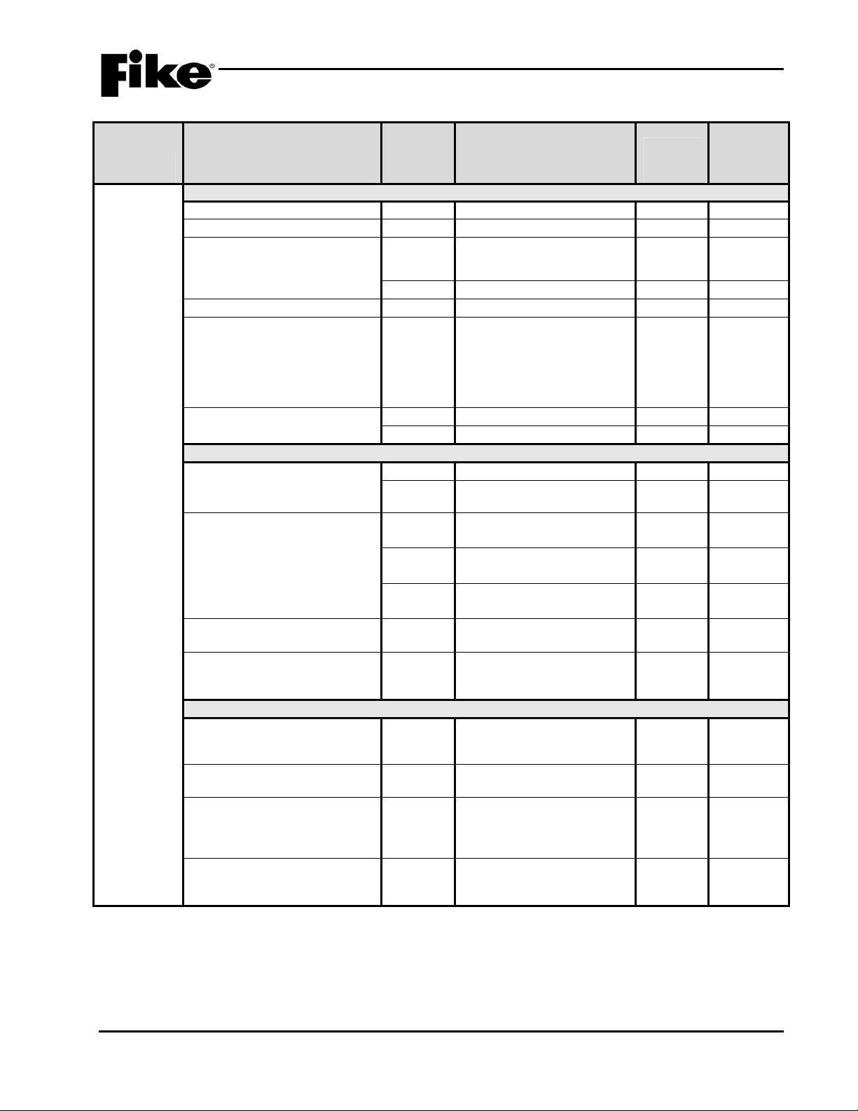
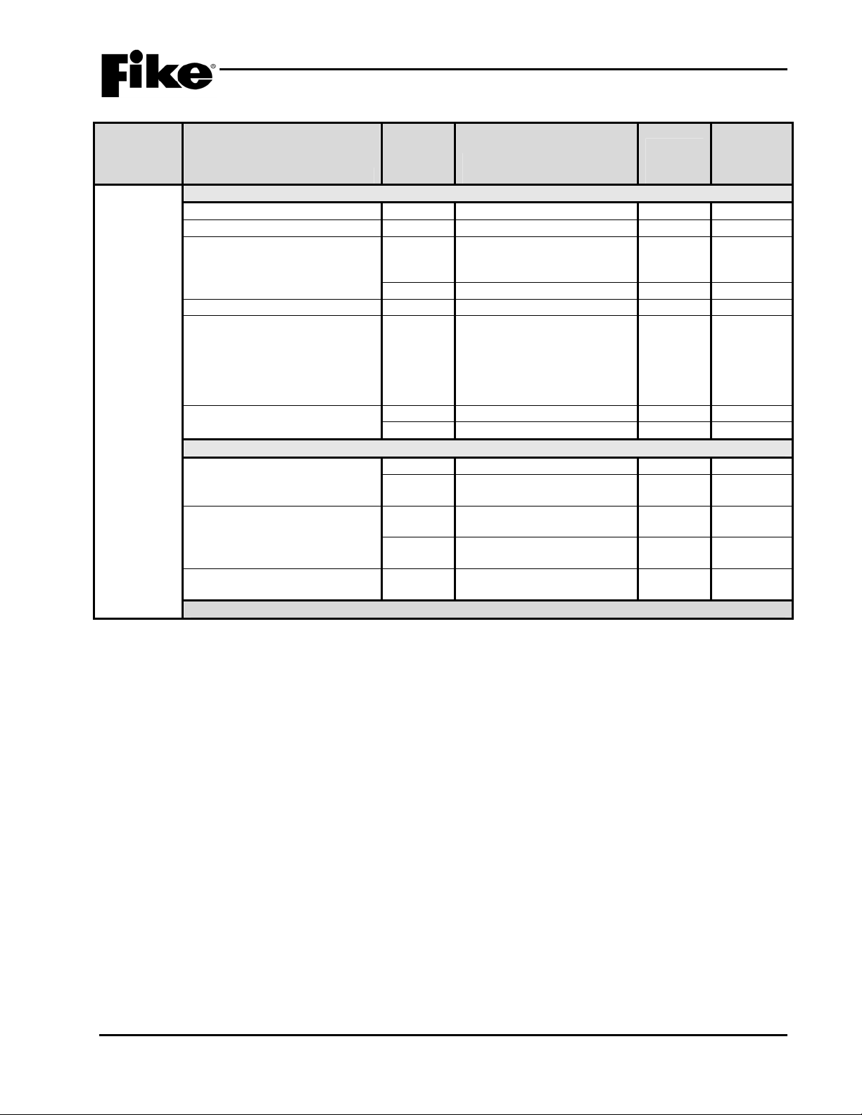
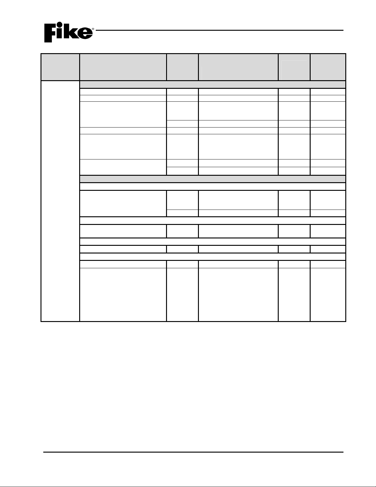
Exhibit 2-2: Programming Features Cont.
Permitted
in UL
Circuit or
Component Program Feature or Option
Time
Functions
Alarm Sensitivity Changes
Daytime Sensitivities start/stop Y 12:00 AM – 12:00 AM
864?
(Y/N)
Possible Settings
(Defaults shown bold)
Days that use daytime sensitivity Y Sunday – Saturday
Use Daylight Savings Time Y
Enabled / Disabled
Holiday Schedule
Night time sensitivity Y 20 days total (mm/dd/yyyy) 3
DACT Auto Test
DACT Auto test start hour Y
DACT Auto test period (hrs.) Y
0 – 23 (2 default)
0 - 24
NAC P10 and P11 (NAC 1 & NAC 2)
Sync Protocol Y
NO / Gentex / System
Sensor / Wheelock
State (Activation) Y
Alarm / Pre-Alarm 1 / PreAlarm 2 / Supervisory /
Trouble / Process / Release /
Pre-discharge
Silenceable Y
Silenceable / Non
silenceable
Zone Assignment Y
Circuit Y
Drill Y
Walktest Y
Non-Silence for Waterflow
Y
1 – 254
Enabled / Disabled
Enabled / Disabled
Enabled / Disabled
Enabled / Disabled
Activation
Panel Sync Protocol Y
Gentex / System Sensor /
Wheelock
Relays
P2 Main Board Relay
Relay Selection Y
State (Activation) Y
R1 / R2
Alarm / Pre-Al arm 1 / Pre-
Alarm 2 / Supervisory /
Trouble / Process / Zone
Disable / Release / Pre-
discharge / Abort
Silenceable Y
Non-Silenceable /
Silenceable
Relay Y
Zone Assignment Y
Drill Y
Notes:
1. If synchronization is selected, both NAC circuits will use the same sync protocol.
2. Refer to Fike document 06-186 for compatible notification appliances.
3. Only allows the installer to assign the night time sensitivity to a different obscuration level than during normal working hours.
No other functions are effected or disabled
4. Allows on board relays to be configured from the default setting of Alarm for R1 and Supervisory for R2 to the states listed in
State (Activation)
Enabled / Disabled
1 – 254
Enabled / Disabled
Settings
permitted
in UL 864 Notes
1,2
4
Cheetah Xi Programming Manual 2-3
P/N: 06-651 Rev 1, 09/2013
2.0 C-Linx PROGRAMMING OPTIONS
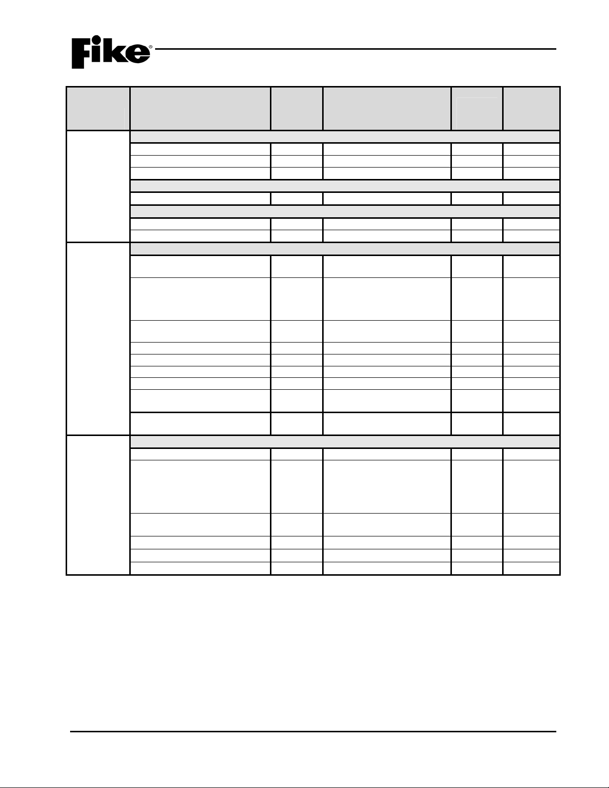
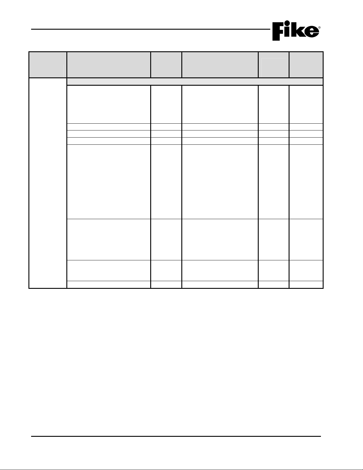
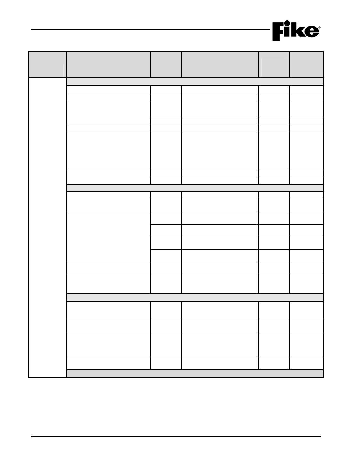
Exhibit 2-3: Programming Features Cont.
Permitted
in UL
Circuit or
Component Program Feature or Option
Relays
Zones Zones Y
P12
Relay Selection Y A / B / C / D
Module Y
State Y Alarm / Pre-Alarm 1 / Pre-
Restart Delay Y
Silenceable Y
Zone Assignment Y
Relay Y
Drill Y
P13
Relay Selection Y A / B / C / D
Module Y
State Y Alarm / Pre-Alarm 1 / Pre-
Restart Delay Y
Silenceable Y
Zone Assignment Y
Relay Y
Drill Y
Type Y
Custom Message Y 20 character user defined
Automatic Countdown Y
Manual Countdown Y
Zone Enabled Y
Zone Chimes Y Assign chime code to zones
864?
(Y/N)
No Module Installed / CRM4 /
CRPM (Opt 1) / CRPM (Opt
2) / Fire Communicator
Alarm 2 / Supervisory /
Trouble / Process / Zone
Disable / Release / Predischarge / Abort
0 – 250 (sec)
Non-Silenceable /
Silenceable
1 – 254
Enabled / Disabled
Enabled / Disabled
No Module Installed / CRM4 /
CRPM (Opt 1) / CRPM (Opt
2) / Network Interface Card
Alarm 2 / Supervisory /
Trouble / Process / Zone
Disable / Release / Predischarge / Abort
0 – 250 (sec)
Non-Silenceable /
Silenceable
1 – 254
Enabled / Disabled
Enabled / Disabled
1 – 254
Alarm Zone / Count Zone /
Cross Zone / Single Sensor
Release Zone
0 – 255 (30)
0 – 30 (15)
Enabled / Disabled
Possible Settings
(Defaults shown bold)
Settings
permitted
in UL 864 Notes
2-4 Cheetah Xi Programming Manual
Rev 1, 09/2013 P/N: 06-651
2.0 C-Linx PROGRAMMING OPTIONS
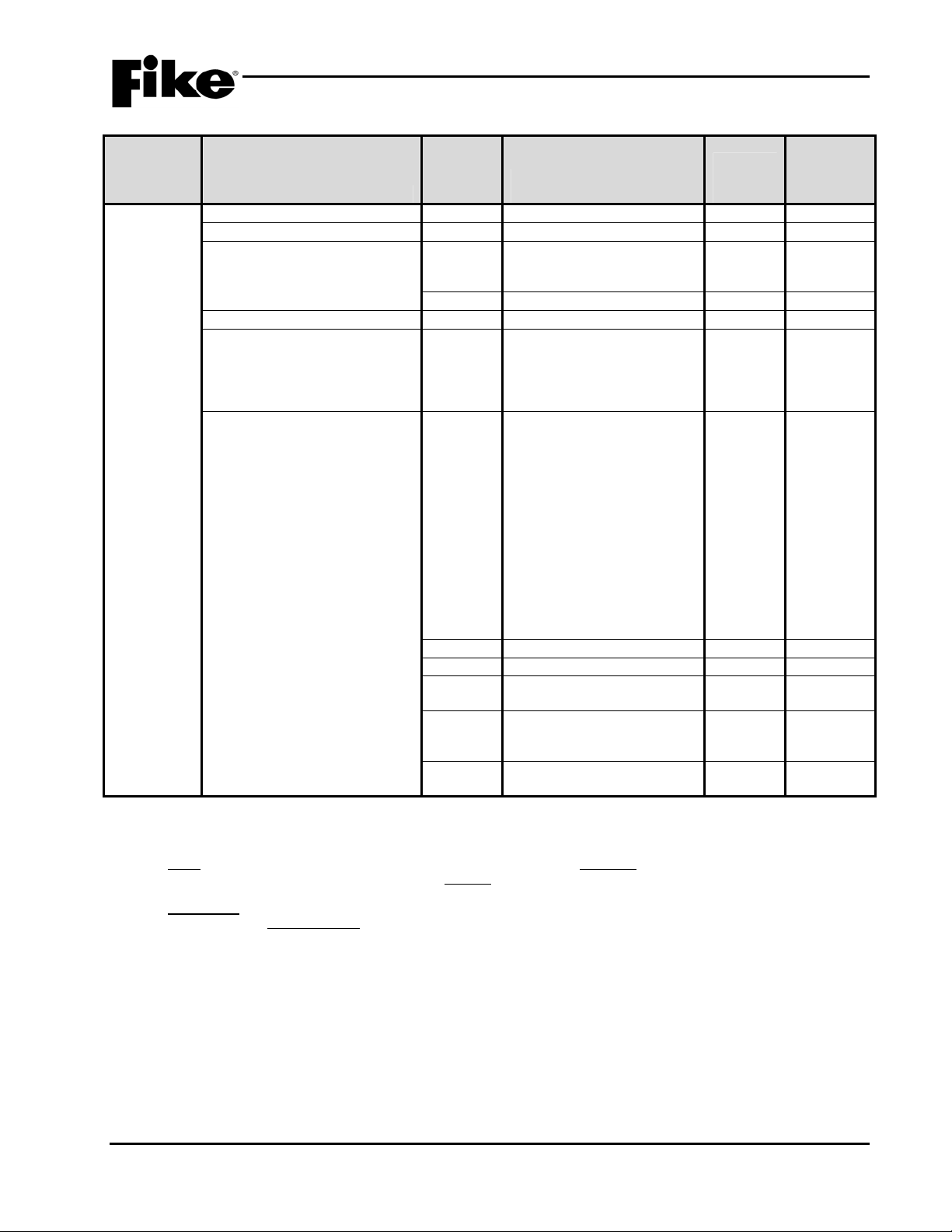
Exhibit 2-4: Programming Features Cont.
Permitted
in UL
Circuit or
Component Program Feature or Option
864?
(Y/N)
Possible Settings
(Defaults shown bold)
Peripherals Message Y 20 character user defined
(PERIPHERAL ID 02)
Zone Assignment Y
Supervision Y
Voice Y
Status Y
History Transmit Y
History Packing Y
History Message Y
Dual Channel Voice Y
Notes:
1. Peripheral device must be added to the Peripherals list before these configuration options are available.
2. This command contains status for Alarm, Supervisory, Trouble and all other states. Peripheral devices that have firmware
version before 3.00 should set this variable to STD, which is the original Cheetah Xi format. The ESP selection refers to an
“Expanded” format. Peripheral devices with 3.00 firmware or newer will used this command. The EXP setting speeds up
operation of the peripheral bus.
3. If set to COMPACT, a message filter within the panel is used to prevent transmission of certain history record events, including
the NEW DEVICE history messages. This is done so that the peripherals do not display messages that are not required. If set
to VERBOSE, all history messages are transmitted.
4. HISTORY PACKING refers to how many history records are transmitted back-to-back with minimum time in between. If set to
UNPACKED, history records are sent one at a time. If set to PACKED, up to 50 history records are sent back-to-back. This
will speed up transmission of large amounts of history data.
5. HISTORY MESSAGE refers to what kind of data is packed into the history command. If set to STD (standard), data is packed
as with previous versions. If set to EXP (expanded), both lines 1 and 2 of the history data as shown on the LCD of the panel is
packed into the history command.
0 - 254
Unsupervised / Supervised
No Voice / EVAX / Fike
STD / EXP
Compact / Verbose
Unpacked / Packed
STD / EXP
Enabled / Disabled
Settings
permitted
in UL 864 Notes
1
1
1
2
3
4
5
Cheetah Xi Programming Manual 2-5
P/N: 06-651 Rev 1, 09/2013
2.0 C-Linx PROGRAMMING OPTIONS
Exhibit 2-5: Programming Features Cont.
Permitted
Circuit or
Component Program Feature or Option
Network
Network Settings
Network Address (Panel ID) Y
Network Module Type Y
Network Panel Message Y 20 character user defined
in UL
864?
(Y/N)
Possible Settings
(Defaults shown bold)
1 - 128
None / First / Middle / Last
(CUSTOM MSG PANEL 001)
Settings
permitted
in UL 864 Notes
1
where ZZZ = zone number
Network Switch Operation Y
Network Switch IDs Y
Global / Local
1 – 128
2
Selects which network
devices the panel will receive
switch commands from.
Network Zones Y 1 – 254 3
Panel Supervision Y 1 – 254 4
Wiring Style Y
History Y
Style 4 / Style 7
Single / Multiple
Ethernet Settings
Source IP Address Y
000.000.000.000
5
User Defined
Destination IP Address Y
000.000.000.000
6
User Defined
Supervision IP Address Y
000.000.000.000
7
User Defined
Panel IP Supervision Y
History Transmits Y
000.000.000.000
1 – 10
4
(Fike recommends 2)
Supervision Timeout Y 1 – 59 (Sec., Min., Hour)
4 min. default
IP Time Y
IP Time Disabled
8
Accept IP Time
Send IP Time
Notes:
1. Defines the location of the panel with respect to others on the network.
2. Defines if the respective panel will react to Reset, Silence, Acknowledge, and Drill commands received from other networked
panels.
3. Defines which network zones will participate in the local panel zone(s).
4. Defines which network panel(s) the selected panel should supervise.
5. Defines the unique Internet Protocol (IP) address for the selected panel.
6. Defines the unique Internet Protocol (IP) address for the panel that is to receive history events from the selected panel.
7. Defines the unique Internet Protocol (IP) address for the panel that is to supervision responses from the selected panel.
8. Used to synchronize panel time over the network.
2-6 Cheetah Xi Programming Manual
Rev 1, 09/2013 P/N: 06-651
2.0 C-Linx PROGRAMMING OPTIONS
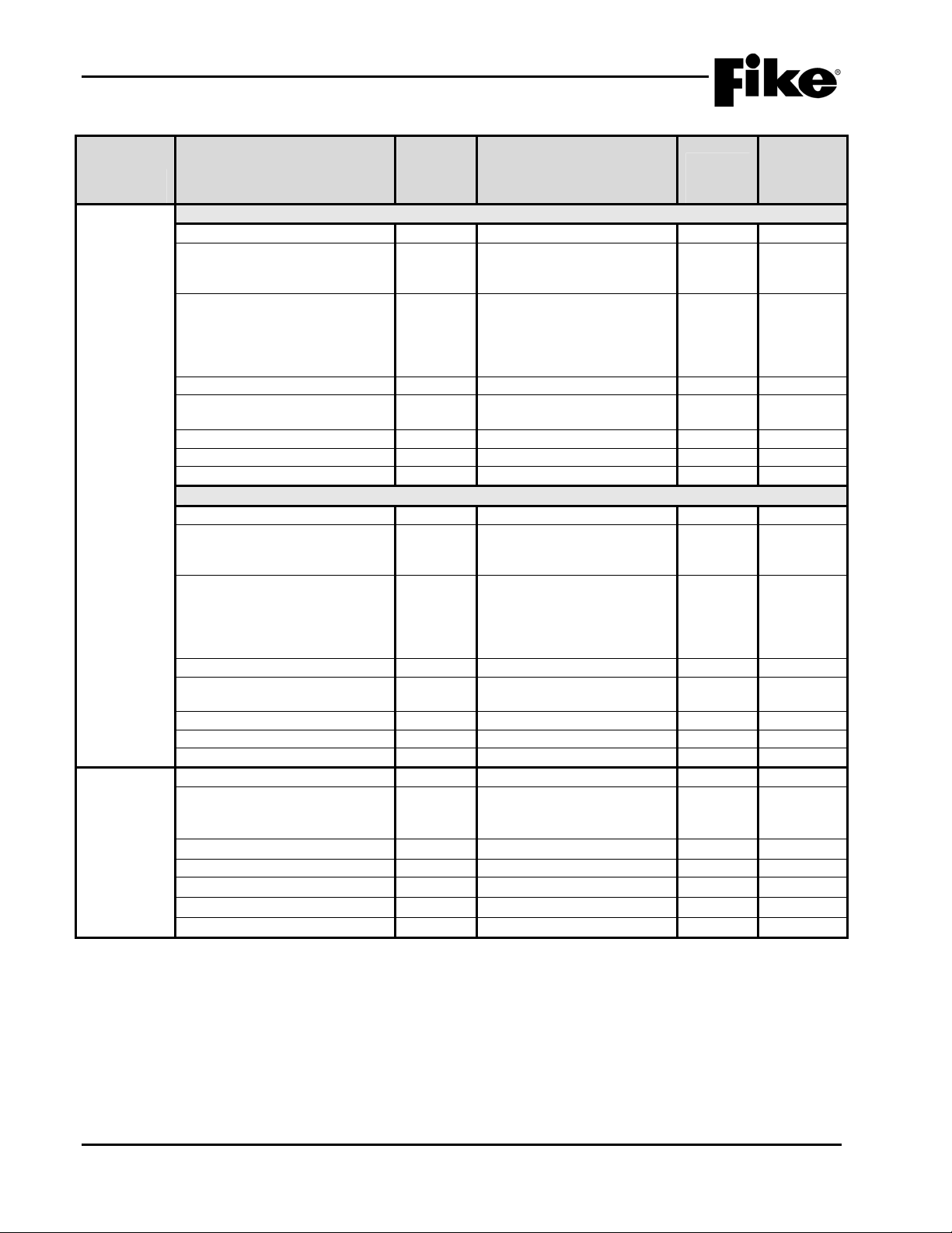
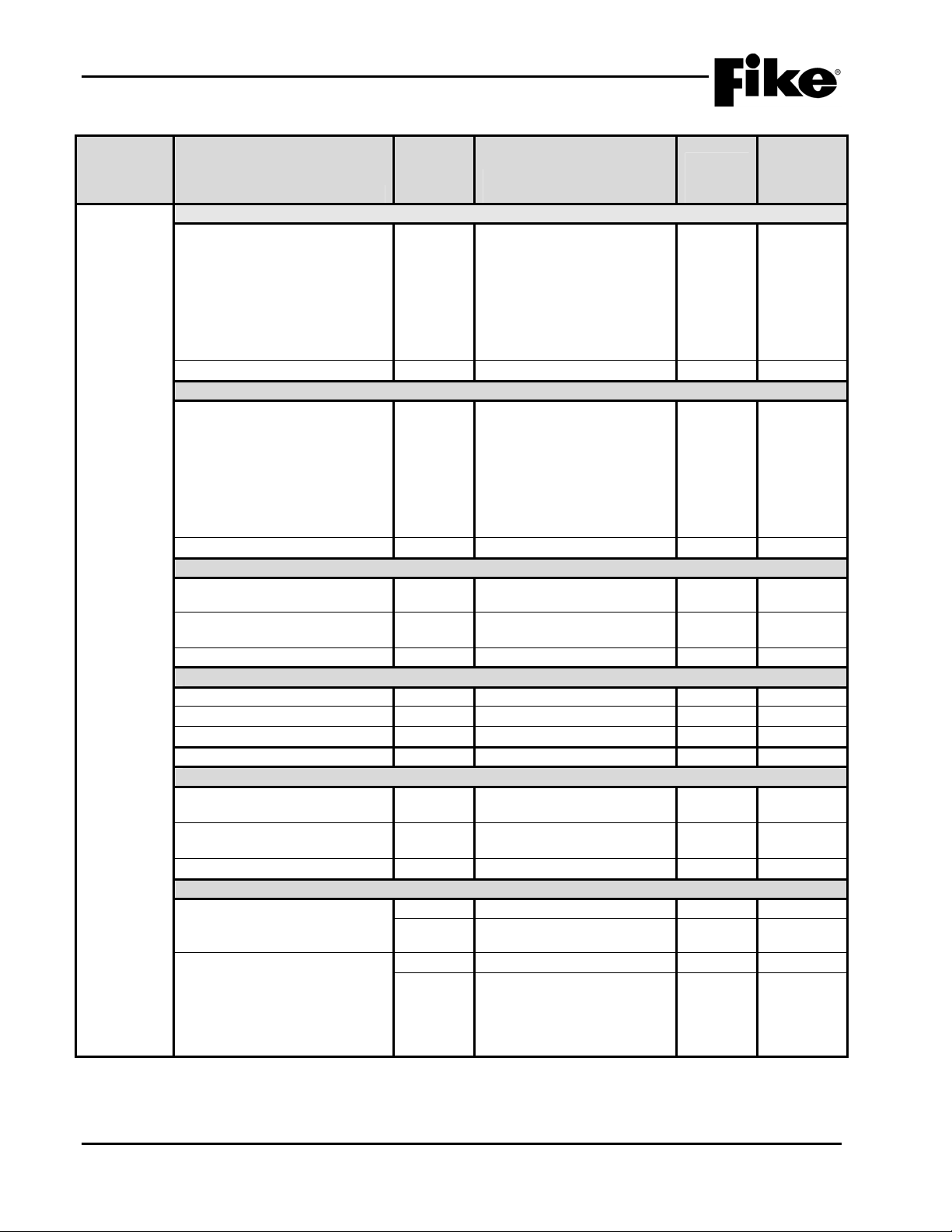
Exhibit 2-6: Programming Features Cont.
Permitted
in UL
Circuit or
Component Program Feature or Option
Defaults
(Photo
Sensor)
Common
Loop Number of Device Y
Address of Device Y
Custom Message Y 60 character user defined
Zone Assignments Y
Predischarge Type Y Auto Assign From 1st Zone /
Alarm Verification Y Time: 0 – 60 seconds
Sensitivity
Pre-Alarm 1 & 2 Levels Y
Alarm Levels Y
Drift Compensation
(Warning/Trouble)
Walktest Y
Device Summing
Broadcast Thresholds for
Summing (%OBS)
Summing Activation Level
(%OBS)
Summing Broadcast State N
Summing Addresses N 1 – 8 (Device addresses to
Notes:
1. Cheetah Xi can have up to four (4) addressable loops.
2. Can be assigned to 4 discrete zones, 2 zone ranges or 1 range and 2 discrete zones.
3. Pre-Alarm 2 setting must always be set equal or higher than Pre-Alarm 1 setting.
4. High setting must be equal or lower obscuration setting than Low setting.
5. Can be set in 1% increments. Trouble must be higher % than Warning.
864?
(Y/N)
Possible Settings
(Defaults shown bold)
1 - 4
1 – 254
(1-001 PHOTO DETECT
Loop 1 - Address 001)
Y
Default / User Defined
1 – 254
Alarm Only Device / 1st
Cross Zone Device / 2
Cross Zone Device / Count
Zone Device / Single
Release Device
Y
Enabled / Disabled
Enabled / Disabled
Y
0.5%/ft. – 4.0%/ft.
(0.1%/ft. increments)
Acclimate: 1.3%/ft. – 3.6%/ft.
(High 2.0% - Low 2.5%)
Y
Day/Night: 1.3%/ft. – 3.6%/ft.
(Day 3.6% - Night 3.6%)
Y
Alarm / Supervisory /
Supervisory NL
Y 50 – 100%
Warning 80%/Trouble 100%
Walktest at Alarm Level /
Walktest with IR / Walktest at
1.3%
N
Enabled / Disabled
(8 levels 0.5%/ft. – 4.0%/ft. in
0.1%/ft. increments)
N 1.0 – 10%/ft.
(0.5%/ft. increments)
Disabled / Alarm / Summing
Alarm / Supervisory Latching
/ Supervisory Non-Latching /
Pre-Alarm 1 / Pre-Alarm 2
participate in summing
group)
Settings
permitted
in UL 864 Notes
1
2
nd
3
4
5
Cheetah Xi Programming Manual 2-7
P/N: 06-651 Rev 1, 09/2013
2.0 C-Linx PROGRAMMING OPTIONS
Exhibit 2-7: Programming Features Cont.
Permitted
Circuit or
Component Program Feature or Option
Defaults
(Photo
Sensor)
Remote Annunciator
Annunciator Type Y
Silenceable Y
Positive Alarm Sequence (PAS) Y
Output Settings – Priority Row Y 1 – 8 1
Activation State Y
Action Type Y No Action / Activate on
in UL
864?
(Y/N)
Possible Settings
(Defaults shown bold)
None / Remote LED –
Follows Red / Remote LED –
Follows Green / Remote LED
– Follows Amber / Remote
LED – Independent /
Sounder Base / Relay Base
Silenceable / Non- Silence
Disabled / Enabled
No State / Alarm / Summing
Alarm / Test Alarm / Alarm
Verification ON / Pre-Alarm 1
/ Pre-Alarm 2 / Supervisory /
Trouble / Open Circuit
Trouble / Short Circuit
Trouble / Low Power Trouble
/ Maintenance Trouble /
Process / Zone Disable
Switch / Release / PreDischarge / Abort / Release
Ckt. Trouble
Settings
permitted
in UL 864 Notes
1,2
2
2
Any of 3 zones / Activate
on All of 3 zones / Activate
on Specific Device /
Activate on multiple
priority rows active
Output Pattern Y OFF / ON Continuous /
Slow / Fast / Temporal /
Walktest / Alert / Action
State Counter Y 1 – 16
Notes:
1. If annunciator type is set to Independent Operation, Sounder Base, or Relay Base an 8-row priority table will be displayed.
Table values are set using the Output Settings fields.
2. If annunciator type is set to Sounder Base, Silence and Positive Alarm Sequence (PAS) options will be displayed.
2-8 Cheetah Xi Programming Manual
Rev 1, 09/2013 P/N: 06-651
2.0 C-Linx PROGRAMMING OPTIONS
Exhibit 2-8: Programming Features Cont.
Permitted
in UL
Circuit or
Component Program Feature or Option
Defaults
(Photo/Heat
Sensor)
Common
Loop Number of Device Y
Address of Device Y
Custom Message Y
Zone Assignments Y
Predischarge Type Y Auto Assign From 1st Zone /
Alarm Verification Y
Sensitivity
Pre-Alarm 1 & 2 Levels Y
Alarm Levels Y
Flame Enhance N
Drift Compensation
(Warning/Trouble)
Walktest Y
Device Summing
Broadcast Thresholds for
Summing (%OBS)
Summing Activation Level
(%OBS)
Summing Broadcast State N
Summing Addresses N
Remote Annunciator (See Exhibit 2-7 for programming features)
Notes:
1. Cheetah Xi can have up to four (4) addressable loops.
2. Can be assigned to 4 discrete zones, 2 zone ranges or 1 range and 2 discrete zones.
3. Pre-Alarm 2 setting must always be set equal or higher than Pre-Alarm 1 setting.
4. High setting must be equal or lower obscuration setting than Low setting.
5. Can be set in 1% increments. Trouble must be higher % than Warning.
864?
(Y/N)
Y
Y
Y
Y
Y
Y
N
N
Possible Settings
(Defaults shown bold)
1 - 4
1 – 254
60 character user defined
(1-001 PHO/HT DETECT
Loop 1 - Address 001)
Default / User Defined
1 – 254
Alarm Only Device / 1
Cross Zone Device / 2nd
Cross Zone Device / Count
Zone Device / Single
Release Device
Time: 0 – 60 seconds
Enabled / Disabled
Enabled / Disabled
0.5%/ft. – 4.0%/ft.
(0.1%/ft. increments)
Acclimate: 1.3%/ft. – 3.6%/ft.
(High 2.0% - Low 2.5%)
Day/Night: 1.3%/ft. – 3.6%/ft.
(Day 3.6% - Night 3.6%)
Alarm / Supervisory /
Supervisory NL
ON / OFF
50 – 100%
Warning 80%/Trouble 100%
Walktest at Alarm Level /
Walktest with IR / Walktest at
1.3%
Enabled / Disabled
(8 levels 0.5%/ft. – 4.0%/ft. in
0.1%/ft. increments)
1.0 – 10%/ft.
(0.5%/ft. increments)
Disabled / Alarm / Summing
Alarm / Supervisory Latching /
Supervisory Non-Latching /
Pre-Alarm 1 / Pre-Alarm 2
1 – 8 (Device addresses to
participate in summing group)
Settings
permitted
in UL 864 Notes
1
2
st
3
4
5
Cheetah Xi Programming Manual 2-9
P/N: 06-651 Rev 1, 09/2013

2.0 C-Linx PROGRAMMING OPTIONS
Exhibit 2-9: Programming Features Cont.
Permitted
in UL
Circuit or
Component Program Feature or Option
Defaults
(Photo/Duct
Sensor)
Common
Loop Number of Device Y
Address of Device Y
Custom Message Y 60 character user defined
Zone Assignments Y
Predischarge Type Y Auto Assign From 1st Zone /
Alarm Verification Y Time: 0 – 60 seconds
Sensitivity
Pre-Alarm 1 & 2 Levels Y
Alarm Levels Y
Drift Compensation
(Warning/Trouble)
Walktest Y
Device Summing
Broadcast Thresholds for
Summing (%OBS)
Summing Activation Level
(%OBS)
Summing Broadcast State N
Summing Addresses N 1 – 8 (Device addresses to
Remote Annunciator (See Exhibit 2-7 for programming features)
Notes:
1. Cheetah Xi can have up to four (4) addressable loops.
2. Can be assigned to 4 discrete zones, 2 zone ranges or 1 range and 2 discrete zones.
3. Pre-Alarm 2 setting must always be set equal or higher than Pre-Alarm 1 setting.
4. High setting must be equal or lower obscuration setting than Low setting.
5. Can be set in 1% increments. Trouble must be higher % than Warning.
864?
(Y/N)
Possible Settings
(Defaults shown bold)
1 - 4
1 – 254
(1-001 DUCT DETECT
Loop 1 - Address 001)
Y
Default / User Defined
1 – 254
Alarm Only Device / 1
Cross Zone Device / 2
Cross Zone Device / Count
Zone Device / Single Release
Device
Y
Enabled / Disabled
Enabled / Disabled
Y
0.6%/ft. – 4.0%/ft.
(0.1%/ft. increments)
Acclimate: 0.8%/ft. – 3.4%/ft.
(High 2.0% - Low 2.5%)
Y
Day/Night: 0.8%/ft. – 3.4%/ft.
(Day 1.5% - Night 3.4%)
Y
Alarm / Supervisory /
Supervisory NL
Y 50 – 100%
Warning 80%/Trouble 100%
Walktest at Alarm Level /
Walktest with IR / Walktest at
1.3%
N
Enabled / Disabled
(8 levels 0.5%/ft. – 4.0%/ft. in
0.1%/ft. increments)
N 1.0 – 10%/ft.
(0.5%/ft. increments)
Disabled / Alarm / Summing
Alarm / Supervisory Latching
/ Supervisory Non-Latching /
Pre-Alarm 1 / Pre-Alarm 2
participate in summing group)
Settings
permitted
in UL 864 Notes
1
2
st
nd
3
4
5
2-10 Cheetah Xi Programming Manual
Rev 1, 09/2013 P/N: 06-651
2.0 C-Linx PROGRAMMING OPTIONS
Exhibit 2-10: Programming Features Cont.
Permitted
in UL
Circuit or
Component Program Feature or Option
Defaults
(Heat
Sensor)
Common
Loop Number of Device Y
Address of Device Y
864?
(Y/N)
Possible Settings
(Defaults shown bold)
1 - 4
1 – 254
Custom Message Y 60 character user defined
(1-001 HEAT DETECT
Loop 1 - Address 001)
Y
Zone Assignments Y
Predischarge Type Y Auto Assign From 1st Zone /
Default / User Defined
1 – 254
Alarm Only Device / 1
Cross Zone Device / 2
st
nd
Cross Zone Device / Count
Zone Device / Single Release
Device
Alarm Verification Y Time: 0 – 60 seconds
Y
Enabled / Disabled
Sensitivity
Pre-Alarm 1 & 2 Levels Y
Y
Enabled / Disabled
70°F - 190°F
(5°F increments)
Alarm Levels (Day/Night) Y
Fixed Temp: 135°F - 190°F
(5°F increments)
Y
Rate of Rise: 135°F - 174°F
(5°F increments)
Walktest Y
Walktest at 135°F / Walktest
with IR
Remote Annunciator (See Exhibit 2-7 for programming features)
Notes:
1. Cheetah Xi can have up to four (4) addressable loops.
2. Can be assigned to 4 discrete zones, 2 zone ranges or 1 range and 2 discrete zones.
3. Pre-Alarm 2 setting must always be set equal or higher than Pre-Alarm 1 setting.
4. Rate of Rise temperature range is 135°F - 174°F. Fixed temperature operation will be used for detection above this range.
Settings
permitted
in UL 864 Notes
1
2
3
4
4
Cheetah Xi Programming Manual 2-11
P/N: 06-651 Rev 1, 09/2013
2.0 C-Linx PROGRAMMING OPTIONS
Exhibit 2-11: Programming Features Cont.
Permitted
in UL
Circuit or
Component Program Feature or Option
Defaults
(Ion Sensor)
Common
Loop Number of Device Y
Address of Device Y
Custom Message Y
Zone Assignments Y
Predischarge Type Y Auto Assign From 1st Zone /
Alarm Verification Y
Sensitivity
Pre-Alarm 1 & 2 Levels Y
Alarm Levels Y
Drift Compensation Y
Walktest Y
Device Summing
Broadcast Thresholds for
Summing (%OBS)
Summing Activation Level
(%OBS)
Summing Broadcast State N
Summing Addresses N
Remote Annunciator (See Exhibit 2-7 for programming features)
Notes:
1. Cheetah Xi can have up to four (4) addressable loops.
2. Can be assigned to 4 discrete zones, 2 zone ranges or 1 range and 2 discrete zones.
3. Pre-Alarm 2 setting must always be set equal or higher than Pre-Alarm 1 setting.
4. High setting must be equal or lower obscuration setting than Low setting.
5. Can be set in 1% increments. Trouble must be higher % than Warning.
864?
(Y/N)
Y
Y
Y
Y
Y
N
N
N
Possible Settings
(Defaults shown bold)
1 - 4
1 – 254
60 character user defined
(1-001 ION DETECT
Loop 1 - Address 001)
Default/User Defined
1 – 254
Alarm Only Device / 1
Cross Zone Device / 2nd
Cross Zone Device / Count
Zone Device / Single
Release Device
Time: 0 – 60 seconds
Enabled / Disabled
Enabled / Disabled
100 – 40 Microns
(5 Micron increments)
Acclimate: 80 – 50 Microns
(5 Micron increments)
Day/Night: 80 – 50 Microns
(5 Micron increments)
Alarm / Supervisory /
Supervisory NL
Smolder Enhance Off /
Smolder Enhance On
50 – 100%
Warning 80%/Trouble 100%
Walktest at Alarm Level /
Walktest with IR / Walktest at
1.3%
Enabled / Disabled
(8 levels 0.5%/ft. – 4.0%/ft. in
0.1%/ft. increments)
1.0 – 10%/ft.
(0.5%/ft. increments)
Disabled / Alarm/Summing
Alarm / Supervisory Latching /
Supervisory Non-Latching /
Pre-Alarm 1 / Pre-Alarm 2
1 – 8 (Device addresses to
participate in summing group)
Settings
permitted
in UL 864 Notes
1
2
st
3
4
5
2-12 Cheetah Xi Programming Manual
Rev 1, 09/2013 P/N: 06-651
2.0 C-Linx PROGRAMMING OPTIONS
Exhibit 2-12: Programming Features Cont.
Permitted
Circuit or
Component Program Feature or Option
Defaults
(Monitor
Module)
Loop Number of Device Y
Address of Device Y
Custom Message Y 60 character user defined
in UL
864?
(Y/N)
Possible Settings
(Defaults shown bold)
1 - 4
1 – 254
Settings
permitted
in UL 864 Notes
1
(1-001 INPUT MANALRM
Loop 1 - Address 001)
Y
Zone Assignments Y
Predischarge Type Y
Default / User Defined
1 – 254
Alarm Device Only / 1
Cross Zone Device / 2
st
nd
2
6
Cross Zone Device / Count
Zone Device / Single Release
Device
Input Function Type Y
No Input Function /
ManAlarm / Detection/
Waterflow /Pre-Alarm 1 / PreAlarm 2 / Supervisory /
Trouble / Process / PAS
Inhibit / Reset / Silence /
Acknowledge / Drill / Zone
Disable / Fan Restart /
Smoke Control Confirmation /
Manual Alarm Stage 2 / AHU
Fire Dept Key / Manual
Release / Manual Release
with Countdown / Abort /
Watermist Activation
Y Verify Time: 0 – 255 seconds 3
Y
Y
Latching / Non-Latching
Normally Open / Normally
4
5
Closed
Y
Class B Contact / Class A
Latching / Class A Auto
Restore
Y
No Short Detection / Short
Detection
Notes:
1. Cheetah Xi can have up to four (4) addressable loops.
2. Can be assigned to 4 discrete zones, 2 zone ranges or 1 range and 2 discrete zones.
3. If monitor module function type is set to Detection or Watermist Activation, an alarm verification time can be set.
4. Either = Waterflow, PA1, PA2, Supervisory, Trouble, Process, PAS Inhibit; Non-Latch = Silence, Acknowledge, Drill, Zone
Disable, Fan Restart, Smoke Confirmation, Abort; Latching = ManAlarm, Detection, Reset, Manual Alarm Stage 2, Manual
Release, Manual Release with Countdown, Watermist.
5. NO Contacts = Detection, Manual Alarm, Reset, Manual Alarm Stage 2, Manual Release, Manual Release with Countdown,
Abort, Watermist; NO/NC Contacts = Waterflow, PA1, PA2, Supervisory, Trouble, Process, PAS Inhibit, Silence, Acknowledge,
Drill, Zone Disable, Fan Restart, Smoke Confirmation.
6. If monitor module function type is set to Detection, a Predischarge Type must be set.
Cheetah Xi Programming Manual 2-13
P/N: 06-651 Rev 1, 09/2013
2.0 C-Linx PROGRAMMING OPTIONS
Exhibit 2-13: Programming Features Cont.
Permitted
in UL
Circuit or
Component Program Feature or Option
Defaults
(Mini Monitor
Module)
Loop Number of Device Y
Address of Device Y
Custom Message Y 60 character user defined
864?
(Y/N)
Possible Settings
(Defaults shown bold)
1 - 4
1 – 254
(1-001 MINI MANALRM
Loop 1 - Address 001)
Custom Message Y
Zone Assignments Y
Predischarge Type Y
Default / User Defined
1 – 254
Alarm Device Only / 1
Cross Zone Device / 2
st
nd
Cross Zone Device / Count
Zone Device / Single Release
Device
Alarm Verification Y Time: 0 – 60 seconds
Y
Input Function Type Y
Enabled / Disabled
No Input Function /
ManAlarm / Detection/
Waterflow /Pre-Alarm 1 / PreAlarm 2 / Supervisory /
Trouble / Process / PAS
Inhibit / Reset / Silence /
Acknowledge / Drill / Zone
Disable / Fan Restart /
Smoke Control Confirmation /
Manual Alarm Stage 2 / AHU
Fire Dept Key /Manual
Release / Manual Release
with Countdown / Abort /
Watermist Activation
Y Verify Time: 0 – 255 seconds 3
Y
Y
Latching / Non-Latching
Normally Open / Normally
Closed
Y
No Short Detection / Short
Detection
Notes:
1. Cheetah Xi can have up to four (4) addressable loops.
2. Can be assigned to 4 discrete zones, 2 zone ranges or 1 range and 2 discrete zones.
3. If monitor module function type is set to Detection, an alarm verification time can be set.
4. Either = Waterflow, PA1, PA2, Supervisory, Trouble, Process, PAS Inhibit; Non-Latch = Silence, Acknowledge, Drill, Zone
Disable, Fan Restart, Smoke Confirmation, Abort; Latching = ManAlarm, Detection, Reset, Manual Alarm Stage 2, Manual
Release, Manual Release with Countdown, Watermist.
5. NO Contacts = Detection, Manual Alarm, Reset, Manual Alarm Stage 2, Manual Release, Manual Release with Countdown,
Abort, Watermist; NO/NC Contacts = Waterflow, PA1, PA2, Supervisory, Trouble, Process, PAS Inhibit, Silence, Acknowledge,
Drill, Zone Disable, Fan Restart, Smoke Confirmation.
6. If monitor module function type is set to Detection, a Predischarge Type must be set.
Settings
permitted
in UL 864 Notes
1
2
6
4
5
2-14 Cheetah Xi Programming Manual
Rev 1, 09/2013 P/N: 06-651
2.0 C-Linx PROGRAMMING OPTIONS
Exhibit 2-14: Programming Features Cont.
Permitted
in UL
Circuit or
Component Program Feature or Option
Defaults
(Pull Station
Module)
Loop Number of Device Y
Address of Device Y
Custom Message Y 60 character user defined
864?
(Y/N)
Possible Settings
(Defaults shown bold)
1 - 4
1 – 254
(1-001 PULL STATION
Loop 1 - Address 001)
Custom Message Y
Zone Assignments Y
Input Function Y
Default/User Defined
1 – 254
No Input Function / Manual
Alarm / Manual Release /
Manual Release with
Countdown
Notes:
1. Cheetah Xi can have up to four (4) addressable loops.
2. Can be assigned to 4 discrete zones, 2 zone ranges or 1 range and 2 discrete zones.
Settings
permitted
in UL 864 Notes
1
2
Cheetah Xi Programming Manual 2-15
P/N: 06-651 Rev 1, 09/2013
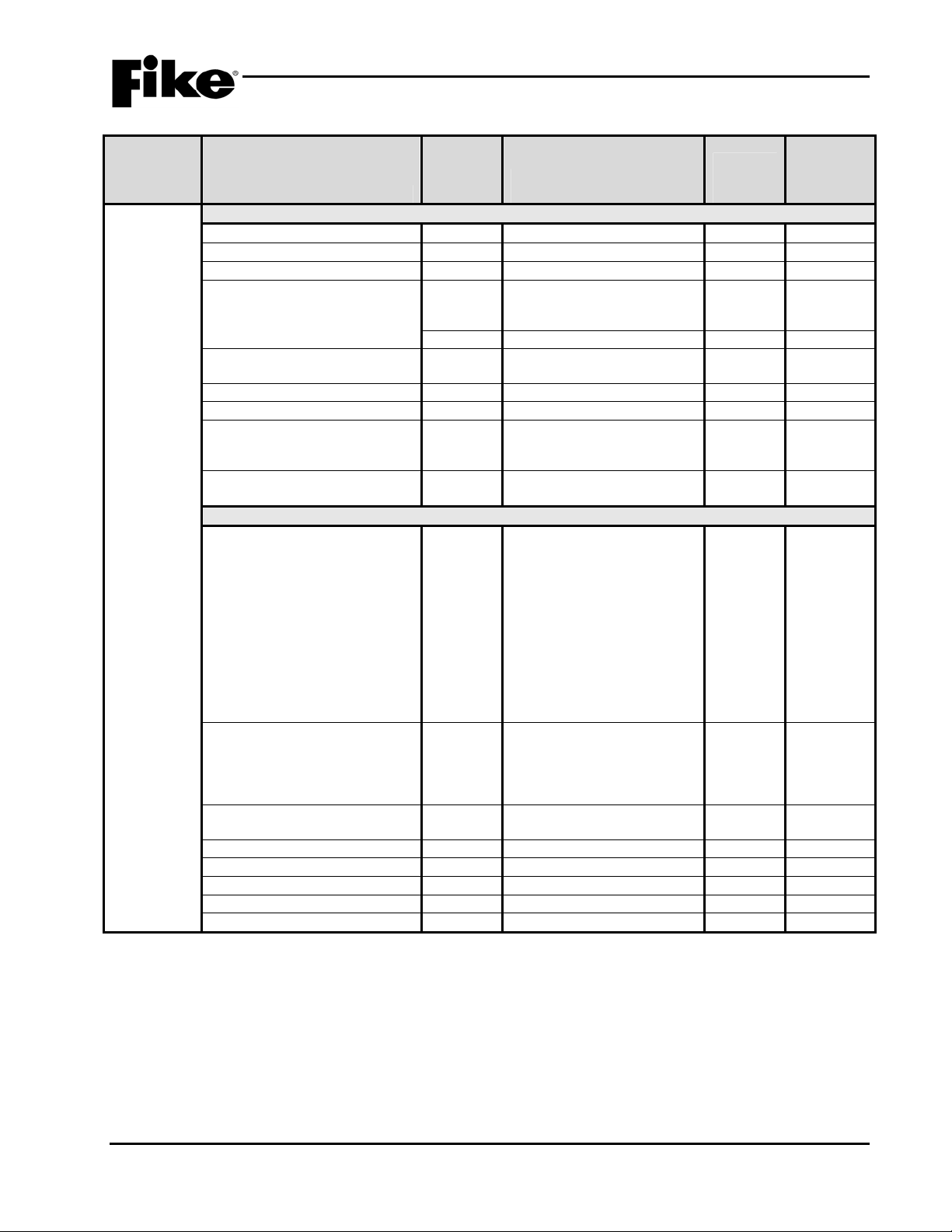
2.0 C-Linx PROGRAMMING OPTIONS
Exhibit 2-15: Programming Features Cont.
Permitted
in UL
Circuit or
Component Program Feature or Option
Defaults
(Supervised
Control
Module)
Common
Loop Number of Device Y
Address of Device Y
Output Y
Custom Message Y 60 character user defined
Custom Message Y
Zone Assignments
(device troubles)
Defaults for Pre-Action Y
Defaults for 2 Stage Alarm N
Drill Output Pattern Y
Output Silenceable Y
Positive Alarm Sequencing
(PAS)
Power Supply Monitor Y
Output Control
Activation State Y
Action Type Y
Output Pattern Y
Output Pattern Set Y
State Counter Y
Zone Assignments (activation) Y
Notes:
1. Cheetah Xi can have up to four (4) addressable loops.
2. Can be assigned to 4 discrete zones, 2 zone ranges or 1 range and 2 discrete zones.
3. Modifies control module configuration for use with Pre-Action solenoid.
4. If selected, the control module configuration will be modified for 2-Stage Alarm Operation (City of Chicago).
5. Can be assigned to any 3 zones, 254 any zone, or 255 any zone (non-disable).
864?
(Y/N)
Y
Y
Possible Settings
(Defaults shown bold)
1 - 4
1 – 254
Enabled/Disabled
(1-001 OUTPUT MODULE
Loop 1 - Address 001)
Default/User Defined
1 – 254
Yes/No
Yes/No
Drill Disabled / On
Continuous / Slow / Fast /
Temporal
Silenceable/Non-Silenceable
Enabled / Disabled
Enabled / Disabled
No State / Alarm / Summing
Alarm / Test Alarm / Alarm
Verification ON / Pre-Alarm 1
/ Pre-Alarm 2 / Supervisory /
Trouble / Open Circuit
Trouble / Short Circuit
Trouble / Low Power Trouble
/ Maintenance Trouble /
Process / Zone Disable
Switch / Release / PreDischarge / Abort / Release
Circuit Trouble
No Action / Activate on Any
of 3 zones / Activate on All of
3 zones / Activate on Specific
Device / Activate on multiple
priority rows active
OFF / ON Continuous / Slow
/ Fast / Temporal / Walktest /
Timed / Custom Defined
1 - 3
1 – 16
0 - 255
Settings
permitted
in UL 864 Notes
1
2
3
4
5
2-16 Cheetah Xi Programming Manual
Rev 1, 09/2013 P/N: 06-651
2.0 C-Linx PROGRAMMING OPTIONS
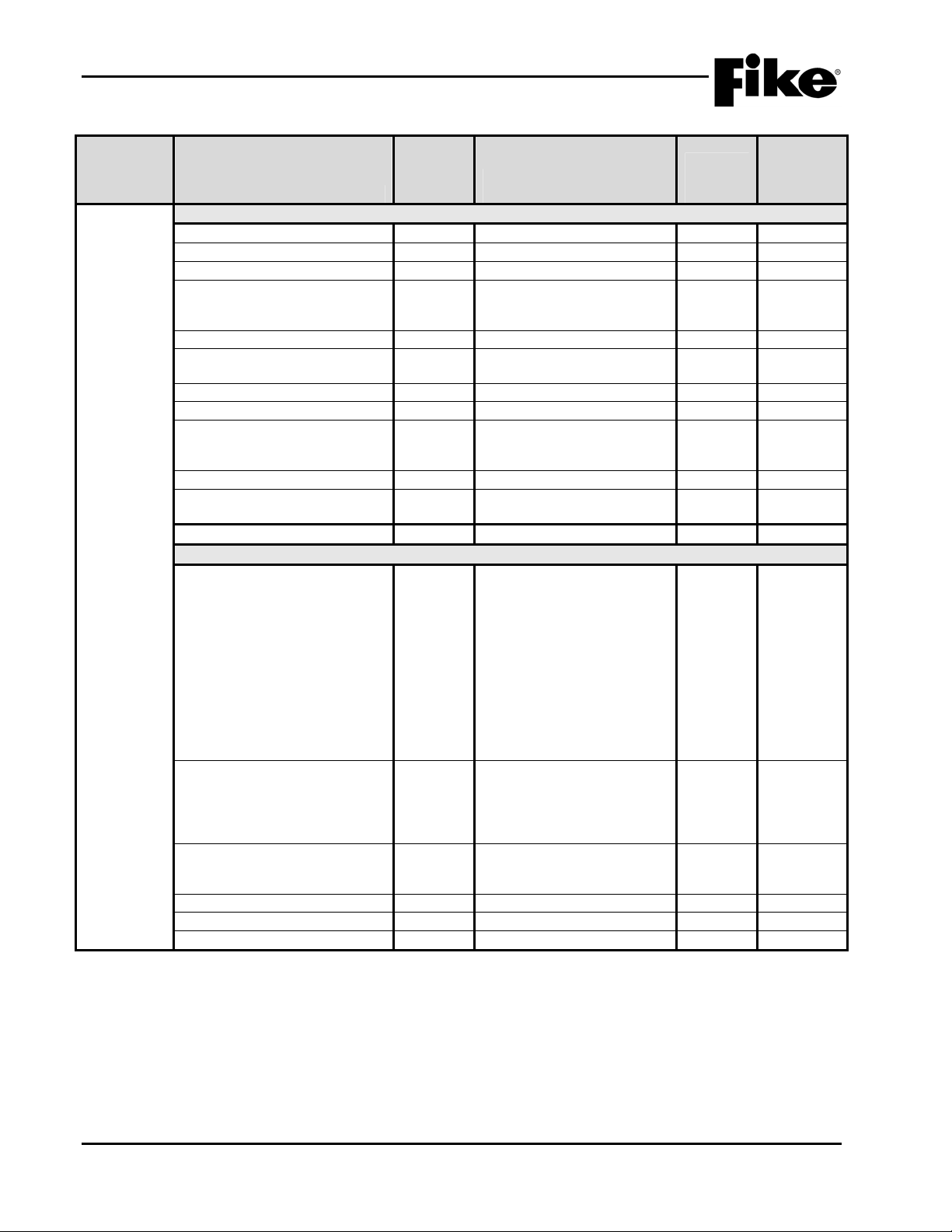
Exhibit 2-16: Programming Features Cont.
Permitted
in UL
Circuit or
Component Program Feature or Option
Defaults
(Relay
Module)
Common
Loop Number of Device Y
Address of Device Y
Output Y
Custom Message Y 60 character user defined
Zone Assignments (Device
Troubles)
AHU Shutdown Relay Y
Restart Delay Y
Misc. Options
(feedback relay monitoring)
Positive Alarm Sequencing
(PAS)
Output Control (Note 6)
Activation State Y
Action Type Y
Relay State Y
Timeout Y
State Counter Y
Output Y
Drill Y
Zone Assignments (activation) Y
Notes:
1. Cheetah Xi can have up to four (4) addressable loops.
2. Timeout delay becomes active if relay state is set to ‘Time Delay’.
3. Can be assigned to any 3 zones, 254 any zone, or 255 any zone (non-disable).
4. Restart delay becomes active if relay is configured for AHU shutdown operation.
5. These options are not available if relay is configured for AHU shutdown operation.
6. Output control is disabled if relay is set for AHU Shutdown operation.
864?
(Y/N)
Y
Y
Y
Y
Possible Settings
(Defaults shown bold)
1 - 4
1 – 254
Enabled/Disabled
(1-001 RELAY MODULE
Loop 1 - Address 001)
Default/User Defined
1 – 253
(4 zones available)
Enabled / Disabled
0 – 255 seconds
Not Monitored / Monitored
by dry contact / Independent
dry contact
Enabled / Disabled
Alarm / Summing Alarm /
Test Alarm / Alarm
Verification ON / Pre-Alarm 1
/ Pre-Alarm 2 / Supervisory /
Trouble / Open Circuit
Trouble / Short Circuit
Trouble / Low Power Trouble
/ Maintenance Trouble /
Process / Zone Disable
Switch / Release / PreDischarge / Abort / Release
Circuit Trouble
No Action / Activate on Any
of 3 zones / Activate on All of
3 zones / Activate on Specific
Device / Activate on multiple
priority rows active
ON / OFF / Timed / Time
Delay
0 – 80 minutes
1 – 16
Silenceable/Non-Silenceable
Enabled / Disabled
0 - 255
Settings
permitted
in UL 864 Notes
1
4
5
5
2
3
Cheetah Xi Programming Manual 2-17
P/N: 06-651 Rev 1, 09/2013
2.0 C-Linx PROGRAMMING OPTIONS
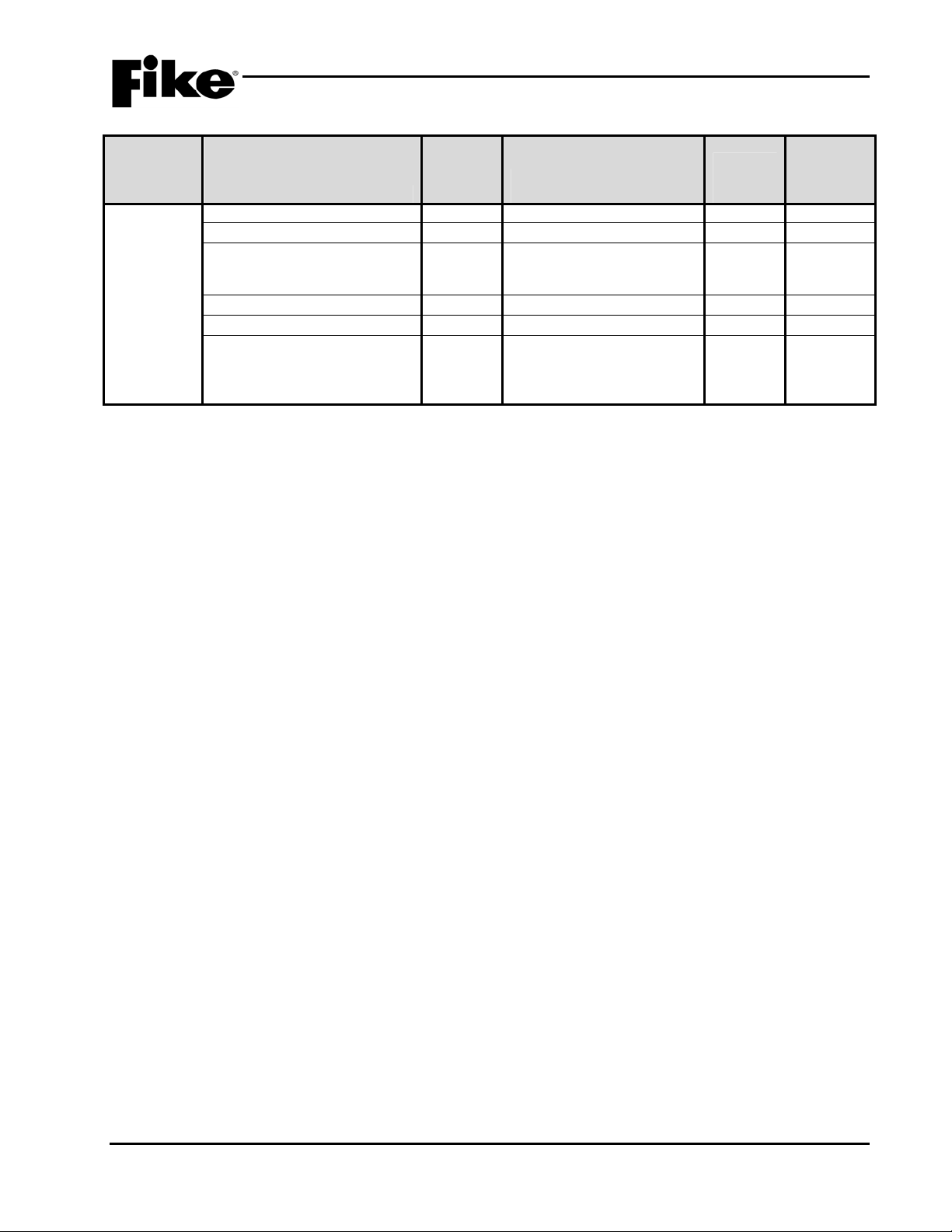
Exhibit 2-17: Programming Features Cont.
Circuit or
Component Program Feature or Option
Defaults
(Releasing
Module)
Common
Loop Number of Device Y
Address of Device Y
Output Y
Custom Message Y 60 character user defined
Zone Assignments Y
Output Type Y
Output State Y
Notes:
1. Cheetah Xi can have up to four (4) addressable loops.
Permitted
in UL
864?
(Y/N)
Y
Possible Settings
(Defaults shown bold)
1 - 4
1 – 254
Enabled/Disabled
(1-001 RELEASING MOD
Loop 1 - Address 001)
Default/User Defined
1 – 253
(3 zones available)
No Output / Solenoid /
Expanded Solenoid /
Masterbox / ARM/IRM /
Expanded ARM/IRM /
Watermist System
No Output State / Alarm / PreDischarge / Release
Settings
permitted
in UL 864 Notes
1
2-18 Cheetah Xi Programming Manual
Rev 1, 09/2013 P/N: 06-651
2.0 C-Linx PROGRAMMING OPTIONS
Exhibit 2-18: Programming Features Cont.
Permitted
in UL
Circuit or
Component Program Feature or Option
Defaults
(FAAST
Detector)
Notes:
1. Cheetah Xi can have up to four (4) addressable loops.
2. Can be assigned to 4 discrete zones, 2 zone ranges or 1 range and 2 discrete zones.
3. Each detection level on the FAAST detector can be mapped to a panel state (user defined).
4. Each detection level can be configured as a latching or non-latching event. Must be latching if configured for alarm.
5. Each detection level can be configured to initiate one of three Alarm Verification timers.
6. Allows you to set the high sensitivity level for the selected acclimate range.
Common
Loop Number of Device Y 1 - 4 1
Address of Device Y 1 – 254
Custom Message Y 60 character user defined
Zone Assignments Y
Predischarge Type Y
Walktest
States
State Assignments
Fire 2 / Fire 1 / Action 2 / Action 1
/ Alert
Alarm Verification Timers
Fire 2 / Fire 1 / Action 2 / Action 1
/ Alert
Verification Timer Values
Timer 1 / Timer 2 / Timer 3 Y
Acclimate
Acclimate Y
Acclimate High Range Y Range 1-H
864?
(Y/N)
Y
Y Enabled / Disabled
Y 0.1% - 0.99645% ft. (slider)
Y
Y
Y
Possible Settings
(Defaults shown bold)
(1-001 FAAST DETECT
Loop 1 - Address 001)
Default/User Defined
1 – 253
Alarm Only Device / 1
Zone Device / 2
Device / Count Zone Device /
Single Release Device
Disabled / Alarm / PreAlarm 2 /
PreAlarm 1 / Supervisory /
Process
Latching / Non-Latching
No Timer / Timer 1 / Timer 2 /
Timer 3
0 – 255 (seconds)
st
nd
Cross
Cross Zone
Enabled / Disabled
(0.00046%ft – 0.04980%ft)
Range 2-M
(0.05%ft – 0.09982%ft)
Range 3-M
(0.1%ft – 0.99645%ft)
Range 4-L
(1%ft – 3.98818%ft)
Settings
permitted
in UL 864 Notes
2
3
4
5
6
Cheetah Xi Programming Manual 2-19
P/N: 06-651 Rev 1, 09/2013
2.0 C-Linx PROGRAMMING OPTIONS
Exhibit 2-19: Programming Features Cont.
Circuit or
Component Program Feature or Option
Defaults
(FAAST
Detector)
Notes:
1. Set to 255 to disable Analog Broadcast.
2. Reference detector cannot use Acclimate feature.
Day Sensitivity Levels
Fire 1 Y
Copy Nighttime Sensitivity Y
Night Sensitivity
Fire 1 Y Range 1-H
Copy Nighttime Sensitivity Y
Miscellaneous
Particulate Level Display Y
Air Flow Trouble Boundary Y 0 – 100 (% off normal)
Air Flow Trouble Timer Y
Security
Test Button Locked Y
Isolate Button Locked Y
Passcode Y
Device Disable (Isolate Button) Y
Reference Detector
Analog Broadcast Increasing
Step
Analog Broadcast Decreasing
Step
Reference Detector Y
Relays
Configuration (Relays 1 – 5) Y
Configuration (Relay 6) Y
Permitted
in UL
864?
(Y/N)
Y
Y
Y
Y
Possible Settings
(Defaults shown bold)
Range 1-H
(0.00046%ft – 0.04980%ft)
Range 2-M
(0.05%ft – 0.09982%ft)
Range 3-M
(0.1%ft – 0.99645%ft)
Range 4-L
(1%ft – 3.98818%ft)
Yes / No
(0.00046%ft – 0.04980%ft)
Range 2-M
(0.05%ft – 0.09982%ft)
Range 3-M
(0.1%ft – 0.99645%ft)
Range 4-L
(1%ft – 3.98818%ft)
Yes / No
Fire 2 / Fire 1 / Action 2 /
Action 1 / Alert
(20 default)
0 – 255 (100 default)
Enabled/Disabled
Enabled/Disabled
0 – 9999 (1111 default)
Enabled / Disabled
0 - 255
0 - 255
0 - 254
Latching: Yes / No
Fire 2 / Fire 1 / Action 2 /
Action 1 / Alert
Latching: Yes / No
High Airflow / Low Airflow /
Isolate / Filter Minor / Filter
Urgent / Filter Door / Config /
Aspirator / Low Voltage /
Comm / Time / Sensor
Settings
permitted
in UL 864 Notes
1
1
2
2-20 Cheetah Xi Programming Manual
Rev 1, 09/2013 P/N: 06-651
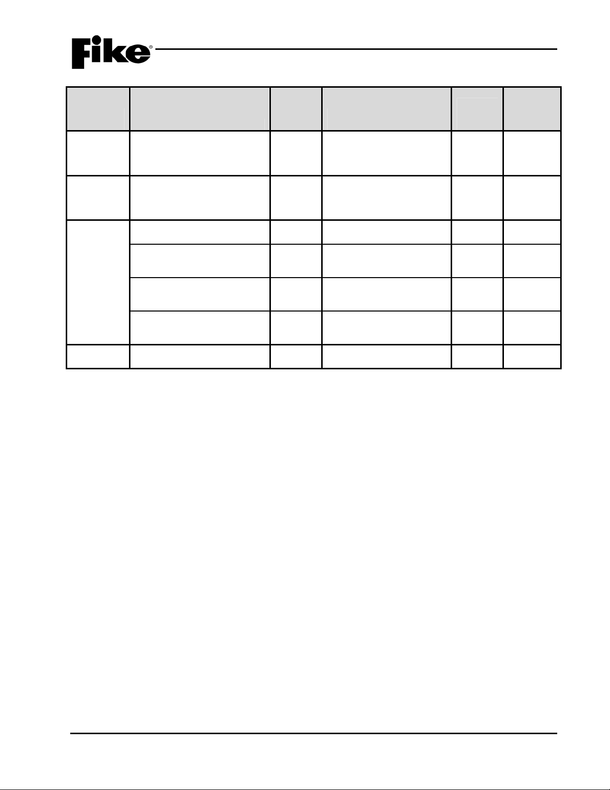
2.0 C-Linx PROGRAMMING OPTIONS
Exhibit 2-20: Programming Features Cont.
Circuit or
Component Program Feature or Option
Defaults
(Update
Device
Checksum)
Defaults
(Reset
Default
Config)
Defaults
(Custom
Messages)
Defaults
(Password)
Recalculate addressable device
Configuration Checksums?
Reset All Default Device
Configurations?
Panel LCD Custom Message
Line 2 Logo
Addressable Devices
(Restores all device custom
messages to default)
Peripheral Devices
(Restores all device custom
messages to default)
Air Sampling Devices
(Restores all device custom
messages to default)
Used to assign a unique Level 2
password (8 available)
Permitted
in UL
864?
(Y/N)
Y Yes / No
Y Yes / No
Y 20 character user defined
Y Yes / No
Y Yes / No
Y Yes / No
Y 4 digit user defined
Possible Settings
(Defaults shown bold)
(Fike Corporation)
Settings
permitted
in UL 864 Notes
Cheetah Xi Programming Manual 2-21
P/N: 06-651 Rev 1, 09/2013
2.0 C-Linx PROGRAMMING OPTIONS
Exhibit 2-21: Programming Features Cont.
Permitted
in UL
Circuit or
Component Program Feature or Option
Peripheral Device Configuration Options
Remote
Display 14
Address Y
Custom Message Y 20 character user defined
Key
Corporate Logo Y 20 character user defined
Buzzer Operation Y
Network History Display Y
Countdown Display Y
Countdown Filter Y
Programmable Key Functions
(1 – 8)
Remote
Display 2
and 10 Key
Address Y
Custom Message Y 20 character user defined
Corporate Logo Y 20 character user defined
Buzzer Operation Y
Network History Display Y
Countdown Display Y
Countdown Filter Y
Notes:
1. Process and Zone Disable will require a zone number be assigned (1 – 253).
864?
(Y/N)
2 - 32
(Fike Remote Display)
(Fike Corporation)
Buzzer Enabled / Buzzer
Disabled
Show All History / Filter
History by Zone
Show Countdown Display /
Show Release Imminent
Show All Zone Countdowns
/ Filter Countdown by Zone /
Do not show Countdown
Y NO Function / Reset / Silence
/ Acknowledge / Drill /
Process / Walktest / IR Tool /
Step Alarm / Step
Supervisory / Step Trouble /
Step All / Fan Restart / Zone
Disable
2 - 32
(Fike Remote Display)
(Fike Corporation)
Buzzer Enabled / Buzzer
Disabled
Show All History / Filter
History by Zone
Show Countdown Display /
Show Release Imminent
Show All Zone Countdowns
/ Filter Countdown by Zone /
Do not show Countdown
Possible Settings
(Defaults shown bold)
Settings
permitted
in UL 864 Notes
1
2-22 Cheetah Xi Programming Manual
Rev 1, 09/2013 P/N: 06-651
 Loading...