

Cheerson CX-20 User Manual
Auto-Pathfinder
6 - Axis System
USER MANUAL
SWB
1
0
0
1
2
SWA
0
+
0
+
0
+
0
+
0
+
0
+
0
+
0
+
1 of 7 2 of 7 3 of 7 4 of 7
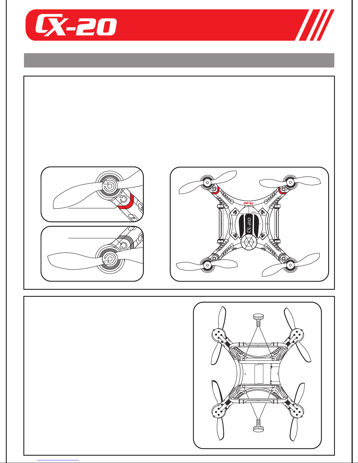
1 Installation instructions
1 The Propellers Installation
(1)To prepare the quadcopter and propellers
(2)The propeller with spin-mark should be installed upward, and to make sure
the spin-mark of propellers and its equipped motor rotate in the same
direction.
(3)To use the hexagon wrench in the kits to tighten the omament cap of the
motor ( Note:For the black omament cap, to tighten the cap anticlockwise,
for the silver cap, to tighten it clockwise ).
Anti-clockwise
propeller
Anti-clockwise signal
Clockwise signal
Clockwise propeller
2 The Landing Gear &
Antenna Installation
(1)To prepare the quadcopter and
landing gears.
(2)To install the landing gear with the
antenna hole on the body with antenna,
and to fix the landing gear with the screws.
(3)Install the other landing gear on
other side, and to fix the landing gear
with screws.
(4)To place and fix the antenna in
the groove of the landing gear
with 3M scotch tape.
SWB
1
0
0
1
2
SWA
0
+
0
+
0
+
0
+
0
+
0
+
0
+
0
+
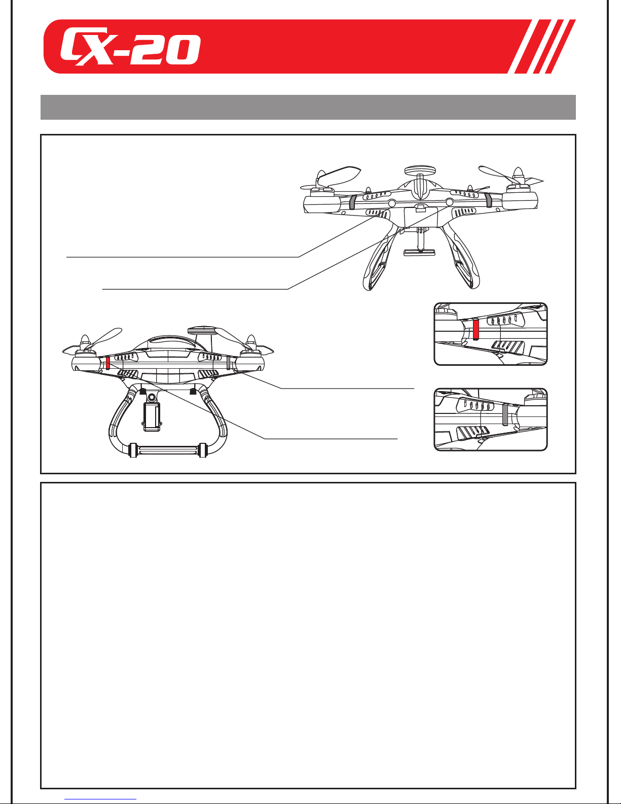
2 The instructions for the indicator lights and the status
1 LED instruction
The indicator light for the main control
board calibration, motor unlock/lock
instructional light (YELLOW light/RED light)
GPS signal instructional light
(GREEN light)
The rear downward LED
(GREEN)
The front downward LED (RED)
The front downward LED
(RED)
The rear downward LED (GREEN)
2 The descriptions of the LED indicator light status
(1)The front indicator light: a. The red light keeps steady when the motor
starts. b. The red light blinks in low voltage and there is a alarm sound
if the frequency is below 1Hz.
(2)The rear indicator light: a. the green light keeps steady when the motor
starts. b. The green light blinks and there is a alarm sound if the
frequency is below 1Hz.
(3)The indicator light of the main control board calibration, motor
lock/unlock indicator light. The yellow indicator light and red indicator
light blink alternately when the main control board calibrates. The red
light blinks slowly when the motor is locked, and the red indicator light
keeps steady when motor is unlocked.
(4)GPS signal indicator LED light: The green indicator light blinks when
less than 6 satellites from the GPS system are received; the green
indicator light keeps steady when more than 6 satellites from the GPS
system are received. NOTE: The satellites received from the GPS
system must be more than 6 satellites in Stable Mode and
Return Home Modes. (The green indicator light keeps steady)
 Loading...