

Page 1

Model G-50 Cable/Continuity Tester
INSTRUCTION MANUAL
CheckSum LLC
P.O. Box 3279
6120 195th Street NE
Arlington, WA 98223
(360) 435-5510
Web Site: www.checksum.com
Page 2

P/N 4400-001
Revision 1/92
Copyright © 1988-1992 - CheckSum LLC - all rights reserved
Litho in U.S.A.
Specifications and operational characteristics of the System are subject to change. CheckSum LLC cannot take responsibility for any direct or consequential damages arising from
use of this manual or the related products.
IBM-PC, IBM-XT and IBM-AT are trademarks of International Business Machines, Inc.
MS-DOS is a trademark of Microsoft, Inc.
Page 3

Limited Warranty
Introduction
System Overview 5
Specifications
Installation Instructions
Overview 11
Model SR-500 I/O Module Installation 11
CheckSoft Software Installation 17
Fixture Installation 21
Table of Contents
9
Operating Instructions
Overview 23
Testing a Cable 26
Learning a Cable 32
Locating a Pin 41
Assembling a Cable 42
System Self-Test 43
Configure/Install System 45
Appendix A - Wiring Diagrams
Appendix B - Sample Reports
Appendix C - In Case of Problems
Appendix D - Error Messages
CheckSum Model G-50 Manual - Page 1
Page 4

Figures & Illustrations
Figure 1 - System Block Diagram 7
Figure 2 - SR-500 Jumpering 12
Figure 3 - SR-500 Installation 15
Figure 4 - System Menu 19
Figure 5 - Configure/Install System Menu 20
Figure 6 - SR-500 Test Point Pin Out 21
Figure 7 - System Menu 24
Figure 8 - File Select Menu 26
Figure 9 - File Selection List 27
Figure 10 - Test Failure Display 28
Figure 11 - Test Completed Menu 29
Figure 12 - Assembly Learn Menu 33
Figure 13 - Pin and Wire Name Entry Screen 34
Figure 14 - Operator Comments Entry Screen 36
Figure 15 - Sample Text File 39
Figure 16 - Pin Locating Display 41
Figure 17 - Cable Assembly Display 42
Figure 18 - Self-Test Result Display 43
Figure 19 - Self-Test Failure Display 44
Figure 20 - Configure/Install System Menu 45
Figure 21 - Report Configuration Menu 48
Figure A1 - SR-500 I/O Port Pin Out Ap 2
Figure A2 - Cable Test Report With Failure Ap 3
Figure A3 - Cable Test Report With No Failure Ap 4
Figure A4 - Cable Wiring Report Ap 5
Figure A5 - Batch Test Report Ap 6
Table A1 - SR-500 Base Address Jumpers Ap 8
Table A2 - Computer I/O Port Assignments Ap 9
Table A3 - File Error Messages Ap 11
CheckSum Model G-50 Manual - Page 2
Page 5

Limited Warranty
CheckSum LLC products, exclusive of fixturing products, are covered by a one-year
limited parts and labor warranty for defects in materials and workmanship from time of
original product shipment. Fixturing products (Model TR-3 series and Model GS-850) include a 90-day limited warranty. This warranty extends only to the original purchaser and
excludes products or parts that have been subject to misuse, neglect, accident, or abnormal conditions of operations.
CheckSum LLC reserves the right to replace the product in lieu of repair. If the failure
has been caused, as determined by CheckSum, to be due to misuse, neglect, accident, or
abnormal conditions of operation, repairs will be invoiced at a nominal cost. In such case,
an estimate will be submitted before the work is started, if requested.
THE FOREGOING WARRANTY IS IN LIEU OF ALL OTHER WARRANTIES, EXPRESS OR IMPLIED, INCLUDING BUT NOT LIMITED TO ANY IMPLIED WARRANTY OF MERCHANTABILITY, FITNESS, OR ADEQUACY FOR ANY PARTICULAR PURPOSE OR USE. CHECKSUM LLC SHALL NOT BE LIABLE FOR
ANY SPECIAL, INCIDENTAL, OR CONSEQUENTIAL DAMAGES, WHETHER IN
CONTRACT, TORT, OR OTHERWISE.
In the event of a failure of a product during the warranty period:
1.Contact CheckSum for a returned material authorization number (RMA).
2.Pack the product in its original packing material or suitable equivalent and return it
postage-paid to CheckSum LLC. Mark the package clearly with the RMA number.
3.CheckSum will repair the product and return it postage-paid. Repairs are typically completed within two working days of receipt.
CheckSum Model G-50 Manual - Page 3
Page 6

CheckSum Model G-50 Manual - Page 4
Page 7

Introduction
System Overview
The CheckSum Model G-50 Cable/Continuity Test System allows an IBM PC (or compatible) to efficiently test assemblies (such as cables and harnesses) containing up to 96
test points for shorts and opens. The System performs a continuity test from each point
to every other point in the assembly.
The CheckSum Model G-50 includes:
• One Model SR-500 I/O Module that is installed into the IBM PC. All of the System
electronics are included in the SR-500
• Two 50-Pin Ribbon Cables for connecting the SR-500 I/O Module to the cable or
harness
• A diskette containing CheckSoft Software that executes on your IBM PC with
MSDOS
• This Instruction Manual
The System can be expanded up to 768 test points with the addition of optional Model SR500 I/O Modules, each containing 96 test points.
The Model SR-500s can be connected directly to the test unit, or can be connected to
either a user-supplied or CheckSum-supplied fixture unit to facilitate ease in connecting
various test units to the System.
The optional CheckSum Model GS-850 Fixture can be used to provide an efficient means
of connecting a wide variety of cables to the Test System. It connects to one or two SR500s. Mating connectors are then installed on adapter boards that quickly attach to the
fixture via a zero-insertion force (ZIF) connector.
Figure 1 shows a block diagram of the System architecture when used with a Model GS850 Fixture System.
CheckSum Model G-50 Manual - Page 5
Page 8

The CheckSoft Software package included with the System provides a menu-driven
operator interface to the System. It is easy to use yet provides a wide variety of features
such as the following:
• Testing a cable
• Self-learning a known good cable
• Learning a cable from a text file
• Saving cable data to hard-disk or diskette
• Pin or wire locating
• Cable assembly aids
• Test printouts
• Cable wiring printouts
• System self tests
• System configuration
The CheckSoft Software Package also allows for assigning operator instructions and long
pin and wire names that can be displayed to help repair faulty cables.
CheckSum Model G-50 Manual - Page 6
Page 9

Figure 1 - System Block Diagram
CheckSum Model G-50 Manual - Page 7
Page 10

CheckSum Model G-50 Manual - Page 8
Page 11

Specifications
Model G-50 Continuity Test System
Includes:
• SR-500 I/O Module and Cabling
• CheckSoft Software
• Operator/User Manual
Model SR-500 I/O Module
• 96 Test I/O Pins, each of which can be assigned to any cable point
• Test signal: 5 V level, 24 mA
• Test speed: Approximately .11 seconds for 96 pins on an 8 MHz, one wait-state
computer; approximately .45 seconds for 192 pins
• Open/short threshold: 3 KΩ typical
• Maximum network size: 50 connections
• PC control: Jumperable I/O port addressing. Uses 32-byte address on the PC I/O
bus. Default Base Address is 300 hex
• Internal computer power supply requirements: Approximately 5 Watts (1 A @ 5
VDC)
• Computer requirements: One full-length slot in an IBM PC/XT/AT, PS-2 Model 30,
or full compatible
• Two +5 VDC and two GND pins are provided in the pin out and may be jumper-
activated on the SR-500
• Mating connectors: Includes ribbon cables that are terminated by 50-pin (25 X 2)
female connectors on .10" centers. Each cable is approximately 40" long.
• Warranty: One-year limited parts and labor warranty
CheckSum Model G-50 Manual - Page 9
Page 12

CheckSoft Software
• Media: Floppy diskette
• MS and PC-DOS compatible
• Configured for operation on monochrome, CGA, EGA, VGA and
Hercules-compatible displays
• Memory requirements: 256 KBytes
Functions provided:
• Learn cable from known-good sample
• Learn cable from text file created independently
• Save learned file on disk
• Test learned cable
• Loop test cable (for intermittents)
• Self-test of each I/O pin and control circuitry
• Wire identification via probe
• Propagation delay compensation
• Assign special operator instructions
• Assign pin names
• Assign wire names
• Print test results
• Print wiring data
CheckSum Model G-50 Manual - Page 10
Page 13

Installation Instructions
Overview
There are several steps in the installation process. The first step is installation of the SR500 Module(s) into your PC. The next step is installation of the CheckSoft Software.
Finally, the fixturing is installed. You should read through this entire installation section
before beginning.
Note
This installation procedure requires that you remove the cover from your PC for internal
installation of the SR-500 Modules. If you are not experienced with such procedures, you
should obtain the help of a qualified person to do the installation.
SR-500 I/O Module Installation
The first step of the installation procedure involves installing the SR-500 I/O Modules in
the PC.
Step 1.
Remove the power cord from your PC and turn off the power to minimize safety hazards
and to ensure that no damage is done to circuitry in the PC or in the SR-500s.
CAUTION
Ensure that you have removed the power from your PC. The power cable should be
completely disconnected from its receptacle and the power switch should be turned
off.
Step 2.
Remove the cover from your PC. Typically, the cover is secured with five screws on the
back, one in each corner and one in the center top.
Step 3.
CheckSum Model G-50 Manual - Page 11
Page 14

Discharge static electricity. Use an antistatic wrist strap when doing the following to minimize potential electrostatic discharge (ESD) damage to your computer. If you do not
have one, at a minimum, place your hand on the chassis of the PC to discharge any
electrostatic potential your body may contain.
Step 4.
Ensure that your SR-500s are jumpered correctly. As Figure 2 shows, the default configuration uses jumpers on BASE ADDRESS positions ADR 7, 6, and 5. No other address
jumpers should be installed. The BASE ADDRESS for all SR-500s should be identical.
If you have only one SR-500, ensure the BOARD SELECT jumper is installed for BD
position 1 (the leftmost pair). If you have more than one SR-500, each should be
jumpered sequentially. There should never be more than one jumper installed on the
BOARD SELECT strip.
Note
The VCC jumpers on the BASE ADDRESS strip provide the capability to send + 5 V
VCC power from the PC to the SR-500 ribbon cables. Since this is unfused power it is
highly recommended that these jumpers are not installed to prevent damage to the PC,
SR-500, and/or external equipment.
Figure 2 - SR-500 Jumpering
CheckSum Model G-50 Manual - Page 12
Page 15

Step 5.
For each of the SR-500s, install as described below and as shown in Figure 3:
The following instructions assume that you are positioned in front of the computer, facing
the front panel.
If you are installing several cards, install them from right to left. Install the cards with the
addressing (BOARD SELECT jumpers) in sequential order, beginning on the right. They
will work in any order, but it is easier to keep track of the cabling if you use this convention.
Note
If there is a card installed in the slot to the left of the slot desired for the SR-500, temporarily remove it to provide additional room.
1.Remove the blank slot cover from the desired slot. Save the screw for reinstallation in
step 5.
2.Slide the card into the desired position, but not with the board-edge fingers engaged into
the motherboard connector.
Position the back end (with the bracket) of the SR-500 to the left to provide working
room.
3.Install the first of the two cables to JP 4 on the SR-500. Pin one (typically indicated by a
red tracer on the cable) should be toward the bottom. Install the end of the cable without
the white handle and strain relief to the SR-500. Fully seat the cable by pressing the
cable connector onto its corresponding header.
4.Install the other of the two cables to JP 3 on the SR-500. Pin one (typically indicated by a
red tracer on the cable) should be toward the bottom. Install the end of the cable without
the white handle and strain relief to the SR-500. Fully seat the cable.
5.Ensure that the cables are nested in their proper position on the SR-500’s
back panel bracket.
Reposition the SR-500 over the motherboard connector and fully seat it.
Install the screw removed in step 1 through the top of the back panel bracket into the PC
chassis to hold the SR-500 in place.
CheckSum Model G-50 Manual - Page 13
Page 16

Repeat steps 1 through 5 for each SR-500 that you are installing.
Step 6.
Reinstall the cover of the PC.
Step 7.
Reinstall power to the PC and boot it up.
CheckSum Model G-50 Manual - Page 14
Page 17

Figure 3 - SR-500 Installation
CheckSum Model G-50 Manual - Page 15
Page 18

CheckSum Model G-50 Manual - Page 16
Page 19

CheckSoft Software Installation
The next step of the installation procedure involves installing the CheckSoft Software in
your computer.
CheckSoft Software is provided on a floppy diskette that is also compatible with standard
PCs.
Depending on your hardware configuration, there are two installation procedures. The
first is used if you have a hard disk drive in your System. The second is used if you do not
have a hard disk drive. In this case, the System is run from the floppy disk drive.
Note
Throughout the manual and when using the software, keys to be pressed are represented
with their nam e surrounded by square brackets. For exam ple, the Escape key is represented by [ESC].
Hard Disk Drive Installation
If you have a hard disk drive in your System (drive C:), you will want to install the CheckSoft Software onto it. The installation procedure installs it in a new subdirectory called
CHECKSUM.
Step 1.
Start your computer and go to the root directory of C: by typing:
C:[Enter]
CD \[Enter]
Step 2.
Insert the CheckSoft Software diskette into your A: drive.
Step 3.
The installation procedure creates a directory on your hard drive (C:) called \CHECKSUM. A file called CABLE.BAT is copied onto the root directory to start the System
CheckSum Model G-50 Manual - Page 17
Page 20

easily. Ensure that this directory and file name do not conflict with any existing ones on
your disk.
To install the software as described, type:
A:INSTALL[Enter]
Follow the instructions shown on the computer display.
Step 4.
Remove the CheckSoft Software diskette and store it in a safe place.
Step 5.
Start the CheckSoft Software by typing:
CABLE[Enter]
In this configuration, the operating software is stored in the \ CHECKSUM directory.
Cable testing can be initiated by typing CABLE from either the root or \CHECKSUM
directories.
Floppy Disk Drive Installation
If you do not have a hard disk drive in your System, use this procedure.
Step 1.
The first step is to back up the CheckSoft Software diskette. Have a spare floppy diskette
ready. Insert the CheckSoft diskette into the disk drive. Type:
DISKCOPY A: B:[Enter]
Follow the instructions with the source disk being CheckSoft Software and the destination
disk being your blank diskette. If you need additional instructions for this operation, refer
to your DOS manual.
Once this operation is complete, store the original CheckSoft Software diskette in a safe
place for when you need it in the future.
Put your copy of the CheckSoft diskette into Drive A:.
Step 2.
You are now ready to start the CheckSoft Software. Type:
CABLE[Enter]
CheckSum Model G-50 Manual - Page 18
Page 21
To initiate cable testing in the future, insert your diskette in A: and type:
A:[Enter]
CABLE[Enter]
In this configuration, your operating programs and cable data are stored on A:. You may
insert a different disk in A: to save and retrieve cable data once CheckSoft Software is
running. Alternatively, you can save cable data on the same disk as the CheckSoft
Software. If you have a two-drive System, you can change the data path to be B: with the
System Setup / Configuration menu.
Completing the Software Installation
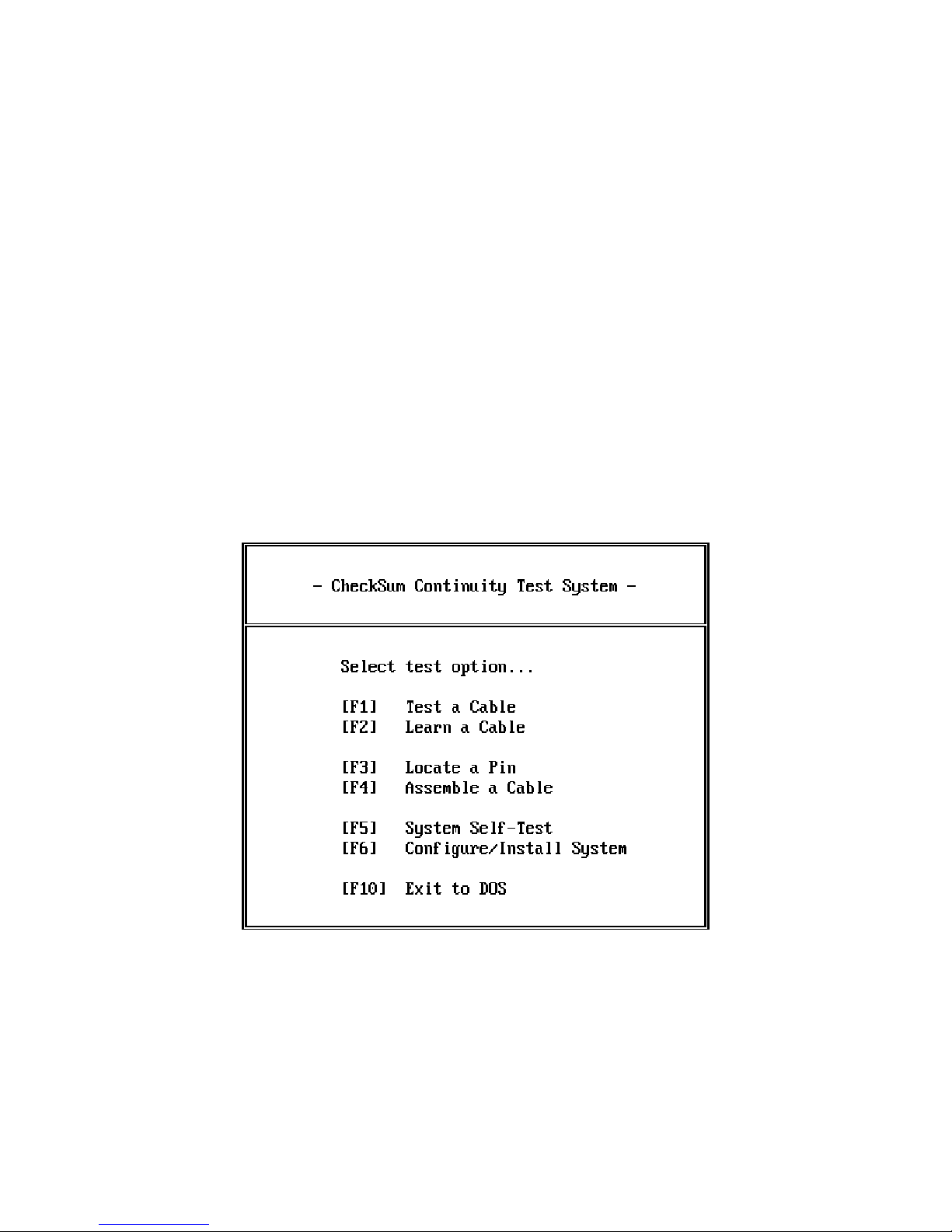
You will see the introductory directory, the System menu:
Select [F6] - Configure/Install System. You will then see the configuration menu shown in
Figure 5.
Figure 4 - System Menu
CheckSum Model G-50 Manual - Page 19
Page 22
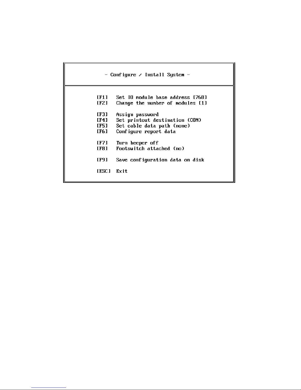
Figure 5 - Configure/Install System Menu
If you have installed a different number of SR-500 Modules than shown in the [F2] option, press [F2] until the proper number is shown.
If you changed any settings, press [F9] to save the changes to the disk. If you are running
from drive A:, ensure that the disk containing CheckSoft Software is installed.
Press [ESC] to return to the System menu shown in Figure 6.
Press [F5] from the System menu to execute the System self-test. The self-test verifies that
all of the I/O pins (called ports) on the SR-500s are operational.
If you need further instructions in the use of the self-test, refer to the System Self-Test
section of the manual.
If errors are reported, refer to Appendix C. Otherwise, continue on to Fixture Installation.
CheckSum Model G-50 Manual - Page 20
Page 23
Fixture Installation
Connecting to a Fixture
It is next necessary to connect the ribbon cables from the test electronics to mating connectors for the assemblies that you will be testing.
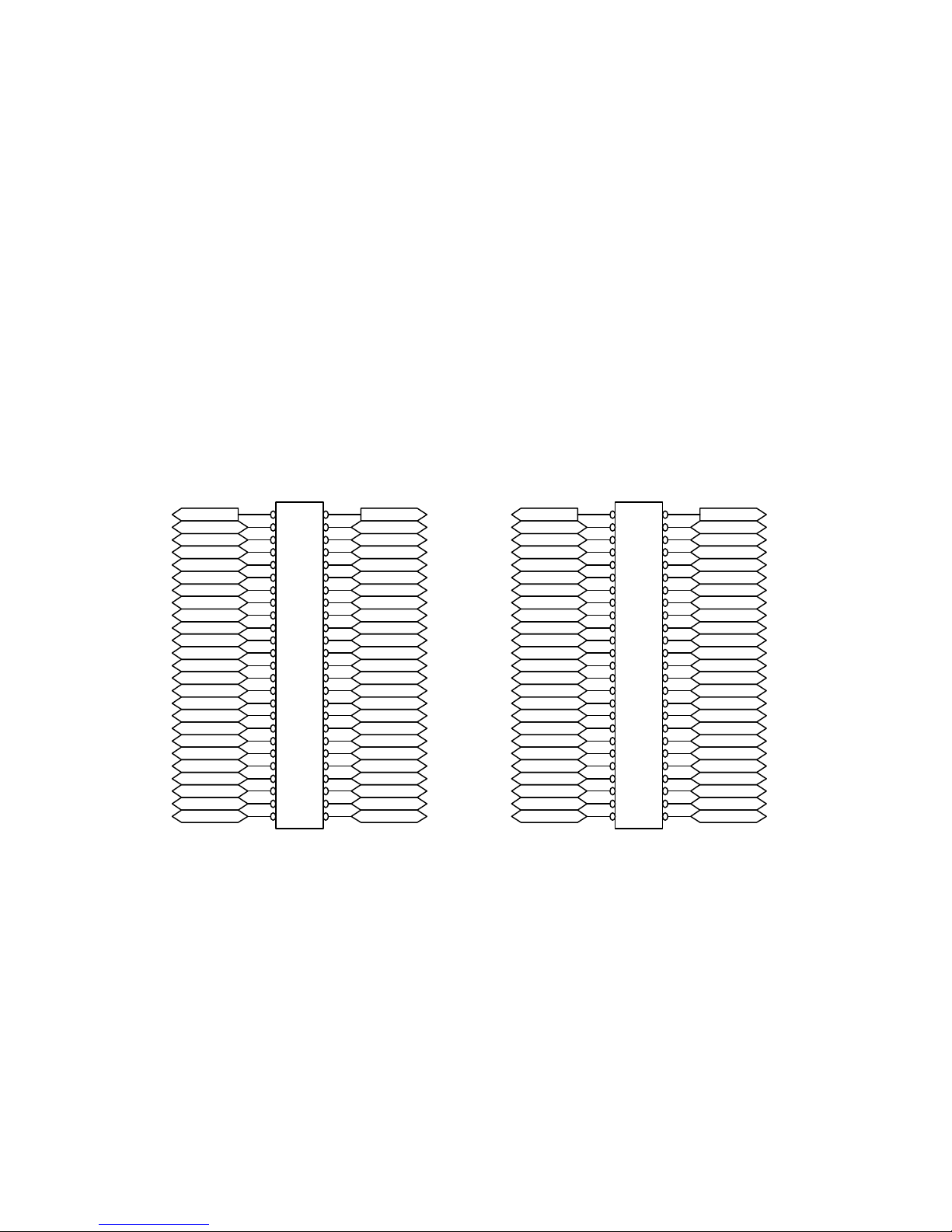
The pin-out of the connectors on the SR-500 modules is shown in Figure 6 below. The
UUTVCC1
Port 48
Port 46
Port 44
Port 42
Port 40
Port 38
Port 36
Port 34
Port 32
Port 30
Port 28
Port 26
Port 24
Port 22
Port 20
Port 18
Port 16
Port 14
Port 12
Port 10
Port 8
Port 6
Port 4
Port 2
JP3
4950
4748
4546
4344
4142
3940
3738
3536
3334
3132
2930
2728
2526
2324
2122
1920
1718
1516
1314
1112
910
78
56
34
12
Viewed as facing component side of PCB
UUTGnd1 UUTVCC2
Port 47
Port 45
Port 43
Port 41
Port 39
Port 37
Port 35
Port 33
Port 31
Port 29
Port 27
Port 25
Port 23
Port 21
Port 19
Port 17
Port 15
Port 13
Port 11
Port 9
Port 7
Port 5
Port 3
Port 1
Port 96
Port 94
Port 92
Port 90
Port 88
Port 86
Port 84
Port 82
Port 80
Port 78
Port 76
Port 74
Port 72
Port 70
Port 68
Port 66
Port 64
Port 62
Port 60
Port 58
Port 56
Port 54
Port 52
Port 50
Right Angle Header
JP4
4950
4748
4546
4344
4142
3940
3738
3536
3334
3132
2930
2728
2526
2324
2122
1920
1718
1516
1314
1112
910
78
56
34
12
UUTGnd2
Port 95
Port 93
Port 91
Port 89
Port 87
Port 85
Port 83
Port 81
Port 79
Port 77
Port 75
Port 73
Port 71
Port 69
Port 67
Port 65
Port 63
Port 61
Port 59
Port 57
Port 55
Port 53
Port 51
Port 49
connector on the left (when facing the component side of the SR-500) is JP3 and the connector on the right is JP4.
Note that the top two pins of each connector are dedicated to VCC and Ground. These
signals are available only if the jumpers on the PCB are installed.
Figure 6 - SR-500 Test Point Pin Out
CheckSum Model G-50 Manual - Page 21
Page 24

If you have more than one SR-500 in your System, just add 96 to the port numbers as you
go from SR-500 to SR-500 in ascending order by module BOARD SELECT jumper numbers.
If you have purchased a Model GS-850, refer to the Fixture Manual for specifics of installation.
Note
If you are confused about the connections, use the probing feature of the System to identify the appropriate port numbers.
Once you have completed fixturing, you are ready to start testing cables. Continue on to
the Operating Instructions portion of this manual to learn how. When you have become
familiar with operation of the System, refer to the section Learning an Assembly for allowing the System to learn the connections for the specific cables that you have interfaced.
CheckSum Model G-50 Manual - Page 22
Page 25

Operating Instructions
Overview
This section tells you how to use your PC for continuity testing. If you have not already installed the CheckSum hardware and software into your PC, refer to the installation section for instructions.
To start the CheckSum Cable/Continuity Test System, the first thing to do is to power up
your computer.
If you do not have a hard disk drive, insert your copy of the CheckSoft disk into the A:
drive. Type in the sequence:
A:[Enter]
CABLE[Enter]
If you have a hard disk drive in your computer and are presently in the CheckSum or root
directory (\CHECKSUM or \), simply type:
CABLE[Enter]
You will then see the System menu as shown in figure 7.
CheckSum Model G-50 Manual - Page 23
Page 26
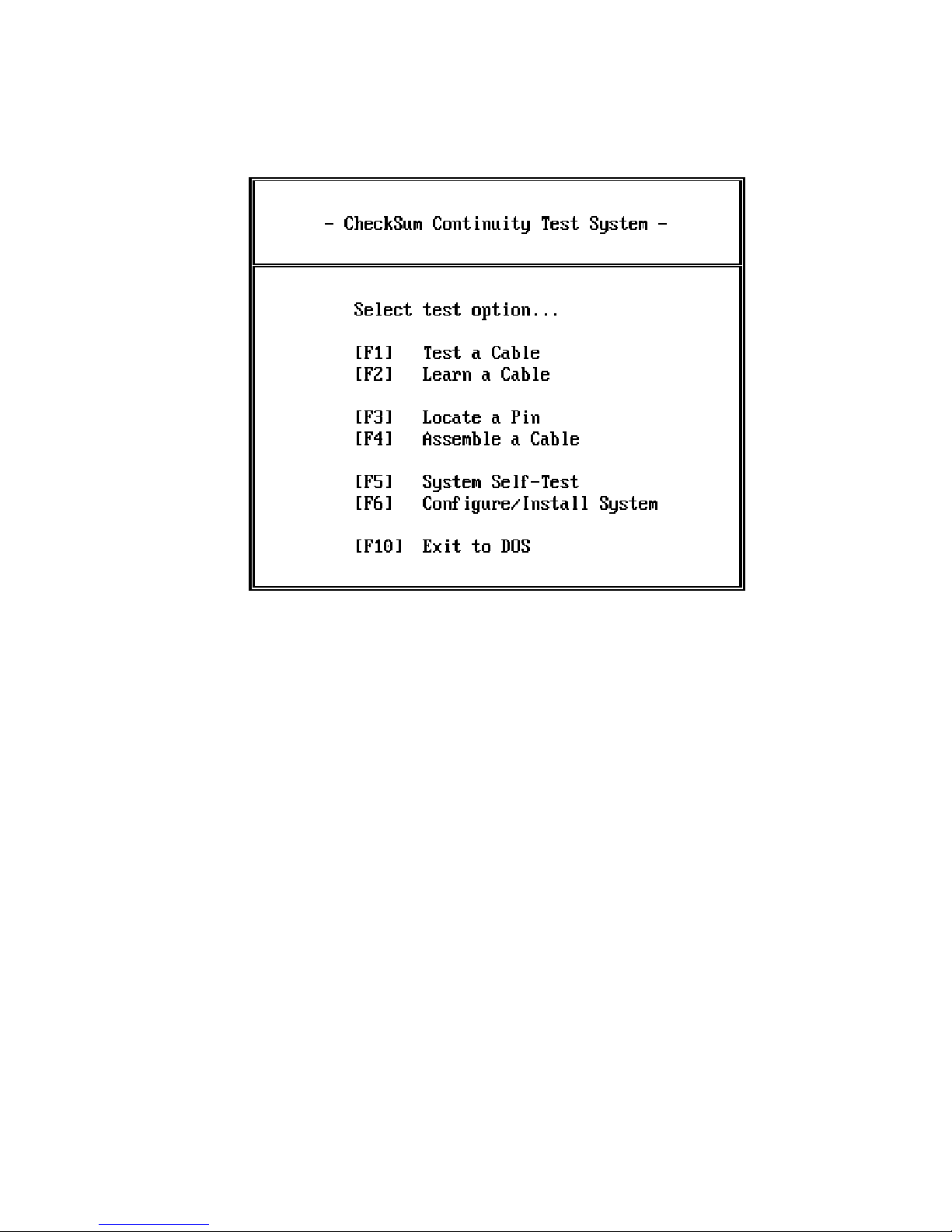
Figure 7 - System Menu
Each of the sections in this chapter describes one of the choices from this main menu. In
general terms, this is what each option will do for you:
[F1] is used if you wish to test a cable or harness. The cable must have been previously
"learned" by use of [F2]. The cable can be tested once or repetitively for intermittent
failures. The selection of [F1] also allows you to choose a data file describing the cable,
and to display or print test results.
[F2] is used if you want the System to learn the correct connections for a particular assembly. You can also use [F2] to assign alphanumeric pin and wire names, assign
operator instructions, assign a cable name, learn about a cable from a PC file created
separately, save information about a cable on the disk, or get a report about how a cable
is wired.
[F3] is used if you would like to identify a lead on a cable or harness. It allows you to
probe a point. It then tells you which point you have probed.
CheckSum Model G-50 Manual - Page 24
Page 27

[F4] is used to help you assemble or repair a cable. It allows you to probe a pin on the
cable. Once you have probed the pin, the System will tell you where it should be connected.
[F5] is used to verify that your Cable Test System is operating properly. It tests each of
the I/O ports to verify that they are working properly.
[F6] is used to change the configuration of your testing environment. You can specify
which disk and directory that cable data is to be stored in, turn the beeper on and off,
specify the destination of printed reports, and tell the PC how the hardware is configured.
In addition, this option can be used to configure the reports generated by the System.
[ESC] allows you to terminate CheckSoft Software execution. Once this option is
selected, you return to the DOS environment.
CheckSum Model G-50 Manual - Page 25
Page 28
Testing a Cable
Selecting the Proper Cable Data
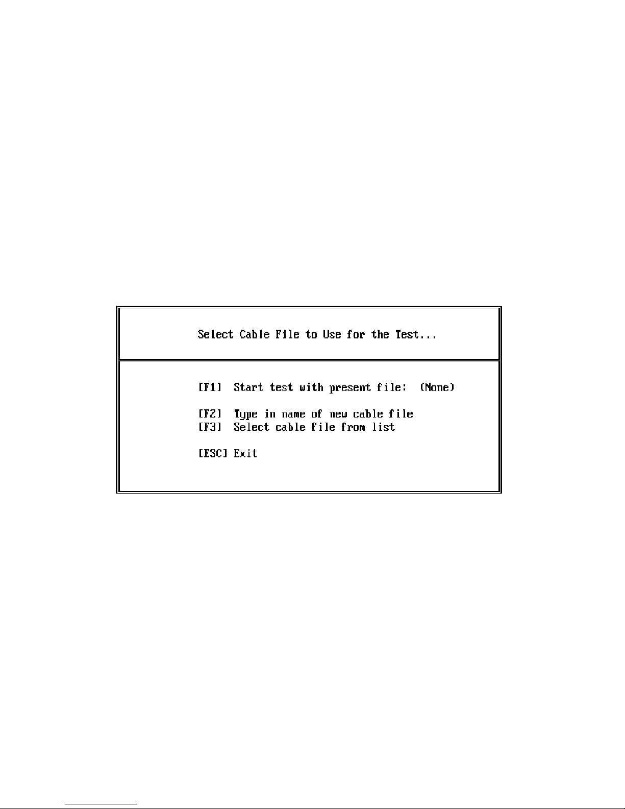
To perform a continuity test on an assembly, select [F1] from the System menu (Figure 6).
You then see the File Select menu shown in Figure 8.
In this menu, there are three choices.
When you initiate a cable test, it uses the cable information that is currently loaded in
memory. At the end of the [F1] line on the screen, you will see a name in parentheses.
This is the name of the file that is currently loaded into memory. If it is (None), no file
has been loaded into memory.
If a cable name has been assigned to the data in memory, it appears just before the file
name in parentheses.
If a cable has been learned, but not saved on disk, it is valid to continue with the test even
though no file name is present (i.e., "(None)" ). If a cable has not been learned, or data
Figure 8 - File Select Menu
CheckSum Model G-50 Manual - Page 26
Page 29
about a cable has not been loaded into memory, the System will expect not to find any
connections. Consequently, you may continue, but any connections that are present will be
reported as a cable error (unexpected short).
To load a cable into memory from the disk, use either options [F2] or [F3].
[F2] allows you to type in the file name of a cable data file to be loaded into memory.
Type in the name of the file (with up to eleven characters that do not include spaces or
special characters such as colons or periods). Errors that might occur are listed in Appendix D.
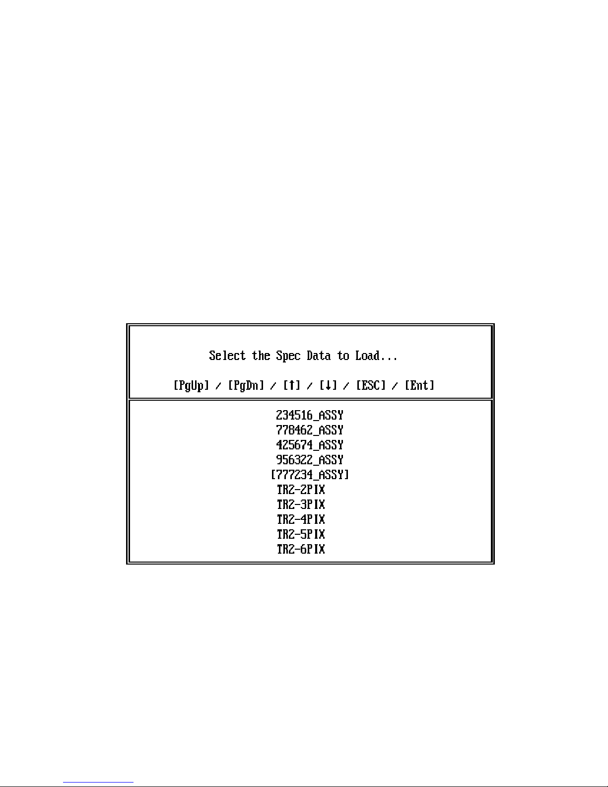
[F3] allows you to choose the data file from a list of those available on the disk that you
have chosen. This display is shown in Figure 9.
You may move up and down the displayed list with the up and down arrow keys or page
up and page down keys. When you press [Enter], the file name that has square brackets
around it is loaded into memory. If you do not wish to load a file into memory, press
[ESC] to exit.
Figure 9 - File Selection List
CheckSum Model G-50 Manual - Page 27
Page 30
Performing the Test
[F1] starts a test. If operator comments have been assigned, those are presented first.
When you are done reviewing the comments, press any key to continue.
Once you have initiated the test, the System briefly presents a message indicating that a
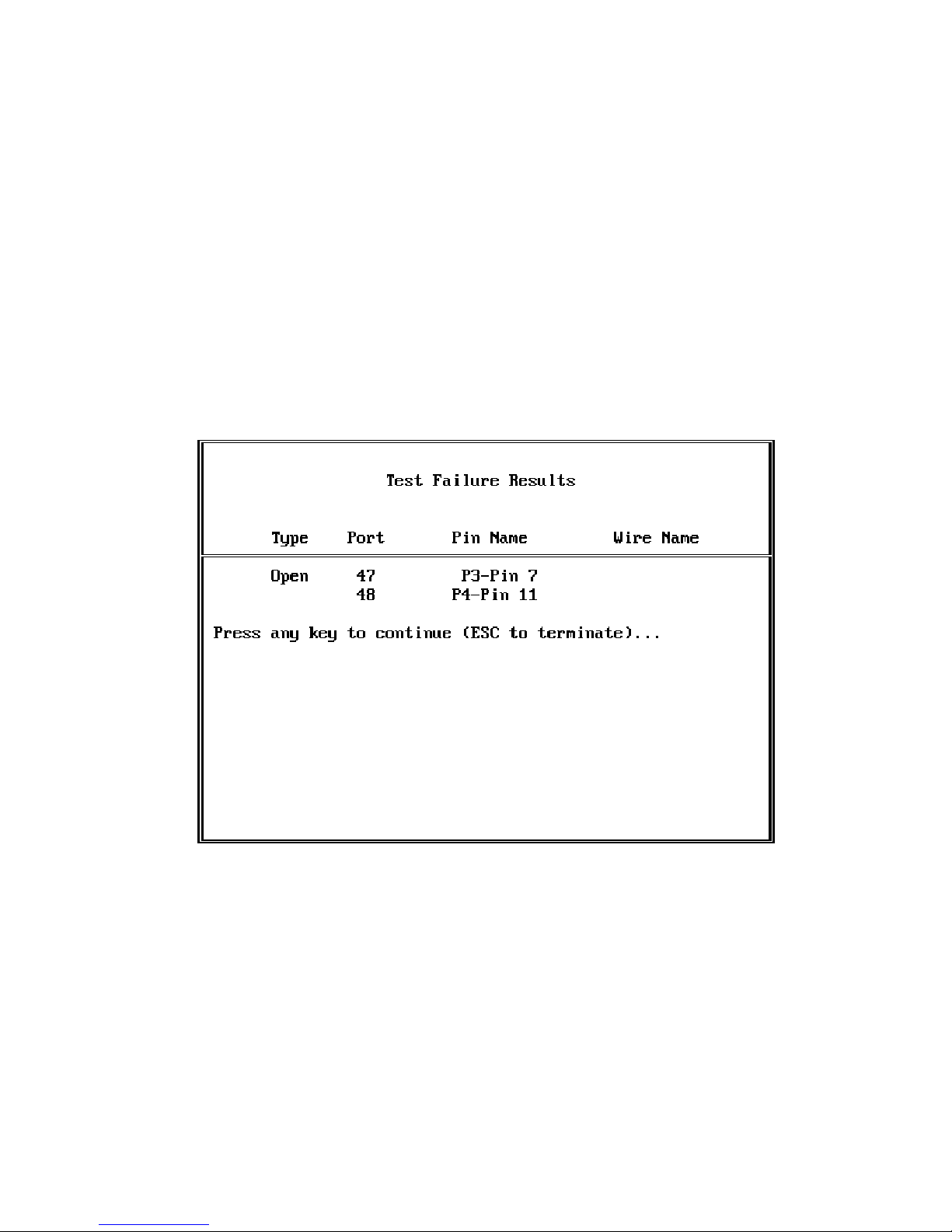
test is in progress. If a failure occurs, you will see the Test Failure display as shown in Figure 10.
The "Type" indicates whether an unexpected short or open type of error was encountered.
If it says "Short," that means that an erroneous short was encountered during the test.
Each error is reported once. For example, if a connection is expected from cable pin 4 to
cable pin 7, and the connection is not present, it is reported as an OPEN from pin 4 to
pin 7. It does not also appear as an open from pin 7 to pin 4.
Figure 10 - Test Failure Display
CheckSum Model G-50 Manual - Page 28
Page 31
The "Port" indicates the I/O pin number of the SR-500 Module installed in the PC. The
first SR-500 (the one closest to the left of the PC when looking from the back) contains
ports 1-96, the second SR-500 contains ports 97-192, and so on.
When looking from the back of the PC, the left cable from each SR-500 contains Ports 148 on its pin numbers 1-48. The right cable from each SR-500 contains Ports 49-96 on its
pins 1-48 respectively. On each cable, the top pins (49 and 50) are either open, ground,
or +5 V, depending on the SR-500 jumpering.
The Pin and Wire Names are optionally assigned when the cable is learned. Consequently
they may be blank or contain up to a 16-character description.
Pressing ESC from the Test Failure display returns you to the Test Completed menu.
Pressing anything else continues the test.
Concluding the Test
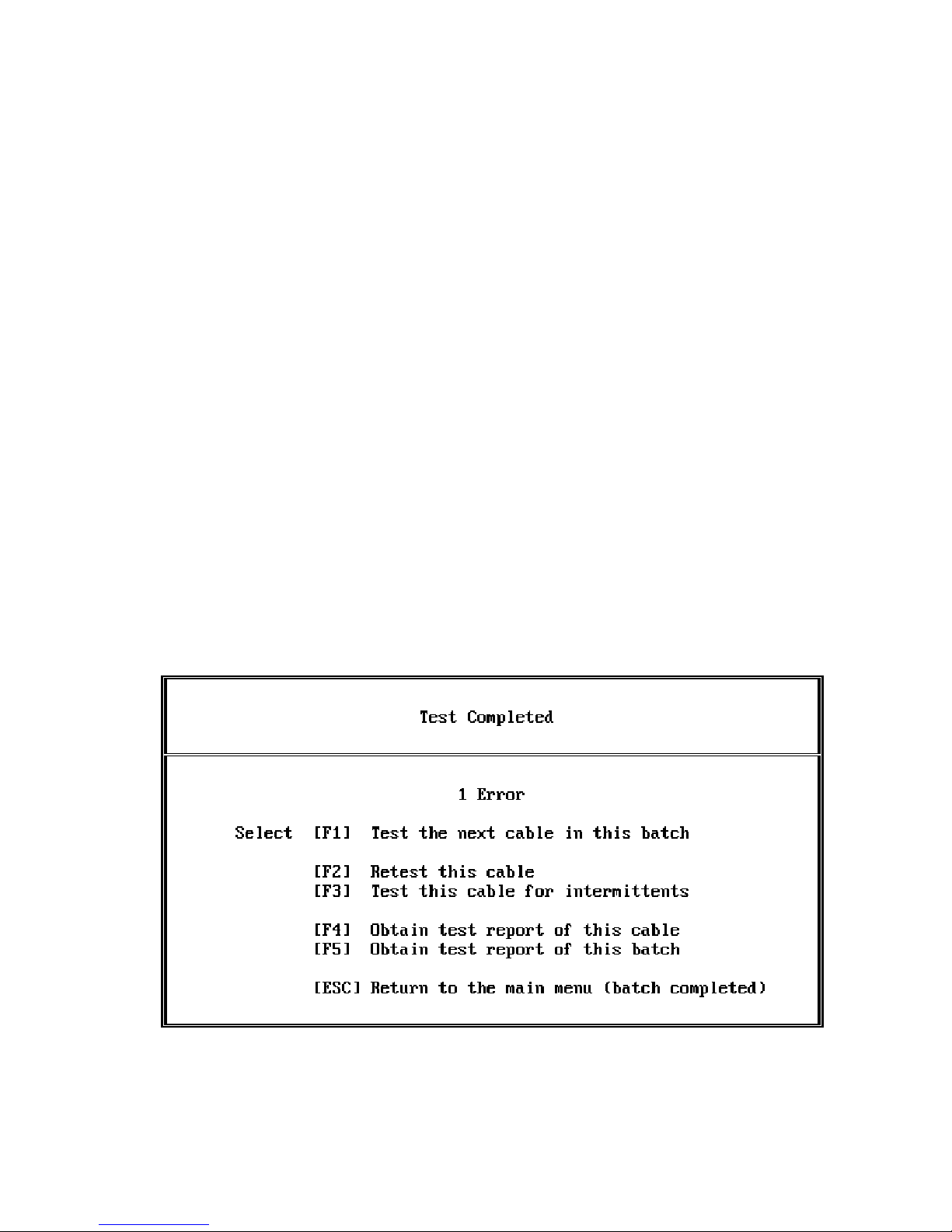
Once the test is completed (either with or without errors), you are presented with the Test
Completed menu shown in Figure 11.
Figure 11 - Test Completed Menu
CheckSum Model G-50 Manual - Page 29
Page 32

In this display, the total number of errors encountered in the test is shown.
[F1] is used to test the next cable in this batch. Operator comments are not redisplayed
in with this selection. The counter for the total number of cables in the batch is incremented when [F1] is selected.
[F2] allows you to retest the present cable without incrementing the total number of
cables in the batch.
[F3] is used to test the present cables for intermittent failures. In this mode, the System
repetitively executes a test for the cable. While this is occurring, you may flex or move
the cable to induce faults. The total number of passes is displayed. Any key can be
pressed to exit repetitive testing and return to the Test Completed menu. If errors occur
during repetitive testing, they are displayed and the System pauses for you to observe the
failure.
[F4] allows you to get a test report for this cable. The report goes to the destination
selected in the Setup/Configuration menu. If CON is selected, the report is displayed on
your CRT. Other choices include your PC’s printer or a disk file. The format of the
report is shown in Appendix B.
The test report includes the name of your facility (optionally assigned in the Report Con -
figuration menu), the Cable ID (the optional cable name assigned when the cable is
learned) and the date and time. It also contains the number of failures and an identity of
the cable tester. Even though a failure may have occurred more than once, it is counted
as a single failure only. This prevents excessively long reports after intermittent testing.
Each failure is listed in the report. The same information is presented as in the Test
Failure display, but in the report it is formatted slightly differently in order to be more
compact. In the center of each line, you will see a <=> if the failure was an unexpected short (connection) or an < > if the failure was an unexpected open.
[F5] allows you to get a test report for this batch. The report goes to the destination
selected in the Setup/Configuration menu. If CON is selected, the report is displayed on
your CRT. Other choices include your PC’s printer or a disk file. The format of the
report is shown in Appendix B.
The batch report includes the name of your facility (optionally assigned in the Report Con -
figuration menu) and the Cable ID (the optional cable name assigned when the cable is
learned). Depending on the configuration of your System (determined by the Report Con-
figuration menu), the System may solicit the Batch ID after you have requested a batch
CheckSum Model G-50 Manual - Page 30
Page 33

report. Your entry is printed in the report to describe which batch of cables (for example,
your internal purchase order number) is being reported on.
The report then includes a count of how many cables were tested in this batch, how many
cables had one or more failures, and the yield as a percentage of the batch that passed the
tests.
Finally, the report contains the date and time and the tester identification. Optionally, the
report can contain a list of the wiring for the cables tested. Whether the wiring list is included or not, as well as its format, is determined by the Report Configuration menu.
[ESC] Escape allows you to return to the main System menu to select a new cable or
begin a new batch.
CheckSum Model G-50 Manual - Page 31
Page 34

Learning a Cable
Overview
Learning a cable is the process of entering information about the cable or harness into the
System so that it can be tested. The System provides the capability for this information to
be entered in two ways.
The information about how the cable is wired can be automatically learned by the System.
To do this, you connect a known-good cable, then have the System automatically learn the
connections that are present. Alternatively, the information can be entered via a text file
generated on your PC.
Once a cable is "learned," the System provides the capability of saving this information on
a disk for future use. This way you don’t have to keep a known-good cable around as a
reference.
The System also provides a number of additional features to help you obtain better
operator instructions and more readable test results.
These features are all available from the Assembly Learn menu shown in Figure 12.
CheckSum Model G-50 Manual - Page 32
Page 35
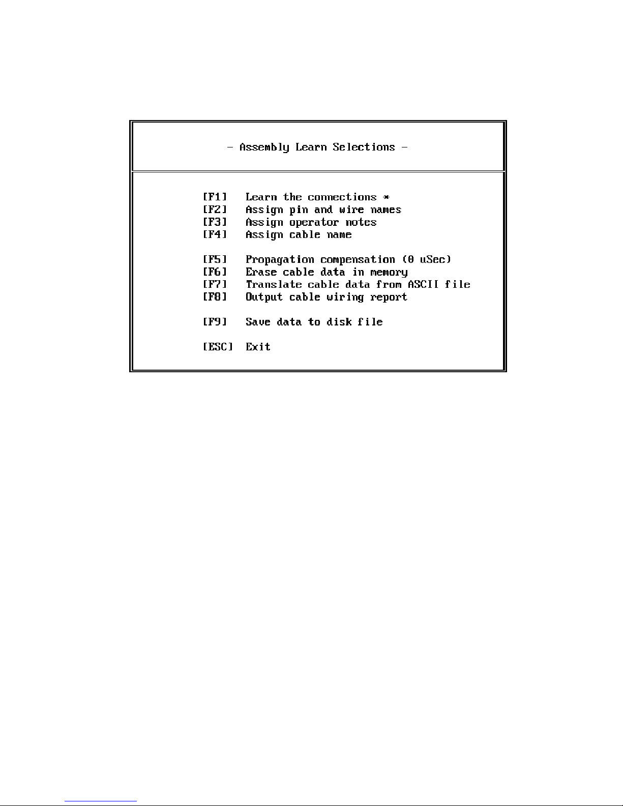
Figure 12 - Assembly Learn Menu
Autolearning the Connections
Pressing [F1] from the Assembly Learn menu causes the System to automatically learn
each of the connections for anything that is connected to the Test System at the time.
Once the connections are learned, an asterisk (*) appears to the right of the [F1] selection
so that you are reminded that the connections have been learned.
Assigning Pin and Wire Names
Selecting [F2] from the Assembly Learn menu allows you to assign pin and wire names to
the units that you are testing. If you use this feature, the reports and error messages that
you get from the System will be much more useful to you.
There can be a pin name and wire name for each port of the Test System. Each name can
be up to 16 characters in length.
CheckSum Model G-50 Manual - Page 33
Page 36
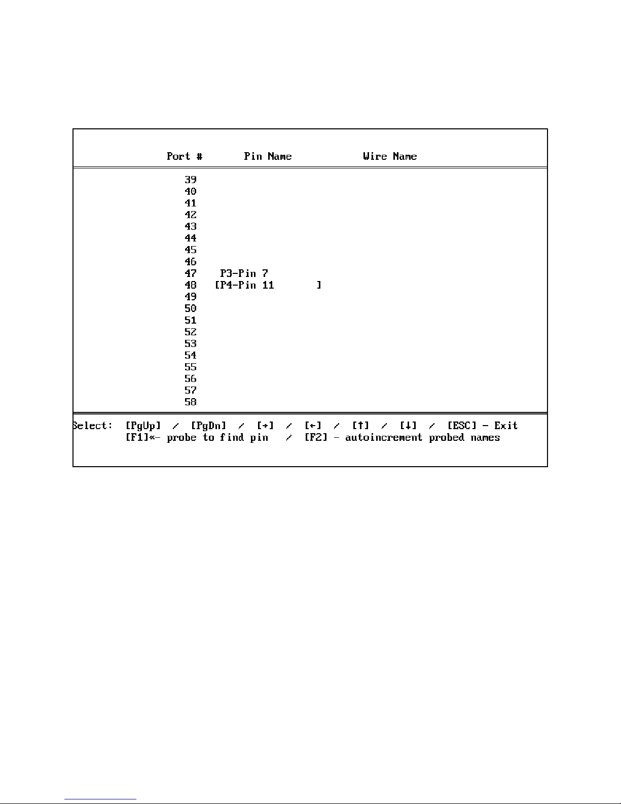
Once you have selected [F2], you see the Pin and Wire Name Entry screen (Figure 13).
Figure 13 - Pin and Wire Name Entry Screen
The Pin and Wire Name Entry screen works much like a spreadsheet. Use the page up and
down and the arrow keys to move the brackets to the row and column for adding the pin
or wire name. After you have entered a name, the System automatically moves to the
next position to make entry of a list faster.
When you have completed entry of pin and wire names, press [ESC] to move back to the
previous menu.
If you press the [F1] key, you can use the probe to locate the port number. With this feature you do not need to know the specifics of how the UUT is connected to your Continuity Test System. Simply press [F1]. [F1] toggles between probing on and off as indicated by a < < mark at the bottom of the display. If probing is enabled, each time the
System detects a probed point, it moves the entry area to that port. Using this method
you can probe each point and then type in its name.
CheckSum Model G-50 Manual - Page 34
Page 37

You may use the probe that comes with the Model G S-850 Fixture or your own probe.
The probe needs to be connected to the PC chassis to be effective since the System is
searching for a grounded input.
By selecting the [F2] option of the Pin and Wire Name Entry screen, you can select auto-increment of pin and wire names while probing. The System uses the pin name in the center of the screen as the base. When the next point is probed, it is assigned the same
name, but incremented by one. If the last digit of the pin name is alphabetic, it becomes
the next alphabetic character, moving from lower case to upper case. Note that no alphabetic characters are skipped, so it may be necessary to probe a point twice to skip over
unused pin names (such as an ‘i’ in some cases). If the last characters of the pin name are
numeric, they are incremented to the next numeric character. Pressing [F2] a second time
disables auto-increment.
Assigning Operator Instructions
Selecting [F3] from the Assembly Learn menu allows you to enter operator instructions.
Operator instructions are a way of giving information to the operator previous to each
test. The notes are presented to the operator and then a key is pressed to continue with
the test.
Operator instructions are presented each time a new assembly is tested, but are not
repeated for subsequent assemblies while testing a batch.
Operator instructions are handy for such things as connection information, special precautions, fixture adapter installation, or special instructions such as testing the assembly for intermittent failures. The comments screen can include line graphics such as - or = along
with corresponding corners and vertical single and double lines.
Comments are entered in the Operator Comments Entry screen shown in Figure 14.
CheckSum Model G-50 Manual - Page 35
Page 38
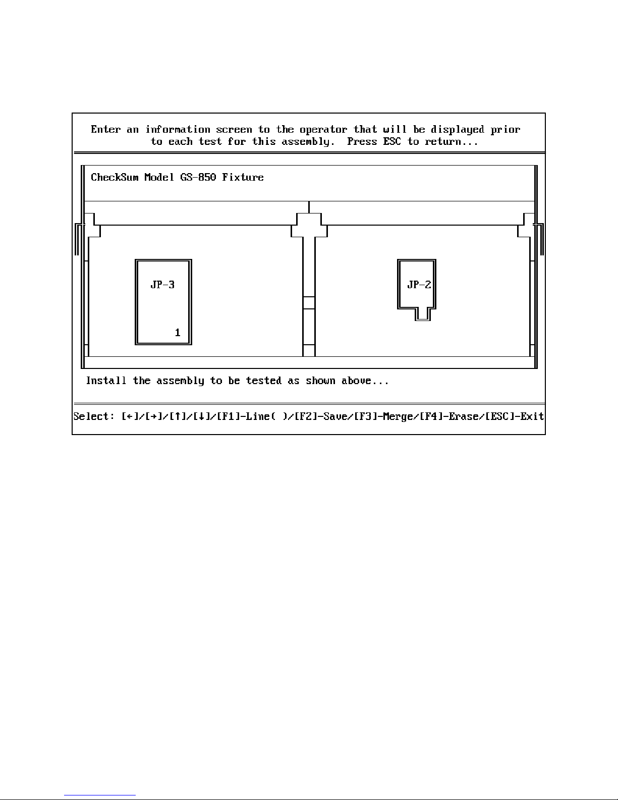
Figure 14 - Operator Comments Entry Screen
Use the arrow keys to move to the desired position for text or graphics. To enter text,
just type it. To erase a character position, use the space bar or backspace key.
To draw lines, use the [F1] key to toggle between the following:
( ) no lines
(-) single lines
(=) double lines
When in a line-drawing mode, the arrow keys draw lines in the direction indicated by the
arrow key. By turning lines on and off, you can achieve most line drawings. By redrawing
over lines, you can erase junctions to lines that you may have erased.
The drawing is saved with the spec data that you are creating at the time. In addition, the
[F2] key allows you to save the present screen to the disk for future recovery (for example, if you would like to read it into another spec file) rather than recreating it. The
drawing is saved as the name you specify with an extension of .CMT.
CheckSum Model G-50 Manual - Page 36
Page 39

The [F3] key allows you to merge a comment file on the disk (created with the [F2] option) with the screen presently shown. Any non-space character in the disk file overwrites
those at the same position on the display. Other characters are left undisturbed. To read
a file, enter the name. The System automatically adds the .CMT extension.
By merging the appropriate files, you can make outlines as necessary, then add text to
describe additional instructions. Other active keys are given below:
[Alt]-[F3] unmerges the specified file name
[F10] shifts the displayed figure one place to the right
~ left triangle
‘ right triangle
[Home] moves cursor to extreme left
[End] moves cursor to extreme right
[PgUp] moves cursor to top
[PgDn] moves cursor to bottom
[F4] erases the display
Assigning the Cable Name
Selecting [F4] from the Assembly Learn menu allows you to type in a descriptive name for
the cable. Any alphanumeric text up to 32 characters in length is allowed.
The cable name shows up in the File Select menu and on any cable reports that are
generated.
Propagation Compensation
Selecting [F5] from the Assembly Learn menu allows you to set a propagation delay for
the cable. If your cable is extremely long or is highly capacitive, it may be necessary to
use this feature. The System delays the requested time after stimulating a port, and
before measuring any of the other ports.
The time delay is approximate and varies depending on the type of computer that you are
using. For each uSec that you request, the System is commanded to perform an "I/O
Read" instruction. For most machines, this instruction sequence requires one to two uSec.
It should not be necessary to use a delay of more than one or two uSec.
CheckSum Model G-50 Manual - Page 37
Page 40

Erasing Cable Data
Selecting [F6] allows you to erase the cable data that is stored in memory. This option will
not destroy any cable data on the disk. It presents a warning message so that you will not
accidently lose any work that you have done and not saved.
Learning Cable Data from a File
Selection of [F7] allows you to read cable information that has been created elsewhere.
For example, you may wish to use a word processor or general-purpose editor to describe
a cable. This option allows you to read in that file and convert it into the internal format
used by CheckSoft Software.
The text file can contain the cable name, pin names, and wire names for a cable. The file
is based on the use of several keywords which are NAME:, ASSIGN:, TO:, FROM:, and
COM:. The ASCII input file is of the form:
! - An exclamation point is used to start a comment. Everything after it on the line is ignored.
Blank lines are ignored.
NAME: the cable name
ASSIGN: "pin name" (wire name) {port}
Use of the Assign keyword is completely optional, but can be used to associate pin
names or wire names with ports. This makes the rest of the file device-independent.
Pin name, wire name and port can come in any order. The parameters are all
optional. You should make sure that the ports are associated with a pin or port
before or at the same time the port is used.
FROM: parameters are the same as assign.
FROM is used to tell the origin of each pin. It is followed by one or more TOs. It is
not necessary to have a FROM for every connected pin. The program fills out the
table for the other direction of each TO.
CheckSum Model G-50 Manual - Page 38
Page 41

TO: parameters are the same as assign.
TO is used to tell which pins each port goes to.
COM: (or *) describes a line of operator comments.
Figure 15 shows an example of a text file used to define a cable.
! This is a cable definition for a simple cable
name: Cable PN 123-434
com: Connect cable to be tested to fixture connectors com: ‘con3’ on left and ‘con1’ on right.
com:Ensure adapter #9 is on left
com:Ensure adapter #2 is on right
assign: {1} "Pin 1" (RTS)
assign: {2} "Pin 2" (CTS)
assign: {3} "Pin 32"
from: "Pin 1" to: "Pin 32"
from: "Pin 2" to: "Pin 32"
Figure 15 - Sample Text File
In Figure 15, a cable is described that has connections from Pin 1 to Pin 32, and also from
Pin 2 to Pin 32. The cable’s Pin 1 is connected to port 1 of the SR-500, Pin 2 to port 2
and Pin 32 to port 3. The signal at Pin 1 is named RTS and the signal at Pin 2 is named
CTS. The System figures out all of the resulting paths for you. For example, Pin 1 and
Pin 2 are connected together through Pin 32 even though though the connection is not explicitly stated. The example also includes some operator instructions describing how the
fixture should be set up and the cable connected.
CheckSum Model G-50 Manual - Page 39
Page 42

Printing Wiring Information
Selection of [F8] from the Assembly Learn menu allows you to print out a report of how a
cable is wired.
The report goes to the destination selected in the Setup/Configuration menu. If CON is
selected there, the report is displayed on your CRT. Other choices include your PC’s
printer or a disk file. The format of the report is shown in Appendix B.
The test report includes the Cable ID (the optional cable name assigned when the cable is
learned). It also contains an identity of the cable tester.
Each connection is listed in the report. Also, all of the connections from each pin are
listed so that the report serves as a useful reference for repairing or building a cable. The
report can be configured to just display each connection one time by choosing "Compact"
from the Report Configuration menu.
Saving Cable Data on the Disk
Selection of [F9] from the Assembly Learn menu allows you to save the information about
the cable you have learned onto a hard disk or floppy disk drive.
After selection of [F9], you are prompted to enter a file name. Enter a file name with up
to eleven characters that do not include spaces or special characters such as colons or
periods. Your DOS manual describes valid file names for your version of DOS.
After the name is entered, the System saves the file in the path defined in the Setup/Con -
figuration menu.
The file is written in binary. Consequently, you cannot look at it with normal editors.
(You can look at it with some editors, but it probably won’t make any sense to you.) The
advantage of this storage method is that the file is very compact and also fast to load and
execute.
The file contains a list of the connections, the cable name, operator comments, pin and
wire names, and the number of SR-500 I/O Modules configured into your System.
CheckSum Model G-50 Manual - Page 40
Page 43
Locating a Pin
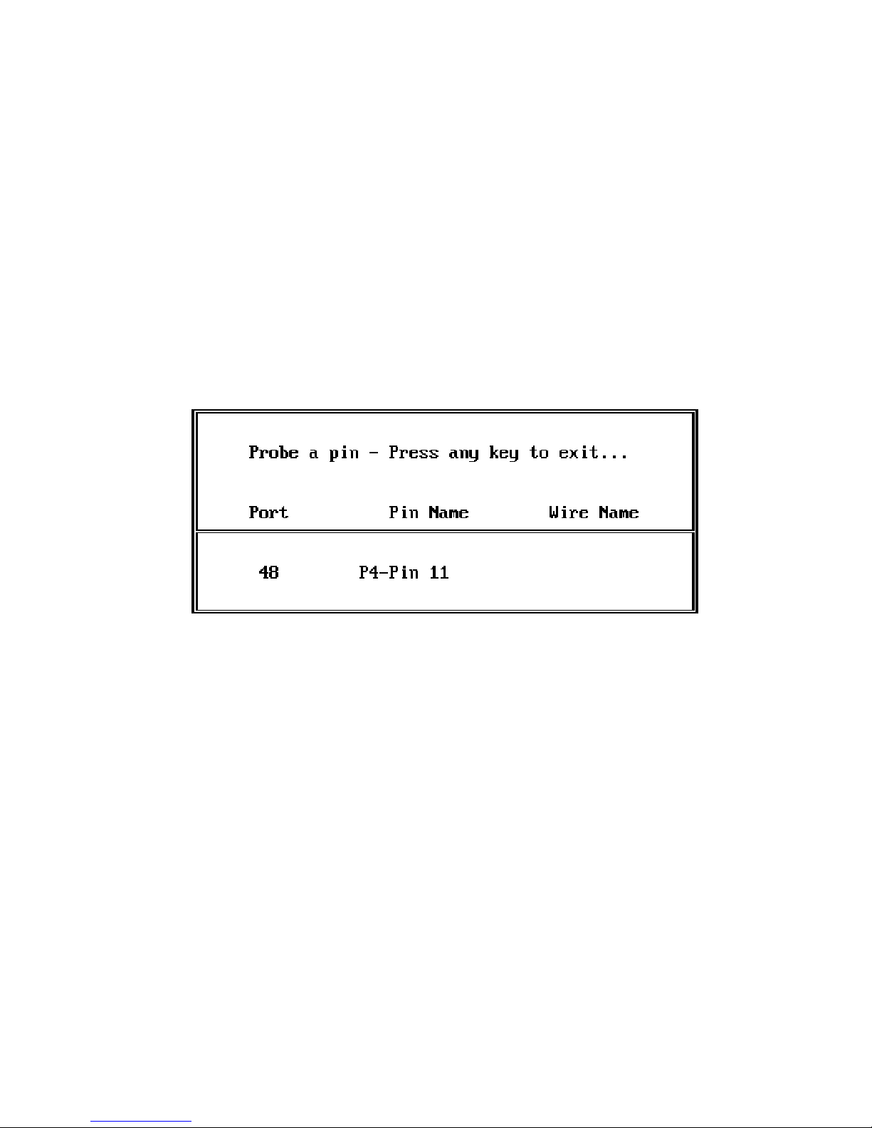
Locating a pin is used for determining the identity of a particular pin in your cable or fixture.
Pressing [F3] from the System menu invokes this function. The locating display is shown
in Figure 16.
Figure 16 - Pin Locating Display
Simply probe a pin to find its identity. If a pin name and wire name have been assigned,
they are displayed as well.
You may either use the probe that comes with the Model GS-850 Fixture or your own
probe. The probe needs to be connected to the PC chassis to be effective since the System is searching for a grounded input. The GS-850 probe jack is grounded for you by the
ground cable to the computer.
When you move the probe to another pin in the cable, the new pin identity is displayed.
CheckSum Model G-50 Manual - Page 41
Page 44
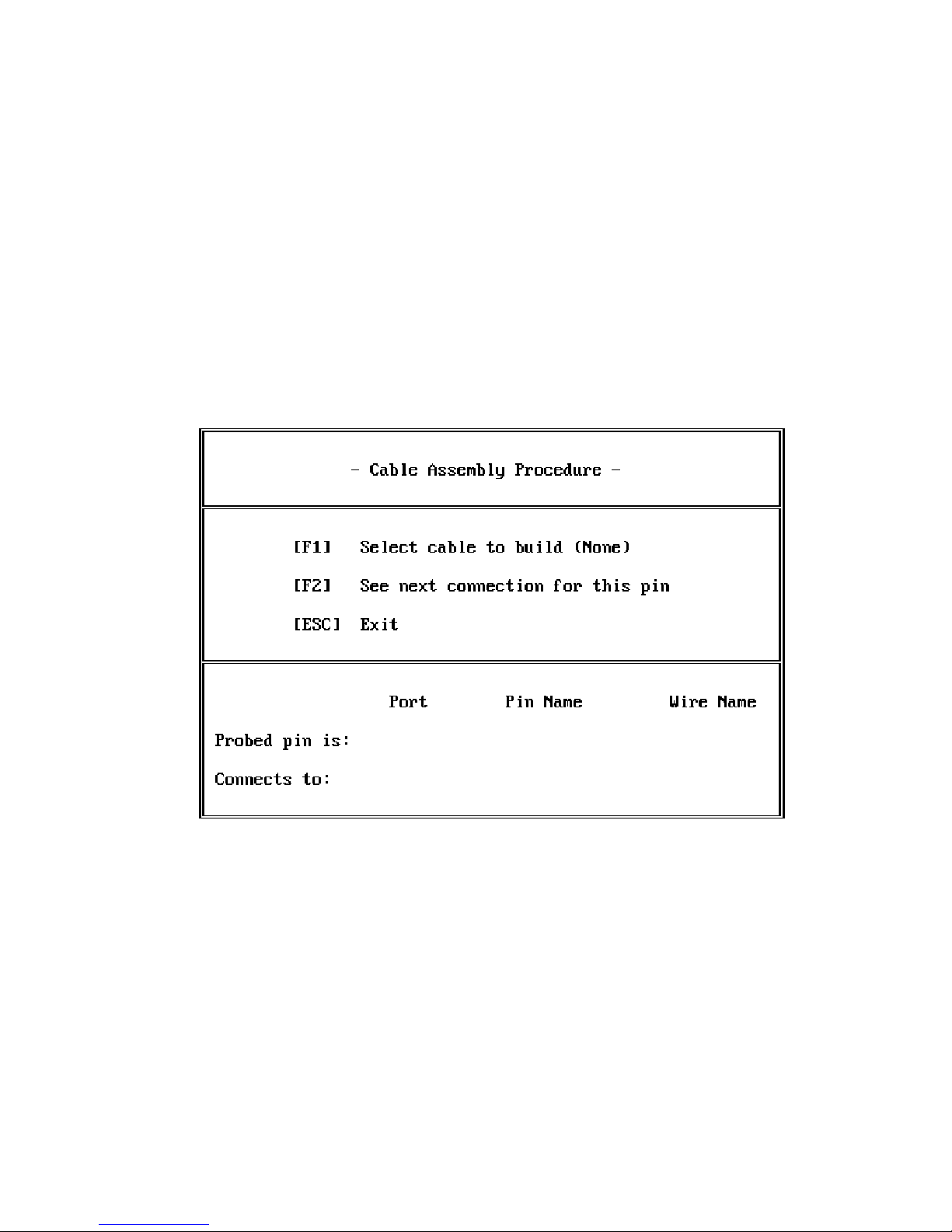
Assemble a Cable
The cable assembly function is an aid for building or repairing cables. It provides the
capability to locate a pin, then display the connections for that pin.
To invoke cable assembly, select [F4] from the System menu. You are then presented
with the Cable Assembly display as shown in Figure 17.
The System uses whatever cable definition is presently in memory. If you would like to
load another cable definition, select [F1]. You may then type in the name of a file containing a file definition.
To perform an assembly, probe the wire that you would like to connect. You may either
use the probe that comes with the Model G S-850 Fixture or your own probe. The probe
needs to be electrically connected to the PC chassis to be effective since the System is
searching for a grounded input.
Figure 17 - Cable Assembly Display
CheckSum Model G-50 Manual - Page 42
Page 45
Once a pin has been probed, the port number, pin name and wire name of the probed pin
appear in the "Probed pin is:" row of the display.
The "Connects to:" row of the display shows a description of the destination for the
probed pin. If there is another destination, pressing [F2] advances to the next destination.
Selecting [ESC] returns to the System menu.
System Self-Test
The System self-test is a diagnostic utility that provides you with confidence that your System is operating properly. Since each port on the SR-500 is bidirectional, the individual
port outputs can be changed to each state and then be measured.
Consequently, the self-test can locate virtually all faults that might occur.
Note
Ensure no cables are connected during the self-test. If cables are connected, you may get
incorrect test results.
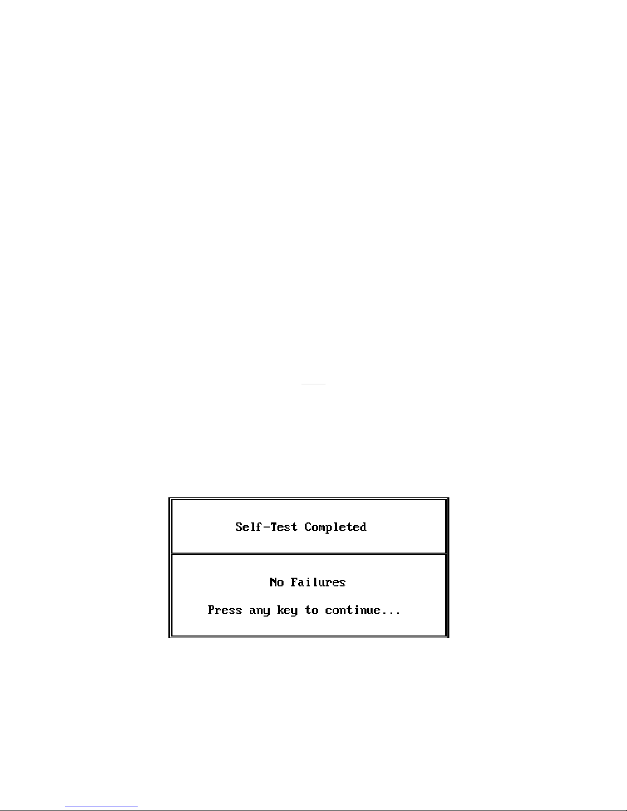
To initiate a self-test, select [F5] from the System menu. When the test is complete, you
will see a results summary as shown in Figure 18.
Figure 18 - Self-Test Result Display
If there are any failures, prior to the Self-Test Result display you will receive the Self-Test
Failure display as shown in Figure 19.
CheckSum Model G-50 Manual - Page 43
Page 46
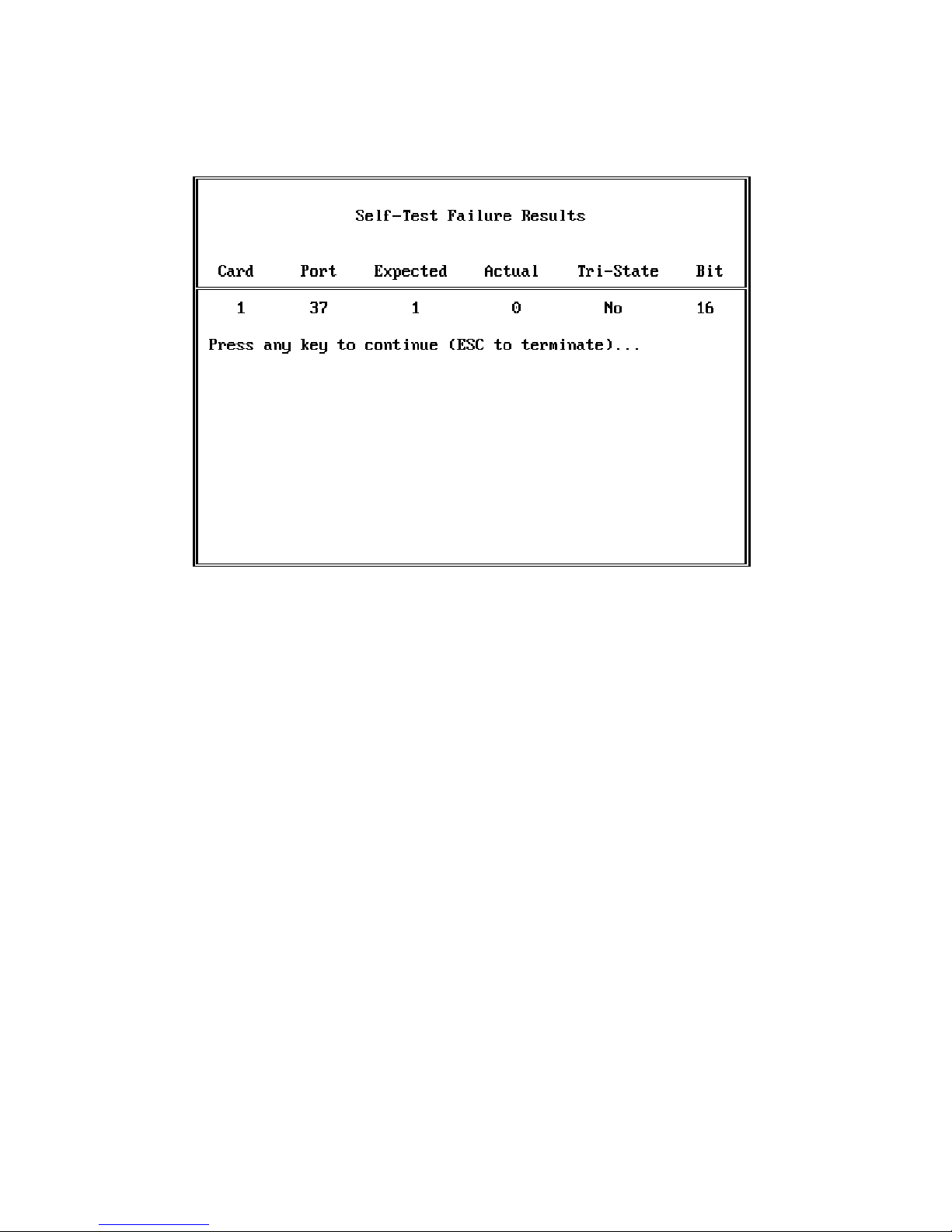
Figure 19 - Self-Test Failure Display
The test outcome expresses the state of the hardware at the time of the failure:
"Card" tells which SR-500 is involved in the failure. The card number is the same as
that jumpered on the BOARD SELECT pins of the SR-500.
"Port" tells which port (I/O pin) of the SR-500 failed.
"Expected" shows the desired test result.
"Actual" shows the measured value.
"Tri-State" shows whether the output was tri-stated or active at the time of the failure.
"Bit" shows which decimal bit position on the output byte has failed.
If you see massive self-test failures, it is likely to be an installation or compatibility problem. If you see one (or a few) repeatable failures, you can suspect an SR-500 hardware
failure. In this case return the SR -500 to CheckSum for analysis.
CheckSum Model G-50 Manual - Page 44
Page 47
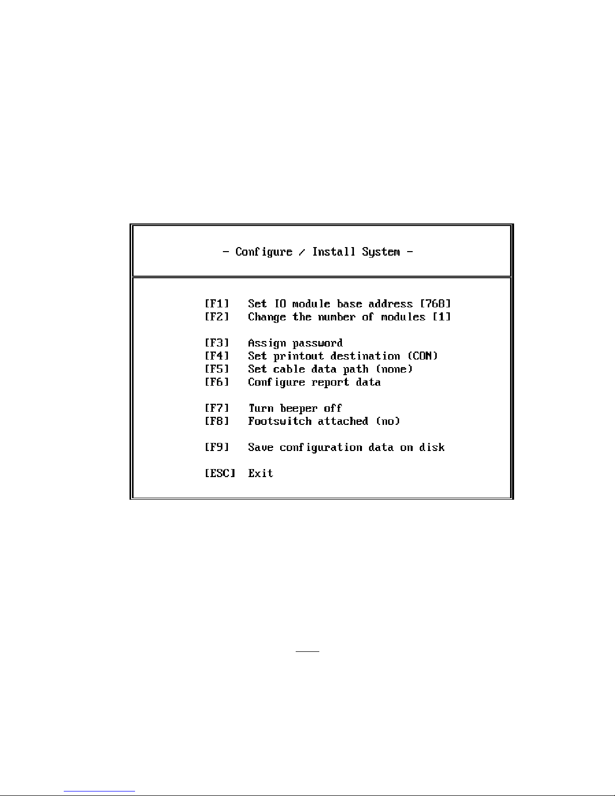
Configure / Install System
The configuration menu of the System is used to either temporarily or permanently
change the configuration of the System.
Figure 20 - Configure / Install System Menu
[F1] and [F2] are used to specify the hardware configuration of the System. [F1] is used
to set the I/O channel base address used by the SR-500s. It also shows the present setting
in decimal. [F2] defines how many SR-500s are installed in the System. For more detail
about these options, see "Solving Installation Problems" in the Appendix of this manual.
If you have a large number of SR-500s in your system but are only using some of the
lower numbered ones, temporarily setting the number of I/O modules to reflect the number of the highest card that you are actually using will cause the tests to execute faster.
Note
CheckSum Model G-50 Manual - Page 45
Page 48

[F3] is used to assign a System password. The password can be used to prevent unauthorized modification of spec files. When a password is active, the operator must enter
the password before having access to the Assembly Learn Selection screen. Consequently,
spec files cannot be generated or modified without the password.
If a password exists, the System prompts you to enter it before changing to a new
password. It also asks you to enter the new password twice before accepting it. Terminate each entry with the [Enter] key.
The password can be up to twelve characters long and can contain any normal keyboard
characters. If you assign a password of nothing (just the [Enter] key), password protection
is disabled. The system does not discriminate between upper- and-lower case characters
in the password.
[F4] is used to specify the destination of reports from the System. You may toggle between several choices. If CON(sole) is selected, the reports will go to the PC’s CRT display. If PR N is selected, the reports will go to your printer. You can also individually
select the COM and LPT ports if you have more than one printer.
You may choose FILE.TXT to send the output to a disk file by this name. Note that if
this option is used, the file is saved in the same directory as the CheckSoft Software. It
does not use the data path. After the file is saved you can leave CheckSoft Software and
rename and/or move the file with the DOS COPY command. If you save more than once
to FILE.TXT, the file is appended with the new data. Because of this, you can use
FILE.TXT to accumulate results, then periodically you may archive these results and start
over.
[F5] is used to set the path for the cable data files that are saved and retrieved. If you do
not specify anything here, the files will be stored in the same directory and media as the
CheckSoft Software. If you use this feature, make sure that you include a "\ " or ":" at the
end. Examples of proper data paths are "\ CHECKSUM\ DATA\ ", "B:", and
"A:\ DATA\ ". If you do not want to use a path (the spec data files reside in the same
directory as the CheckSum software), press [F5], then [Enter]. The System will then
reflect a password of ‘None.’
[F6] is used to configure the reports generated by the System. When you select [F6], you
are presented with the Report Configuration menu. The choices made in the Report Con-
figuration menu can be saved on the disk by use of [F9] from the Setup/Configuration
menu.
CheckSum Model G-50 Manual - Page 46
Page 49

[F7] is used to turn the System beeper on and off. The beeper is used to let you know
when an error occurs or you have probed a point. [F7] toggles the beeper either on or off
for all uses of the beeper in the System.
[F8] is used to specify that you have connected a foot switch to the System. A foot switch
is available from CheckSum that connects to an unused printer port on your PC. When
the foot switch is activated, it performs the same function as the [F1] key on the keyboard.
Pressing [F8] toggles between none and the various printer ports (LPT1, LPT2,...) on the
PC. Toggle through the various options until the display shows the printer port to which
you have connected the foot switch.
[F9] is used to save the configuration selections that you have made to the disk drive.
When you save the configurations, each time you restart CheckSoft Software you will not
need to reconfigure your System. The configuration file is transparent to you. It is named
"$CONFIG$.CSM" and is stored in the same directory as the CheckSoft Software. Selection of [F9] also saves the printout configuration parameters.
[ESC] causes a return to the System menu.
Report Configuration
The Report Configuration menu is accessed by selecting [F6] from the Setup / Configuration menu. It allows you to determine the format of reports generated by the System.
CheckSum Model G-50 Manual - Page 47
Page 50
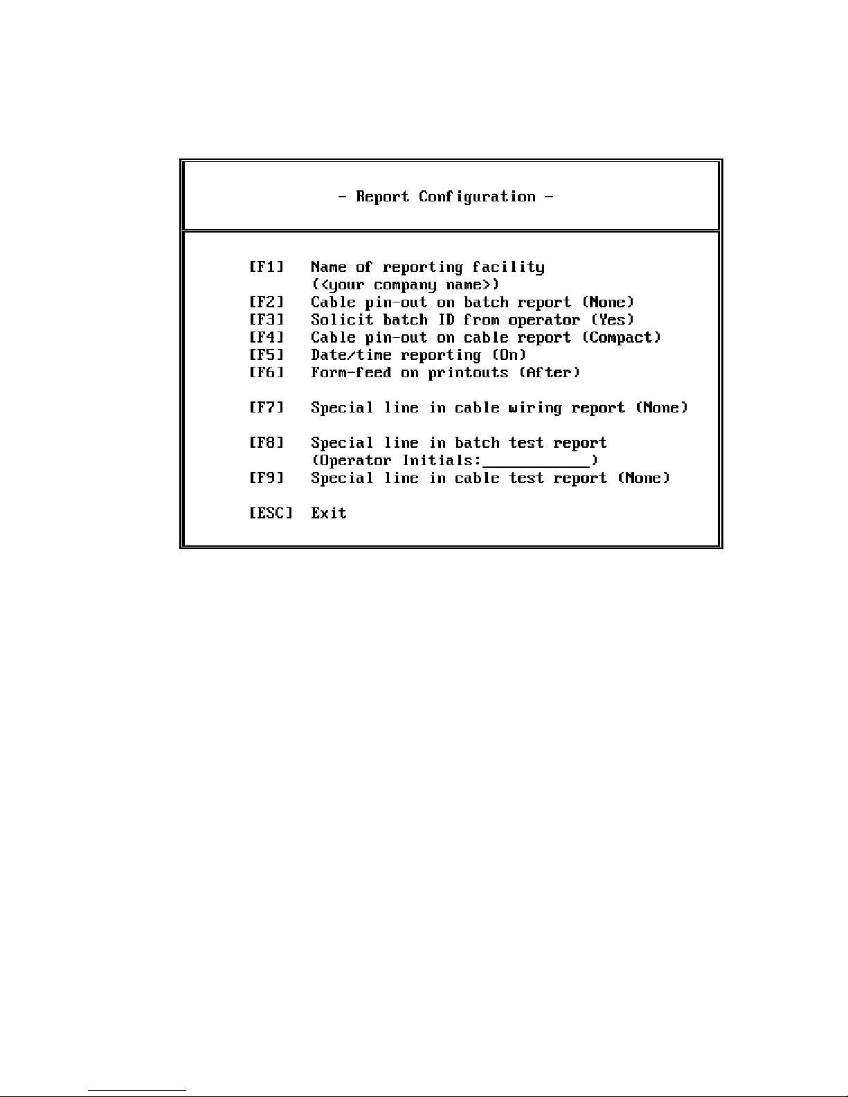
Figure 21 - Report Configuration Menu
[F1] is used to enter the name of your company or organization. This name (up to 32
characters) then appears on all of the reports generated by the System. If nothing is
entered, the line does not appear on the reports.
[F2] is used to specify whether to print out cable wiring information in batch reports.
Pressing [F2] toggles between three selections - None, Compact, and Full. If Compact is
selected, each connection in the cable is shown once. If Full is selected, the destination of
each pin is shown on the left side of the listing. Consequently, each connection is shown
twice and as a result the report is much longer. Full is valuable if you are using the report
to help troubleshoot cables since it is easier to find the destination of each pin.
[F3] is used to select whether the System asks the operator to type in the name of a batch
prior to printing the batch report. If this feature is enabled, and the operator types in the
batch identification, a line on the report appears titled "Batch ID:" followed by the
operator entry. In addition, if this feature is enabled and a batch report is not requested
at the end of testing a batch, the System verifies that this is the operator’s intent, since the
data about the batch could be accidently lost.
CheckSum Model G-50 Manual - Page 48
Page 51

[F4] specifies how the cable wiring is printed in a cable wiring report. Pressing [F4] toggles between Compact and Full. The meaning of Full and Compact are defined above in
the [F2] description of this menu.
[F5] is used to specify whether to print the date and time on the System reports. If
enabled, the date and time (in 24-hour format) when the report is printed is included in
the report.
[F6] configures page breaks while printing reports to a printer (PRN, COM, or LPT) port.
Pressing [F6] toggles between None, Before, After and Before/After. In the default
mode, After, the System prints a form feed after each report to set the printer for the next
report to be on a new sheet of paper.
[F7], [F8], and [F9] are used to place a special line of text in the respectively named
reports. You may enter a line of up to 32 characters. If nothing is entered, ‘None’ is displayed and the reports do not contain this special line. If something is entered, it is placed
in the header of the report, left-justified. If the line contains a colon, the information
before the colon (including the colon) is placed in the left column, and the information
after the colon is placed in the second column aligned with the other header items.
Special lines of text can be used for any special information that you would like included
in the reports. For example, if you would like the operator to initial each batch test
report, you would select [F8], then type in ‘Operator Initials:__________’. The outcome
of this entry is shown in the example batch report in the Appendix of this manual.
[F9] returns to the Configure / Install System menu.
CheckSum Model G-50 Manual - Page 49
Page 52

CheckSum Model G-50 Manual - Page 50
Page 53

Wiring Diagrams
Appendix A
CheckSum Model G-50 - Appendix Page 1
Page 54
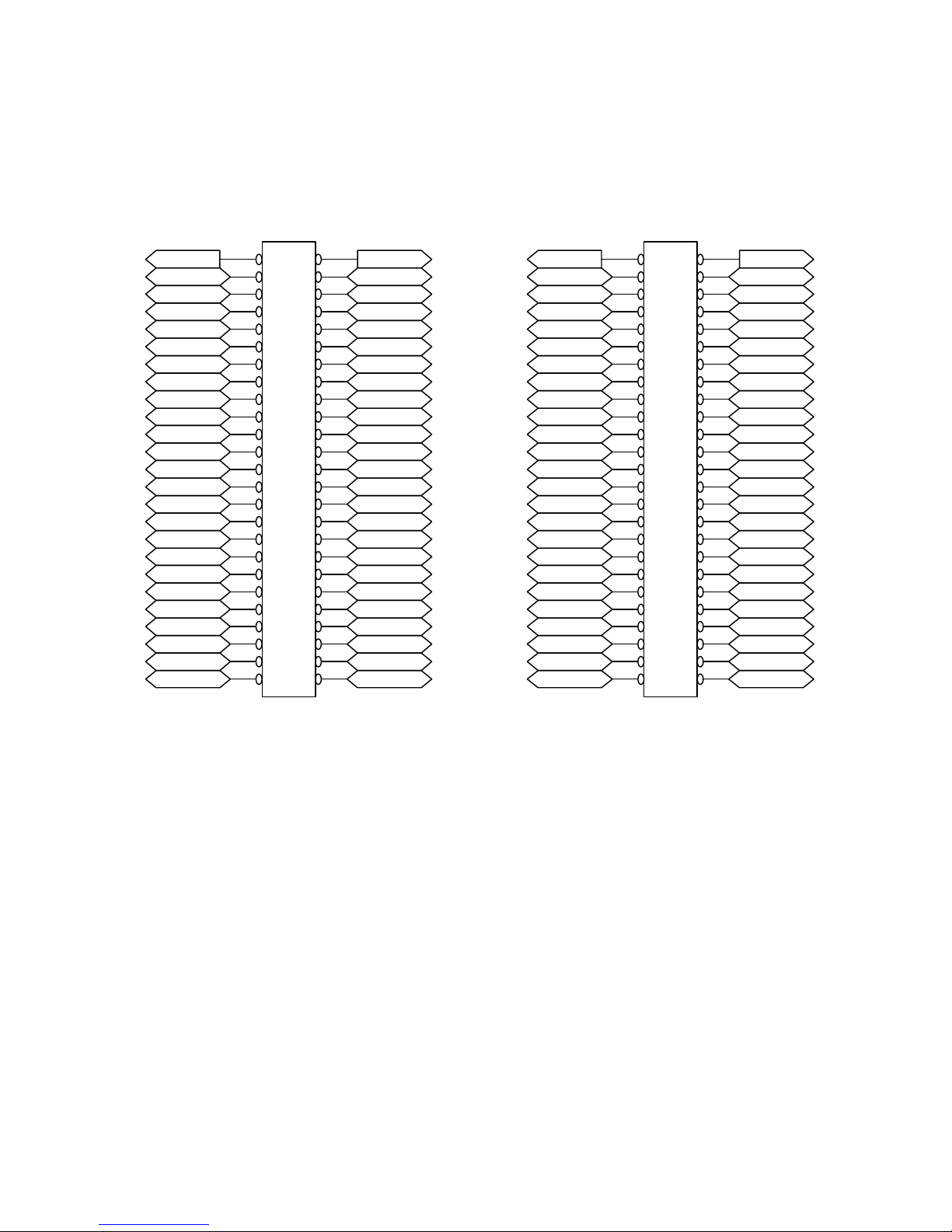
UUTVCC1
Port 48
Port 46
Port 44
Port 42
Port 40
Port 38
Port 36
Port 34
Port 32
Port 30
Port 28
Port 26
Port 24
Port 22
Port 20
Port 18
Port 16
Port 14
Port 12
Port 10
Port 8
Port 6
Port 4
Port 2
JP3
JP4
4950
4748
4546
4344
4142
3940
3738
3536
3334
3132
2930
2728
2526
2324
2122
1920
1718
1516
1314
1112
910
78
56
34
12
UUTGnd1 UUTVCC2
Port 47
Port 45
Port 43
Port 41
Port 39
Port 37
Port 35
Port 33
Port 31
Port 29
Port 27
Port 25
Port 23
Port 21
Port 19
Port 17
Port 15
Port 13
Port 11
Port 9
Port 7
Port 5
Port 3
Port 1
Port 96
Port 94
Port 92
Port 90
Port 88
Port 86
Port 84
Port 82
Port 80
Port 78
Port 76
Port 74
Port 72
Port 70
Port 68
Port 66
Port 64
Port 62
Port 60
Port 58
Port 56
Port 54
Port 52
Port 50
4950
4748
4546
4344
4142
3940
3738
3536
3334
3132
2930
2728
2526
2324
2122
1920
1718
1516
1314
1112
910
78
56
34
12
UUTGnd2
Port 95
Port 93
Port 91
Port 89
Port 87
Port 85
Port 83
Port 81
Port 79
Port 77
Port 75
Port 73
Port 71
Port 69
Port 67
Port 65
Port 63
Port 61
Port 59
Port 57
Port 55
Port 53
Port 51
Port 49
Viewed as facing component side of PCB
Figure A1 - Model SR-500 Pin-Out
CheckSum Model G-50 - Appendix Page 2
Right Angle Header
Page 55

Sample Reports
========================================
Cable Test Report
Testing Facility: Delro Inc. - Dept 32
Cable ID: Cable PN 123-434
Failures: 3
Test Date: 9/10/90
Time: 11:28
Cable Tester: CheckSum Model G-50
Appendix B
========================================
Port Pin Name Wire Name Port Pin Name Wire Name
1 Pin 1 RTS < > 3 Pin 32
2 Pin 2 CTS < > 3 Pin 32
3 Pin 32 <=> 4
End of data
Report showing unexpected opens from port 1 to port 3 and port 2 to port 3. It also
shows a short from port 3 to port 4.
Figure A2 - Cable Test Report With Failures
CheckSum Model G-50 - Appendix Page 3
Page 56

========================================
Cable Test Report
Testing Facility: Delro Inc. - Dept 32
Cable ID: Cable PN 123-434
Failures: 0
Test Date: 9/10/90
Time: 11:28
Cable Tester: CheckSum Model G-50
========================================
Port Pin Name Wire Name Port Pin Name Wire Name
Test Passed, no failures...
End of data
Figure A3 - Cable Test Report With No Failures
CheckSum Model G-50 - Appendix Page 4
Page 57

========================================
Cable Wiring Report
Testing Facility: Delro Inc. - Dept 32
Cable ID: Cable PN 123-434
Report Date: 9/10/90
Time: 11:28
Cable Tester: CheckSum Model G-50
========================================
Port Pin Name Wire Name Port Pin Name Wire Name
1 Pin 1 RTS <=> 2 Pin 2 CTS
1 Pin 1 RTS <=> 3 Pin 32
2 Pin 2 CTS <=> 1 Pin 1 RTS
2 Pin 2 CTS <=> 3 Pin 32
3 Pin 32 <=> 1 Pin 1 RTS
3 Pin 32 <=> 2 Pin 2 CTS
End of data
Figure A4 - Cable Wiring Report
CheckSum Model G-50 - Appendix Page 5
Page 58

========================================
Batch Test Report
Testing Facility: Delro Inc. - Dept 32
Cable ID: Cable PN 123-434
Batch ID: Order No. 43-54W
Operator Initials: _________________
Number Tested: 10
Failures: 1
Yield 90%
Test Date: 9/10/90
Time: 11:28
Cable Tester: CheckSum Model G-50
========================================
Figure A5 - Batch Test Report
CheckSum Model G-50 - Appendix Page 6
Page 59

Appendix C
In Case of Problems
If you suspect problems in the operation of your Cable Test System, you should run the
self-test that is available from the System menu. Directions for running the self-test are included in the Operating Instructions section of this manual.
If the self-test reports a number of errors, it is likely to be caused by an installation problem such as improper jumpering.
If a single port (pin) or group of ports give errors that are the same each time you run the
test, there may be a failed component on the SR-500. If this is the case, you may want to
inspect the SR-500 for damage or return it to CheckSum for analysis.
Ensure that the BOARD SELECT jumpers are installed properly. There should be one
BOARD SELECT jumper on each SR-500 Module. If you have more than one SR-500,
they must be at unique sequential addresses beginning with one.
The SR-500s do not use interrupts or DMA channels so there can be no conflicts in these
areas.
If you still have problems, there may be a conflict on the PC’s I/O channel. The SR-500
uses 32 sequential byte addresses on the I/O channel. The default Base Address is 768
(300 hex). I/O space up to 799 (31F hex) is used by the SR-500. These addresses are
reserved by IBM for use with the prototype card so there should be no conflicts with
standard PC hardware.
Note
Some Leading Edge brand computers use Base Address 768 for their own internal purposes. Rejum pering the CheckSum I/O Module to Base Address 512 will allow the
Model R-50 to work in these computers.
To determine if there are address conflicts, you may wish to remove suspected cards from
your computer and try the SR -500 Modules again. Don’t forget to remove power and observe static-sensitive rules when you do this!
CheckSum Model G-50 - Appendix Page 7
Page 60

In the event another card in the PC is using this I/O space, you may rejumper that card to
another spot. Otherwise, you may wish to rejumper the SR-500 to another base address.
Normally, if 768 doesn’t work, you might want to try 512 as the second choice. To do so,
add a jumper to ADR8.
The following table shows how the ADR jumpers are used:
Jumper Pair Address Bit
ADR5 32 (20 hex)
ADR6 64 (40 hex)
ADR7 128 (80 hex)
ADR8 256 (100 hex)
ADR9 512 (200 hex)
Table A1 - SR-500 Base Address Jumpers
The base address is the sum of the above numbers for each of the ADR5-ADR9 jumpers
which are REMOVED. For example, in the default case, there are no jumpers on ADR8
and ADR9 so the Base Address is 256 + 512 = 768.
The SR-500s all must be set to the same base address.
When you change the SR-500 base address, you must also go to the CheckSoft Setup/Configuration menu and change the corresponding base address to match the jumpered base
address of the I/O Modules.
CheckSum Model G-50 - Appendix Page 8
Page 61

The following table shows how the IBM PC/XT and AT use their I/O ports:
User PC/XT AT
DMA Controller 000-00F 000-01F
Interrupt Controller 020-021 020-03F
Timer 040-043 040-05F
PPI 060-063 n/a
Keyboard n/a 060-06F
DMA Page Register 080-083 080-09F
NMI Mask Register 0A 070-07F
Interrupt Controller 2 n/a 0A0-0BF
DMA Controller 2 n/a 0C0-0DF
Math Coprocessor n/a 0F8-0FF
Joystick/Game Controller 200-20F 200-20F
Expansion Unit 210-217 n/a
Parallel Printer n/a 278-27F
Serial Port (Primary) 3F8-3FF 3F8-3FF
Serial Port (Secondary) 2F8-2FF 2F8-2FF
Prototype Card 300-31F 300-31F
Fixed Disk 320-32F 1F0-1F8
Parallel Printer (Primary) 378-37F 378-37F
SDLC 380-38F 380-38F
Bisynchronous Com. n/a 3A0-3AF
Mono Adapter/Printer 3B0-3BF 3B0-3BF
CGA Adapter 3D0-3DF 3D0-3DF
Diskette Controller 3F0-3F7 3F0-3F7
Table A2 - Computer I/O Port Assignment
CheckSum Model G-50 - Appendix Page 9
Page 62

CheckSum Model G-50 - Appendix Page 10
Page 63

Appendix D
Error Messages
Errors that could occur while reading or writing to and from the computer’s disk include:
Error Number Error Description
Error 3 Path not found
Error 4 Too many files open
Error 5 File access denied
Error 12 Invalid file access code
Error 15 Invalid drive number
Error 97 Incorrect spec file revision
Error 99 Not a valid spec data file
Error 100 Disk Read error
Error 101 Disk out of space
Error 103 File Open error
Error 150 Disk is write-protected
Error 152 Drive is not ready
Error 156 Disk seek error
Error 162 Hardware failure
Table A3 - File Error Messages
CheckSum Model G-50 - Appendix Page 11
Page 64

CheckSum Model G-50 - Appendix Page 12
Page 65

Appendix E
Glossary
Assembly - The unit being tested. A typical assembly might be a cable, harness, back-
plane, or circuit assembly.
Base Address - Jumpers on the Model SR-500 that allow the installer to specify where in
the computer’s I/O address space the Model SR-500 resides. The base address must not
conflict with other hardware installed in the computer.
Batch - A collection of UUTs that share common spec data. Batches might be a shipment of assemblies that need testing or a single assembly with a number of common identical circuits to be tested.
Batch Report - A report describing the outcome of testing more than one UUT with common spec data. The batch report includes yield (percent OK), date and time of the test,
batch identification, tester ID, testing facility name, and optionally the spec data for the
batch.
Board Select - A header on Model SR-500s that allows the installer to set the module’s
identity to the computer. Each module has eight possible module select positions. Each
module that uses the same base address must have a unique module select position.
Cable Name - An optional name that can be assigned to spec data that identifies the
UUT. The assembly name can be up to 32 characters in length. The assembly name is included in reports about the UUT and in some of the System menus.
Cable Data - Same as Spec Data.
CheckSoft Software - Software that runs on the PC to perform the testing. CheckSoft
Software is menu-driven and runs in the DOS environment.
Configuration Data - Information saved on disk that tailors the System’s setup to a particular application so that the System does not need to be configured each time it is used.
The configuration data is specified and saved with selections in the Configure/Install Sys-
tem menu.
CheckSum Model G-50 - Appendix Page 13
Page 66

Data Path - A string of characters added to the beginning of the file name when spec data
is being retrieved or saved. The data path can be used to specify a device or directory.
For example, if the data path were set to ‘B:\DATA\’, all of the spec data would be saved
and retrieved from the directory ‘DATA’ on disk drive B.
I/O Addressing - The internal bus used for controlling hardware with the
8086/8088/80286/80386 series of computers.
Model CBX Adapter - An optional adapter that converts the 50-pin ribbon cable connectors on the end of the cables coming from a CheckSum I/O Module to discrete wire screwdown terminals.
Model G-50 Continuity Test System - A Test System consisting of one or more Model
SR-500 Continuity I/O Modules, CheckSoft Software, and cabling to the UUT. These elements are installed into the user’s PC for testing assemblies.
Model GS-850 Fixture - An optional Fixture that connects between the Model SR-500
Continuity I/O Modules and the UUT. It allows the user to quickly and reliably change
"adapters" for interfacing to different UUTs.
Model SR-500 Continuity I/O Module - The electronics for the Test System that are installed in the PC. Each SR-500 Module contains 96 ports for testing the UUT. A single
System can have up to eight SR-500s.
Model TR-3 Fixture - An optional Bed-of-Nails Fixture that connects between the Model
SR-500 Continuity I/O Modules and the UUT. This Fixture can be used for bare-board
or loaded assembly testing.
Model T-120 System Controller - An IBM AT-compatible computer available from
CheckSum that can be used in conjunction with CheckSum testing hardware and software.
Operator Comments (or Operator Instructions) - An optional screen of information that
can be displayed to the System operator when beginning the test of each type of UUT.
Operator comments can be used for various purposes such as to describe how to connect
the UUT to the System, which adapters to install, or special precautions for the UUT.
Pin Name - An optional string of characters assigned by the user that describe the connection to the UUT. Examples might be ‘J4 Pin 7a’ or ‘U7 Pin 3’. Each pin name can contain up to 16 characters. There can be a unique pin name for each tester port.
Ports - The test pins of the Model SR-500 Continuity I/O Module. Each port is connected to a particular test point of the unit-under-test.
CheckSum Model G-50 - Appendix Page 14
Page 67

Report Device - The computer device that will receive information from the computer.
The report device can be configured to be the CRT (CONsole), the printer (PRN), a file
on the disk (FILE.TXT), or other alternatives.
Reporting Facility - Name of the organization doing the testing. If the System is configured with a reporting facility, all of the reports contain a line with the facility name.
The reporting facility can be up to 32 characters long and is configured from the Report
Configuration menu.
Spec Data - Spec(ification) data describing how the UUT is tested. The spec data includes information about each connection such as the port numbers, and pin and wire
names. In addition, the spec data includes the assembly name.
Test Report - A report describing the outcome of testing a single UUT against its spec
data. This report includes information about each failed measurement (e.g., port numbers, pin and wire names), the test threshold, the facility name, and tester identification.
UUT - Unit-U nder-Test. The assembly being tested by the Test System.
Wire Name - An optional string of characters assigned by the user that describe the UUT.
Examples might be ‘Red Wire’ or ‘VCC Bus’. Each wire name can contain up to 16 characters. There can be a unique wire name for each tester port.
CheckSum Model G-50 - Appendix Page 15
Page 68

CheckSum Model G-50 - Appendix Page 16
Page 69

CheckSum Model G-50 - Appendix Page 17
Page 70

CheckSum Model G-50 - Appendix Page 18
 Loading...