

Page 1
Checkpoint Systems, Inc.
This device is certified for mobile applications in which the antennas used
for this transmitter must be installed to provide a separation distance of at
least 20 cm from all persons.
Ferrite cores:
1) Fair Rite P/N 73420 (Order No. 2865-000-202): 1 on each Light and
Buzzer cable with 2 turns through the ferrite.
2) Würth 742 71111: 1 ferrite on the RX/TX cable with one turn through the
ferrite.
3) Würth 7427122, KITAGAWA SFC-10, Fair Rite P/N 284760 (Order No.
0443806406) or GRFC-10: 1 ferrite on DC cable of the power supply with
three turns through the ferrite.
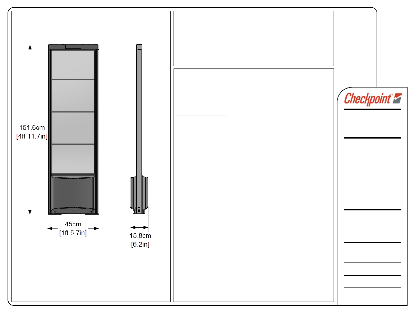
EVOLVE E10 2.0 RFID-Ready (RF) and RFID-enabled systems
Antenna Placement – FCC Region
With standard 410 EP series EAS tags, the maximum on-center aisle
width is 182cm [72 in] between antennas.
isle (3 pedestal) and Multi-Aisle Layouts are applicable for wider exits.
Dual A
The minimum distance between any door frame and antenna is 45.72cm [18 in].
Antenna Installation – Physical Requirements
Mounting:
Each antenna is mounted to the floor with two (2) anchor bolts.
Concrete: 1.3cm [0.5 in.] anchor bolts
Wood: 9.5mm [0.375 in.] lag bolts
Antennas ar e typically mounted by Checkpoint Field Servi ce personnel.
Wiring Routing Methods:
Floor:
• Conduit Size: 4cm [1.5 in.] diameter – rout e between each antenna
(ensure conduit access under frame) and to power supply location.
• Placement Constraints: Conduit must be placed 68.5cm [27in] or further
back from the door frame.
The customer is typically responsible for c onduit installation.
• Trench Dimensions: 9mm [0.375in] wide X 44mm [1.75in] deep
Floor trenching can be performed by the customer or by authorized Checkpoint personnel.
Vertical:
• Conduit: 4cm [ 1.5 in. ] diameter – route from the floor level to the
power supply location (typically above the ceiling line, in the soffit)
The customer is typically responsible for vertical conduit installation (work with GC at site).
• In wall/mullion: Provide pull strings from the floor level to the ceiling level.
Wiring is pulled through hollow wall or mullion. See PSU Requirements.
The customer is typically responsible for p roviding
pull strings (at new constr uction or remodel sites)
Cable Requirements
Power Cable: 12 AWG 2-conductor for 12 VDC (RFID); see maximum length details.
18 AWG 2-conductor for 24 VDC (RF); no. of lengths depends on aisle and system.
Network: CAT 5e Ethernet Cable (standard network patch cable)
RF-EAS LTS/SND cable for Primary – Secondary layout (PSB –SSB config)
RF Sync and inter-pedestal connection: 8-conductor Modular cable
RF Coax for RF-EAS primary to secondary layout (PAB/SAB wiring
RFID Antennas: RG316 coax cable, 2 x 3m lengths for every aisle
Wiring is prov ided and typically installed by Checkpoint Installers
101 Wolf Drive
Thorofare, NJ 08086
1-800-257-5540
This drawing and the
accompanying written materials
are the exclusive property of
Checkpoint. Possession of this
document or any written
materials does not convey any
right to reproduce, disclose its
contents, or to produce, use or
sell anything it may describe.
Reproduction, disclosure or
use without specific prior
written authorization of
Checkpoint is strictly forbidden.
Any deviation to these
specifications must be
approved by project
management. Contact your
Checkpoint representative.
Specifications for
EVOLVE Exclusive E10 2.0
Systems (all models)
Last Revised: May 22, 2015
Content
: Physical Dimensions,
System Description (pg. 1 of 3)
Page 2
Checkpoint Systems, Inc.
Power Supply Requirements – All Regions
System Requirements:
Depending on the Antenna model (RF, RFID or Dual RF/RFID), different power
supplies
are required. For a single aisle, Dual system, two separate supplies (12 VDC
and 24DC, for RFID and RF, respectively) are required. This requires an AC Duplex
outlet. Access to the PSU or having the outlets on a circuit breaker is recommended.
Each RFID Reader requires +12V DC. There are 2 approved power supply models
of varying capacity. The “smaller” PSU is the 5.0A version, and can support 1 Reader.
The other PSU has increased current capactiy (5.5A) for supporting 2 daisy-chained
RFID readers and peripherals/LED. See Part numbers below:
Small - EOS ZVC60NP12E4 - CKP P/N 7284242
Large - XP Power AEB70 - CKP P/N 7421850
Group Planning, Required Floor Cuts
The power supply must be located at least 1.5m [4ft 11in] away from the nearest
antenna and less than 10m [32.8 ft].
e is not a specific requirement for the Ethernet cable to be routed through the
Ther
same conduit or trench as the power cabling. Whatever path the power wires take,
the Ethernet cable usually takes as well. This means that an Ethernet port (network
connection) must be supplied at the location of the power supply housing.
possible, choose a concealed location for the PSU (for example, in a locked
If
closet or under the checkout station.). See below for above-ceiling requirements.
network sharing purposes, groups are able to be daisy chained. In this scenario,
For
the entrance of the store could be connected via CAT 5e cabling to a storeroom.
Ethernet cable could be routed a large distance (from one group / coverage zone to
another area) to provide access to a main uplink or control room.
onduit or channel that arrives at the antenna should enter the front / rear face
The c
of the antenna (rather than from the side). See Figure on pg. 3.
Sw
ept 90 degree angles must be cut. See pg. 1 for conduit and/or floor cut details.
101 Wolf Drive
Thorofare, NJ 08086
1-800-257-5540
This drawing and the
accompanying written materials
are the exclusive property of
Checkpoint. Possession of this
document or any written
materials does not convey any
right to reproduce, disclose its
contents, or to produce, use or
sell anything it may describe.
Reproduction, disclosure or
use without specific prior
written authorization of
Checkpoint is strictly forbidden.
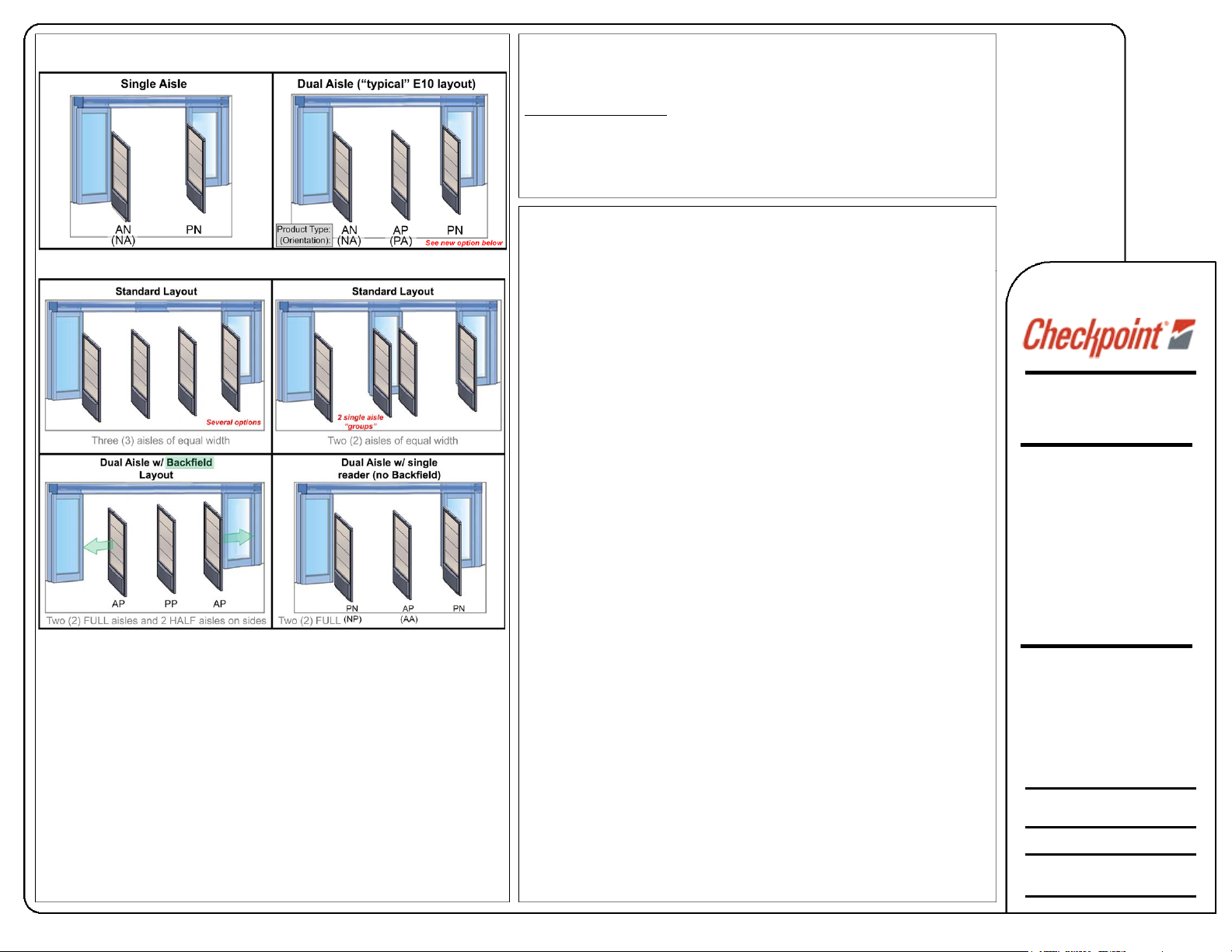
Floor Layout – Aisle Configurations
Several aisle configurations are possible. At least one antenna has to be
wired to the customer Ethernet port (assuming data service). During site
planning the recommend aisle layouts are determined.
Ref
er to the system Quick Start Guide (CKP P/N 10062884) for
additional details on the Supported Aisle Layouts.
Plenum Installation - Requirements
When installing the PSU in the soffit, there are special requirements if the space is
a plenum. Duct-work and also open areas, but only when used for HVAC ventilation,
are considered plenum spaces.
The G
lobTek PSU can be placed in the plenum but NOT higher than 3m [9ft 10in].
mounting in a plenum space, use proper plenum-rated wiring and an enclosure kit.
If
A licensed electrician must install per section 300.22 of the NEC.
Wa
rning: Any wiring in plenum areas must be plenum rated. Additionally, ensure that
the wire is installed in accordance with applicable
(local/national) electrical codes (for example, NEC 300.2 in the US).
e must be access to the power supply location.
Ther
Any deviation to these
specifications must be
approved by project
management. Contact your
local Checkpoint office.
Specifications for
EVOLVE Exclusive E10 2.0
Systems (all models)
Approved By:
CKP Engineering Services
Revision: *
Content: Aisle Layouts, Groups
and Plenum Installation
Page 3

Compliance
WRTZ-2000 TX/RX meets regional UHF broadcast rules:
FCC: UHF, 902 – 928 MHz / 4 Watt EIRP (US only)
ETSI: UHF, 865 – 868 MHz / 2 Watt ERP at 865.7 – 867.5 MHz
accordant to ETSI EN 302 208 version 1.3.1 (2009-07) (EU only)
Singapore: UHF, 920 – 925 MHZ/3.28 Watt EIRP, Modulation ASK,
7.4 MHz – 8.8 MHz/7.4 dBuA/m, Modulation None
Number 1 (shown at buttom left) shows the RFID Reader with 8 Coax ports.
It is possible for all of the system UHF Antennas to be used simultaneously, and
in this case, 8 total Coax Cables are connected to the reader. 4 cables will be
be routed to the “Active” pedestal’s 2 RFID Arrays (4 total patch antennas); and
at the opposite sides (on left and right of pedestal in center), the Arrays facing
this pedestal will be connected. This is shown in the figure below: where each of
2 readers is shown driving FULL left and right aisle. Specific settings have to be
applied to the RFID Reader to allow proper function
Evolve System - Peripheral Support
VisiPlus
•
• EVOLVE-Store (EV3 board)
Site Planning
Evaluate how antenna will be mounted: Concrete, Wood, or Tile finished
flooring. EAS and RFID power supplies should be planned based on the
configuration layout. If using peripherals such as VisiPlus or a DVR relay,
the trigger cable and 4C VisiPlus cables are routed from the SEC (if
necessary) to PRI (PSB) EAS reader.
Plan the distance to the door-frame, and whether or not specific antenna
types are required (see page 2 with options for some common layouts other "Mall opening" layouts are supported).
For the best alarm performance (reduced False Alarm counts), customer is
expected to maintain the Storefront layout so as to avoid high tag
concentrations directly in front of the system.
RFID Coax Cables and M-to-M Adapter connector for
some custom installations
RX Map:
Left Aisle (1) Right Aisle (0)
RX Map Settings RX Map Settings
RxMap 11 12 RxMap 01 34
RxMap 12 43 RxMap 02 21
RxMap 13 33 RxMap 03 33
RxMap 14 44 RxMap 04 44
Checkpoint Systems, Inc.
101 Wolf Drive
Thorofare, NJ 08086
1-800-257-5540
This drawing and the
accompanying written materials
are the exclusive property of
Checkpoint. Possession of this
document or any written
materials does not convey any
right to reproduce, disclose its
contents, or to produce, use or
sell anything it may describe.
Reproduction, disclosure or
use without specific prior
written authorization of
Checkpoint is strictly forbidden.
Any deviation to these
specifications must be
approved by project
management. Contact your
local Checkpoint office.
Specifications for
EVOLVE Exclusive E10 2.0
Systems (all models)
Approved By:
Engineering Services
Revision: *
Content: Compliance
 Loading...