

Page 1
NOTICE TO PERSONS RECEIVING THIS DRAWING
AND/OR TECHNICAL INFORMATION:
Title:
TUNING PROCEDURE
TR4022
Checkpoint Systems claims proprietary rights to the material disclosed hereon.
This draw in g and/or technical information is issued in confidence for engineering
information only and may not be reproduced or used to manufacture anything
shown or referred to hereon without direct written permission from Checkpoint
Systems to the user. This drawing and/or technical information is the property
of Checkpoint Systems and is loaned for mutual assistance, to be retur ned
when its purpose has been served.
THIS DRAWING AND/OR TECHNICAL INFORMATION IS THE
PROPERTY OF CHECKPOINT SYSTEMS, INC.
Revisions Revisions
Rev Description Date Engineer Rev Description Date Approved
01 ECN 03/28/2000 D. MERVA
USED ON
Doc Spec: Date:
Dwn: J. IANNUZZI Date: 03/29/2000
Chk: J. HUG Date: 03/29/2000
Eng: D. MERVA Date: 03/29/2000
Appd: E. ECKSTEIN Date: 03/29/2000
Size
A
Scale: N/A
Checkpoint Systems, Inc. 2000
Page
1
of
20
Page 2

TUNING PROCEDURE TR4022
TABLE OF CONTENTS
1.0 INTRODUCTION..........................................................................................................3
2.0 SYSTEM DESCRIPTION.............................................................................................3
3.0 SWITCH SETTINGS.....................................................................................................4
Switch 4 – Bin Elimination, Filters, Transmitter setting and Alarm Cycle Select.................................. 8
Switch 5 – System transmit address, Merchandise/Access Card Rejection............................................. 8
Switch 6 – Master/Slave configuration.................................................................................................... 9
Switch 7 – Sweep range select................................................................................................................. 9
4.0 LED DEFINITIONS.................................................................................................10
System Status Indicators........................................................................................................................10
Internal and external Sync and RF indicators – DS8, DS9, and DS10..................................................10
5.0 POTENTIOMETER ADJUSTMENT..........................................................................11
6.0 AUXILIARY CONNECTOR ......................................................................................12
7.0 SCREENS ....................................................................................................................13
8.0 TUNING.......................................................................................................................19
8.1 Master / Slave Setup.....................................................................................................19
8.2 Group Addressing (VERY IMPORTANT).................................................................................... 19
8.3 Slaving............................................................................................................................................ 19
____________________________________________________________________________________________________________________________
CHECKPOINT SYSTEMS, INC. CONFIDENTIAL AND PROPRIETARY INFORMATION, FOR INTERNAL USE ONLY.
Rev. 00 Page
2
Page 3

1.0 INTRODUCTION
This document describes the procedures required to properly tune a Strata System with the
TR4022 board. Many of the adjustments for the Strata are pre-tuned during the manufacturing
test process therefore adjustments required in the field have been minimized.
Adjustments such as center frequency and sweep are preset for 8.2 Mhz operation. If the system
is required to detect a different frequency tag the sweep range will need to be readjusted by the
installer.
Once properly configured, if poor performance results, the CSE should direct their efforts toward
finding the source of the interference in the environment. Several test signals are provided by the
TR4022 board, which may be viewed on an oscilloscope. These signals allow the CSE to identify
and measure ambient noise levels, resonances and other sources of environmental interference.
The DSP (digital signal processor) system automatically subtracts stationary resonances seen by
the antennas. The system offers flexibility to adjust for these circumstances. However, the
solution for environmental problems, is to determine the environmental problems and resolve
them. The options for adjusting to environmental problems are performed both in the analog and
digital realm by the technician. The analog solutions are reducing power on the transmit antennas
(2-loop and/or 3-loop), reduce the baseband gain, and adjust the sweep. In the digital toolbox
there are four user selectable filter parameters. These tools should be used only after the CSE has
attempted to correct the environment.
TUNING PROCEDURE TR4022
The Strata system is powered by a +24Vdc power supply, P/N 121878. This power supply can
power up to a maximum of three antennas.
2.0 SYSTEM DESCRIPTION
The Strata system is a transceiver design using both a 3-loop, 2-loop, and a 1-loop antenna design.
The Strata alternates between using the 2-loop antenna and the 3-loop antenna. The 1-loop
antenna is used as a shield that is tied to ground. This technique provides the system with
different views of the detection field allowing the system to improve detection by minimizing the
holes typically found at the crossbars of typical swept antennas.
During an antenna’s cycle, the system performs two “blasts” which are called a “bin”. There are
sixteen bins per frame. A bin consists of two “noise” cycles and two blast cycles, a blast is a
transmit cycle and then a receive cycle. During the noise cycle, the system is not transmitting,
only receiving ambient noise. This allows the system to establish the baseline noise level of the
environment for later comparison. The system then transmits or “pulses” the field and then
receives or “listens” for an echo of a tag signal. This frame is repeated on the other antenna. A tag
response need only be present on one of the antennas to cause an alarm. In effect the system
provides the best of both worlds, a 2-loop and 3-loop design.
____________________________________________________________________________________________________________________________
CHECKPOINT SYSTEMS, INC. CONFIDENTIAL AND PROPRIETARY INFORMATION, FOR INTERNAL USE ONLY.
Rev. 00 Page
3
Page 4

The switching between antenna loops minimizes the size of detection holes at the null points of
the RF field.
3.0 SWITCH SETTINGS
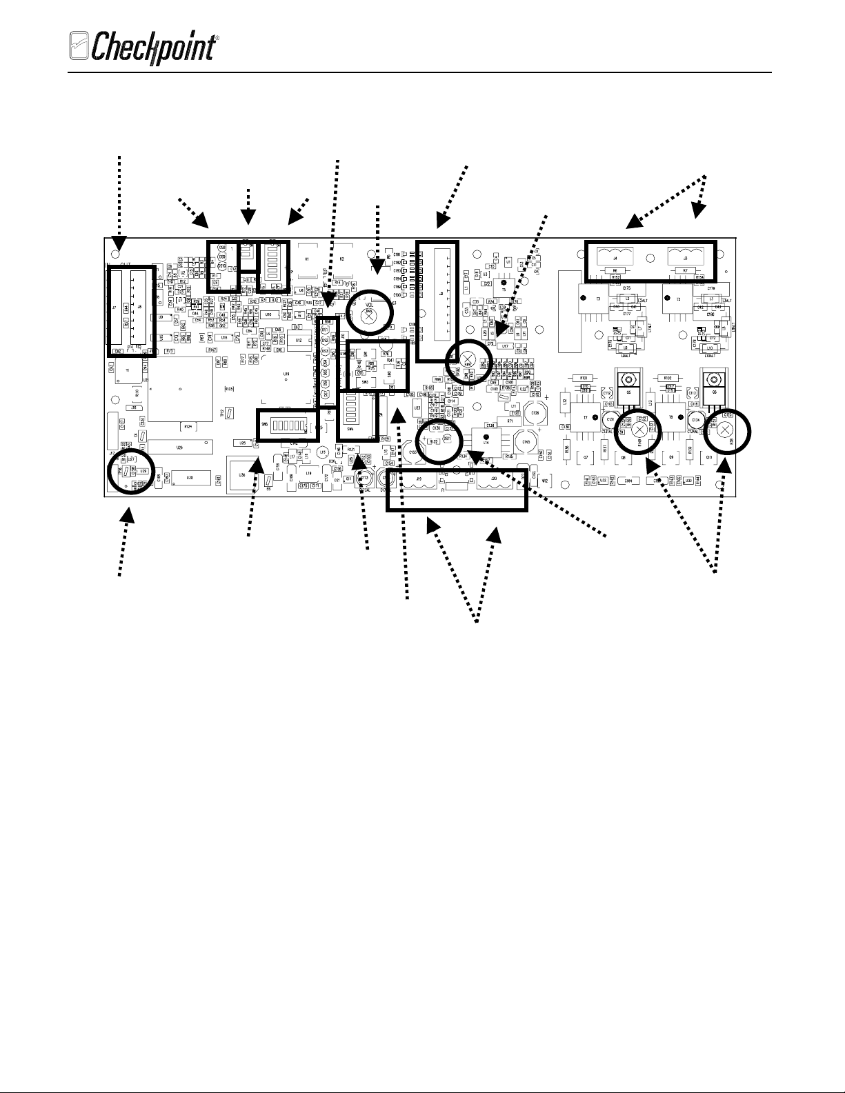
Table 1 explains each of the jumpers on the TR4022 board and 4.0 explains the switches on the
TR4022 board that must be configured before the system will operate. The illustrations on the
next pages shows the position of the jumpers, switches, and potentiometers on the TR4022 board
used during configuration. The top of the shield is held with 4 thumb turn screws. With the top of
the shield removed all the switches can be set without removing the electronics from the antenna.
If for some reason the circuit board needs to be removed from the antenna housing, remove the
three mounting screws from the backside of the board housing. Removing the rear cover of the
antenna assembly can access them. Before completely removing the electronics package from the
antenna loosen the screw near the TX1 and TX2 antenna connector and remove the spade lug.
MAKE SURE WHEN REINSTALLING THE ELECTRONICS PACKAGE THAT THE SPADE
LUG FROM THE SHORTED TURN IS REINSTALLED IN THE SAME PLACE.
TUNING PROCEDURE TR4022
____________________________________________________________________________________________________________________________
CHECKPOINT SYSTEMS, INC. CONFIDENTIAL AND PROPRIETARY INFORMATION, FOR INTERNAL USE ONLY.
Rev. 00 Page
4
Page 5
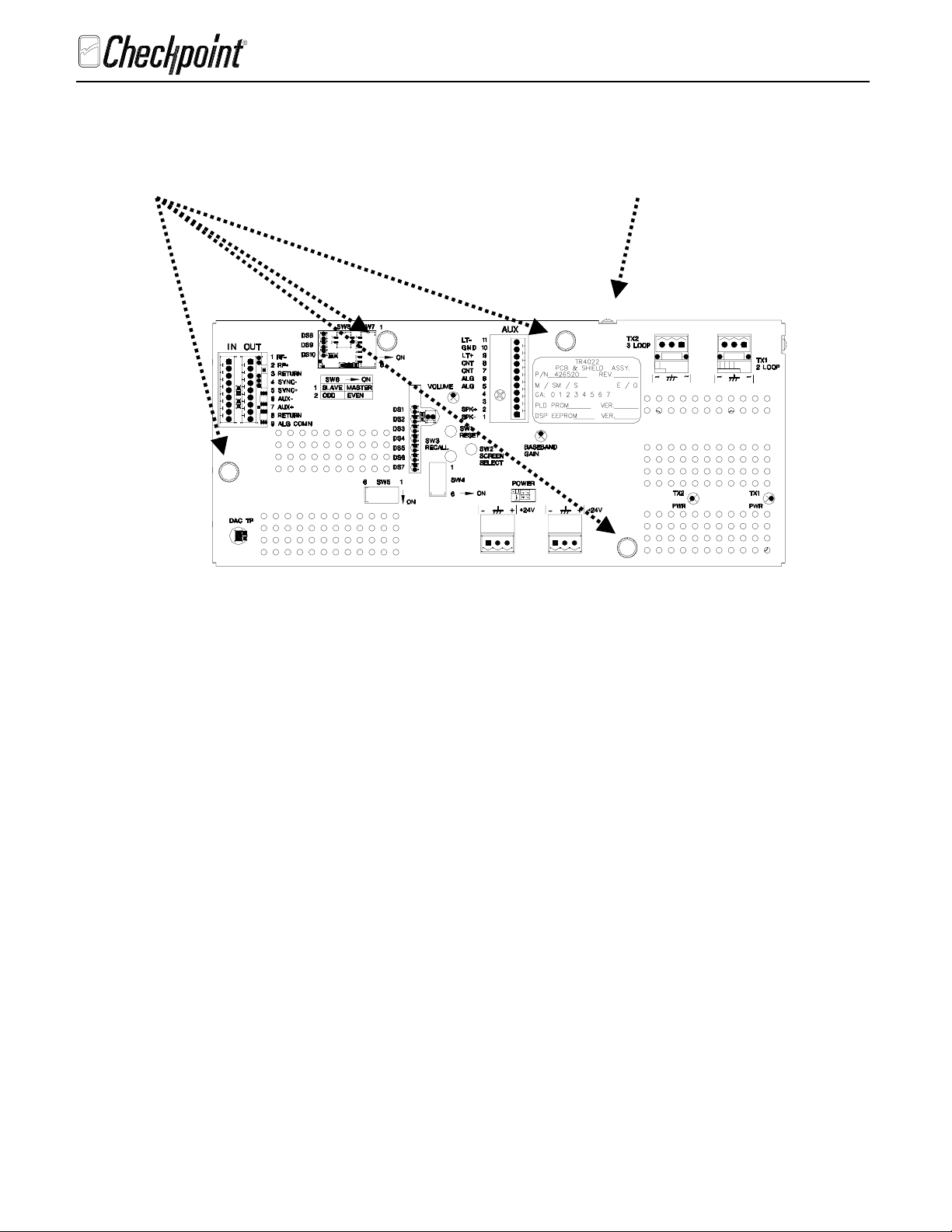
Thumb
screws for
top cover
TUNING PROCEDURE TR4022
Spade lug for
shorted turn
attaches here
____________________________________________________________________________________________________________________________
CHECKPOINT SYSTEMS, INC. CONFIDENTIAL AND PROPRIETARY INFORMATION, FOR INTERNAL USE ONLY.
Rev. 00 Page
5
Page 6
TUNING PROCEDURE TR4022
Slave In/Out
Connections
DS8 – DS10
SW6
DS1 –DS7
SW7
Sounder
Volume
Auxiliary
Connector
Antenna
Connections
R89
Baseband
Gain
DAC
TP16
SW 5 Group Address
& Q Selection
SW 4
SW 1,2,3
DS11 Power
TX1 & TX2
Power Adjust
+24 VDC
In/Out
____________________________________________________________________________________________________________________________
CHECKPOINT SYSTEMS, INC. CONFIDENTIAL AND PROPRIETARY INFORMATION, FOR INTERNAL USE ONLY.
Rev. 00 Page
6
Page 7

TUNING PROCEDURE TR4022
Table 1: Jumper Definitions
Jumper Label Function
J12 Alarm Group On: Will allow all the alarm group relays to
close when any pedestal within the group
alarms.
Off: Will not allow the alarm group signal to
pass to the next pedestal.
J16 (NO LABEL) Engineering Jumper.
The access panel must be removed to set all of the above jumpers
Table 2: Pushbutton Switch Definitions
Switch Function
SW-1 Reset software
SW-2 Screen select.
SW-3 Screen recall.
Depressing SW2 repeatedly will allow you to toggle from Screen 1 thru Screen 7. The second
pulse of the display found at the DAC test point TP16 identifies the screen being observed. See
Screen 1 on page 11.
Depressing and holding SW3 will cause the display at the DAC test point TP16 to show the
results of the last alarm for the screen being viewed.
____________________________________________________________________________________________________________________________
CHECKPOINT SYSTEMS, INC. CONFIDENTIAL AND PROPRIETARY INFORMATION, FOR INTERNAL USE ONLY.
Rev. 00 Page
7
Page 8

TUNING PROCEDURE TR4022
Switch 4 – Bin Elimination, Filters, Transmitter setting and Alarm Cycle
Select
Switch 4-1
Switch 4-2
Switch 4-3
Switch 4-4
Switch 4-5 OFF –
Switch 4-6 OFF -
OFF
OFF
Band Edge Bins
Eliminated
OFF
OFF
A FILTER
Software controlled transmitter
feature disabled
Short Alarm cycle
ON
OFF
High Band Bins
Eliminated
ON
OFF
B FILTER
OFF
ON
Low Band Bins
Eliminated
OFF
ON
C FILTER
ON -
Software controlled transmitter feature
enabled
ON –
Long alarm Cycle
ON
ON
Full Band Detect
No Bin Elimination
ON
ON
D FILTER
Switch 5 – System transmit address, Merchandise/Access Card Rejection
SW 5-3 SW 5-2 SW 5-1 Group
Addressing
OFF OFF OFF Address 0 Strata ‘98 Compatible (200hz, sweep down)
OFF OFF ON Address 1 100 Hz, jitter enabled, random sweep
OFF ON OFF Address 2 100 Hz, jitter enabled, random sweep
OFF ON ON Address 3 100 Hz, jitter enabled, random sweep
ON OFF OFF Address 4 100 Hz, jitter enabled, random sweep
ON OFF ON Address 5 100 Hz, jitter enabled, random sweep
ON ON OFF Address 6 100 Hz, jitter enabled, random sweep
ON ON ON Address 7 100 Hz, jitter disabled, linear sweep down
(Reserved, Engineering mode)
Systems that are ‘slaved’ together MUST have the group addressing switches set to the same
address. Conversely systems that are ‘unslaved’ but in close proximity must have unique
addresses. Address 0 is reserved for compatibility with older (Strata ’98) Strata systems and
should not be used in other installations. Address 7 is reserved for observing the analog input
signal.
SW 5-6 SW 5-5 SW 5-4 ‘Q’ Band
OFF OFF OFF All Tags - No M/A Rejection
OFF OFF ON 410/710 Tags (Merchandise Rejection)
OFF ON OFF 310/Access Card Rejection (Merchandise Rejection)
ON OFF OFF Hard Tags (Merchandise Rejection)
ON ON ON All Tags – (Merchandise Rejection)
____________________________________________________________________________________________________________________________
CHECKPOINT SYSTEMS, INC. CONFIDENTIAL AND PROPRIETARY INFORMATION, FOR INTERNAL USE ONLY.
Rev. 00 Page
8
Page 9

Switch 6 – Master/Slave configuration
ON OFF
Switch 6-1 Master (generates and
distributes RF and Sync)
The Master/Slave switch controls how the system will handle the sync and rf signals in
and out. A system MUST be in slave mode to use these input signals. In Master mode
these signals must be absent (refer to ‘Sync and RF indicators’ section).
ON OFF
Switch 6-2 ‘EVEN’ pedestal ‘ODD’ pedestal
The Even/Odd switch controls the transmit signal phase. This allows for a improved
received signal in the weaker carries. For rf slaved systems this switch is alternately set
even-odd-even-odd ….etc. For compatibility with older Strata systems ‘On’ is the same
as having the Even/Odd link installed.
Switch 7 – Sweep range select
TUNING PROCEDURE TR4022
Slave (system must receive
Sync signal)
The Strata 99-4022 board introduces the digital synthesis of the sweep frequencies from a DDS
chip. Without any test equipment the system can be setup without tuning for specific sweep
ranges.
SW 7-1 SW 7-2 Upper Band Edge
Off Off No shift
Off On Shift down 200 kHz
On Off No shift
On On Shift up 200 kHz
SW 7-3 SW 7-4 Lower Band Edge
Off Off No shift
Off On Shift down 200 kHz
On Off No shift
On On Shift up 200 kHz
SW 7-5 SW 7-6 Center Frequency Range Select Target
Off Off 8.2 MHz (nominal 7.6-8.7 MHz) 8.2 tags
Off On 8.6 MHz (nominal 7.8-9.4 MHz) 8.2 and 9.0 tags
On Off 9.0 MHz (nominal 8.5-9.5 MHz) 9.0 tags
On On 9.5 MHz (nominal 8.9-9.8MHz) 9.5 tags
____________________________________________________________________________________________________________________________
CHECKPOINT SYSTEMS, INC. CONFIDENTIAL AND PROPRIETARY INFORMATION, FOR INTERNAL USE ONLY.
Rev. 00 Page
9
Page 10

4.0 LED DEFINITIONS
System Status Indicators
DS1 – Inhibit Indicator
This LED indicates that a condition exists that would prevent normal detection of a tag,
typically excessive environmental noise. (At the end of an alarm cycle the inhibit LED
will light momentarily)
DS2 – Alarm
This LED indicates the system is alarming (useful for when the sounder and lights are
disconnected).
DS3 - Heartbeat
This LED indicates the system is operating normally. This LED blinks at an approximate
1 Hz rate. If the led is not blinking, it is a catastrophic failure and the board should be
replaced.
DS4 – Transmitter Status
This LED indicates the ‘power’ level of the transmitter, this led is normally on. When
the system detects an event above the alarm threshold it reduces the transmitter power
output and extinguishes the led.
DS5, DS 6 – Spare
(During development DS5 indicates the status of the external sync on power up)
(During development DS6 indicates the status of the external rf on power up)
DS7 – Q Disqualification Indicator
This LED indicates the system has detected a resonance however the ‘Q” of the resonance is
either above or below the limits selected by the ‘Q’ qualification switches.
TUNING PROCEDURE TR4022
Internal and external Sync and RF indicators – DS8, DS9, and DS10
On power up or reset the system ‘reads’ the sync, rf, and switch status and configures the
board appropriately. The configuration algorithm is as follows.
M/S
Switch
(SW 6-1)
Master Absent Absent OK – self generating sync and RF
Master Absent Present ERROR Off Blink Off
Master Present Absent ERROR Blink Off Off
Master Present Present ERROR Off Off Blink
Slave Absent Absent ERROR Blink Blink Blink
Slave Absent Present OK – External sync and Self
Slave Present Absent ERROR Blink Blink Blink
Slave Present Present OK – External sync and External
____________________________________________________________________________________________________________________________
CHECKPOINT SYSTEMS, INC. CONFIDENTIAL AND PROPRIETARY INFORMATION, FOR INTERNAL USE ONLY.
External
RF
Source
External
Sync Source
Condition DS10
(Master)
Green
On Off Off
(system is a master)
Off On Off
generating RF (system is a submaster)
Off Off On
RF (system is a slave)
Rev. 00 Page
(Sub-master)
DS9
yellow
DS8
(Slave)
Red
10
Page 11

The system will not operate in any of the above ‘ERROR’ conditions. If an error
condition is indicated the transmitter will be shut down and the system will not ‘pass through’ the
sync pulse.
5.0 POTENTIOMETER ADJUSTMENT
The table below provides all of the adjustment pots on the TR4022 board along with their
function and how to adjust each pot. The factory should set all of these pots and field adjustment
should not be necessary.
Table 6: Definition of Adjustment Potentiometers
Label Function Proper Adjustment
TUNING PROCEDURE TR4022
TX1 PWR (R38) 2-loop Antenna Power
(TX1)
TX2 PWR (R149) 3-loop Antenna Power
(TX2)
BASEBAND GAIN
(R89)
VOLUME (R46) Sonalert Volume Adjust to desired level (CW-increases volume)
Baseband Gain Usually set fully CW (maximum gain) Adjust for a maximum of
DO NOT ADJUST HIGHER, SET BY FACTORY
(to decrease power turn R38 clockwise)
DO NOT ADJUST HIGHER, SET BY FACTORY
(to decrease power turn R149 clockwise)
1.5V on screen 1
____________________________________________________________________________________________________________________________
CHECKPOINT SYSTEMS, INC. CONFIDENTIAL AND PROPRIETARY INFORMATION, FOR INTERNAL USE ONLY.
Rev. 00 Page
11
Page 12

TUNING PROCEDURE TR4022
6.0 AUXILIARY CONNECTOR
LABEL PIN NUMBER FUNCTION
LT- 11 11 Negative of lights
GND 10 10 Board ground (be very careful what is connected to this pin, so as not to create
ground loops)
LT+ 9 9 Positive of lights
CNT 8 * 8 Relay normally open contact (closure upon alarm, same duration as lights)
CNT 7 * 7 Relay common contact
ALG 6 * 6 Relay normally open contact (triggered by alarm group, momentary closure)
ALG 5 * 5 Relay common contact
SPK+ 2 2 Positive of speaker
SPK- 1 1 Negative of speaker
____________________________________________________________________________________________________________________________
CHECKPOINT SYSTEMS, INC. CONFIDENTIAL AND PROPRIETARY INFORMATION, FOR INTERNAL USE ONLY.
Rev. 00 Page
12
Page 13

7.0 SCREENS
Transmitter power
Bin 11
TUNING PROCEDURE TR4022
Screen 1
2 Loop
Screen 1
2 Loop Threshold
3 Loop Threshold
2 Loop
“ANALOG SCREEN”
Frame Field Current Activity
Display Area Display Area
3 Loop
____________________________________________________________________________________________________________________________
CHECKPOINT SYSTEMS, INC. CONFIDENTIAL AND PROPRIETARY INFORMATION, FOR INTERNAL USE ONLY.
Rev. 00 Page
13
Page 14

7.1 Frame Field Display Area
The first two horizontal divisions of ALL screen displays contains the following
information:
(each vertical division has a value of 2 units)
Pulse 1 – Scope Trigger
Pulse 2 – Screen currently displayed (Previous page shows screen 1 being displayed)
Pulse 3 – Bin Number (Displays in which Bin the last alarm occurred)
Pulse 4 – Antenna (2 loop or 3 loop)
Pulse 5 – Transmitter Power Output (pulse at top of screen shows transmitter at full
Power)
TUNING PROCEDURE TR4022
The remaining display is the
Current Activity Display Area
for that screen.
____________________________________________________________________________________________________________________________
CHECKPOINT SYSTEMS, INC. CONFIDENTIAL AND PROPRIETARY INFORMATION, FOR INTERNAL USE ONLY.
Rev. 00 Page
14
Page 15

Screen 2
TUNING PROCEDURE TR4022
Screen 2
Screen 3
Similar to early Strata DA C output for the 2 loop
Screen 3
Similar to early Strata DA C output for the 3 loop
____________________________________________________________________________________________________________________________
CHECKPOINT SYSTEMS, INC. CONFIDENTIAL AND PROPRIETARY INFORMATION, FOR INTERNAL USE ONLY.
Rev. 00 Page
15
Page 16

TUNING PROCEDURE TR4022
Blast 1 ArtifactPlateau
Blast 2 ArtifactPlateau
Blast 1 Sample to Sample Signal Plateau
Blast 1 Sample to Sample Noise Plateau
Blast 2 Sample to Sample Signal Plateau
Blast 2 Sample to Sample Noise Plateau
Blast 1 Bin to Bin Signal Plateau
Blast 1 Bin to BinNoise Plateau
Blast 2 Bin to Bin Signal Plateau
Blast 2 Bin to BinNoise Plateau
Blast 1 AlarmPlateau
Blast 2 AlarmPlateau
Blast 1 & Blast 2 Alarm Thresholds (1 & 2 Locked)
SCREEN 2 AND SCREEN 3 (DETAILED FORMAT)
Screen 2 and Screen 3 have similar formats providing further detail on their respective
2 Loop and 3 Loop DAC signals. Using Screen 2 as an example, the individual 2 Loop DAC
signals are detailed below. The same format would apply for the 3 Loop DAC signals found on
Screen 3.
____________________________________________________________________________________________________________________________
CHECKPOINT SYSTEMS, INC. CONFIDENTIAL AND PROPRIETARY INFORMATION, FOR INTERNAL USE ONLY.
Rev. 00 Page
16
Page 17

Screen 4
TUNING PROCEDURE TR4022
Screen 4 (Engineering Use)
“Q” of last alarm event
Screen 5
“Q” Shape of last event
Screen 5 (Engineering Use)
Live “Q” Qualification Display
____________________________________________________________________________________________________________________________
CHECKPOINT SYSTEMS, INC. CONFIDENTIAL AND PROPRIETARY INFORMATION, FOR INTERNAL USE ONLY.
Rev. 00 Page
17
Page 18

3 Loop Threshold
2 Loop Threshold
Screen 6
TUNING PROCEDURE TR4022
Screen 6
2 Loop
Bin to Bin
3 Loop
Bin to Bin
____________________________________________________________________________________________________________________________
CHECKPOINT SYSTEMS, INC. CONFIDENTIAL AND PROPRIETARY INFORMATION, FOR INTERNAL USE ONLY.
Rev. 00 Page
18
Page 19

Screen 7
TUNING PROCEDURE TR4022
Screen 7
8.0 TUNING
8.1 Master / Slave Setup
The first step in the process for tuning a Strata pedestal with the TR4022 board is to
configure SW 6-1 according to how the pedestal is used in conjunction with other
pedestals. Configure either as a Master (ON) , or Slave (OFF). See Switch 6 –
Master/Slave configuration
8.2 Group Addressing (VERY IMPORTANT)
If the pedestal is working as part of a group of pedestals and connected together by the
interpedestal cable, set the group address at SW5-1, 2, 3 the same for all the pedestals in
the group. See Table 4. If a pedestal or group of pedestals is installed within 40’ of one
another then they may have to be slaved. When slaving is required the group address for
all the pedestals must be set the same.
8.3 Slaving
Slaving can be accomplished by attaching a two wire shielded cable with a drain wire to
the OUT connector J8 terminals 4 & 5 (drain wire to terminal 3) on the last pedestal in the
group to the IN connector J7 terminals 4 & 5 (drain wire to terminal 3) on the first
pedestal of the next group. NOTE: Polarity of the wires is important.
Alarm Counter Display
(above shows
29)
____________________________________________________________________________________________________________________________
CHECKPOINT SYSTEMS, INC. CONFIDENTIAL AND PROPRIETARY INFORMATION, FOR INTERNAL USE ONLY.
Rev. 00 Page
19
Page 20

TUNING PROCEDURE TR4022
Apply 24 VDC power and check that DS11 is illuminated. DS3 should also be flashing
intermittently.
The transmitter output is preset at the factory and should not require adjustment.
Adjust the baseband gain potentiometer R89 for a noise level of less than 1.5V at Screen
1. This can be viewed by attaching an oscilloscope to the DAC test point TP16 and
selecting Screen 1 by depressing SW2. Scope setting: 1V/DIV; 200uS/DIV.
While viewing Screen 1 check the sweep setting of the transmitter for the frequency of the
tags being used. Standard retail systems are set to sweep from 7.6 – 8.7 Mhz. Using a
Grid Dip Meter placed flat on the floor approximately 1.5 to 2 feet from the antenna check
the sweep range by varying the frequency dial on the meter. The following illustrations
will give you an idea of what the induced signal from the Dip Meter will look like at
Screen 1.
8.7 Mhz 8.2 Mhz 7.6 Mhz
Set the detection parameters at SW4-3 & 4 to OFF/OFF. This is the same as the ‘C’ filter
on earlier Strata. If more filtering is required because of environmental influences see
Table 3.
Set SW5-4, 5, 6 for the type of tags being used. See Table 4. All OFF has no ‘Q’
qualification and thereby will not defeat alarms caused by merchandise.
Set the volume of the Sonalert by adjusting potentiometer R46.
No other adjustments are required. Test the system with several of the customers’ tags to
insure that the system is detecting properly. The sensitivity of the system may vary due to
environmental influences and the selection of the filtering set by SW4-3 & 4.
____________________________________________________________________________________________________________________________
CHECKPOINT SYSTEMS, INC. CONFIDENTIAL AND PROPRIETARY INFORMATION, FOR INTERNAL USE ONLY.
Rev. 00 Page
20
 Loading...