

Page 1
Performa Mullion Mount (AC-125M)
RFID Proximity Reader
Background
The following will discuss Performa Mullion Mount Proximity Reader as they are intended to install on an
Access Control System by Checkpoint Systems, Inc. This reader is available in two colors; Gray (Model #
AC-125MG - Part# 304627) and Off-White (Model# AC-125MW - Part # 140058).
Specifications
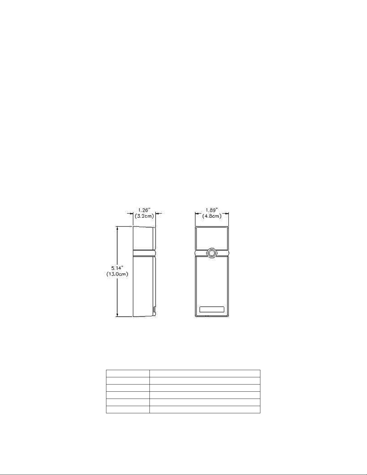
The Mullion Mount proximity reader is suitable to mount on metal, such as door mullions, with no impact
on performance. This device is designed to use the 26-Bit Weigand data format and is targeted to operate
at 12VDC @ 150mA, but is capable of operating between 10.8VDC and 14.8VDC. For these readers to
perform properly, the installation must use Belden 5304FE or equivalent wire.
This proximity reader has a read range of up to 4” using the Performa Proximity Plus Cards from
Checkpoint. The reader will transmit a frequency of 13.56MHz and will operate between –22°F and
150°F. The Performa reader carries the FCC Part 15USA certification.
Performa Mullion Mount Reader Dimensions
The following is a drawing of the outer dimensions of this proximity reader.
Wiring
The Performa readers come with six wires, but currently only five wires will be used. As mentioned above
this reader is a Weigand device and uses the 26-Bit Weigand format. The wire specification is Belden
5304FE or equivalent. The wire is 18 gauge, six conductors, stranded, and shielded. With this wire the
reader can mount up to 500’ from the controller, as stated within the Weigand specification. The standard
co lo r-co ding ha s be en us e d :
Black
Red
White
Green
Brown
Blue
Comm on
Power for Reader (12VDC)
Data 1
Data 0
LED Control
Beeper Control
(Not Used At This Time)
Page 2
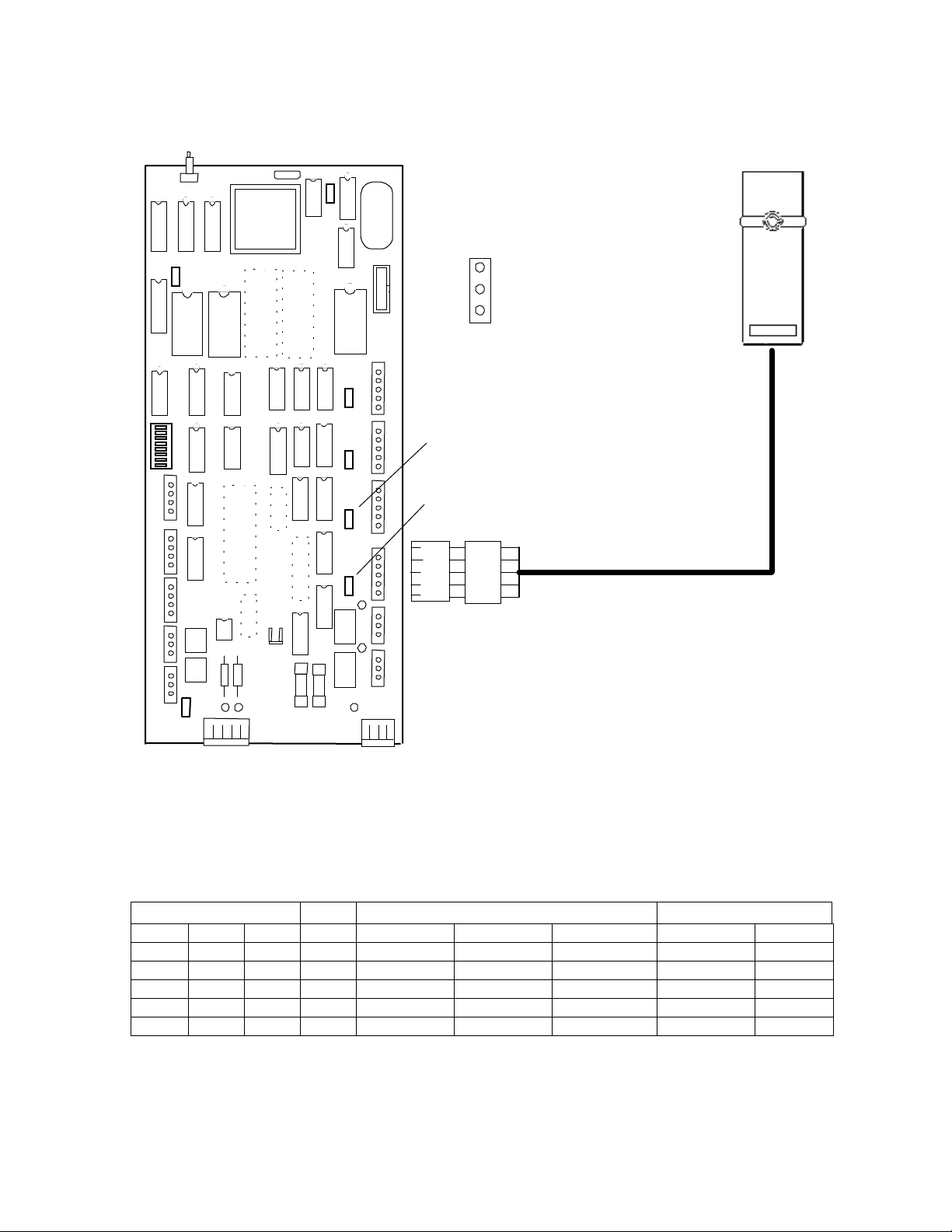
The following is a diagram of wiring the Performa reader to a Checkpoint Terminal Controller:
Battery
Jum per 7 and 8 Numbering
12v
5v
JM P 8
R eader 1
Voltage
JM P 7
R eader 2
Voltage
LED
"0"
"1"
5V
GND
Brown
Green
White
Red
Black
3 (top)
2 (cent er )
1 (bot tom )
Note: Please refer to your
hardware for use of the
beeper control and the
sixth wire. Checkpoint
does not land the beeper
con t ro l wire to its own
board.
Dip Switch Settings
LED and beeper features are controlled by a dip switch pack located on the back of the reader. The first
three positions of the dip switch pack is all that is needed to change the output of the LED and beeper. The
fourth dip switch is reserved for future use. The following chart shows the dip switch setting and
functionality of the LED and beeper. The LED is bi-color and can provide Red, Green, and Amber states.
The beeper is a standard piezo or magnetic beeper.
Switches Note LED Beeper
SW 1 SW 2 SW 3 Ready Denied Admit Denied Admit
ON ON ON GREEN
R/G FLASH
RED 3s 3 SHORT NONE
ON ON OFF RED R/G FLASH GREEN 3s 3 SHORT NONE
ON OFF OFF RED R/G FLASH
NO CHANGE
3 SHORT 1 LONG
OFF ON ON RED R/G FLASH GREEN 3s 3 SHORT 1 LONG
OFF OFF OFF 1 RED
FLICKERS FLICKERS
CHIRPS CHIRPS
Notes:
1. This is a test mode for the reader. This strictly tests the reader itself and indicates no functionality of
the Terminal Controller.
 Loading...