

Page 1

Evolve F10
Installation Manual
Document Version *60
P/N 10034505
Page 2

EVOLVE F10 Installation Manual
Rev
Description
Date
Authors
00
Preliminary Release
11/29/2012
Ron Decker , Joseph Galanti,
Copyright © 2012 by Checkpoint Systems Inc.
Released 11/29/2012.
Published by:
Checkpoint Systems Inc.
101 Wolf Drive
Thorofare, NJ 08086
For use with the Checkpoint EVOLVE F10 Systems.
Trademarks
Checkpoint is a registered trademark of Checkpoint Systems, Inc.
Checkpoint, Liberty, Evolve, and VisiPlus are registered trademarks of Checkpoint Systems, Inc.
All rights reserved. Info rmation in this document is subject to change without notice.
Other products are © or ® of their respective manufacturers or copyright holders.
Companies, names and data used in examples herein are fictitious unless otherwise noted. No part
of the contents of this book may be reproduced or transmitted in any form or by any means
without the written permission of the publisher.
Copyright and Warranty Information
All rights reserved. T he information in this document is subject t o change without notice.
Because of the changing nature of this product information presented in the F10 Installation
Manual, Checkpoint Systems, I nc. is not lia ble for any omissions, misstatements, o r other errors of
information.
The information presented in this document may not be copied, used or disclosed to others for the
purpose of procurement or manufacturing without the written permission of Checkpoint Systems,
Inc. This gu i de and the pro ducts discussed in this guide are the exclus ive property of Checkpoint
Systems Inc. Copyright laws of the U nited States protect all information and products.
Copyright© 2012 Checkpoint Systems, Inc. All rights reserved.
Document Revision Information
Part Number: 10034505
EVOLVE F10 Installation Manual, version 00
Greg Plizak
F10 Installation Manual Rev.*60 2 of 71
Page 3

Statements
• The device(s) may only be used for the intended purpose designed by for the manufacturer.
• Unauthoriz ed changes and the use of spa re parts and additional devi ces which have not been sold or
recommended by the manufacturer may cause fire, electric shocks or injuries. Such unauthorized measures
shall exclude any liability by the manufacturer.
• The liability-prescriptions of the manufacturer in the issue valid at the time of purchase are valid for the
device. The manufacturer shall not be held legally responsible for inaccuracies, errors, or omissions in the
manual or automatically set parameters for a device or for an incorrect application of a device.
• Repairs may only be executed by the manufacturer.
• Installation, operation, and maintenance procedures should only be carried out by qualified personnel.
• Use of the device and its installation must be in accordance with national legal requirements and local
electrical codes.
• When worki ng on devices the valid safety regulations must be observed.
• Before touching the device, the power supply must always be interrupted. Make sure that the device is
without volt age by measuring. The fading of an oper ation control (LED) is not an indicator for an
interrupted power supply or the device being out of voltage!
• The installer or licensed electric ia n must follow all NEC and local codes.
• All wires routed in the floor per article 725 must be Class 2 and be UL Listed. UL Recognized AWM may
be employed, provided it is enclosed in Conduit or ENT.
• The F10 is not to be installed in Wet Locations. For indoor use only.
• Checkpoint is not responsible for or warrant any repairs or rework to the flooring during or after the
installation of the antenna.
Guide Conventions
Document conventions are described below:
This is a Warning icon. When it ap pears, it indicates a potentially hazardous situation, which if not
avoided, could result in d eath or serious injury.
Caution: This is a Caution icon. W hen it ap pears, it indicates a potentially hazar d o us sit ua ti on which
if not avoided, could result in property damage or malfunction of equipment.
Note: This is a Tip icon. When it appears, the corresponding text indicates a helpf ul note or tip when
using the feature.
For all measurements:
• To meet both CE and FCC requirements, all measurements will be listed in the following for mat:
Metric [Imperial], for example: 46cm [18in] or 0.9m [3ft].
• Where non-S.I. units are applicable, such as 6’ x 4’ or 3/16”, the format in this case is Unit
(metric).
Where on-screen computer instructions are given:
Button Name - This describes a button or an on-screen command or drop-down selection.
For example, the <DONE> button is represented in this document as Done.
Key Name - This describes a keystroke on a keyboard. For example, Ctrl represents the control key.
F10 Installation Manual Rev. *60 3 of 71
Page 4

Important Information to our Users in North America
FCC Regulatory Compliance Statement
Checkpoint Systems, Inc., offers Electronic Article Surveillance (EAS) or Radio Frequency
Identification Products that have been FCC certified or verified to 47 CFR Part 15 Subparts B/C.
Appropriately, one of the following labels will apply to the approval:
NOTE: This equipment has been tested and found to comply with the limits for a class A digital
device, pursuant to Part 15 of the FCC Rules. These limits are designed to provide reasonable
protection against harmful interference when the equipment is operated in a commercial
environment. This equipment generates, uses, and can radiate interference to radio
communications. Operation of this equipment in a residential area is likely to cause harmful
interference in wh ich c as e t he u ser w il l b e r equ ire d to corre ct t he i nt er fer en ce at hi s o wn expense.
- OR -
This device complies with Part 15 of the FCC Rules. Operation is subject to the following
two conditions: (1) including this device may not cause harmful interference, and (2) this
device must accept any interference received, including interference that may cause
undesired operation, which may include intermittent decreases in detection and/or
intermittent increases in alarm activity.
Industry Canada Regulatory Compliance Statement
Under Industry Canada regulations, this radio transmitter may only operate using an antenna of a
type and maximum (or lesser) gain approved for the transmitter by Industry Canada. To reduce
potential radio interference to other users, the antenna type and its gain should be so chosen that
the equivalent isotropically radiated power (e.i.r.p.) is not more than that necessary for successful
communication.
This radio transmitter (IC: 3356B-F20) has been approved by Industry Canada to operate with
the antenna types listed below with the maximum permissible gain and required antenna
impedance for each antenna type indicated. Antenna types not included in this list, having a gain
greater than the maximum gain indicated for that type, are strictly prohibited for use with this
device.
Operation is subject to the following two conditions:
(1) this device may not cause interference, and
(2) this device must accept any interference, including interference that may cause undesired
operation of the device.
To reduce potential radio interference to other users, the antenna type and its gain should be so
chosen that the equivalent isotropically radiated power (e.i.r.p.) is not more than that permitted
for successful communication.
F10 Installation Manual Rev. *60 4 of 71
Page 5

Industrie Canada
Conformément à la réglementation d'Industrie Canada, le présent émetteur radio peut fonctionner
avec une antenne d'un type et d'un gain maximal (ou inférieur) approuvé pour l'émetteur par
Industrie Canada. Dans le but de réduire les risques de brouillage radioélectrique à l'intention des
autres utilisateurs, il faut choisir le type d'antenne et son gain de sorte que la puissance isotrope
rayonnée équivalente (p.i.r.e.) ne dépasse pas l'intensité nécessaire à l'établissement d'une
communication satisfaisante.
Le présent émetteur radio (IC: 3356B-F20) a été approuvé par Industrie Canada pour fonctionner
avec les types d'antenne énumérés ci-dessous et ayant un gain admissible maximal et l'impédance
requise pour chaque type d'antenne. Les types d'antenne non inclus dans cette liste, ou dont le
gain est supérieur au gain maximal indiqué, sont strictement interdits pour l'exploitation de
l'émetteur.
Le fonctionnement de l’ appareil est soumis aux deux conditions suivantes:
(1) Cet appareil ne doit pas perturber les communications radio, et
(2) cet appareil doit supporter toute perturbation, y compris les perturbations qui pourraient
provoquer son dysfonctionnement.
Pour réduire le risque d'interférence aux autres utilisateurs, le type d'antenne et son gain
doivent être choisis de façon que la puissance isotrope rayonnée équivalente (PIRE) ne
dépasse pas celle nécessaire pour une communication réussie.
Equipment Safety Compliance Statement
Checkpoint Systems’ EAS or Radio Frequency Identification products have been designed to be
safe during normal use and, where applicable, certain components of the system or accessory
sub-assemblies have been certified, listed or recognized in accordance with one or more of the
following Safety standards: UL 1012, UL 1037, UL 1310, UL 60950-1, CSA C22.2 No. 205,
CSA C22.2 No. 220, CSA C22.2 No. 223, CSA C22.2 No. 60950-1. Additional approvals may
be pending.
WARNING: Changes or modifications to Checkpoint’s EAS or Radio Frequency Identification
(RFID) equipment not expressly approved by the party responsible for assuring compliance
could void the user’s authority to operate the equipment in a safe or otherwise regulatory
compliant manner.
F10 Installation Manual Rev. *60 5 of 71
Page 6

Important Information to our Users in Europe
CE Regulatory Compliance Statement
Where applicable, Checkpoint Systems, Inc. offers certain Electronic Article Surveillance (EAS)
products that have CE Declarations of Conformity according to R&TTE Directive 99/5/EC,
EMC Directive 2004/108/EC, and Low Voltage Directive 2006/95/EC.
System Electromagnetic Compatibility (EMC) has been tested and notified through Spectrum
Management Authorities if necessary, using accredited laboratories, whereby, conformity is
declared by voluntarily accepted European Telecommunications Standards Institute (ETSI)
standards EN 301489-1 and EN 300330-2.
NOTE: Certain Electronic Article Surveillance (EAS) equipment have been tested and found to
conform with the CE emission and immunity requirement in Europe. This equipment generates,
uses, and can radiate radio frequency energy and, if not installed and used in accordance with the
instruction manual, may cause harmful interference to radio communications. Under unusual
circumstances, interference from external sources may degrade the system performance, which
may include intermittent decreases in detection and/or intermittent increases in alarm activity.
However, there is no guarantee that interference will not occur in a particular installation. If this
equipment experiences frequent interference from external sources or does cause harmful
interference to radio communications reception, which can be determined by turning the
equipment off and on, please contact a Checkpoint Systems representative for further assistance.
Equipment Safety Compliance Statement
Checkpoint Systems Electronic Article Surveillance products have been designed to be safe
during normal use and, where applicable, certain components of the system or accessory subassemblies have been declared safe according to the European Low Voltage Directive (LVD) by
being certified, listed, or recognized in accordance with one or more of the following European
safety standards; EN 60950-1, EN 50364, EN 60742.
WARNING: Changes or modifications to Electronic Article Surveillance equipment not
expressly approved by the party responsible for assuring compliance could void the user’s
authority to operate the equipment in a safe or otherwise regulatory compliant manner additional
approvals may be pending.
F10 Installation Manual Rev. *60 6 of 71
Page 7

Table of Contents
TATEMENTS ............................................................................................................................................................. 3
S
GUIDE CONVENTIONS ................................................................................................................................................ 3
CHAPTER 1: INTRODUCTION ................................................................................................................................... 9
BACKGROUND ........................................................................................................................................................... 9
Overview ............................................................................................................................................................ 10
F10 SYSTEM HARDWARE......................................................................................................................................... 10
SYSTEM DIAGRAMS ................................................................................................................................................. 11
GROUPING MULTIPLE ANTENNAS ............................................................................................................................ 12
2 X 1 METER CONFIGURATION ................................................................................................................................. 12
CHAPTER 2: SITE SURV EY ....................................................................................................................................... 13
Overview ............................................................................................................................................................ 13
ANTENNA DISTANCE FROM INTERFERING ELEMENTS .............................................................................................. 13
SYSTEM PERFORMANCE CONSIDERATIONS .............................................................................................................. 14
DETERMINING THE ELECTRONICS LOCATION .......................................................................................................... 14
ENVIRONMENTAL CONSIDERATIONS ....................................................................................................................... 15
SITE SURVEY CONCLUSION ..................................................................................................................................... 15
CHAPTER 3: PHYSICAL INSTALLATION ............................................................................................................. 16
Chapter Outline.................................................................................................................................................. 16
REQUIREMENTS ....................................................................................................................................................... 16
Tools ................................................................................................................................................................... 16
Parts ................................................................................................................................................................... 17
INSTALLATION OUTLINE .......................................................................................................................................... 17
Antenna Installation ........................................................................................................................................... 17
F10, 1 METER AND 2 METER FLOOR CUTS .............................................................................................................. 18
Floor Cut Depth ................................................................................................................................................. 19
COMMON WIDER FLOOR CUTS ................................................................................................................................ 20
MOUNTING THE ELECTRONICS ENCLOSURE ............................................................................................................ 21
MOUNTING THE POWER SUPPLY .............................................................................................................................. 23
GS-599ES(R) Installation................................................................................................................................... 23
GS-599MC-KIT(R) Installation ......................................................................................................................... 23
FINISHING INSTALLATION ........................................................................................................................................ 24
CHAPTER 4: WIRING ................................................................................................................................................. 25
Overview ............................................................................................................................................................ 25
ANTENNA WIRING ................................................................................................................................................... 26
Wiring Components ............................................................................................................................................ 26
Placement ........................................................................................................................................................... 26
Wiring the F10, 2 Meter System ......................................................................................................................... 27
Wiring the F10, 1 Meter System ......................................................................................................................... 31
Adjusting Jumper Settings .................................................................................................................................. 32
WIRING THE 2 X 1 METER SYSTEM .......................................................................................................................... 32
OVERVIEW ............................................................................................................................................................... 33
Coax Cable / A1116 Wiring ............................................................................................................................... 33
Remote Voice Alarm ........................................................................................................................................... 34
Alarm Post Wiring ............................................................................................................................................. 35
24VDC Power Supply Wiring ............................................................................................................................ 36
WIRING BETWEEN F10 SYSTEMS FOR SYNC ............................................................................................................ 37
Sync Cable and Power Supply Wiring ............................................................................................................... 37
WIRING PERIPHERALS .............................................................................................................................................. 38
F10 Installation Manual Rev.*60 7 of 71
Page 8

CHAPTER 5: F10 SYSTEM CONFIGURATION VIA DM S .................................................................................... 39
Overview ............................................................................................................................................................ 39
SYSTEM SETUP USING DMS .................................................................................................................................... 39
Single-Electronic System Setup .......................................................................................................................... 39
Multi-Electronic Systems (Sync Configuration) ................................................................................................. 44
APPLICATION-BASED DETECTION MODES ............................................................................................................... 44
Standard: 8.2 and Library: 9.5
Corral: 8.2, 9.0
....................................................................................................................................................... 45
Reverse Corral: 8.2, 9.0
Apparel: 8.2, 9.2
Pharma: 8.2, 7.2
RazorKeeper: 8.2, 7.2
Immunity: 8.2
..................................................................................................................................................... 45
..................................................................................................................................................... 45
.............................................................................................................................................. 45
......................................................................................................................................................... 45
Japan I: 8.2=9.5 and Japan II: 8.2, 9.5
............................................................................................................................... 45
........................................................................................................................................... 45
................................................................................................................... 46
ALARM SEVERITY .................................................................................................................................................... 46
CONFIGURING SAM (SMART ALARM MANAGEMENT) ............................................................................................ 47
Navigating to the SAM Screen ........................................................................................................................... 47
Changing the Patterns ....................................................................................................................................... 50
Changing the Matrix .......................................................................................................................................... 52
U
PDATING THE SYSTEM
CHAPTER 6: TUNING PROCEDURES (1M AND 2M VARY) .............................................................................. 53
.............................................................................................................................................. 52
Overview ............................................................................................................................................................ 53
TR4215 FEATURES .................................................................................................................................................. 53
BASIC TUNING METHODS USING DMS.................................................................................................................... 53
NOISE SOURCES ....................................................................................................................................................... 54
ANALOG VIEW ......................................................................................................................................................... 55
Typical Tuning Procedure.................................................................................................................................. 55
EVALUATE JUMPER POSITIONS ................................................................................................................................ 56
System Specific Procedures ................................................................................................................................ 56
For 2 Meter System ............................................................................................................................................ 56
For single 1 Meter or 2 x 1 Meter System .......................................................................................................... 56
CONFIGURING THE SYSTEM FOR ASYNCHRONOUS NOISE ........................................................................................ 57
RESONANCE SOURCES ............................................................................................................................................. 59
Remedying Resonances ...................................................................................................................................... 59
Jammer Indication ............................................................................................................................................. 61
DATA RETRIEVAL .................................................................................................................................................... 61
Event History ..................................................................................................................................................... 61
Snap Shot feature ............................................................................................................................................... 61
APPENDIX A: POWER SUPPLY ................................................................................................................................ 62
POWER SUPPLY DETAILS ......................................................................................................................................... 62
Power Supply Used in United States, Canada and Europe ................................................................................ 62
Power Supply Used in Australia ........................................................................................................................ 64
APPENDIX B: PARTS LISTS ...................................................................................................................................... 65
F10 PARTS LIST ....................................................................................................................................................... 65
APPENDIX C: INTERACTIONS ................................................................................................................................. 66
F10 SYSTEM – PROXIMITY TO DEACTIVATION UNITS .............................................................................................. 66
F10 SYSTEM – PROXIMITY TO OTHER SYSTEMS ...................................................................................................... 67
APPENDIX D: DETECTION PERFORMANCE ....................................................................................................... 68
F10, 2 METER SYSTEM ............................................................................................................................................ 68
F10, 1 METER SYSTEM ............................................................................................................................................ 70
F10 Installation Manual Rev. *60 8 of 71
Page 9
Background
Many retailers are now requiring i nvisible EAS Systems. The F10 system is Checkpoint’s latest
invisible EAS offering. This product features a unique shielded antenna design based on the
previously released, S10 product. This technology minimizes the impact of in floor noise sources
that plagued previous floor systems.
Offering better immunity to noise, Next Gen Liberty (NGL) TR4215 Electronics are utilized for
F10 systems. It is a nticipated that the next generation of Evolve electronics will eventually
replace the NGL electronics for the F10 system; thus the name “Evolve F10.” At this time, this
installation manual reflects installation and tuning for the NGL ele ctronics only.
CHAPTER
1
INTRODUCTION
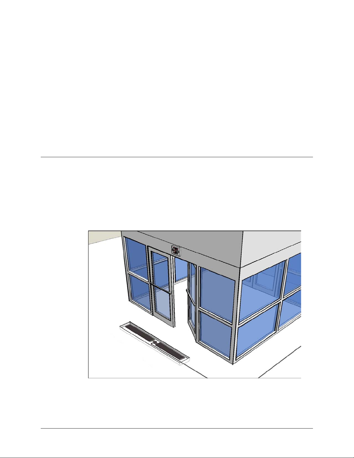
This manual instructs in the planning, installation and config uration of the EVO LVE F10 System.
Figure 1.1 F10 System Introduction (F10, 2 meter installation shown)
F10 Installation Manual Rev.*60 9 of 71
Page 10
Overview
This chapter explains F10 system hardware. This genera l information is useful for initial planning
and training purposes.
1. Hardware: Shows hardware component s including t he antenna assembly and electronics.
2. System Diagrams: Shows overall design and component layout of the F10 system.
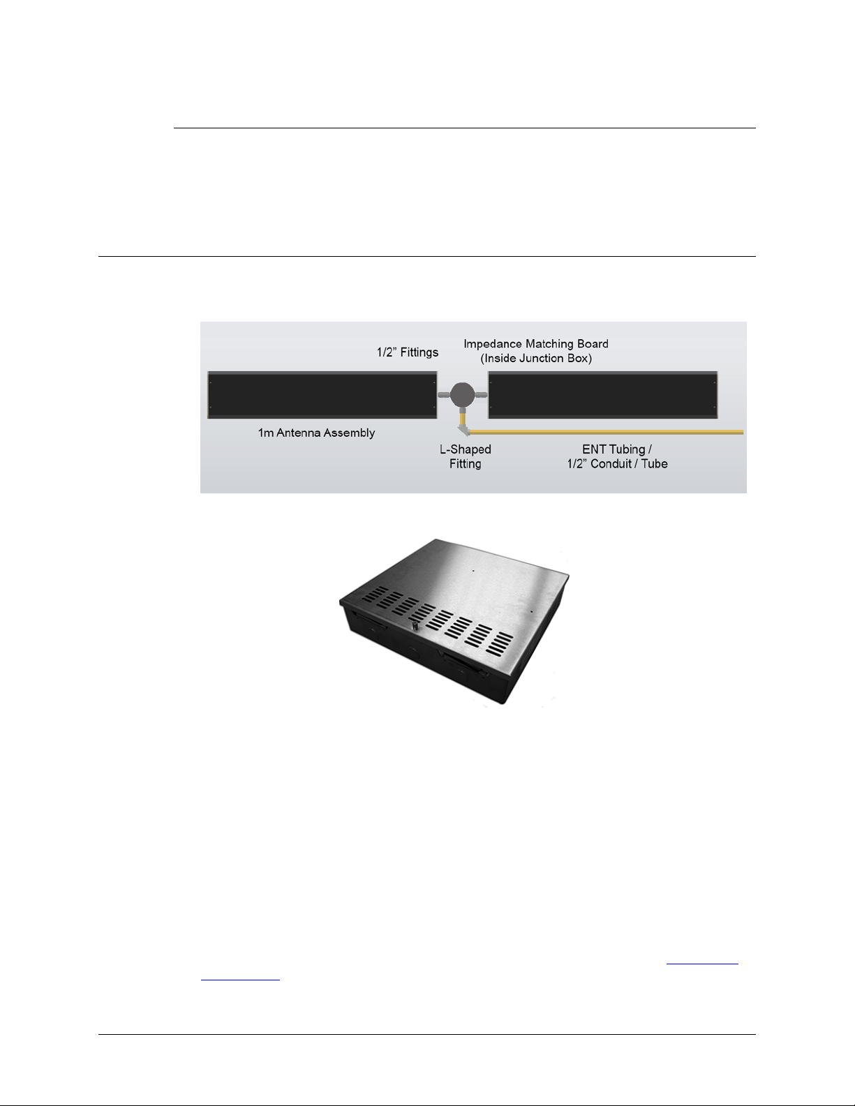
F10 System Hardware
The F10 sy stem is designed to be installed in the floor and provide an invisible EAS system. The
basic design is a 1 meter antenna assembly. Each antenna features multiple shielded coils. A
single assembly or two (2) units can be connected to a single Impedance Matching Board.
Figure 1.2 F10 Hardware
Figure 1.3 TR4215 Electronics Enclosure
The F10 system consists of a transceiver-based system using pulse/listen technology, allowing
them to work in a single antenna configuration. In the same way that the NLG FX2012 system
works, F10 antennas connect to a remote electronics enclosure via a coax cable.
The antenna is wired directly to an Impedance Matching Board, another component that is
installed in the floor (i.e. buried along with the antenna). The Impedance Matching Board
provides the link between the antenna wirin g and coax cable that connects to the remotely
located electronics enclosure. Typical EAS peripherals are able to be incorporated.
O
The electronics enclosure is designed to ensure proper ventilation in a non-condensing 0-40
environment. The wiring for the electr onics system is a low-vo lta ge, limited-energy system
(operating at 24VDC or less). All wiring must conform to applicable wiring codes.
The F10, 2 meter kit includes one (1) Impedance Matching Board for connecting the two (2)
antennas to a single Electronics Enclosure via two (2) coax cables routed through a single piece of
conduit. The power supply unit (not shown) is the standard +24VDC unit (refer to
Power Supply).
F10 Installation Manual Rev. *60 10 of 71
Appendix A:
C
Page 11
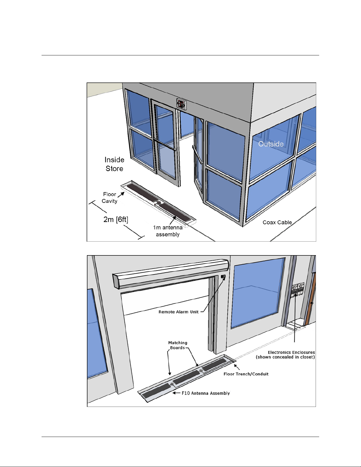
System Diagrams
The F10 system uses an antenna assembly comprised of wire coils wrapped around ferrite material
tiles. Antennas
Figures
are enclosed in PVC casings for strength and protection from environmental factors.
1.4 and 1.5 show common installation coverage widths: 2m and 3m [6 and 9ft respectively].
Figure 1.4 Typical F10, 2 Meter Installation
Figure 1.5 3m [9ft] Installation Layout wi th Compon ent Names
F10 Installation Manual Rev. *60 11 of 71
Page 12
Grouping Multiple A ntennas
Larger aisles are able to be covered using a Sync configuration. Aisle widths of any 1m increment
are possible. The 3m configuration features an F10, 2 meter system and a single 1 meter system.
Similarly, the 5m layout features two (2) F10, 2 meter systems and the standard F10 antenna.
Multiple electronics enclosures and power supplies are required, in this case, and the system
electronics must be configured for operation as a single unit. Refer to the
Systems for Sync” section.
Multiple floor trenches are cut with each length of ENT tubing (conduit) spaced 5 .1 cm [2in] from
the next closest to reduce RF interference.
Although grouping multiple installation kits together is possible, it requires approval from
Checkpoint’s Product Management. Feasibility is confirmed during the initial planning stage
known as the “Site Survey.” If the Site Survey was already performed and at present you are
prepared with installation-specific details, please skip to
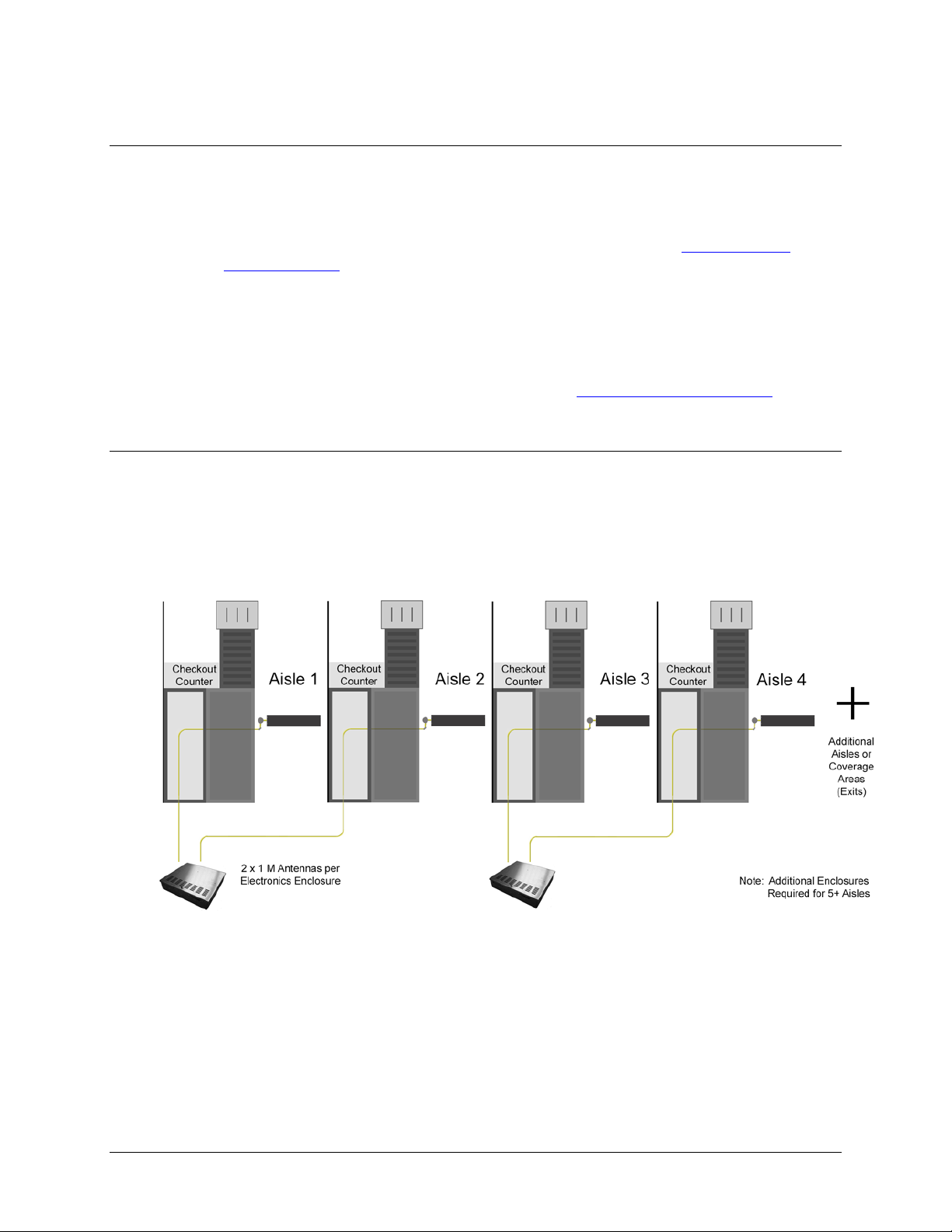
2 x 1 Meter Config uration
When necessary, two (2) standard F10, 1meter systems are connected to the same electronics
enclosure in a 2 x 1 meter configuration. The common application of the F10, 2 x 1 meter
configuration is in a grocery store or large department store. This setup allows EAS coverage
of many store checkout aisles, as well as single-door entrance / exit layouts. Each 1m antenna
assembly is fitted with a Matching Board. The layout minimizes the total number of electronics
enclosures needed when multiple F10 systems are used.
“Wiring Between
Chapter 3: Physical Installatio n.
Figure 1.6 F10, 2 x 1 Meter S ystem Diagram
F10 Installation Manual Rev. *60 12 of 71
Page 13
CHAPTER
SITE SURVEY
Overview
Checkpoint Field Service personnel vi sit the location to perform a site survey before installation.
The initial planning stage is the approp r ia te time to d e te rmine site suitability, where the antenna
loops will be located (for maximum EAS protection) and the type of systems to be installed.
Antenna Distance from Interf ering Elements
Nearby elements and underlying flooring materials may cause interfering effects. Therefore,
antenna placement must be carefully evaluated before installation. Your goal is to ide ntify a
location where ambient noise and environmental factors do not degrade system performance.
2
For repeatability, all measurements are given at baseline (i.e. using a standard tag type).
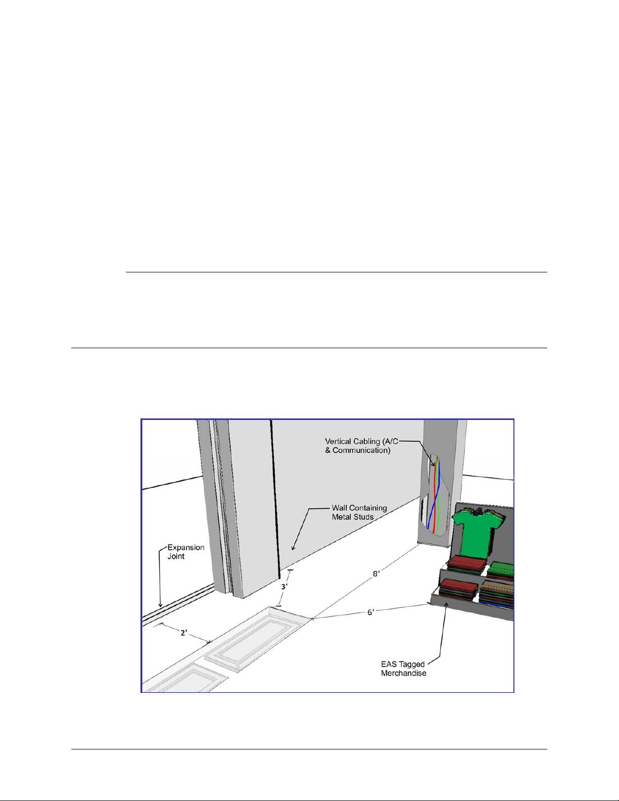
Figure 2.1 Distances from Interfering Elements
F10 Installation Manual Rev. *60 13 of 71
Page 14

Common interfering elements and their minimum distances from F10 Antennas are listed below:
Expansion Joints: The minimum distance fr om an expansion joint is 0.6 m [2 ft].
Vertical Cabling: The minimum distance from vertical cabling is 2.4 m [8 ft].
Metal Wall Studs: The minimum distance from a metal wall stud is 0.9 m [3 ft].
Sliding Doors (Metal): The minimum distance from a metal sliding d oor is 1.2 m [4 ft].
Tagged Merchandise: The minimum distance from tagged mercha ndise is 1.8 m [6 ft].
Inward and Outward Swinging Doors (Metal): The minimum distance from either a
manual- or automatic-swinging metal door frame is 0.6 m [2 ft].
Although this last type of door is not shown in the fi gure, the fact t hat swinging metal doors can
swing toward the antenna loop must be taken into account (see below).
Note: The antenna must not be located below the door (or too near the door) when fully opened. Locate the
F10 antenna components beyond the door – with a minimum clearance gap of 0.6m [24in].
Other Checkpoint equipment could interfere with the F10 system or vice se versa (refer
Appendix C: Interactions for recommended separation distances).
to
System Performan ce C onsiderations
Nearby wiring and lighting, as well as floor construction, may affect performance. With RF
interference that is too severe and cannot be alleviated, the site may not be suitable for any
installations.
The detection field is not uniform (refer to
Each of the following alters F10 system performance:
• Spacing between the antenna and steel deck in the floor can affect performance, but it
has been observed that an increase in detection can occur when the F10 system is placed
on any metal flooring.
• Floor structure may cause detection variation for the F10 system.
• Antenna configurati on will cause an e xpected (kno wn) change in detection hei ghts and
a unique coverage pattern. Refer to
• Signal strength - The plots in the appendix have a defined height at TX = 31 (the
maximum). If TX is less than 31, detection heights will decrease.
Appendix D: Detection Performance for diagrams).
Appendix D: Detection Performance for detail.
Determining the Electronics Location
During the site survey, evaluate the store’s layout to learn what options are available for locating
the electronics enclosure and power supply. The electronics and power supply may be placed close
together, although this is not required. Both units may be placed under a cashwrap counter, under
shelving, above a drop ceiling (see special requirements), or in a utility closet.
The updated power supply can be installed in the plenum (i.e., above a drop ceiling or in HVAC
areas), but this requires a conversi on kit (refer to
If necessary, the electronics enclosure can be located in the plenum – and as long as the power
supply is located outside of the plenum – no conversion kit is required.
Appendix A: Power Supply for complete details).
Note: Since the “Hood Kit” (CKP P/N: 7367100) must be ordered separately, determine whether or not one
is needed now.
Caution: If using the conversion kit, the power supply must be installed by a licensed electrician.
F10 Installation Manual Rev. *60 14 of 71
Page 15

Electronics Enclosure Placement Requirements
• Locate the electronics enclosure no further than 12.2m (40 linear-feet) or 15.2m
(50 cable-feet) from the antenna(s) to allow for bends in the conduit run.
• If wall-mounting is ideal, mount the electronics enclosure approximately 1.8m [6ft]
above the floor to reduce RF-interaction with wiring in either the ceiling or the floor.
Electronics mounted to the ceiling can potentially have a high RF-interaction with the surrounding
environment (e.g., metal rafters or power cables), and therefore, may not perform optimally here.
Observe locations of active noise sources including deactivators.
Environmental Considerations
F10 systems are only approved for indoor installations only. For a first floor (ground level)
installation where the slab will be on grade (i.e., directly above the natural ground), we
recommend the concrete be poured above a vapor barrier to prevent moisture from rising.
The store's architect will recommend the maximum permissible loading in the floor area where
F10 antennas are physically installed. The architect must consider such factors as anticipated
traffic over the floor and the material characteristics of the flooring (if covered by concrete).
The guidelines included in this guide assume installation into concrete (typical), but the antennas
may be placed directly on concrete if flooring, such as finished hardwood, laminate, tile or stone,
conceals the system below. If a wooden floor is placed on top of the system, the weight of the
floor should not rest on the antenna(s). Mo r eover, with all installations, the concrete and other
materials above the antenna(s) cannot be metallic. For example, wire mesh cannot be used for
reinforcement above the concrete. Metallic walk-off mats should not be placed above the system.
Note: Tile grout and mortar used to fill antenna trenches MUST BE non-metallic and non-magnetic grout.
Another environmental consideration is a metal security gate. For installations where the drop
down or sliding gate could cause a phantom alarming issue, a Badge Board II (CKP P/N 7528451)
and a Gate Inhibit Switch (CKP P/N 7140188) should be installed. Discuss with P roduct
Management and customers.
As for the electronics, typical indoor conditions must be met. Operating temperature is 0°C to
+40°C [32° to 104°F]. Permissible humidity range is 10 to 75%.
Site Survey Con clusion
Overall, the site surve y is an opportunity to gather details and share information required for the
proper installation workflo w. B e for e le a vin g the test site, the location of the electronics enclosure,
floor cuts (trenche s or “channels ”), and/or conduit runs (see note) should be documented.
Using the in formation in the following chapter, draw up a plan with exact dimensions. In addition
to floor cuts, the power outlet lo c a tions (or hardwire into electrical for plenum i nstallation) should
be planned. Coordinating with site contractors facilitates easier installation.
Note: For the F10 System, it is required that the coax cable is ran through ENT Tubing (conduit).
Communicate with the contractor (and/or store personnel) before concrete has been poured. This
crucial action will allow the coax cable to be easily routed through the conduit.
Caution: Ensure wire run does not exceed the maximum distance to the electronics’ planned location.
F10 Installation Manual Rev. *60 15 of 71
Page 16

CHAPTER
3
PHYSICAL INSTALLATION
Chapter Outline
This chapter offers dia grams and lists step s for physical insta lla tion of the major system hardware:
1. Requirements: Lists the tool and part req uire ments for a typical installation.
2. Installation Outline: Lists all of the basic installation steps as a sequence.
3. Cut Diagrams: How to plan/make cuts for proper installation of the antenna assembly,
Impedance matching board, and plan/route the wiring of the coax cable.
4. Mounting the Electro nics: How to install the electronics enclosure and power supply.
Requirements
Tools
The following tools may be required for F10 system installations:
Arrow T-25 Staple Gun
Diagonal wire cutter
Hammer drill with 3/16” and 1/2 ” bits
Extension cord
Tape Measure
Hammer
Marker, Black Felt
Ratchet driver with 9/16” socke t
Screwdrivers: mini, regular and #2 Phillips
Hacksaw
Utility knife
Wire Snake
Wire Strippers
Wrench, combination end 9/16”
Checkpoint Systems Field Service Diagnostic Management Software (DMS version
1.8.31 or later version) installed on a laptop with the appropriate cables.
F10 Installation Manual Rev. *60 16 of 71
Page 17

Parts
Quantity will vary according to syste m type.
18 AWG 2-conductor (STP) Power
22 AWG 4-conductor (STP) (5594) Sync
PVC cement
*DekDuct (wire chase)
*Wiremold (1500 or 2600 series)
*Wiremold anchor bolts
Note: *Wire routing methods will vary by installation.
Note: Complete parts lists with OEM Part Numbers are included in Appendix B: Part Lists.
Installation Outline
Follow this sequence to successfull y i nstall the components and validate system op e r a tion:
1. Determine optimal antenna placement:
a. Perform a site survey now, or
b. Use the resul ts of a previous survey.
2. Determine power supply req uirements and the ideal location for s ystem electronics.
3. Physically install the antenna(s).
4. Route/connect the antenna (coax cable) and applicable wiring (sync, alarm, power).
5. Install the peripherals and wire the device(s) to the electronics enclosure.
6. Configure the system using DMS.
7. Perform system specific tunin g (te st jump positions).
Antenna Installation
Antenna installation and tuning is performed by trained Checkpoint personnel. You have already
determined the system model(s) and number of assemblies for install, or you recently received this
key infor mation from a prior survey. If you are unsure of any specifics, contact Checkpoint Projec t
Management.
During Construction
If the floor has not been poured yet, a pre-fabricated trough can be constructed. Refer to Figures
3.3 and 3.4. In the event of a new construction, please convey the following information to the site
contractors (construction team’s foreman) or the manager responsible for pouring the concrete:
• Location where antenna (s) will be placed; define a reference point (such as a door frame).
• The exact dimensions of antenna(s); provide the appropriate Floor Cu t diagram(s).
• The depth, length and pathway of the 1/2” ENT Tubing (conduit), if installed ahead of
After Constructi on
For sites where floor cuts must b e made, convey the fo llowing instructions to the installing
technician. Communicate all known specifics to the installer, referring to the diagram(s). Be sure
to convey plans and instructions for the correct system type. Only provide the floor layout(s) for
required antenna configuration(s). If using a chisel, rough / uneven floor cuts may occur. Flatten
the bottom surface on which the antenna rests with either leveling sand or a layer of concrete fill.
Install the antenna(s) i n the proper location(s) discovered during the site survey.
time; depth of the trench for routing the cable is 3.8cm [1.5in] deep.
F10 Installation Manual Rev. *60 17 of 71
Page 18
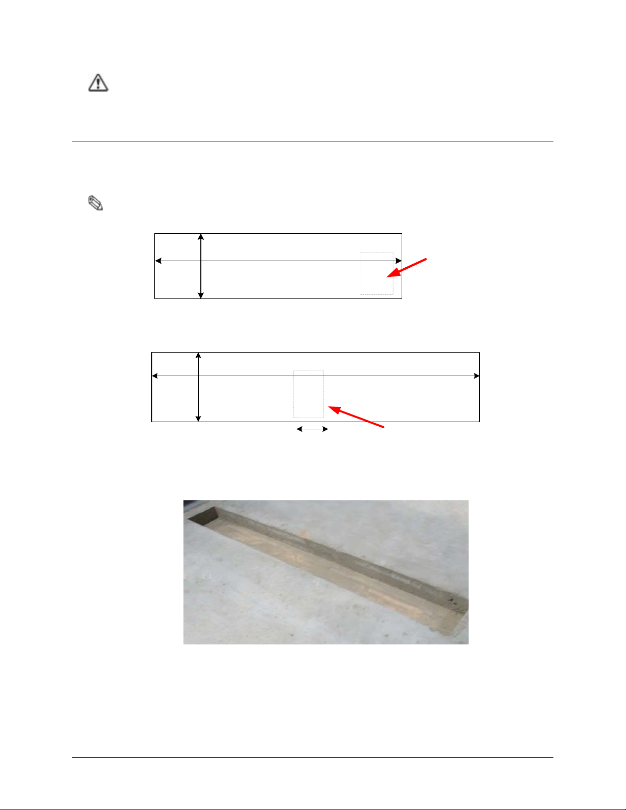
Caution: Prevent uneven stress on the fragile electronic components inside the assembly by ensuring the
127.6cm [50.25in]
35.5cm
[14in]
F10 Matching
Board Location
F10 Matching
Board Location
21.8cm [8.6in]
234.5cm [92.33in]
35.5cm
[14in]
floor trough is smooth and level. Fill in uneven areas or gaps with leveling sand or concrete filler.
F10, 1 Meter and 2 Meter Floor Cuts
Installing the F10 antenna assembly in an existing store requires a trough to be cut in the floor.
If the site is under construction, it is easier to mold the system into the floor (explained above).
These diagrams include details o n the size of the trough cuts required for each configuration.
Note: Figures are Not Drawn to Scale
Figure 3.1 Top View of F10, 1 Meter Floor Cut
Figure 3.2 Top View of F10, 2 Meter Floor Cut
Figure 3.3 Trough for t he 2 Meter assembly
F10 Installation Manual Rev. *60 18 of 71
Page 19
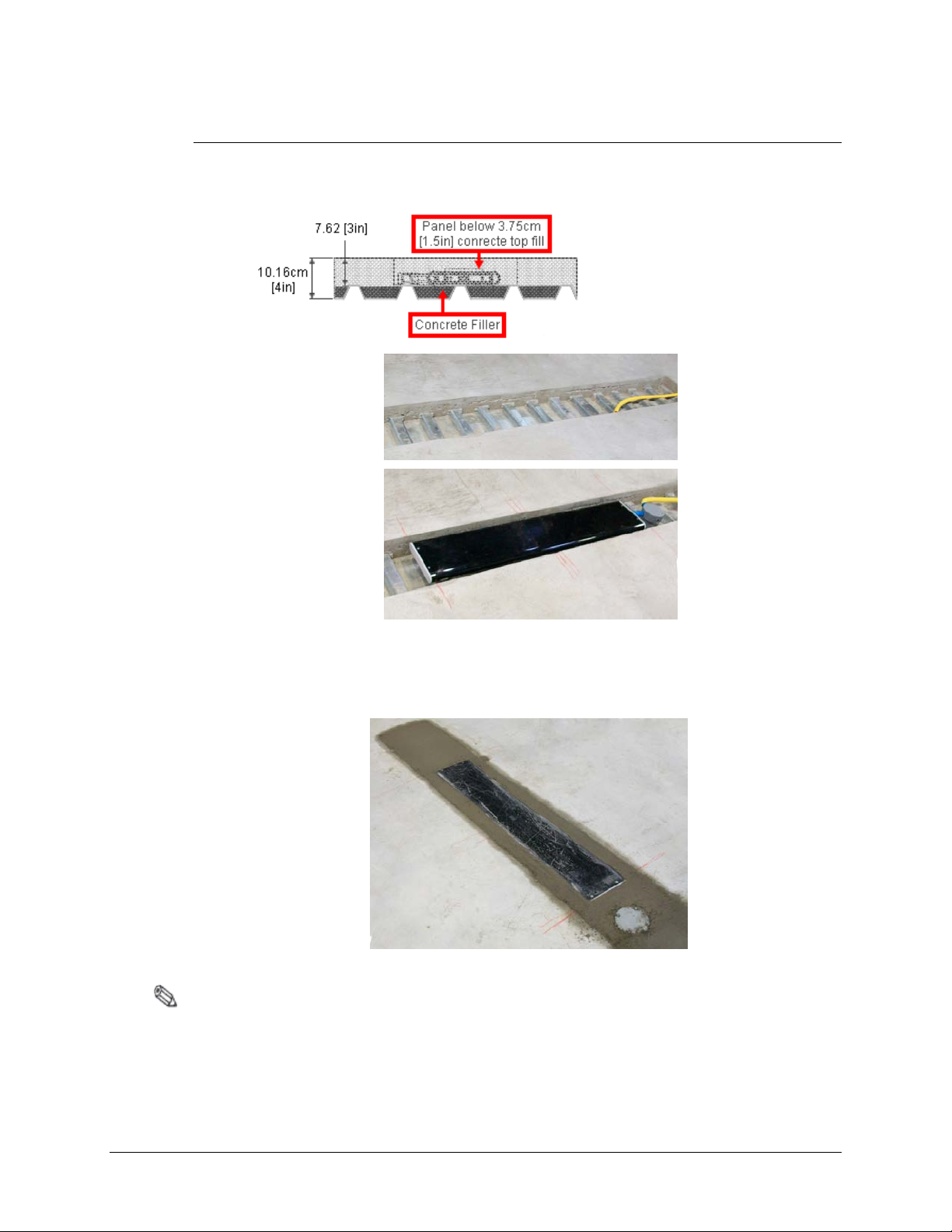
Floor Cut Depth
F10, 1 meter and 2 meter Antennas are identical, so the trough’s floor cut de pth (height) is always
consistent. Recommended depth is 7.6cm [3in] for optimum structural integrity. T his allows
approximately 3.75cm [1.5in] of concrete top fill covering each antenna (as shown in Figure 3.3).
Figure 3.3 Side View of Trough
Figure 3.4 Antenna Installed (not buried until a f te r testing)
In scenarios where the flooring does NOT physically allow such depth, it is acceptable to cover
the antenna assembly with less than 1.5 inches of concrete fill. Although it is uncommon, whe n
covering with tile or wood floo ring, the system can be installed flush to the concrete’s surface.
Figure 3.5 Flush Depth
Note: If installing in a location that violates the recommended 7.6cm [3in] depth specification, inform
Checkpoint Project Management.
F10 Installation Manual Rev. *60 19 of 71
Page 20
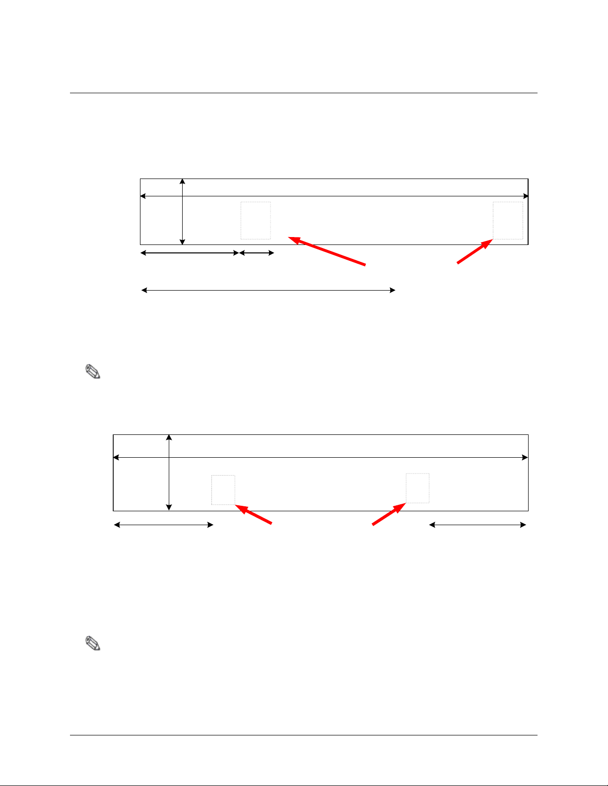
Common Wider Floor Cuts
354.5cm [139.6in]
Matching Board
Locations
117.5cm
[46.27in]
224.2cm [88.3in]
35.5cm
[14in]
21.8cm
[8.6in]
461cm [181.5in]
Matching Board
Locations
35.5cm
[14in]
117.5cm
[46.27in]
117.5cm
[46.27in]
It is possible to create a wider system by combing either of the smaller two floo r kits (refer to
Figures 3.1 and 3.2 above). For example, to cover a 3m mall op eni ng, a 1 m and 2m kit are ordered.
Figure 3.6 below shows exact dimensions of the trough (floor cuts) when the F10, 1 meter and 2
meter systems are combined. Figure 3.7 shows two (2) F10, 2 meter systems installed side-by-side.
Figure 3.6 2m and 1m System for 3m Opening
Note: Figures are Not Drawn to Scale
Figure 3.7 Side-by-Side 2m Systems for 4m Opening
Note: The Impedance Matching Board placement for the F10, 2 meter system is between the assemblies.
For the F10, 1 meter system, board placement is beside the antenna assembly. The ENT Tubing
(with coax cable) can be routed in any direction from antenna to electronics. A minimum spacing of 2”
between the antenna and tubing is required.
F10 Installation Manual Rev. *60 20 of 71
Page 21

Mounting the Electronics Enclosure
Detailed instructions for mounting the Electronics Enclosure are below. Before installing the
enclosure, review the fol lowing requirements and i f necessary, consult the Sit e Survey res ults.
It is suggested if the location is difficult to access, wire the system before mounting, but keep the
power suppl y unpl u gged unt il fi nis he d wir in g all per ipherals and mounti ng the support brackets.
The electronics enclosure must be located no further than 12.2 linear-meters [40 linear-feet ] from
the antenna(s) to allow for bends in the 15.2 cable meters run [50 cable feet]. The enclosure, which
weighs 5.17kg [11.4lbs], has keyhole slots at its edges to facilitate wall-mounting, but the
enclosure must have 2.5cm [1 in] clearance on all sides. Do not mount the electronics enclosure
beneath potential water sources (e.g. a sprinkler or pipe).
It is suggested to locate the enclosure directly above (or nearest to) the conduit’s endpoint, so the
length of exposed coax cable is minimal. Limiting exposed cable prevents RF interference, but do
not cut the coax cable (refer to the
Using the includ ed ENT Tubing (flexible conduit is supplied in the kit), route the cable from the
matching board to the arrival point near the electronics enclosure.
Installation procedures are listed for each type of material on which the enclosure can be in stalle d:
• Wood Surface,
“Placement” section in Chapter 4: Wiring).
• Drywall, and
• Concrete.
F10 Installation Manual Rev. *60 21 of 71
Page 22
Wood Surface Installation
1. Using the proper diameter bit, drill a hole into
1. Insert either # 2 or # 3 Phillips driver bit into
For mounting to wood, use a #7 x ½” (0.38cm x 1.3cm) hex head screw (CKP P/N 7939172).
the base material to a depth of at least 0.6cm
[1/4”] deeper than the embedment required.
Blow the hole clean of dust and other material.
2. Select the installation tool and drive socket to
be used. Insert the head of the screw into the
hex head socket driver.
3. Place the point of the screw through the fixture
into the pre-drilled hole and drive the anchor in
one steady continuous motion until it is fully
seated at the proper embedment.
Figure 3.8 Wood Surface Installation
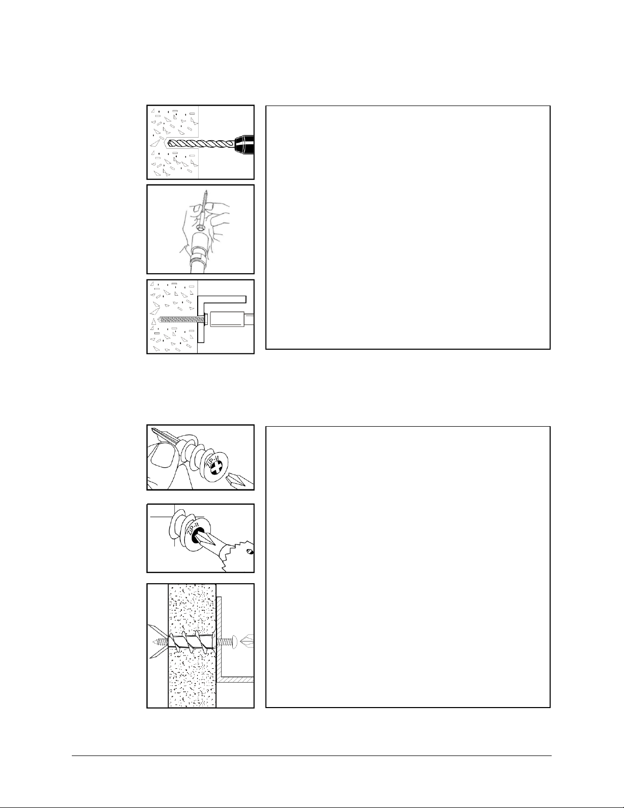
Drywall Surface Installation
For mounting to drywall, use a #8 x 1” (0.42cm x 2.5cm) panhead screw (CKP P/N 7308823),
which is a Power Fastener Zip-it (P/N 02348).
the recess of the ZiP-It anchor head. Use a
manual screwdriver or a low-rpm
battery-powered electr ic s crew gun.
2. Push the ZiP-It anchor into the surface of the
wallboard until the two cutting blades
penetrate the surface. Usi ng gentl e forw ar d
pressure, rotate the ZiP-It until the collar sets
flush to the surface of the wall.
3. Put the fixture in place, insert screw and
tighten until it feels secure. As the screw is
threaded into the nylon versions, the point will
expand resulting in increased load capacity in
thicker wallboard.
Note: When using an electric screw gun for
application, set clutch and use a slow speed
(do not exceed approximately 300-400 RPM).
Figure 3.9 Drywall Installation
F10 Installation Manual Rev. *60 22 of 71
Page 23

1. Drill a hole into the base material to the depth
Concrete Surface Installation
For mounting to concrete, use a 5/16” lead anchor and a #12 x 1 ½” panhead screw (CKP P/N
366291). Lead anchor (0.79cm) is a Power Fastener (P/N 09439). Screw is 0.55cm x 3.8cm.
required. The tolerances of the drill bit used
should meet the requirements of ANSI
Standard B212.15.
2. Blow the hole clean of dust and other material.
Insert the anchor into the hole until the flange
is seated flush with the surface of the base
material.
3. Position the fixture. Insert the screw tip
through the fixture into the anchor and tighten.
Mounting the Power Supply
The power supply should be mounted near the electronics enclosure, or in a remote location, when
available space is limited. If the power supply is installed above a drop ceiling, the Conversion Kit
is required (see below). For the unit’s weight and dimensions, refer to
GS-599ES(R) Installation
Hold the unit in place and mark the screw hole locations. Secure the power supply in its location
in the same manner as before (refer to the
GS-599MC-KIT(R) Installation
Refer to Appendix A: GS-599MC-KIT(R) for the complete hood kit instr uctions.
Figure 3.10 Concrete Installation
Appendix A: Power Supply.
“Mounting the Electronics Enclosure” section).
F10 Installation Manual Rev. *60 23 of 71
Page 24

Finishing Installation
Wiring the electronics, and configuring and tuning t he antennas must occur be fore finishing the
physical installation. Proceed to Chapters 4, 5 and 6, complete the setup and validation, and then
return to this section when ready to finish the physical installation.
Filling Trenches
The floor c uts or cavities are filled with concrete mortar, grout, and/or sealants during this final
step, ensuring the antenna locations are not visible. It is crucial that the grout be non-metallic and
non-magnetic. Occasionally (F10 system below wooden flooring), the antenna system is not
covered by Checkpoint personnel, as it will later be covered with flooring. Protect, as necessary.
The F10 system has been tested and is approved to be used with the following concrete repair
mortars and mixes:
1. Ardex TRM – Transportation Repair Mortar
2. QUIKRETE® Concrete Mix (No. 1101)
3. QUIKRETE® Fast-Setting Concrete Mix (No. 1004)
Note: Detection performance of the system may be temporarily affected by the water content in the repair
mortar. As the mortar mix cures, detection performance improves.
F10 Installation Manual Rev. *60 24 of 71
Page 25

Overview
CHAPTER
4
WIRING
This chapter instructs on the wiring of the entire floor system. There is a progression from the
antenna to the electronics enclosure and common peripherals. Chapter 4: Wiring concludes with
the DC power supply connections and system sync (optional) wiring sc he mes for multi-antenna
configurations (i.e., when two or more electronics enclosures are synced – to operate as a unit).
CAUTION: This system uses TR4215
that only TR4215 electronics can be used in conjunction wit h this system.
DMS versio n 1.8.31 or la te r must be used to configure the system after wiring is complete (refer
Chapter 5: F10 System Configuration via DMS).
to
The outline below is a sequence of the F10, 1 and 2 meter system wiring procedures :
1. Antenna Wiring
a. Components and Placement
b. Wiring the F10, 1 and 2 meter Antennas to the I mpedance Matching Board
2. Electronics Chassis
a. Coax cable Wiring to the Coax Adapter Board
b. Remote Voice Alarm Group Wiring
c. Alarm Post Wiring
d. DC Power Supply Wiring
e. Sync Cable and Power Wiring
†
electronics with firmware version 4.00 or higher. It is critical to note
F10 Installation Manual Rev. *60 25 of 71
Page 26

Antenna Wiring
Wiring Components
The components involved in Antenna Wiring and Coax Cable routing are shown below.
Note: The Impedance
Matching Board (right)
only fits in the junction
box in one position. Do
NOT it force into place.
Placement
Unpack the antenna (s). Each antenna has four (4) colored wires that stick out from an end.
1. Apply the rubber o-ring over the threads of t he ½” inch male fitting. Do NOT apply PVC
cement. Feed the antenna wires through the male fitting, then tighten. Screw one (1) fitting in
per antenna until rubber o-ring is compressed.
2. Position the antenna(s) in the floor trough, carefully lowering each into place.
3. Install the 1/2” ENT tubing (conduit). The tubing must cover the entire coax cable run from
the electronics to the antennas. Cut the tubing as required.
F10 Installation Manual Rev. *60 26 of 71
Page 27

4. Route the coax cable from the Electronics Enclosure to the floor trough. Do not cut the cable
yet, but note that excess will be removed after the true length is determined.
Caution: Cable must not be cut shorter than 30’.
5. Unpack the remaining system components including the Junction Box, lid, Impedance
Matching Board, PVC fittings and ferrite cores.
Wiring the F10, 2 Meter System
Perform the following to wire the F10, 2 meter system to the Impedance Matching Board.
1. Identify the “top” of the J unction Box (with the Carlon® logo facing up) and position the box
as shown. Remove the left, right and bot tom knockouts from the Junction Box. Use a hammer
and a large screwdriver as shown.
Caution: Ensure the correct knockouts (3 sides shown) are removed for the 2 meter system (only 2 for 1
meter system). Since the 2 meter uses both TX1 and TX2 sets of input connectors, set up is different.
2. Apply the rubber o-ring over the threads of t he ½” inch male fitting. Do NOT apply PVC
cement. Screw the fitting into the opening wher e the knockout was located until rubber o-ring
is compressed. Repeat for the other locations; tighten three (3) fittings in total.
3. Identify the colored antennas wires. Twist together loose strands of any frayed wire.
4. Select any four (4) small ferrite cores (CKP P/N 7221412).
5. Group the Yellow and Green wires together. Thread each individual lead through the same
opening in each of two (2) Ferrite cores. Repeat for the set of Red and Black wires as shown.
6. Using a utility knife
(shown at far right),
cut two (2) pieces of
conduit with six (6) ring s
for each (approximately
2.54cm [1in] in length).
Cut a third piece approx.
7.5cm [3in] long. This
section connects at the Lshaped fitting (see Step 10).
F10 Installation Manual Rev. *60 27 of 71
Page 28

7. Align the four (4) ferrite cores in a row; they fit when sta gge r ed (i.e., positioned end-to-end).
Thread the antenna wires through the piece of conduit. P ush two (2) of the Ferrite cores into
the antenna fitting. Apply PVC cement t o the outside surface of the tubing, then push hard on
the tubing, securing it t o the antenna fitting.
Note: Follow PVC cement instructions for proper surface preparation and use.
8. Apply PVC cement to the exposed piece of tubing. While holding the antenna in place,
push the Junction Box in until the fittings touch and form a tight seal.
9. Repeat this process for the other 1m antenna assembly. Refer to Steps 3 - 4 and 6 - 8.
Note: The four (4) antenna wires are later attached to the left side connector shown below.
Attach the coax cables first to provide better access and ensure no wires come loose.
F10 Installation Manual Rev. *60 28 of 71
Page 29

10. Route the coax cable through the L-shaped fitting and 3 inch piece Tub ing (cut to length).
After antenna placement is finalized, apply PVC cement and secure the section of Tubing.
11. To prepare the coax cable, strip the outer insulator, then twist the conductor into a wire lead.
12. Next, cut the inner insulator flush with the outer and strip ¼ inch of the s heathing around the
inner cond uctor (above right). Ensure that conductors are short enough to prevent touching.
13. Using a small screwdriver, gently hold the connectors open and then insert the coax wire
leads. Repeat for the second coax cable. Ensure that both inner and outer conductors match.
14. Make the antenna wiring connections to the matching board as shown (or refer to Table 4.1).
F10 Installation Manual Rev. *60 29 of 71
Page 30

15. The right side antenna is wired in reverse. Red connects to pin 1, yellow to pin 2, etc.
Side Pin Number Antenna Wiring
Antenna 1
(Left)
J2-1
J2-2
J2-3
J2-4
Antenna 2
(Right)
J2-1
J2-2
J2-3
J2-4
Table 4.1 F20 Antenna Wire Pinout
16. Verify the correct pin-out using the above table.
Green
Black
Yellow
Red
Red
Yellow
Black
Green
Note: Before closing the lid, it is necessary to first evaluate system performance. Refer to Evaluate Jumper
Positions.
17. Ensure that all the connections are secure (gently pull on the leads at the connection point to
the circuit board). Carefully position the wires inside, then close the Junction Box lid (tighten
all 4 screws). Be careful not to tear or twist the foam gasket on the lid when tightening the
screws.
Note: In instances where multiple electronics and coax cables are used, ensure that floor trenches or
conduits are spaced 5cm [approx. 2in] apart.
F10 Installation Manual Rev. *60 30 of 71
Page 31

Wiring the F10, 1 Meter System
The procedure for wiring the F10, 1 meter system is consistent with the 2 meter procedure with
two (2) important differences. First, preparing the junction box; second, wiring the matching board.
Instead of three (3) of the knockouts being removed, only two (2) are removed (see below)
Antenna wiring is different; only one (1) coax cable is utilized, howeve r, both connectors
(left and right) on the Impedance Matching Board are used (see Table 4.2 for F10 system).
Varied Procedure Steps
1. Identify the “top” of the Junction Box (with the Carlon® logo facing up) and position the box
as shown. Instead of removing both sides, remove ONLY one (1) knockout from the Junction
Box (side closer to antenna) a nd the bottom knockout. Use a ha mmer and a large screwdriver.
Note: You may remove the left or right, but ONLY one (1) side knockout is removed.
2. Only one (1) small piece of conduit needs to be cut.
3. Perform Steps 2 – 10, but skip Step 8 and unnecessary actions (related to the second antenna).
4. Prepare one (1) coax cable for the 1 meter system. Wire the coax cable leads to Pins 1 and 2
(left side) on the top connector.
5. Connect the antenna wires according to Table 4.2 below.
Side Pin Number Antenna Wiring
Antenna 1
(Left)
J2-1 Green
J2-2 N/A
J2-3 Yellow
J2-4 N/A
Antenna 1
(Right)
J3-1 Black
J3-2 N/A
J3-3 Red
J3-4 N/A
Table 4.2 F10 Antenna Wire Pinout
F10 Installation Manual Rev. *60 31 of 71
Page 32

Adjusting Jumper Settings
The default jumper settings for the F10, 2 meter system are OUT for J5 - J10.
The settings are adjusted for the F10, 1 meter system. Insert the red J5 and J6 jumpers.
Note: Later on, after the system is initially configured, each of the jumper positions are tested in order to
optimize the tuning of the F10 antenna. Refer to
Evaluate Jumper Positions and complete the test.
Wiring the 2 x 1 Meter System
For the 2 x 1 meter configuration, the wiring to each antenna is consistent with the F10, 1 meter
procedure. The main difference is there are two (2) coax cables routed to the electronics enclosure.
Route each coax cable separately through two different pieces of ENT Tubing. The lengths of
coax cable are connected to the two (2) male connectors on the A1116 Coax Adapter Board.
Note: In instances where multiple electronics and coax cables are used, ensure that floor trenches or
conduits are spaced 5cm [approx. 2in] apart.
F10 Installation Manual Rev. *60 32 of 71
Page 33

Overview
Electronic interfaces / connections to the TR4215 reader board are shown below. This section
describes how to wire all cables and ma k e the appro priate connections at the Electronics Enclosure.
Figure 4.1 TR4215 Board with all interfaces labeled
Coax Cable / A1 116 Wiring
The A1116 Coax Adapter Board connects to the F10 antenna via 15m [50ft] coax cable(s).
1. Connect the coax cable to the A1116 adapter board, then clip the Ferrite core (CKP P/N
7784420) over the cable(s).
Note: Ensure that the two (2) output jumpers
are in the Remote Position. J37 and J38
on the TR4215 board are located just
above the A1116 Adapter Board.
F10 Installation Manual Rev. *60 33 of 71
Page 34

Remote Voice Alarm
1. Connect the remote voice alarm wiring as shown below (or refer to Table 4.3).
Figure 4.2 Electronics Wiring: Alarm Group Relay
Note: Sync connections are shown. Not all systems will be synced.
Remote Voice Alarm / Alarm Counter
Wire Color TR4215 Connections
WHITE (RLY) J9-5
GREEN (RLY) J9-6
RED (+24V DC) J18-3
BLACK (Ground) J18-1
Table 4.3 Alarm Group Wiri ng Conne c ti o ns
2. Install the device and complete wiring at the peripheral device(s).
Refer to the peripheral’s Installation Instructions.
F10 Installation Manual Rev. *60 34 of 71
Page 35

Alarm Post Wiring
1. Connect the alarm post wiring as shown below (or refer to Table 4.4).
Figure 4.3 Alarm Post and Sound Wiring
Note: Sync connections are shown. Not all systems will be synced.
2. Install the device and complete wiring at the peripheral device(s).
Refer to the peripheral’s Installation Instructions.
Alarm Post Wiring
Wire Color TR4215 Connections
RED (Light + ) J43
BLACK (Light – ) J43
RED (Sounder + ) J11
BLACK (Sounder – ) J11
Table 4.4 Alarm Post Wiring Connections
F10 Installation Manual Rev. *60 35 of 71
Page 36

24VDC Power Supply Wiring
Wire Color
Description
Black
GND
Red
+24 V
Below are ins tr uct i ons fo r wir ing the 24VDC power supply to the TR4215 board’s DC Input Filter.
1. Cut the MC Armored cable (or generic AWG18 plenum-rated power cable) to length.
2. Strip the 2 (two) leads exposing about 0.6 cm [0.25 in] of the conductors.
3. Apply a Ferrite Core (CKP P/N 7284760) on the power wire near the DC Filter board;
complete 3 loops.
4. Apply the Ferrite Core (CKP P/N 7284760) to the AC power cord.
Figure 14.4 AC Power Cord Ferrite
5. Connect the lea ds to the DC inputs as shown (or refer to Table 5.5 below).
Figure 4.5 Power Supply connections
(for a Single-Antenna System)
Figure 4.6 DC Power Filter
_______ (Parallel outputs on left and right)
F10 Installation Manual Rev. *60 36 of 71
Table 4.5: Power Cable Wiring
Connections
Page 37

Wiring Between F10 Systems for Sync
Where multiple-antennas are installed, a secondary electronics enclosure is connected to a primary
via a sync cable. The RF Sync cable is installed prior to configuration. Use 22 AWG 4-conductor
(STP) (5594) cable for sync cable. Parallel or “Daisy Chain” wiring configuration allows a single
power supply to operate both units. Use 18AWG plenum-rated cable for the power connection.
Caution: If there are more than two (2) electronics enclosures, additional power supplies are required.
Figure 4.7 Multi-Antenna Systems
Sync Cable and Power Supply Wiring
1. Connect the Sync output cable to terminal (J22) to Sync Input terminal (J20) on the secondary
electronics unit.
Figure 4.8 Sync In / Out
Terminals
Note: This would be a combined
system (with both IN and OUT
connections made).
F10 Installation Manual Rev. *60 37 of 71
Page 38

Sync Input/Output Connections
SYNC -
SYNC +
GND
Wire Color Description TR4215 Connections
White
Green
Black & Drain
Table 4.6 Sync Input/Output Wiring Connections
2. Prepare the short length of power cable and connect via Daisy Chain to the second electronics
enclosure’s DC +24V Input . Use MC Armored or generic AWG18 plenum-rated power cable.
Wiring peripher als
Use the appropriate installation manual for wiring to the peripheral devices.
For wiring and configuring th e Wireless Voice Alarm, refer to the Installation Instructions:
EAS Audible Alarm/Alarm Counter (CKP P/N 7186802)
For hardwiring the EAS Voice Alarm/Counter peripheral, refer to Section 3.1, “Wiring the liberty
PX,” of the Installation Instru c tions (CKP P/N 7226881).
J20/J22-1
J20/J22-2
J20/J22-3
F10 Installation Manual Rev. *60 38 of 71
Page 39

CHAPTER
5
F10 SYSTEM CONFIGURATION
VIA DMS
Overview
This chapte r reviews the c onfiguration steps for the F10 system using DMS. There are slight
differences between the 1m and 2m systems. Antenna tuning is covered in Chapter 6: F10 Tuning.
Please follow the tuning guide to optimize system performance after configuring the F10 syst em.
Note: Please use DMS version 1.8.31 or later. TR4215 firmware version must be 4.00 or later.
System Setup Using DMS
The DMS setup procedure varies between the two overall system configurations:
• Single-Electronics System (i.e. only one or two antenna assemblies) and
• Multi-Electronics System (more than two antennas must be synced when less than 12m
[40ft] apart).
Note: 12m [40ft] is the minimum distance where a sync cable is not required between two (2) separate
single-electronics systems, but this should be taken on a case by case basis. See
minimum distances to avoid interactions.
The instructions below emphasize which parameters should be setup for the TR4215 board. In
either case, setup is similar but an extra step is needed for Multi-Antenna configuration. A basic
knowledge of the DMS tool is assumed.
Note: Refer to the Field Service Diagnostic Management User’s Guide for general help using the DMS tool.
Single-Electronic System Setup
The basic setup process consists of following steps:
1. Make a new DMS connection.
2. Configure the electronic(s) for Detector mode.
3. Set up alarm responses based on customer needs.
Appendix C for
F10 Installation Manual Rev. *60 39 of 71
Page 40

Make a New DMS Connection
1. Connect the service PC laptop to the J48 serial port on the TR4215 board.
2. Launch the D MS program (version 1.8.31 or later) and enter your logi n in formation.
3. Make a new Connection for connecting to the TR4215 board. Be sure to select "(Direct)
Serial" for the Type and "Evolve" as the Device.
Unlike pre vio us Li be r t y Systems, NGL doe s no t use the "TR4024/26" Device Connection.
Figure 5-1 shows the "Add Connection" window with the appropr i ate NGL settings.
Figure 5.1 New Connection Setup
4. Click Next, a serial port selection window appears. Fill in the COM port parameters and
then click Next. The fina l connection summary window appears.
5. Click Finish to complete the new connection setup. A new ic on titled “NGL board”
appears in the DMS Connections window (shown in Figure 5-2).
Figure 5.2 NGL board Added as a New Connection
F10 Installation Manual Rev. *60 40 of 71
Page 41

Configure to ECO Mode
1. Using the DMS tool, connect to the TR4215 board. Figure 5-3 shows the opening screen
with the Network view expanded to show all devices.
Figure 5.3 DMS Network and Task Manager View
2. Navigate to the Switch Settings window (click Configure Settings, shown ab ove).
3. Under the Detection Tab, fill in the following parameters:
• RF Group Address: choose a n Address between 1 and 6. The address should
match any ot her reader.
• Sync Mode: set to "ECO Mode" for the F10, 1 meter system or 2 x 1m syste m.
For the 2 meter system, set the sync mode to “Detector” or “Primary Non ECO.”
• TX Control: set to Enabled, Mode 2.
Figure 5.4 Detection Tab, Switch Setting Parameters
F10 Installation Manual Rev. *60 41 of 71
Page 42

4. Click Apply.
5. Under the Tuning Tab, fill in the following p a rameters:
• Sampling Holdoff: Set to 13.
6. Click Apply.
Figure 5.5 Tuning Tab, Switch Setting Parameters
7. Under the Band Tab, fill in the following parameters:
• Frequency Band: Set to the application required by the customer. For more
information about the choices, refer to the "
Application-Based Detection
Modes" section.
• Edge Blanking: Set to 0-15.
• Master/Submaster: Set to "Master" for any Single-System.
Note: If configuring a Multi-Electronic System, later refer to "Multi-Electronic Systems (Sync Configuration)”.
• Q Band Detection: Choose a setting based on the type of tags used by the
customer (Hard tag, 410, etc.).
• Threshold Adjust: Set to either 16 or 0.
8. Click Apply.
F10 Installation Manual Rev. *60 42 of 71
Page 43

Figure 5.6 Band Tab, Switch Setting Parameters
9. Navigate to the Antenna Settings window.
10. Under each Antenna Tab, fill in the following parameters:
• Antenna Type: Set to Detector.
• Jammer Threshold: Set to 0.
• TX Maximum: Set to 31.
Note: The FCC requirement is TX=31 (same parameters as CE).
• RX Gain: Set to 31.
• RX Hardware Gain: Set to 31.
• Port Control: Check RX, TX and Port. Do not check AGC.
11. Click Apply.
Figure 5.7 Antenna Set t ings
F10 Installation Manual Rev. *60 43 of 71
Page 44

Note: If this is a single antenna configuration, click Antenna 2 tab, then set TX Maximum Power to 0 to turn
off the Transmitter.
Multi-Electronic Systems (Sync Configuration)
1. Repeat Steps 1-11 above (switch serial p ort connection to the other board). For the second
electronics system, set to Submaster on the Band tab.
2. Repeat with additional TR4215 boards until all units are configured for sync operation.
Application-Based Detection Modes
This section details the steps and options for device configuration with respect to specialized
application and SAM settings. The Evolve Firmware 4.0 supports both single- and dual-tag
detection modes. These modes allow the system to look for two different tag frequencies while
providing customized alarms for each
This section describes:
• Application mode concept and how it replaces earlier frequency band settings
• Extended alarming capability based on alarm severity levels
• Smart Alarm Management (SAM)
The framework for this capability is a new Application-based configuration model introduced wit h
Evolve Waimea firmware. The approach is a change from previous Liberty versions and will be
described in detail in the following paragraphs. With the new approach, an application is selected
rather than a specific frequency band.
Figure 5.8 Switch Settings Frequency Bands
Currently there are 10 supported tag / frequency ba nds, some supporting dual-tag detection while
the traditional applications still supp ort a single tag. In the case where an applicatio n supports two
tags, there is a primary tag and a secondary tag. The primary tag is most common (typically 8.2
MHz) and the secondary tag is typically used for higher prio r ity items or higher-cost items. In the
dropdown menu, the application name includes the center frequency for the supported tag(s).
F10 Installation Manual Rev. *60 44 of 71
Page 45

Standard: 8.2 and Library: 9.5
These are the standard applications and remain unchange d from the pre vi ous version o f the
firmware. Each application uses a ta g that falls wit hin a single contiguous RF frequency range.
• Standard: 8.2 is the most common a nd most generic application.
• Library: 9.5 mode is used primarily in libraries.
Corral: 8.2, 9.0
This application is used in Toys-R-Us stores where the 8.2 MHz tags are placed on general
merchandise throughout the store and 9.0 MHz tags are placed on electronics located in a special
“Corral” area in the store.
Reverse Corral: 8.2, 9.0
This is used in Barnes & Noble and is similar to the Toys-R-Us implementation but t he tag
frequencies are reversed. The 9.0 MHz tags are used for books throughout the store and the 8.2
MHz tags are used on other merchandise located in a “Corral” area.
Apparel: 8.2, 9.2
This application is used for stores where two levels of alarms are required to differentiate between
two priorities of merchandise. The system response is different (different light patterns or colors,
different sound patterns or voice alarm message) for each of the two tag types. The idea is to bring
special attention to the pedestal if the higher priority tag is detected.
Note: Previously, this was known as the “9.0 tag band” or “Kohls.”
Pharma: 8.2, 7.2
This application is used primarily in stores containing a pharmacy. By design, this application has
a very low false alarm rate for the 7.2 MHz tag.
RazorKeeper: 8.2, 7.2
This application is similar in use to the Apparel application but uses the 8.2 MHz and 7.2 MHz
tags. The 7.2 MHz tags are placed inside razor keeper boxes and when detected cause an alarm
response that differs from the 8.2 MHz tag response (different light and sound patterns and/or
specialized voice message).
Immunity: 8.2
This application is similar to the Standard: 8.2 application in that only the 8.2 MHz tag is detected.
The unique feature of the Immunity: 8.2 application is that it is much more resistant to false
alarms caused by merchandise than the Standard: 8.2 application. T his ap plication is especially
useful in hardware stores where a large percentage of the merchandise is known to cause false
alarms. If false alarming due to merchandise is not a severe problem, it is better to use the
Standard: 8.2 applicatio n b e c ause it will detect 8.2MHz tags over a larger frequency range than the
Immunity: 8.2 application. Tags which vary in range +/- 3% or more from the center frequency of
8.2 MHz may not be detected in the Immunity: 8.2 application.
F10 Installation Manual Rev. *60 45 of 71
Page 46

Japan I: 8. 2=9.5 and Japa n II: 8. 2, 9.5
These applications detect both the 8.2 and 9.5 tags with the same priority. In the Japan I
application, detection of either tag causes an identical alarm response (and is logged identically).
In the Japan II application, each tag causes a different alarm response (and is logged separately).
This application is being used to support a transition from predominantly 9.5 MHz tags on
merchandise to 8.2 MHz tags. These specialized applications are intended to aid in a smooth
transition during the change-over period.
Alarm Severity
Alarm severity levels are assigned to particular ta g / frequency bands based on different priority or
severity requirements (according to customer needs). This approach bases the alarm response on
the severity level of the alarm, rather than the frequency of the tag.
A total of four (4) levels of Alarm Severity are supported: Low, Medium, High, and Critical.
Default alarm responses for each severity level are explained below. However, specifics such as
lighting patterns and audible alarms can be customized using Smart Alar m Management (SAM)
(refer to “Configuring SAM (Smart Alarm Management)”).
Alarm Severity= Low: An alarm with a low severity is considered informational only. The alarm
will be logged in the event history as “Low.” No other alarm response (no lights, no sounder, no
output trigger, etc.) is associated with this level.
Alarm Severity = Medium: An alarm with a medium severit y is a “standa rd” alarm. Lights and
Sounder are activated. The relay associated with a group alarm (voice alarm) is also activated.
This is the alarm level typically assigned to 8.2 MHz tags. An alarm event logged as “Medium”
appears in the Event History display.
Alarm Severity = High: An alarm with a high severity is typically of higher priority than the
medium alarm. Default behavior is a different light or sound pa tte rn from the medium alarm (set
up in DMS) so that it may be differentiated from a medium priority alarm. The relay associated
with the group alarm (voice alarm) is activated for this alarm. An alarm event logged as “High”
appears in the Event History display.
Alarm Severity = Critical: An alarm with a critical severity the highest p r iority alarm and is
typica lly a covert or silent alarm. Default behavi or is no light, no sound resp onse and no group
alarm (voice alarm) trigger. Specialized Alarm behavior, if desired, must be set up in SAM. An
alarm event logged as “Critica l” a ppears in the Event History display.
Note: The behavior specified here for alarm severity of High or Critical is slightly different than the behavior
for the Evolve family because NGL does not have the Relay1 or Relay 2 dry contact relays that were
previously used for the Video relay.
Table 5.1 (on the following page) shows the Applications that are c urrently supported along with
the tag frequencies detected and the alarm severity assigned to each of the tag frequencies. In the
table “M” represents Medium Severity, “H” represents High Severity, and “C” represents Critical
Severity. There is no appl ication that currently uses the Low Alarm Severity level.
F10 Installation Manual Rev. *60 46 of 71
Page 47

Frequency Band
Frequency
Severity
Frequency
Severity
Primary
Secondary
Standard: 8.2
8.2 M -
-
Library: 9.5
9.5 M - - Immunity: 8.2
8.2 M - - Corral: 8.2, 9.0
8.2 M 9.0
H
Rev Corral: 9.0, 8.2
9.0 M 8.2 H Apparel: 8.2, 9.2
8.2 M 9.2 H Japan1: 8.2=9.5
8.2 M 9.5 M Japan2: 8.2, 9.5
8.2 M 9.5 H Pharma: 8.2, 7.2
8.2 M 7.2 C RazorKeeper: 8.2, 7 .2
8.2
M
7.2
H
Tag
Alarm
Tag
Alarm
Table 5.1 Alarm Priority Descriptions
Configuring SAM (Smart Alarm Management)
This chapter details the steps and options for configura tion of the Smart Alarm Management
(SAM) system in DMS.
Note: For information on installation and use of the DMS system, refer to the Field Service Diagnostic
Management User’s Guide.
Navigating to the SAM Screen
1. DMS should still be connected to the desired TR4215 reader.
2. Navigate to the Access screen (shown in Figure 5.9), whic h describes the current settings for
the antenna(s) in the group.
Note: Although previous Liberty systems required the "TR4024/26" Device setting in the DMS Connection
Settings window, NGL uses the "Evolve" Device connection.
F10 Installation Manual Rev. *60 47 of 71
Page 48

.
Figure 5.9 Network View of Antenna S ettings
Note: Detector 1 and Detector 2 (friendly name of antenna) will be shown instead of PAB-SAB.
Figure 5.10 Current Antenna Settings
3. Navigate to the SAM screen by either clicking the SAM icon on the toolbar (shown in Figure
5.11 below) after selecting Configure > Smart Alarm Management, or by pressing F9
(shown in Figure 5.12).
F10 Installation Manual Rev. *60 48 of 71
Page 49

Figure 5.11 DMS Toolbar with SAM Icon Highl ighted
Figure 5.12 Configure Menu in the DMS System
4. After the SAM screen (shown below) appears, the device is ready for configuration.
Figure 5.13 SAM Screen
Note: The pre-production version of the firmware only has the "Enable SAM" option available and not the
other two.
Below are on details all of the available options (if using a feature, select the applicable checkbox):
F10 Installation Manual Rev. *60 49 of 71
Page 50

• Enable SAM: This option button allows SAM to be Enabled (checked) or Disabled
(unchecked).
• Enable Sweeper Immunity: Select this option if a sweeper is nearby and affecting the
board's detection. During installation leave this optio n o f f until the system is tuned so that
that DMS A view will accurately show any interfering noise characteristics. Once the
system has been tuned, this option can b e set.
• Enable Noise Immunity: Select this option if there is Environmental noise causing false
alarms. This option will decrease the se nsitivity of the system in order to reduce the false
alarms.
Note: To enable an item, check the box before it. Only checked items will be set when Apply is clicke d.
5. Select the Options check box, then click Option 00 to enable SAM.
6. If the environmental conditions r e quire, select options 08 or 09. Refer to Chapter 6: F10
Tuning in order to determine if either or both of these options should be selected.
a. After selecting the require d options, click Apply to enable the features.
b. A prompt appears that confirms that the smart alarm parameters were successfully set.
Click OK; this completes the config ura tion of this portion of SAM.
Changing the Patterns
The second tab within the SAM screen is “Patterns.” Custom alarm events are configured here.
7. Select the Alarm Patterns checkbox to enable the pattern options. There are five (5)
configurable parameters designed to meet the customer’s alarm response requirements:
• Alarm: choose from light or sounder alarms.
• Priority: choose from a high or low priority signal.
• Beep Pattern: choose from a short, medium, long, steady, quick, very short, 2-beep,
3-beep, 4-beep, silent, *L (one short beep, one long beep), **L (two short beeps and
one long beep) beep pattern.
• Duration: choose how long (in seconds) the alarm either lights or sounds for each
alarm event.
• Intensity: select the intensity (volu me - sound) of an alarm event.
Note: If the alarm duration is set to 31, the pedestal will alarm continuously.
F10 Installation Manual Rev. *60 50 of 71
Page 51

Figure 5.14 Alarm Patterns Enabled
8. At the bottom of the Patterns tab are the Update and Add buttons used to configure Patterns.
If Add is chosen, the new alarm pattern appears in the list of existing alarm pattern (Light and
Sounder) as shown in Figure 5.15 below.
Figure 5.15 Previously Established Alarm Patterns
9. To Add, select the desired settings from the pattern settings created (r efer to Step 15). After
the alarm pattern settings are entered according to the customer’s specifications, add this
specific alarm pattern as a new alarm by clicking Add.
10. To Update, click and highlight the existing alarm p attern (that needs to be overwritten), then
select the desired settings and click Update.
Note: If Update is chosen, this overwrites the existing alarm pattern to the new parameters.
F10 Installation Manual Rev. *60 51 of 71
Page 52

Note: An alarm pattern may also be deleted at any time. Highlight the incorrect setting and click Delete.
Changing the Matrix
Alarm patterns are matched to antenna triggers via the Matrix tab. In the case of synced systems,
there will be two Matrix Tabs: "Matrix" and "Matrix 2". The two Matrix tabs allow the us er to
specify different behavior (light or sound) for the systems individually.
Figure 5.16 Matrix Tab
11. To activate the Mapping Matrix menu, select the Mapping Matrix checkbox.
a. From the “Trigger” drop down menu, select the event code to be altered or set.
b. From the “Action” drop down menus, choose from a sounder alarm pattern, a light
alarm pattern, no action, or output subnode.
c. Once the alarm pattern has been selected, choose from the different custom patterns
established in the previous step (Pa tte r ns tab), which are numbered to the right.
12. To finish coupling the selected alarm trigger with the custom alarm pattern, click Add. The
trigger appears in the right side window, where all of the a larm triggers and their alarm
response patterns are listed.
Note: As before, an alarm trigger and subsequent response can be removed by clicking Delete.
Note: Selecting 00 in the drop down box will use the Light or Sounder settings that are under the Alarms tab
in the Switch settings menu.
Updating the System
Once the system is properly configured, click the Apply button. This loads all the new alarm
settings, patterns, and matrices into the F10 system, updating it.
F10 Installation Manual Rev. *60 52 of 71
Page 53

CHAPTER
TUNING PROCEDURES
(1M AND 2M VARY)
Overview
This chapter describes the procedures required to properly tune the F10 system. It provides details
on identifying and measuring ambient noise levels. Before continuing, it should be stated that the
best way to remedy resonance is correcting the environment. The Impedance Matching Board for
the F10 system features jumpers that change capacitance and affect antenna tuning. Testing occurs
to optimize system performance. Refer to Appendix D: Detection Performance.
6
TR4215 Features
The TR4215 board utilizes advanced DSP (digital signal processor ) to automatically subtract
stationary resonances seen by the antennas. The center frequency and bandwidth adjustments are
preset for Standard 8.2 MHz operation. If the system is required to detect a different frequency tag,
the bandwidth select range must be adjusted by the CSE (installer).
The TR4215 is different from previous pulse-listen transceivers as it does not use jumpers, DIP
switches, or potentiometers to modify its configuration. However, there are jumpers used to set the
basic frequency tuning (8.2 vs. 9.0) for the transmitter output and another to terminate the RS-485
(for the sync connection). Refer to the
Chapter 4: Coax Adapter Board Wiring section.
Basic Tuning Methods Using DMS
All operating parameters for the TR4215 are controlled by Diagnostic Manager Software (DMS).
DMS diagnostic tools allow the CSE to identify and measure ambient noise levels, resonances and
other sourc es of environmental interfer ence.
1. Connect the service PC laptop to the J48 serial port on the TR4215 board.
2. Launch the D MS program (version 1.8.31 or later) and enter your login information.
Note: For detailed information, refer to the Field Service Diagnostic Management User’s Guide.
DMS is used to identify and correct noise and resonance. Often it takes a combination of the
following analog solutions to optimize performance:
• reducing power on the transmit antennas (TX1 and/or TX2);
F10 Installation Manual Rev. *60 53 of 71
Page 54

• reducing the baseband gain during software processing (RX1 and/or RX2);
• reducing the hardware gain (RX1 Hardware/RX2 Hardware); and
• adjusting t he receiver sampling hold off.
Digital readouts allow dif ferent points within the signal processing chain to be displayed through
the “C” view, or Set Filter Parameter Selectio n, whi ch is a passive setting. This particular tool is
used only after first attempting to correct the environ ment.
Front end gain (RF section) is reduced when a sweeper or other external noise sources are very
close to the pedestal and the RX1 and RX2 adjustments do not lower the emission seen in the Set
Filter Parameter Selection.
RX1 and RX2 Hardware gain adjustment allows a variable setting of the front end gain replacing
the gain jumper. There is also a soft LED for each receiver, RX1 and RX2, to indicate saturation
in the front end. Between t he RX Hardware gain adjustment and the soft LED, the CSE a ttempts
to find the point of saturation.
There are also internal noise problems (e.g., ringing) caused by board and antenna matching issues.
If the issue resu l t s from a low resonance close to the operating frequency range, this m ay be
resolved by increasing the gap (Sampling Holdoff) between transmit and receive cycles.
Note: For theory of operation and other detailed information on the different control settings, refer to the
NGL Installation Manual (CKP P/N 7360602).
The TR4215 board does not support inter-pedestal, Ethernet or modem functionality. Therefore,
settings for these features are not i ncluded in this document.
Noise Sources
There are generally two different types of noise sources our systems can encounter; asynchronous
and synchronous.
Asynchronous noise is random in nature and is found t hroughout the frame (signal and noise
channel) when certain devices are in close proximally. These sources may reduce detection and in
some cases, cause phantom alarms. Asynchronous noise sources could be any of the fol l owing:
1. CW Sweeper – These devices sweep throughout the detection band, degrading detection
performance, while causing false alarms. They usually have a constant linear sweep rate
(100Hz to 200Hz) with a certain high and low freque ncy range and a constant si gnal level.
2. Spiky Noise – This is usually from automatic door motors, (broken) lighting ballasts and
other pulse/ l isten systems that are not synchronized with the F10 system.
Synchronous noise is associated with items in close proxi mally to our system which resonate
during our transmission cycle and appear as a tag (with ring side down) to the detection system.
These present more of a false alarm threat when compared to asynchronous noise, especially if the
item is moving. They could also affect detection because of the complex mixing of the intended
tag signal and offending resonance. Synchronous noise sources could be any of the following:
1. Automatic Door Frames – In some cases metal doors will resonate and cause an emission
much like a tag ring down. When the door opens and clo s es, the background subtraction
(recall DMS) feature could be defeated, thus causing persistent false/phantom alarms.
2. Racks – Metal clothi ng racks will exhibit the same effects as door frames. When a rack is
moved, false alarms may occur.
Be aware that metal structures near the system may cause simil ar issues. Othe r sources of this type
noise could be merchandise close to, or passing through, our pedestals. In most cases merchandise
is most difficult to identify, because these items are meant to pass through the alarm region.
F10 Installation Manual Rev. *60 54 of 71
Page 55

Overall, the idea is to reduce the affects of the noise above by either reducing the noise at the
source or desensitizing our system to the source of noise. The following sections expla in the
appropriate tuning procedure(s) when a given type of noise is present.
Note: During installation leave the Sam Option "Enable Sweeper Immunity" off until the system is tuned so
that DMS A view accurately shows any interfering noise characteristics. After the system is tuned, this
option can be turned on.
Analog View
DMS offers a display that sho ws real-time data to assist the technician in adjusting the Reader for
optimal performance. Analog View is best for observing short duration noise, as well as stationary
environmental resonances.
For multi-antenna systems, sign a ls from primary and s econdary antennas are displayed on the left
and right. In the Analog Vi ew, four (4) different points within the signal processing chain can be
viewed. The Filter View switch controls which level of signal processing is displayed.
Typical Tuning Procedure
Since no real-world environment is free of random noise and resonances, tuning may be required.
This may involve adjusting TX Power, RX G ain and RX H ardware gain for the system antennas in
the following order:
3. Adjust TX Power for the antenna s according to the regulation maximum. For best
performance, TX Power should be set equal for both pedestals.
4. Flip to View D and adjust RX Gain individually for each pedestal, until the noise floo r
disappears under the Analog View.
5. Flip to View C and adjust RX Gain individually for each antenna until empty spots occur
(see notches in graph), indica ting disappearance of background resonances. Because of
the natural resonance fo r the TR4215, the view should look like Figure 6.1. The RX
Hardware gain usually does not need to be adjusted (and remains set at 31).
Figure 6.1 Typical Tuning on Filter C View
F10 Installation Manual Rev. *60 55 of 71
Page 56

Note: The TR4215 board exhibits some natural internal resonance around 8 MHz which does not need to be
tuned out. Because the signal is internal and the fact the Analog View is now multiplied by two (2), the
typical tuning curve looks like the above.
Evaluate Jumper Positions
System Specific Procedures
These procedures are specific to the particular model system being installed. Ensure the correct
procedure(s) are followed (i.e. run the correct test for either the 1 meter or 2 meter system).
For 2 Meter System
With the jumpers in the default p osition (OUT), assess detection height. If the detection
performance is ideal (i.e., alarm occurs at heights meeting or exceeding specifications listed), there
is no need to test the other jumper positions. If performance is less than ideal, insert the red
jumpers in positions J5 and J6. Repeat testing (flat carry). The detection test should be performed
using a 410EP tag (Super Hard Gen2 and Mini Hard tags are also acceptable). Test the maximum
detection at middle point (flat carry) by walking across the antenna at various heights and listening
to the alarm.
Note: During the detection performance test, the antenna should be disconnected from the DMS tool, as
computer connection can sometimes degrade the performance.
Next, compare measured to detection performance (alarm success rate at a given height) with the
jumpers in positions J7 and J9. Finally, test performance with jumpers in positions J8 and J10.
Leave jumpers in position for maximum detection.
After finalizing the jumper settings, connect DMS tool and check the Analog C view. Make sure
there is no excessive resonance (no more than 10 in the C view). If the resonance level is high,
then increase the Sample Hold Off up to 22 until the resonance level is reduced to less than 10.
For single 1 Meter or 2 x 1 Meter System
With the jumpers in the default p osition (J5 and J6 are both IN), assess detection height. If the
detection performance is ideal (i.e., alarm occurs at heights meeting or exceeding specifications
listed), there is no need to test the other jumper positions. If performance is less than ideal, move
the jumper positions from J5 and J6 to J7 and J9. Repeat testing (flat carry). The detection test
should be performed using a 410EP tag (Super Hard Gen2 and Mini Hard tags are also acceptable).
Test the detection at middle point by walking across the antenna a t various heights and list ening to
the alarm.
Note: During the detection performance test, the antenna should be disconnected from the DMS tool, as
computer connection can sometimes degrade the performance.
Next, move the jumpers to positions J8 and J10 and repeat the performance test. Leave jumpers in
position for maximum detection.
After finalizing the jumper settings, connect DMS tool and check the Analog C view. Make sure
there is no excessive resonance (no more than 10 in the C view). If the resonance level is high,
then increase the Sample Hold Off up to 22 until the resonance level is reduced to less than 10.
F10 Installation Manual Rev. *60 56 of 71
Page 57

Configuring the System for Asynchronous Noise
Active Saturation
Indication LED
RX Hardware Gain Control
Filter View A shows exc essive ‘spiky’ noise, which can also occur from a sweeper. This results in
poor tag detection as the output filter display (Filter View 'D') will bounce as much as ½ a divis io n.
Figure 6.2 shows the Analog View (Filter View A) displaying the noise. This view is directly fro m
the output of the ADC and is controlled only by the hardware gain (RF gain). Gain for filter views
C and D are also control by the RX gain (software gain). This is important because if the system is
saturated before the signal is processed (before the ADC, but after the hardware receiver), the RF
gain will need to be reduced. For cases when the TX control is disabled (customers using nondeactivatable tags), the RF gain sho uld be reduced until the Saturation Indicator LED is not lit.
This graph shows the Analog View with a sweeper 8 feet away from the submaster electronics.
Figure 6.2 Noise on Filter A View RX and RX Hardware Gain @ 31
If the TX Control is enabled, using the Satura t ion Indicator is not enough – additional RF gain
reduction could be necessary. To reduce the RF gain and attempt to resolve such a condition,
follow the steps below.
1. Observe the signal level (being shown in Filter Vi ew A) for about 15-30 seconds and
make a note of the highest level (peak response) during this period.
2. Reduce the RF gain until the peak response is only about one division. Below is a picture
after the adjustment.
F10 Installation Manual Rev. *60 57 of 71
Page 58

Figure 6.3 Noise on Filter View A – Result s After RF Gain T uning
3. After the RF gain is adjusted, observe Filter View D for about 15-30 seconds and note the
peak response during this period. Below is a picture before adjusting the RX gain.
Figure 6.4 Noise on Filter View D – Graph Before RX Gain Tuning
4. Adjust RX gain (software gain) until the Noise begins to peak into the Analog View D.
Figure 6.5 below shows a properly tuned system.
F10 Installation Manual Rev. *60 58 of 71
Page 59

Figure 6.5 Noise on Filter View D – Graph After RX Gain Tuning
Caution: In the presence of small resonances, this "spiky noise" will cause the system to false alarm.
Do not leave the system with this level of noise. The receiver gain must be set such that Filter
View D is nearly 'flat'.
Resonance Sources
A resonance is typically defined as a stationary signal in this FM band. When in the presence of
noise, a resonance may be ‘buried.’ By definition, Checkpoint tags are resonances (resonant
circuits). The system alarms on resonant circ uits on the pre-selected frequency. Once the receiver
is set to acceptable levels of noise, the system must be adjusted to eliminate resonances in the
environment.
The two types of resonances are environmental item and stationary resonances, described below:
• Environmental item resonances are items that can be moved. Examples of environmental item
resonances that must be eliminated include coils of wire, racks, wiring (Christmas lights) and,
of course, tagged merchandise. Environmental item resonances must be eliminated prior to
final setup .
• Stationary resonances are resonances that cannot be moved or resolved. These include: door
frames, checkout counters, and metal framed walls.
Remedying Resonances
If stationary and/or environmental items resonances, the transmitter po wer should be adjusted
down to acceptable levels in Filter View 'C'. Figure 6.6 shows the reduction in transmitter power
from TX@31 to TX@29 in Filter View 'C' will result in acceptable le vels to detect tags.
Note: The FCC requirement is TX=31 (same as CE).
F10 Installation Manual Rev. *60 59 of 71
Page 60

Figure 6.6 shows an unresolved low level resonance, which would be likely to cause false alarms.
Figure 6.7 shows the same resonance after reducing the TX level.
Figure 6.6 Unacceptable low level resonance, Filter View 'C' TX Power @31
Figure 6.7 Acceptable low level resonance, Filter View 'C'
F10 Installation Manual Rev. *60 60 of 71
Page 61

Note: If the environmental resonances (if any) can be identified and physically removed, then the RX Gain
can be set higher for better detection.
Note: The TR4215 board exhibits some natural internal resonance around 8 MHz which does not need to be
tuned out. Because the signal is internal and the fact the Analog View is now multiplied by 2, the
typical tuning should look like the figure 46.
Jammer Indication
Recently our customers have become concerned about different jammer devices blinding our
systems by reducing detection and allowing tagged merchandise to become undetectable. For this
reason a jammer indication feature was created to allow the customer to track these devices.
The Jammer Indication feature is enabled when the Jammer Threshold switch is set to anythi ng
other than 0. However, a limitation of th e feature is false indications when a sweeper is in close
proximally. It becomes obvious after enabling the feature. If present, the feature cannot be used.
In a clean environment, the Jammer Threshold is typically set for 11 (for both master a nd
submaster antennas).
Data Retrieval
TR4215 functionality allows the CSE to access and retrieve data stored internally.
Event History
The only way to retrieve data from a TR4215 board is to connect to the serial port (J48) using the
DMS tool. Using the DMS application, displ ay the Event History and (optionally) save the event
history as a .csv file. Change t he file extension to “.csv” so it is saved in CSV f ormat .
For complete details on accessing the Event History, refer to the Field Service Diagnostic
Management User’s Guide.
Snap Shot feature
For detailed information about using the DMS tool to access the Event History and obtain a
snapshot view of the selected alarm (from the last 10 alarm events), also refer to the guide.
F10 Installation Manual Rev. *60 61 of 71
Page 62

Power Supply Details
This appendix section covers all available (US and EU) power supplies for the F10 system.
Details
Power supplies have an output of +24 VDC.
Requirements
In the US, if the power supply is to b e installed in a plenum (HVAC ventilation) area, the GlobTek
GS-599MC-KIT(R) must be installed. In the event of such an installation, the power supply must
be hard wired to comply with section 300.22 (C) of the NEC.
APPENDIX
A
POWER SUPPLY
Power Supply Used in United States, Canada and Europe
Model
The EVOLVE F10 product line utilizes the following power supply:
1. GlobTek G S-599ES(R) (CKP P/N: 7116509)
Note: This model is used for non-plenum installations.
2. GlobTek G S-599MC-KIT(R) (CKP P/N: 7367100)
This kit includes the standard power supply (above) and plenum-rated conversion kit.
F10 Installation Manual Rev. *60 62 of 71
Page 63

F10 Installation Manual Rev. *60 63 of 71
Page 64

Dimensions
Width: 10.50cm [4.13in]
Length: 15.24cm [6.00in]
Height: 8.64cm [3.40in]
Power Supply Used in Australia
Model:
The power supply used in Australia is the ETE 2.5A model, shown below.
Specifications:
This unit operates at 240V 50Hz .38A; the output
voltage re mains 24VDC.
Dimensions:
Width:10.5cm
Length 15. 7cm
Height: 7.0cm
F10 Installation Manual Rev. *60 64 of 71
Page 65

7939172
n/a
.38cm x 1.3cm (#7 x ½”) hex head screw
7308823
2348
Power Fastener Zip-it with
7366291
9439
Power Fastener .79cm (5/16”) lead anchor
7917157
n/a
5.484 mm x 38.1 mm (#12 x 1 ½”) panhead
screw
7257241
Belden 8723
Approved Sync Cable (only used if syncing
Contractor Supplied
VC9984
PVC cement for bonding fittings
Contractor Supplied
TRM, 1101, 1004
Contractor Supplied
n/a
Sand used to level bottom of trough under
Contractor Supplied
n/a
1.25cm [1/2”] ENT Tubing (conduit),
slab is poured.
F10 Parts List
CKP Part # OEM Par t # Description
APPENDIX
B
PARTS LISTS
.42cm x 2.5cm (#8 x 1”) panhead screw
Consolidated 5594
multiple electronics enclosures)
Ardex TRM – Transportation Repair Mortar,
QUIKRETE® Concrete Mix (No. 1101),
QUIKRETE® Fast-Setting Concrete Mix (No.
1004)
antenna assembly
contractor supplied. Used to house 15.1m
[50ft] coax cable in new installations before
F10 Installation Manual Rev. *60 65 of 71
Page 66

MODELS
CP IX/D11
Deactivator Phantoms
CP IX/D11
5 Mode
APPENDIX
INTERACTIONS
F10 System – Proximity to Deactivation Units
The table below lists minimum distances where Counterpoint IX or D11 Deactivators can be
located away from a F10 system antenna.
Deactivators do not affect the F10 system performance.
C
However, in 4 and 6 Mode, if any F10 system is located inside a 1.8m [6ft] radius from the
deactivator, false alarms may occur because the deactivator “sees” the system.
It is not possible to slave a deactivator to a system with Strata-based electronics.
Note: The deactivator will intermittently alarm as it sees the F10 pulsing, these alarms will occur on average
every 30 seconds.
Distance to F10 System
(all with pad)
4 Mode
Up to 1.8m (6.0') > 1.8m (6.0')
(see note)
No Interactions No Interactions
No Interactions
F10 Installation Manual Rev. *60 66 of 71
Page 67

F10 System – Proximity to Other Systems
Any pedestal or
12m [40 feet]
Slave
Pillar / Frame 4.6m [15 feet]
None
QS4000XT 4.6m [15 feet]
None
QS2000 4.6m [15 feet]
None
Signature 4.6m [15 feet]
None
Quicksilver 4.6m [15 feet]
None
QS6500 7.6m [25 feet]
None
QS45/55 7.6m [25 feet]
None
Please refer to the table below for details on how close systems can be to one another.
EVOLVE F10 Minimum Separation w/o Slaving Slave Options
floor system
F10 Installation Manual Rev. *60 67 of 71
Page 68

APPENDIX
DETECTION PERFORMANCE
F10, 2 Meter System
The diagram and corresponding table show the expected FCC and CE detection heights for the
F10, 2 meter system, using a 410EP t ag in three differ ent orientation s ( flat, side, and front carry).
Note: These detection heights are specified for a “clean” environment. If noise is present, detection
performance will be reduced.
Detection Heights for a 410EP tag with TX = 31 and RX = 31:
D
A (cm) B (cm) C (cm) D (cm) E (cm) F (cm)
Flat 100 120 140 140 120 100
Side 110 125 110 110 125 110
Front 85 100 110 110 100 85
Note: Detection heights are measured from the bottom of the antenna assembly, not from the finished floor
height. F10 system antenna s are buried 7.6cm (3”) into the floor.
The following Detection Patterns are observed for the F10, 2 meter system. Note that the
orientation of the tag is important as it alters the expected detection height.
F10 Installation Manual Rev. *60 68 of 71
Page 69

F10, 2 Meter Detection Patterns
Flat Carry:
Front Carry:
Side Carry:
F10 Installation Manual Rev. *60 69 of 71
Page 70

F10, 1 Meter System
The diagram and corresponding table show the expected FCC and CE detection heights for the
F10, 1 meter system, using a 410EP tag in three different orientations (flat, side, and front ca r ry).
Note: These detection heights are specified for a “clean” environment. If noise is present, detection
performance will be reduced.
Detection Heights for a 410EP tag with TX = 31 and RX = 31:
A (cm) B (cm) C (cm)
Flat 95 115 95
Side 95 50 95
Front 65 85 65
Note: Detection heights are measured from the bottom of the antenna assembly, not from the finished floor
height. F10 system antennas are buried 7.6cm (3”) into the floor.
The following Detection Patterns are observed for the F10, 1 meter system. Note that the
orientation of the tag is important as it alters the expected detection height.
Flat Carry:
F10 Installation Manual Rev. *60 70 of 71
Page 71

Front Carry:
Side Carry:
F10 Installation Manual Rev. *60 71 of 71
 Loading...