

Page 1
476736
Title:
INSTALLATION & TUNE-UP
PROCEDURE
COUNTERPOINT IX
NOTICE TO PERSONS RECEIVING THIS
DRAWING
AND/OR TECHNICAL INFORMATION:
Checkp oint Systems claims proprietary rights to t he material disclosed
hereon.
This drawing and/or technical information is issued in confidence for
engineering information only and may not be reproduced or used to
manufacture anything shown or referred to hereon without direct written
permission from Checkpoint Systems to the user. This drawing and/or
technical information is t he property of Checkpoint Systems and is loaned
for mut ual assistance, to be returned when its purpose has been served.
THIS DRAWING AND/OR TECHNICAL INFORMATION IS THE
PROPERTY OF CHECKPOINT SYSTEMS, INC.
Revisions Revisions
Rev Description Date Engineer Rev Description Date Approved
00
Used On
Doc. Spec:
Dwn:
Chk: Date:
Eng
Appd
:
Date:
Date
Date
Date:
:
:
Size
A 476736
Scale: N/A
Checkpoint Systems, Inc. 1996 Page 1 of 28
Page 2

Rev. 00
TECHNICAL DOCUMENTATION
INSTALLATION & TUNE-UP PROCEDURE
COUNTERPOINT IX
Section Description Page
AForward. 4
1.0 System Description 5-7
1.1 System Overview 5
1.1.1 How the System Works 5
1.1.2 System Effectiveness 5
1.2 Chassis 6
1.3 Power Supply and C/PT resettable fuse 6
1.4 Remote Unit 6
1.5 Antenna 6
1.6 Target 6
2.0 Recommended Tools and Equipment 7
2.1 Electronic Test Equipment 7
2.2 Installation Tools 7
March 9, 2000
FCC ID: D04CP1900
Table Of Contents
Table 2.1 - Recommended Electronic Test Equipment 7
Table 2.2 - Recommended Installation Tools 7
3.0 Wiring the C/PT IX 8-11
3.1 Power Connection 8
Figure 3.1 - wire Connection 8
3.2 Antenna Connection 9
3.2.1 Pad Connection 9
Figure 3.2.1 - Pad Connection 9
3.2.2 Scanner Antenna Connection 10
Figure 3.2.2 - Scanner Connection 10
3.3 Slaving Connection 10
3.3.1 Wire Slaving 10
3.3.2 Fiber Slaving 11
3.3.3 Secure Cables 11
3.4 Interlock Connection 11
3.5 Remote Unit Connection 11
Table 3.5 - Remote Unit Connection 11
4.0 Install the C/PT IX 12-14
4.1 Chassis Installation 12
Figure 4.1A - Horizontal Chassis Installation 12
Figure 4.1B - Vertical Chassis installation 13
4.2 Remote Unit Installation 13
Figure 4.2A - Vertical Remote Unit Installation 13
Figure 4.2B - Horizontal Remote Unit Installation 14
_____________________________________________________________________________________________________________________________________________
CHECKPOINT SYSTEMS, INC. CONFIDENTIAL AND PROPRIETARY INFORMATION, FOR INTERNAL USE ONLY.
DWG. 476736
PAGE 2
Page 3

Rev. 00
TECHNICAL DOCUMENTATION
INSTALLATION & TUNE-UP PROCEDURE
COUNTERPOINT IX
5.0 C/PT IX DIP Switch Configuration 14-18
5.1 Antenna Matching 15
5.2 IV Mode 16
5.3 V Mode 17
5.4 VI Mode 18
6.0 C/PT IX Tune-Up and Test Procedure 19-20
6.1 Center Frequency and Deviation Verification 19
6.2 IV Mode 19
6.3 V Mode 19
6.4 VI Mode 20
6.5 Interlock Turn-On Time Adjustment 20
7.0 After the Installation 20-21
7.1 Turning the Deactivator On and Off 20
7.2 How the Deactivator Works 20
7.3 When the Tag Doesn’t Deactivate 20-21
7.4 When the Sensing System Alarms 21
7.5 Testing the Deactivator 21
7.6 Operational Problems 21
7.7 Tagging 21
March 9, 2000
FCC ID: D04CP1900
Table 5.1 - Antenna Matching Chart 15
Table 5.2 - Settings for IV Mode 16
Table 5.3 - Settings for V Mode 17
Table 5.4 - Settings for VI Mode 18
8.0 Figures and Tables 22-26
8.1 Test Points and Adjustments 22
Figure 8.1 - Test Points and Adjustments 22
8.2 Slave/Inhibit Decision Chart 23
Table - 8.2 C/PT IX Slaving/Inhibit Decision Chart 23
8.3 DIP Switch Settings 24
Table 8.3 - DIP Switch Settings 24
8.4 INTERLOCK Time Adjustment Chart 25
Table 8.4 - INTERLOCK Time Adjustment Chart 25
8.5 Performance Matrix 26
Table 8.5 - Performance Matrix 26
Appendix A Fine Tuning 27-29
A.1 Detailed Tuning in IV Mode 27-29
Figure A1.1 - AC Signal at TP2 with SW1,2 ( 1 ) On 27
Figure A1.2 - AC Signal at TP2 with SW1,2 ( 5,6 ) On 27
Figure A1.3 - AC Signal at TP2 with SW1,2 ( 3,4,5,6 ) On 28
Figure A1.4 - AC Signal at TP4 29
A.2 Detailed Tuning in V Mode 29
A.3 Detailed Tuning in VI Mode 29
_____________________________________________________________________________________________________________________________________________
CHECKPOINT SYSTEMS, INC. CONFIDENTIAL AND PROPRIETARY INFORMATION, FOR INTERNAL USE ONLY.
DWG. 476736
PAGE 3
Page 4

Rev. 00
TECHNICAL DOCUMENTATION
INSTALLATION & TUNE-UP PROCEDURE
COUNTERPOINT IX
Scope of Document
This manual describes the steps necessary to install, tune, test and operate the C/PT IX
Deactivation system.
Manual Structure
This manual is organized with the following structure:
Section 1.0 Describes the C/PT IX system components and how they work.
Section 2.0 Lists the tools recommended to install, tune and test the C/PT IX system.
Section 3.0 Lists and describes steps required to wire the C/PT IX system.
Section 4.0 Lists and describes steps required to install the C/PT IX system.
Section 5.0 Lists and describes steps to tune and test the C/PT IX system.
March 9, 2000
FCC ID: D04CP1900
Required Knowledge and Skill
This manual assumes that you have the technical skill and electronic knowledge you need to:
•
•
•
•
Read a wiring diagram
Connect and read electronic test instruments
Make electrical wiring connections
Do light construction work using hand and small power tools
Editorial Conventions
This manual numbers each paragraph and table to help you find information easily and quickly.
Two levels of decimals indicate subsections; for example: 5.1 or 2.3.3 Tables and figures
carry the number of the subsection in which they appear rather than consecutive numbers.
_____________________________________________________________________________________________________________________________________________
CHECKPOINT SYSTEMS, INC. CONFIDENTIAL AND PROPRIETARY INFORMATION, FOR INTERNAL USE ONLY.
DWG. 476736
PAGE 4
Page 5

Rev. 00
TECHNICAL DOCUMENTATION
INSTALLATION & TUNE-UP PROCEDURE
COUNTERPOINT IX
1.0 System Description
1.1 System Overview
Checkpoint's C/PT IX deactivation system dramatically cuts inventory shrinkage
losses from customer shoplifting and employee pilferage when used in conjunction
with a Checkpoint electronic article merchandising system. Although not foolproof,
C/PT IX can reduce losses in retail stores so effectively that the savings will quickly
exceed the system's cost. This manual describes how to install, tune, and test the
C/PT IX system.
A complete C/PT IX system consists of one chassis, one or two pads or scanner
antennas and targets attached to protected inventory. The pad rests on the top of the
checkout counter where tagged merchandise can pass over it. The chassis is usually
mounted under or inside the checkout counter. Clerks deactivate these targets at
checkout. If someone should try to exit through the sensing system with an active
target, an alarm sounds. The manager can then intercept and verify the item has been
properly purchased.
March 9, 2000
FCC ID: D04CP1900
1.1.1 How the System Works
One chassis can drive up to two pads or up to two scanner/deactivators or a
combination of both. A random pulsed-RF signal is generated by the chassis.
This signal is sent through a cable or cables connected to one or two pads
creating a RF field above the pad(s). When a Checkpoint target enters the
field, it responds to the chassis' signal by resonating and emitting a signal of its
own. Depends on its operating modes, the chassis either picks up the target's
signal, and amplifies the subsequent pulses to destroy or deactivate the target,
or operates in the high power mode to destroy or deactivate the target all the
time.
1.1.2 System Effectiveness
It is possible to subvert the C/PT IX system. For example, targeted
merchandise can be deactivated by customers, then concealed. Customers
could also remove targets from protected merchandise. Customers can learn
these and other tricks to evade security measures.
Most theft loss arises from impulsive shoplifters, who sense an opportunity to
steal and spontaneously act to take advantage of it. C/PT IX, in conjunction
with a sensing system, acts effectively to discourage these casual shoplifters,
and they seldom learn how to defeat this system.
_____________________________________________________________________________________________________________________________________________
CHECKPOINT SYSTEMS, INC. CONFIDENTIAL AND PROPRIETARY INFORMATION, FOR INTERNAL USE ONLY.
DWG. 476736
PAGE 5
Page 6

Rev. 00
TECHNICAL DOCUMENTATION
INSTALLATION & TUNE-UP PROCEDURE
COUNTERPOINT IX
1.2 Chassis
The chassis is mounted inside or under the checkout stand so that it is within 8 feet of
an AC power outlet, 7 feet of a pad, 5 feet of a scanner antenna.
On the unit’s face are:
•
a recessed power switch,
•
an access hole to the internal volume control,
•
a green LED (
•
a red LED (
•
a green LED (
•
a yellow LED (
1.3 Power Supply and C/PT resettable fuse
On the unit’s back are:
•
a 6-pin female connector for antenna connection,
•
three access holes for power, slaving, interlock, inhibit, and remote unit cables.
The standard C/PT IX chassis operates on 90 - 264 VAC 50/60Hz /15 VDC supply
with a current rating of over 1.0 A. The C/PT IX uses a resettable fuse. To reset this
fuse, turn off power, wait 1 minute and turn on power.
1.4 Remote Unit
When the C/PT IX is configured in IV or VI mode, a remote unit is needed.
On the remote unit’s face are:
•
a recessed power switch,
•
a green LED that lights when power is on,
•
a sonalert that beeps when a live tag is detected by the C/PT IX.
POWER
ALARM
SLAVE
DISABLE
March 9, 2000
FCC ID: D04CP1900
) that lights when power is on,
) that lights when a live tag is detected,
) that lights when the C/PT IX is locked in slaved mode,
) that lights when the C/PT IX is inhibited.
1.5 Antenna
The C/PT IX chassis can be used with a variety of antenna configurations.
Checkpoint or some scanner manufacturers produce these antennas.
1.6 Target
The C/PT IX system is compatible with all 8.2 MHz deactivatable tags. In addition,
the C/PT IX will alarm when a non-deactivatable tag is placed in its field, but it will
not deactivate the tag. Occasionally, non-deactivatable paper tags ( those with lower
than average breakdown voltage ) will be deactivated, especially when placed near a
corner of the pad where field strength is greatest. The CSE should be aware of this
rare event.
_____________________________________________________________________________________________________________________________________________
CHECKPOINT SYSTEMS, INC. CONFIDENTIAL AND PROPRIETARY INFORMATION, FOR INTERNAL USE ONLY.
DWG. 476736
PAGE 6
Page 7

Rev. 00
TECHNICAL DOCUMENTATION
INSTALLATION & TUNE-UP PROCEDURE
COUNTERPOINT IX
2.0 Recommended Tools and Equipment
2.1 Electronic Test Equipment
Table 2.1 lists the electronic equipment recommended for tuning the C/PT IX system.
Equipment Comments
_________________________________________________________________________________
Oscilloscope Minimum 20 MHz bandwidth, battery powered or filtered
Solid State Dip Meter Or some type of oscillator to tune bandwidth. Delica MC200,
Multimeter with Fluke 79 Series II Multimeter or equivalent.
frequency counter
_________________________________________________________________________________
March 9, 2000
FCC ID: D04CP1900
DC power supply, Two X10 probes, HITACHI V209
or equivalent.
or equivalent.
Table 2.1 Recommended Electronic Test Equipment
2.2 Installation Tools
The tools listed in Table 2.2 are recommended for installing the C/PT IX
system.
___________
____________________________________________________________________
Arrow Staple Gun, T-25 Penlight
Diagonal cutter, regular and midget Coaxial wire strippers
Wire stripper Crimper for RG58/59 coax cable
Electronic hand drill and bits: Heyco bushing pliers - Heyco # 0022 (optional)
•
•
Steel bits, assorted sizes Screwdriver, regular
Wood bits, assorted sizes Screwdriver, #2, Phillips
25' heavy duty extension cord, 3-conductor Tape measure, 25'
Marker, black felt Tuning tool, plastic/non-conductive
Nut driver, 1/4" and 5/16" Outlet tester
Wire snake Wiremold removal tool
400 series test tag A 300 Kohm or greater resistor
( Used to bleed off capacitors )
______________________________________________________________________________
Table 2.2 Recommended Installation Tools
_____________________________________________________________________________________________________________________________________________
CHECKPOINT SYSTEMS, INC. CONFIDENTIAL AND PROPRIETARY INFORMATION, FOR INTERNAL USE ONLY.
DWG. 476736
PAGE 7
Page 8
Rev. 00
TECHNICAL DOCUMENTATION
INSTALLATION & TUNE-UP PROCEDURE
COUNTERPOINT IX
3.0 Wiring the C/PT IX
3.1 Power Connection
The
connected to the
power supply should be connected to the
If a switch is being used to cycle the power, the switch should be connected to the
SWITCH
pins of
BLACK/WHITE
PWR+
J2.
of
SWITCH.
If no switch is being used, place a jumper wire between those two
See Figure 3.1 for the detail.
POSITIVE
or
of J2 and the
March 9, 2000
FCC ID: D04CP1900
conductor from the power supply should be
BLACK
PWR-
GROUND
or
J2.
of
conductor from the
Figure 3.1 Wire Connections
_____________________________________________________________________________________________________________________________________________
CHECKPOINT SYSTEMS, INC. CONFIDENTIAL AND PROPRIETARY INFORMATION, FOR INTERNAL USE ONLY.
DWG. 476736
PAGE 8
Page 9
Rev. 00
TECHNICAL DOCUMENTATION
INSTALLATION & TUNE-UP PROCEDURE
COUNTERPOINT IX
3.2 Antenna Connection
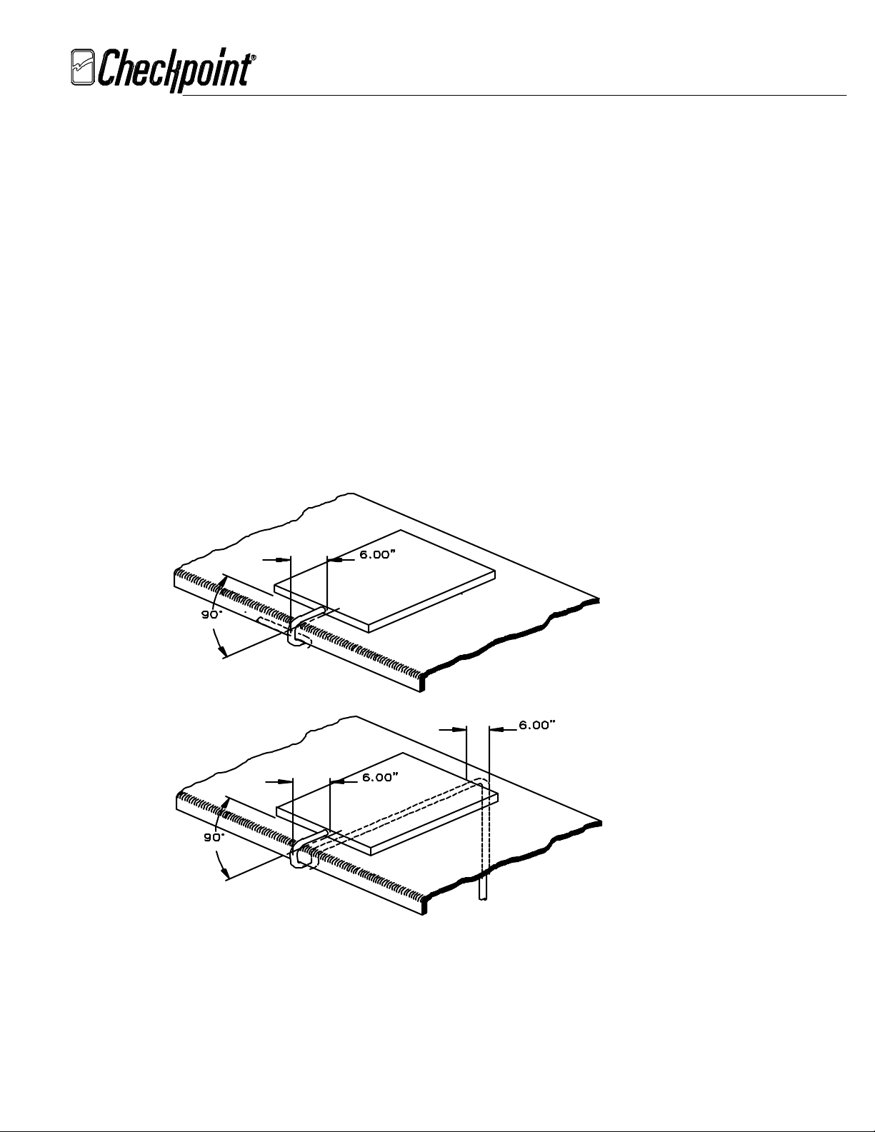
3.2.1 Pad Connection
March 9, 2000
FCC ID: D04CP1900
C/PT IX can drive one or two pads or scanner/deactivators. The cable length
for the pad is 8 feet.
(Don’t alter the cable length under any circumstance)
Place each pad in position on its counter. The maximum distance between the
two pads that are connected to a single chassis is 12 feet. The best performance
can be achieved if the pad cable run straight out of the pad for at least 6”
(15 cm) before it changes direction. See Figure 3.2.1. If the direct pad-chassis
route takes the cable back under the pad, beneath the counter top, it’s best to
route the cable along the center of the pad. See Figure 3.2.1. Ensure that
deactivation remains as transparent to the checkout process as possible. Connect
the pads cables to either
drain wires to
GND
(pin 2 or 5 of J1) on the C/PT IX. See Figure 3.1 for the
ANT1
(pin 1,3 of J1) or
ANT2
(pin 4,6 of J1) with
detail.
Figure 3.2.1 Pad Connection
_____________________________________________________________________________________________________________________________________________
CHECKPOINT SYSTEMS, INC. CONFIDENTIAL AND PROPRIETARY INFORMATION, FOR INTERNAL USE ONLY.
DWG. 476736
PAGE 9
Page 10

Rev. 00
uttsplice
TECHNICAL DOCUMENTATION
INSTALLATION & TUNE-UP PROCEDURE
COUNTERPOINT IX
March 9, 2000
FCC ID: D04CP1900
3.2.2 Scanner Antenna Connection
To achieve optimized performance, the cable length from the chassis to 4_WAY
connector or buttsplice should be kept to 6 feet in length. (
length under any circumstance)
Extend the scanner antenna cable by 6 feet
Don’t alter this
using the 4-WAY connector or the buttsplice and the cable (Belden 8760 #18)
provided with the installation kit. See Figure 3.2.2. Connect the antenna cable
to either
GND
ANT1
(pin 1,3 of J1) or
(pin 2 or 5 of J1) on C/PT IX. See Figure 3.1 for the detail.
C/PT IX
ANT2
6 feet
(pin 4,6 of J1) with the drain wire to
Scanner
Connector
Or
B
Figure 3.2.2 Scanner Connection
3.3 Slaving Connection
Whether or not the C/PT IX should be slaved to other EAS systems or deactivation
systems depends on the environment of the site, the layout of the system, and the
settings of the system. Refer to Table 8.1 as a guideline for the minimum distances
required between the various EAS systems and the C/PT IX. If you are not sure,
temporarily plug in and turn on the C/PT IX, attach the oscilloscope probe to the
appropriate test point of the EAS systems receivers as you test for poor detection and
phantoms.
NOTE: The C/PT IX doesn’t have MASTER SLAVE OUTPUT.
It cannot be slaved to each other unless a master source such as
an EAS system or fiber master exists.
3.3.1 Wire Slaving
Connect the slaving input cable from the master source to
of J4). Connect the slaving output cable (daisy chain) to
of J4). Ground for wire slave is pin 2 of J4. See Figure 3.1 for the detail.
Slave In
Slave Out
(pin 5, 6
(pin 3,4
_____________________________________________________________________________________________________________________________________________
CHECKPOINT SYSTEMS, INC. CONFIDENTIAL AND PROPRIETARY INFORMATION, FOR INTERNAL USE ONLY.
DWG. 476736
PAGE 10
Page 11
Rev. 00
TECHNICAL DOCUMENTATION
INSTALLATION & TUNE-UP PROCEDURE
COUNTERPOINT IX
3.3.2 Fiber Slaving
3.3.3 Secure Cables
3.4 Interlock Connection
If the interlock function is used, connect the interlock input cable either directly from
the scanner or from the audio interlock board to
See Figure 3.1 for the detail.
March 9, 2000
FCC ID: D04CP1900
When fiber slaving, you need the fiber receiver found in Fiber Slave Kit
(P/N 469022). Plug the fiber receiver into U15 and tie wrap it. Connect the
fiber cable with the connector from the fiber master to the fiber receiver.
Secure slave/inhibit wiremold, measure, cut, and lay the cable. Secure the
pad- chassis and power cables to the sales counter surfaces with cable ties.
Use plastic wiremold where cables are visible to the store personnel. Secure
the excess of either cable under the counter by bundling it. Do not coil it.
Make sure to leave enough cable slack at the chassis end to allow service
access. Leave the chassis unplugged. Install Heyco bushings at each cable
entry on the rear of the deactivator chassis.
INTLK
at J4. Notice the polarity.
3.5 Optional Remote Unit Connection
When configured in IV and VI modes, an optional remote unit containing a sonalert
and the power
ON/OFF
switch can be connected to the C/PT IX chassis. The
purpose of this unit is to provide easy access to power
the remote unit, remove the wires from
off the exposed leads. Install the wires from the remote unit following Table 3.5.
Install Heyco Bushing at the entry of the cable. See Figure 3.1 for the detail.
Cable From the Remote Unit Connection to C/PT IX Chassis
Red, Brown and Yellow SWITC H Pin 4 at J2
Black and Green SWITCH Pin 3 at J2
White SPKR ( + ) at J3
Blue SPKR ( - ) at J3
Orange PWR ( - ) at J2
Table 3.5 Remote Unit Connection
SWITCH
( next t o SP K R )
( next t o PWR )
ON/OFF
switch. To connect
at J2 of the C/PT IX chassis and cut
_____________________________________________________________________________________________________________________________________________
CHECKPOINT SYSTEMS, INC. CONFIDENTIAL AND PROPRIETARY INFORMATION, FOR INTERNAL USE ONLY.
DWG. 476736
PAGE 11
Page 12

Rev. 00
TECHNICAL DOCUMENTATION
INSTALLATION & TUNE-UP PROCEDURE
COUNTERPOINT IX
4.0 Install the C/PT IX
4.1 Chassis Installation
The C/PT IX chassis can be installed vertically and horizontally. Ensure to install
the chassis at a convenient location where the customer has easy access to
switch. Unscrew and slide the cover out of the chassis, install the cover horizontally
as shown in Figure 4.1A and vertically as shown in Figure 4.1B, and slide the chassis
back on. Ensure to allow enough space so the chassis can slide in and out easily.
March 9, 2000
FCC ID: D04CP1900
ON/OFF
Figure 4.1A Horizontal Chassis Installation
_____________________________________________________________________________________________________________________________________________
CHECKPOINT SYSTEMS, INC. CONFIDENTIAL AND PROPRIETARY INFORMATION, FOR INTERNAL USE ONLY.
DWG. 476736
PAGE 12
Page 13

Rev. 00
TECHNICAL DOCUMENTATION
INSTALLATION & TUNE-UP PROCEDURE
COUNTERPOINT IX
March 9, 2000
FCC ID: D04CP1900
Figure 4.1B Vertical Chassis Installation
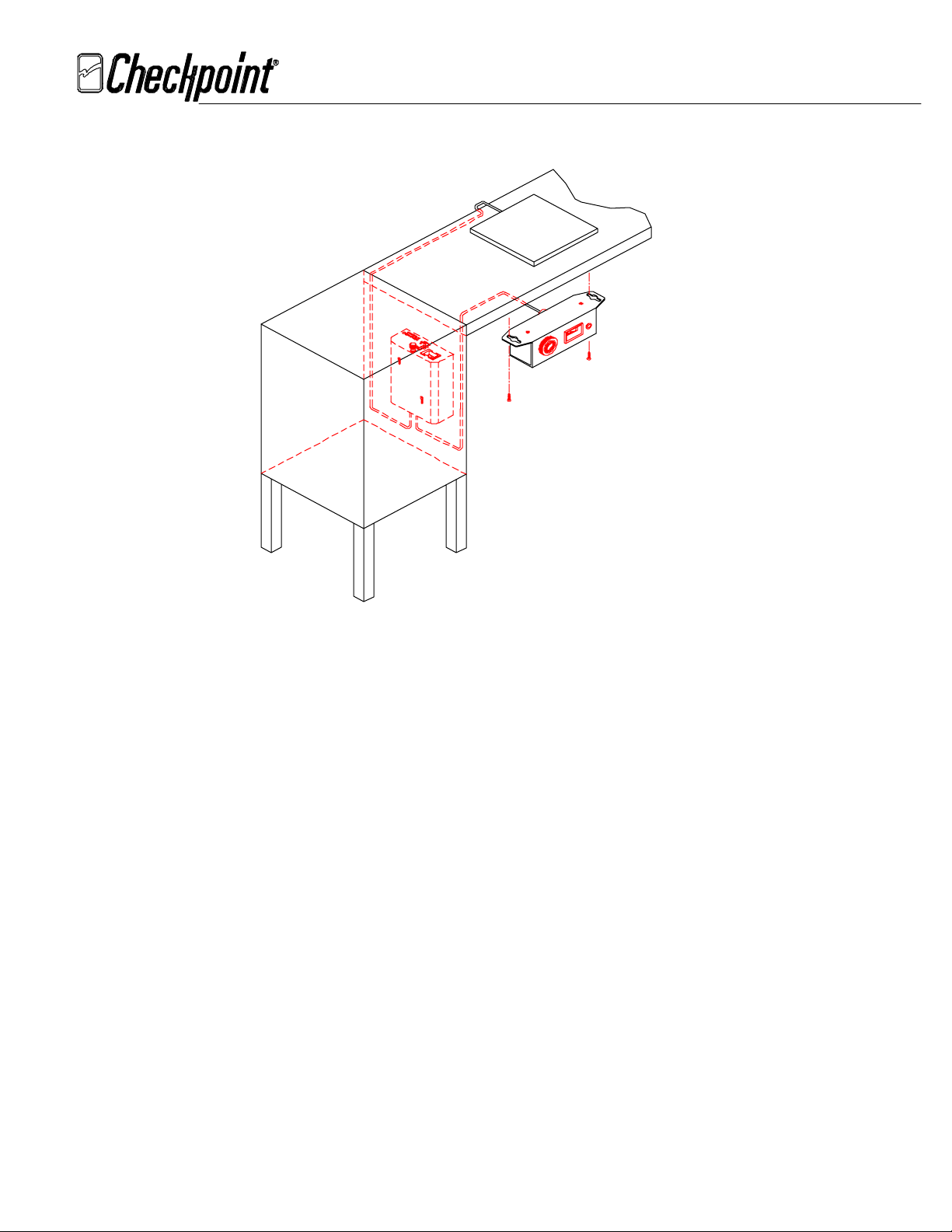
4.2 Remote Unit Installation
When a remote unit is used, it should be installed at a location where the customer has
easy access to the unit. Figure 4.2A and 4.2B show examples.
Figure 4.2A Vertical Remote Unit Installation
_____________________________________________________________________________________________________________________________________________
CHECKPOINT SYSTEMS, INC. CONFIDENTIAL AND PROPRIETARY INFORMATION, FOR INTERNAL USE ONLY.
DWG. 476736
PAGE 13
Page 14
Rev. 00
TECHNICAL DOCUMENTATION
INSTALLATION & TUNE-UP PROCEDURE
COUNTERPOINT IX
March 9, 2000
FCC ID: D04CP1900
5.0
Figure 4.2B Horizontal Remote Unit Installation
C/PT IX DIP Switch Configuration
The C/PT IX can be configured as master or slave unit, operating in IV, V, or VI modes. This
is done by the settings of SW1, SW2, SW3, SW4, and SW5.
In IV mode, the C/PT IX detects the tag first and switches from the low power mode to the
high power mode to destroy the tag.
In V mode, the C/PT IX operates in the high power mode all the time to destroy the tag and
will not detect the tag.
In VI mode, the C/PT IX operates in the high power mode all the time to destroy the tag but
will detect the hard tags and any missed soft tags.
Almost all the C/PT IX’s functions are configured by three banks of DIP switches. Refer to
Table 8.3 for a complete listing of the DIP switches and their functions. A simplified table
can also be found on the back of the chassis.
5.1 Antenna Matching
_____________________________________________________________________________________________________________________________________________
CHECKPOINT SYSTEMS, INC. CONFIDENTIAL AND PROPRIETARY INFORMATION, FOR INTERNAL USE ONLY.
DWG. 476736
PAGE 14
Page 15

Rev. 00
TECHNICAL DOCUMENTATION
INSTALLATION & TUNE-UP PROCEDURE
COUNTERPOINT IX
To achieve optimized performance, the C/PT IX’s output impedance needs to be matched
Note 1: The cable length is 8 feet for the pads and 6 feet for the scanners.
Note 2: The table is for single pad or scanner. If double, refer to Section 8.0 for details.
SCANNERS SW1,2 (1) SW1,2 (2) SW1,2 (3) SW1,2 (4) SW1,2 (5) SW1,2 (6)
HS1250
LS5000
LS5700
LS9100
MAGELLAN
MAGELLAN SL
NCR7820
NCR7824
NCR7870
NCR7875
ORION
PADS
SP750F
SP760SLS
SP960LS
VS1000
VS1000S
WAND
March 9, 2000
FCC ID: D04CP1900
to the scanner antenna or the pad it connects to. This is done by using DIP switches SW1
and SW2.
Table 5.1 applies to CP IV, V, or VI mode
.
ON OFF OFF OFF ON OFF
OFF OFF ON OFF OFF OFF
ON OFF OFF OFF OFF OFF
OFF OFF ON OFF OFF OFF
OFF OFF ON OFF OFF OFF
ON OFF OFF OFF OFF OFF
ON OFF OFF OFF ON OFF
ON OFF OFF OFF ON OFF
ON OFF OFF OFF OFF OFF
OFF OFF OFF OFF OFF ON
OFF OFF OFF OFF ON OFF
ON OFF OFF OFF OFF OFF
ON OFF OFF OFF ON OFF
ON OFF ON OFF OFF ON
ON OFF ON OFF OFF OFF
ON OFF ON OFF OFF OFF
ON OFF OFF OFF OFF OFF
OFF OFF OFF OFF OFF OFF
Table 5.1 Antenna Matching Chart
_____________________________________________________________________________________________________________________________________________
CHECKPOINT SYSTEMS, INC. CONFIDENTIAL AND PROPRIETARY INFORMATION, FOR INTERNAL USE ONLY.
DWG. 476736
PAGE 15
Page 16

Rev. 00
TECHNICAL DOCUMENTATION
INSTALLATION & TUNE-UP PROCEDURE
COUNTERPOINT IX
5.2 IV Mode
When configured as IV mode, SW1, SW2, SW3, SW4, and SW5 need to be set
as follows:
SW1,2 DESCRIPTION
1,2 See Table 5.1
3,4 See Table 5.1
5,6 See Table 5.1
SW3
1 OFF See Note 3
2 OFF See Note 4 Note 4: This is for interlock function. See Table 8.3.
3 OFF See Note 4
4 OFF See Note 6 Note 6: This is a default setting for MASTER mode, see Table 8.3 for
5 OFF See Note 6
6 OFF See Note 6
March 9, 2000
FCC ID: D04CP1900
slaving
SW4
1OFF
2OFF
3ON
4OFF
5 ON See Note 7 Note 7: This is a default setting for MEDIUM detection, see Table 8.3
6 OFF See Note 7
for different settings.
SW5
1 OFF See Table 8.3
2 OFF See Note 8 Note 8: This is the default freq. band (7.6 – 8.7 MHz), see Table 8.3
3 OFF See Note 8
for different bands.
4 OFF See Note 8
Note 3: This is a default setting for Medium deactivation. ( 44 VDC at VPA TP2 for FCC, CE/UK
compliance ) For non- regulated market, please see Table 8.3 for the settings.
Table 5.2 Settings for IV Mode
_____________________________________________________________________________________________________________________________________________
CHECKPOINT SYSTEMS, INC. CONFIDENTIAL AND PROPRIETARY INFORMATION, FOR INTERNAL USE ONLY.
DWG. 476736
PAGE 16
Page 17

Rev. 00
TECHNICAL DOCUMENTATION
INSTALLATION & TUNE-UP PROCEDURE
COUNTERPOINT IX
5.3 V Mode
When configured as V mode, SW1, SW2, SW3, SW4, and SW5 need to be set
as follows:
SW1,2 DESCRIPTION
1,2 See Table 5.1
3,4 See Table 5.1
5,6 See Table 5.1
SW3
1 OFF See Note 9
2 OFF See Note 10 Note 10: This is for interlock function in IV mode
3 OFF See Note 10
4 OFF See Note 11 Note 11: This is a default setting for MASTER mode, see Table 8.3 for
5 OFF See Note 11
6 OFF See Note 11
March 9, 2000
FCC ID: D04CP1900
slaving
SW4
1OFF
2OFF
3OFF
4OFF
5 N/A See Note 12 Note 12: Not used in V mode.
6 N/A See Note 12
SW5
1 OFF See Table 8.3
2 OFF See Note 13 Note 13: This is a default setting for MASTER mode, see Table 8.3
3 OFF See Note 13
for slaving
4 OFF See Note 13
Note 9: This is a default setting for Medium deactivation ( 44 VDC at VPA TP2 for FCC, CE/UK compliance )
For non- regulated market, please see Table 8.3 for the settings.
Table 5.3 Settings for V Mode
_____________________________________________________________________________________________________________________________________________
CHECKPOINT SYSTEMS, INC. CONFIDENTIAL AND PROPRIETARY INFORMATION, FOR INTERNAL USE ONLY.
DWG. 476736
PAGE 17
Page 18
Rev. 00
TECHNICAL DOCUMENTATION
INSTALLATION & TUNE-UP PROCEDURE
COUNTERPOINT IX
5.4 VI Mode
When configured as VI mode, SW1, SW2, SW3, SW4, and SW5 need to be set
as follows:
SW1,2 DESCRIPTION
1,2 See Table 5.1
3,4 See Table 5.1
5,6 See Table 5.1
SW3
1 OFF See Note 14
2 OFF See Note 15 Note 15: This is for interlock function. See Table 8.3.
3 OFF See Note 15
4 OFF See Note 16 Note 16: This is a default setting for MASTER mode, see Table 8.3 for
5 OFF See Note 16
6 OFF See Note 16
March 9, 2000
FCC ID: D04CP1900
slaving
SW4
1 ON Note 18: This is for interlock function. See Table 8.3 for settings.
2OFF
3N/A
4ON
5 ON See Note 19 Note 19: This is a default setting for MEDIUM detection, see Table 8.3
6 OFF See Note 19
for different settings.
SW5
1 OFF See Table 8.3
2 OFF See Note 20 Note 20: This is the default freq. band (7.6 – 8.7 MHz), see Table 8.3
3 OFF See Note 20
for different bands.
4 OFF See Note 20
Note 14: This is a default setting for Medium deactivation. ( 44 VDC at VPA TP2 for FCC, CE/UK compliance )
For non- regulated market, please see Table 8.3 for the settings
Table 5.4 Settings for VI Mode
_____________________________________________________________________________________________________________________________________________
CHECKPOINT SYSTEMS, INC. CONFIDENTIAL AND PROPRIETARY INFORMATION, FOR INTERNAL USE ONLY.
DWG. 476736
PAGE 18
Page 19

Rev. 00
TECHNICAL DOCUMENTATION
INSTALLATION & TUNE-UP PROCEDURE
COUNTERPOINT IX
6.0
C/PT IX Tune Up and Test Procedure
If you haven’t already done so, follow the standard procedure to tune the sensing system to
Checkpoint’s specifications
6.1 Center Frequency and Deviation Verify
Since the C/PT IX uses pulse-listen technology, it’s difficult to measure the center
frequency and the deviation using regular tools. Also, since the C/PT IX uses DDS
(Direct Digital Synthesis), the frequency band can not be adjusted. Use dip meter and
the ear phone to verify the center frequency and the deviation. You should
hear the clicking sound with your earphone from 7.6 –8.7 MHz when you sweep the
frequency using the dip meter. See Figure 8.1.
6.2
IV Mode
Follow step 5.2 to configure the chassis
March 9, 2000
FCC ID: D04CP1900
BEFORE
tuning the deactivators.
Detection Field Adjustment
When in IV mode, the detection field should be adjusted properly to achieve
the best performance.
6.3 V Mode
Follow step 5.3 to configure the chassis. Test the deactivation height using live 410
tags. The deactivation height should be comparable to the numbers listed in Table
8.2. If the deactivation height is worse than expected, go to Appendix A for the
detailed tuning.
To insure that tags will be detected before they are deactivated adjust R11 to
its minimum setting which is approximately 0.7 VDC. See Figure 8.1.
Sensitivity adjustment
When in IV mode, the sensitivity of the receiver should be adjusted properly
to achieve the best performance.
Adjust GAIN (R4) all the way clockwise (maximum) to achieve better
detection. If phantoms occur, adjust GAIN (R4) counterclockwise slightly
until the phantoms stop.
Test the detection height using standard 410 test tag. The detection height
should be comparable to the numbers listed in Table 8.2. If the detection
height is less than expected, go to Appendix A for the detailed tuning.
_____________________________________________________________________________________________________________________________________________
CHECKPOINT SYSTEMS, INC. CONFIDENTIAL AND PROPRIETARY INFORMATION, FOR INTERNAL USE ONLY.
DWG. 476736
PAGE 19
Page 20

Rev. 00
TECHNICAL DOCUMENTATION
INSTALLATION & TUNE-UP PROCEDURE
COUNTERPOINT IX
6.4 VI Mode
Follow step 5.4 to configure the chassis. Test the deactivation height using live 410
tags. The deactivation height should be same or better compared to the numbers
listed in Table 8.2. If the deactivation height is worse than expected, go to Appendix
A for the detailed tuning. Test the detection height using standard 410 test tag, it
should be at least 6” or higher if a pad is used.
6.5 Interlock Turn-On Time Adjustment
When the interlock function is used, adjust INT TIME (R98) clockwise to increase
the interlock Turn-On time from 0.2 - 10 seconds in LO mode (SW3-3 OFF) and 1min
– 10 min in HI mode (SW3-3 ON). See Figure 8.1.
7.0
After The Installation
Wait until after installation and tuning to show the customer personnel how the deactivator
operates. Ensure that site management is present and let them designate which site
employees will attend. If you have just installed a sensing system and deactivators, explain
the sensing system operation first, then follow with the deactivator operations, as follows:
March 9, 2000
FCC ID: D04CP1900
7.1 Turning the Deactivator On and Off
The deactivator should be turned off when not in use to prevent unauthorized
personnel from deactivating tags.
Show the operation of the power switch, and point out the green light on the chassis,
which shows that the power is on. If the sensing system control module is Model N or
later, mention that a key is required to activate the system. If the sensing system is
the master in a slaved configuration, indicate that it must be on before the
deactivators will function.
7.2
How the Deactivator Works
Show how the deactivator operation is similar to the sensing system in that both
systems transmit radio signals which cause tags to respond with their own radio
signals when they come into range. Explain that each system's receiver recognizes the
tag signal then verifies it. Then explain that the difference between the two is what
each does with the verified tag signal. The sensing system alarms loudly upon tag
verification. The deactivator alarms softly at the chassis and disables the tag. When
deactivation is immediate, there will be no audible alarm.
7.3 When the Tag Doesn't Deactivate
Explain that tags vary in length of time required to deactivate. Some tags deactivate
instantly, while others take longer. It may be that a very few wouldn't deactivate
automatically. If this should occur, just place a Thank You label over the tag.
Mention that any hard tags, hang tags, or non-deactivatable stickers also will not
deactivate automatically. Clerks must either remove these tags, or mask them with a
_____________________________________________________________________________________________________________________________________________
CHECKPOINT SYSTEMS, INC. CONFIDENTIAL AND PROPRIETARY INFORMATION, FOR INTERNAL USE ONLY.
DWG. 476736
PAGE 20
Page 21

Rev. 00
TECHNICAL DOCUMENTATION
INSTALLATION & TUNE-UP PROCEDURE
COUNTERPOINT IX
Thank You label. For these tags, the deactivator acts as a point of sale detector. It
continues to alarm softly until the tag is removed or masked.
7.4 When the Sensing System Alarms
Employees should follow their management's standard procedure for handling sensing
system alarms, just as if there were no deactivators in the store. If there is no
standard procedure, make a mental note to encourage management to set one. Wait
until after you conclude the training meeting to avoid embarrassing management in
front of the employees.
7.5 Testing the Deactivator
Employees should turn on the deactivator before use and turn off the deactivator
when unattended. An employee verifies power by viewing the green light on the
chassis. Beyond checking the power on switch, there isn't much need to test the
deactivator's function because it will be immediately apparent should a unit fail to
disable tags.
Show employees how to test for deactivation in case site management should want to
test a unit. In IV and VI modes, use a hard tag, hang tag or non-deactivatable sticker.
Hold it about 18" (46 cm) above each deactivator pad and bring it down slowly to the
pad's surface. Point out alarm occurs at about 10.5" (27 cm) height. Take a
deactivatable sticker and move it down in the same manner. Observe the signal stops
as the tag gets closer. Try to alarm the deactivator again with the same tag to verify
that it has been disabled. Make sure that this activity doesn't alarm any other
deactivator or sensing system. In V mode, use DV1000 and live 410 tags to test the
system.
March 9, 2000
FCC ID: D04CP1900
7.6 Operational Problems
Give site management the telephone numbers used for calling Checkpoint service
about equipment problems. Detail how to avoid potential problems by keeping
permanent tags and stickers and also metal objects away from the deactivator pads.
7.7 Tagging
Show how deactivatable stickers can now be hidden in protected merchandise.
Remind the customer that metal and foil objects usually can't be protected by pressure
sensitive tags. Detail that all procedures for tagging merchandise covered in the
User's Guide apply also to deactivatable tags. Detail the necessity of maintaining a
tagging system, use of merchandise value or theft activity to decide which
merchandise to tag, and the need for following an established procedure when the
sensing system alarms.
8.0 Figures and Tables
_____________________________________________________________________________________________________________________________________________
CHECKPOINT SYSTEMS, INC. CONFIDENTIAL AND PROPRIETARY INFORMATION, FOR INTERNAL USE ONLY.
DWG. 476736
PAGE 21
Page 22

Rev. 00
TECHNICAL DOCUMENTATION
INSTALLATION & TUNE-UP PROCEDURE
COUNTERPOINT IX
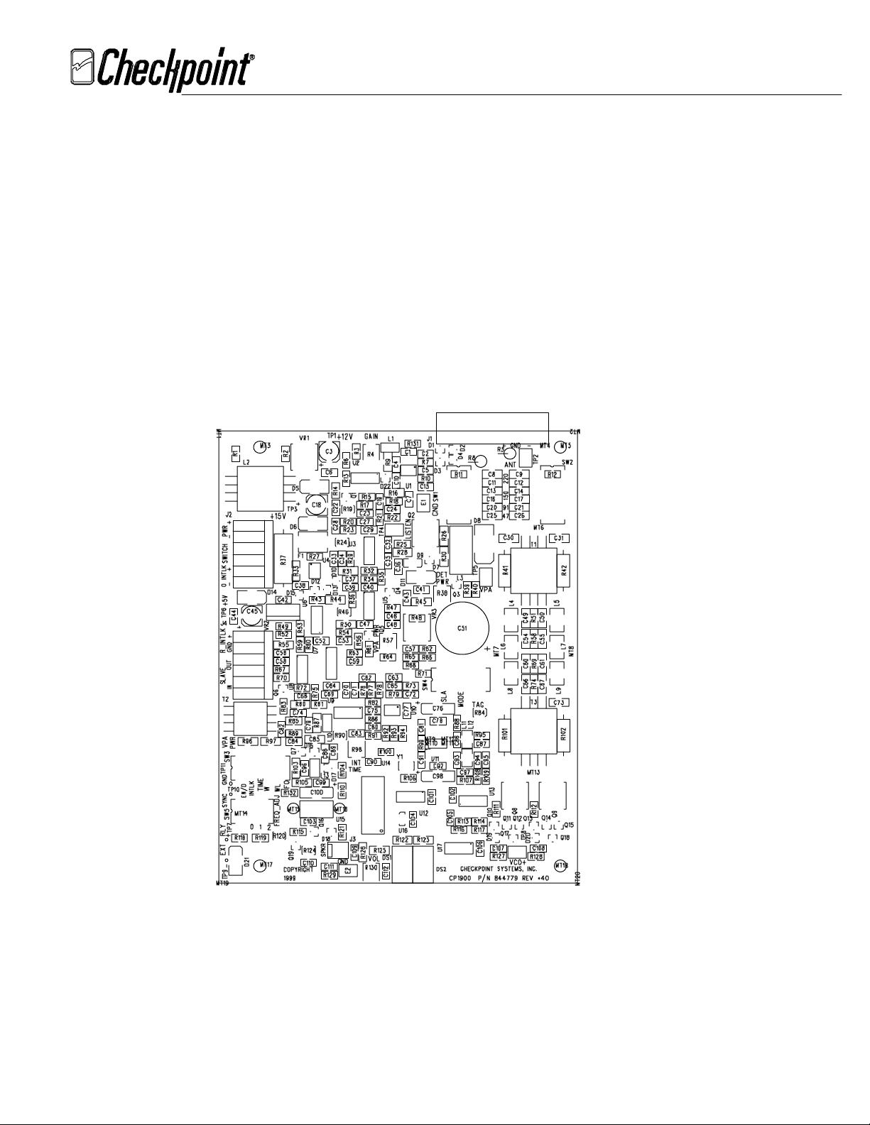
8.1
Test Points and Adjustments
RX GAIN
Potentiometer
March 9, 2000
FCC ID: D04CP1900
Antenna TP
Listen TP
VPA TP
Detection Power
Adjustment (4mode)
Deactivation Power
Adjustment
Sounder Volume
Figure 8.1 Test Points and Adjustment
Interlock TP
Interlock Time
Adjustment
Potentiometer
_____________________________________________________________________________________________________________________________________________
CHECKPOINT SYSTEMS, INC. CONFIDENTIAL AND PROPRIETARY INFORMATION, FOR INTERNAL USE ONLY.
DWG. 476736
PAGE 22
Page 23

Rev. 00
TECHNICAL DOCUMENTATION
INSTALLATION & TUNE-UP PROCEDURE
COUNTERPOINT IX
8.2 Slaving Decision Chart/All testing have been done with pads.
System C/PT IX
Power
Hi 15 ft 35 ft 20 ft 50 ft 20 ft 50 ft
Condor Med 15 ft 30 ft 20 ft 40 ft 20 ft 40 ft
Low 15 ft 20 ft 20 ft 35 ft 20 ft 35 ft
Hi 9 ft 9 ft 2 ft 4 ft 3 ft 4 ft
QS4000 Med 9 ft 9 ft 2 ft 3 ft 3 ft 3 ft
Low 9 ft 9 ft 2 ft 3 ft 3 ft 3 ft
Hi 8 ft 8 ft 2 ft 5 ft 2 ft 5 ft
QS2000 Med 8 ft 8 ft 2 ft 4 ft 2 ft 4 ft
Low 8 ft 8 ft 2 ft 3 ft 2 ft 3 ft
Hi 8 ft 8 ft 2 ft 5 ft 2 ft 5 ft
QuickSilver Med 8 ft 8 ft 2 ft 4 ft 2 ft 4 ft
Low 8 ft 8 ft 2 ft 3 ft 2 ft 3 ft
Hi 7 ft 7 ft 2 ft 5 ft 2 ft 5 ft
Inca Med 7 ft 7 ft 2 ft 4 ft 2 ft 4 ft
Low 7 ft 7 ft 2 ft 3 ft 2 ft 3 ft
Hi 7 ft 7 ft 13 ft 13 ft 13 ft 13 ft
CP IV Med 7 ft 7 ft 7 ft 7 ft 7 ft 7 ft
Low 7 ft 7 ft 4 ft 4 ft 4 ft 4 ft
CPV Hi 8 ft 8 ft 0 ft 0 ft 5 ft 5 ft
High Power Med 8 ft 8 ft 0 ft 0 ft 5 ft 5 ft
Low 8 ft 8 ft 0 ft 0 ft 5 ft 5 ft
Hi 18 ft 18 ft 1 ft 1 ft 6 ft 6 ft
CP VI Med 18 ft 18 ft 1 ft 1 ft 6 ft 6 ft
Low 18 ft 18 ft 1 ft 1 ft 6 ft 6 ft
C/PT IX in Hi 15 ft 15 ft 18 ft 18 ft 18 ft 18 ft
IV Mode Med 15 ft 15 ft 15 ft 15 ft 15 ft 15 ft
Low 15 ft 15 ft 14 ft 14 ft 14 ft 14 ft
C/PT IX in Hi 18 ft 18 ft 0 ft 0 ft 5 ft 5 ft
V Mode Med 15 ft 15 ft 0 ft 0 ft 3 ft 3 ft
Low 14 ft 14 ft 0 ft 0 ft 3 ft 3 ft
C/PT IX in Hi 18 ft 18 ft 5 ft 5 ft 5 ft 5 ft
VI Mode Med 15 ft 15 ft 3 ft 3 ft 3 ft 3 ft
Low 14 ft 14 ft 3 ft 3 ft 3 ft 3 ft
March 9, 2000
FCC ID: D04CP1900
C/PT IX Slaving Decision Chart
C/PT IX Operating Mode
IV V VI
Slaved Non-Slaved Slaved Non-Slaved Slaved Non-Slaved
Table 8.2 C/PT IX Slaving decision Chart
_____________________________________________________________________________________________________________________________________________
CHECKPOINT SYSTEMS, INC. CONFIDENTIAL AND PROPRIETARY INFORMATION, FOR INTERNAL USE ONLY.
DWG. 476736
PAGE 23
Page 24

Rev. 00
TECHNICAL DOCUMENTATION
INSTALLATION & TUNE-UP PROCEDURE
COUNTERPOINT IX
8.3 DIP Switch Settings
SW1,2 ON Position OFF Position
1,2 220 pF enabled 220 pF disabled Note: Use SW1 and SW2 to tune the antennas. Refer to Table 5.1
3,4 150 pF enabled 150 pF disabled and Appendix A for the details
5 91 pF enabled 91 pF disabled
6 47 pF enabled 47 pF disabled
SW3 ON Position OFF Position
1 ADJ. VPA (50–90V) 44V VPA Use R57 to adjust VPA
2 Interlock enabled Interlock disabled
3 HI (Intlk. Time) LO (Intlk. Time) LO (0.2 – 10 sec), HI (1- 10 min)
4 Wire slave ON Wire slave OFF If no slave source is used 4,5, and 6 should kept OFF.
5 Wireless slave ON Wireless slave OFF
6 Fiber slave ON Fiber slave OFF
SW4 123456
March 9, 2000
FCC ID: D04CP1900
Description
Description
Description
10Hz/ 16 pulse OFF OFF --- --- --- --- 10Hz is the average frequency when not slaved
164Hz/ single pulse ON OFF --- --- --- --- 164Hz is the average frequency when not slaved
Pulse Listen N/A ON --- --- --- --4 Mode --- --- ON OFF --- --5 Mode --- --- OFF OFF --- --6 Mode --- --- N/A ON --- --Fast Detection --- --- --- --- OFF OFF 2 tags in sequence
Medium Detection --- --- --- --- ON OFF 4 tags in sequence
Slow Detection --- --- --- --- N/A ON 16 tags in sequence
SW5 1 2 3 4
Disable Dual Band OFF --- --- --- This feature is used to enable a second frequency band. Dual Band
Enable Dual Band ON --- --- --- can’t be used in the US. The software disables Dual band in 5Mode.
7.6 - 8.7 MHz --- OFF OFF OFF This is the default setting for the US.
7.4 - 9.0 MHz --- ON OFF OFF
7.4 - 8.8 MHz --- OFF ON OFF This is the default setting for the Europe.
7.8 - 9.4 MHz --- ON ON OFF
7.8 - 9.8 MHz --- OFF OFF ON
7.5 - 8.6 MHz --- ON OFF ON
7.7 - 8.8 MHz --- OFF ON ON
8.5 - 9.8 MHz --- ON ON ON
Table 8.3 DIP Switch Settings
_____________________________________________________________________________________________________________________________________________
CHECKPOINT SYSTEMS, INC. CONFIDENTIAL AND PROPRIETARY INFORMATION, FOR INTERNAL USE ONLY.
DWG. 476736
PAGE 24
Page 25

Rev. 00
TECHNICAL DOCUMENTATION
INSTALLATION & TUNE-UP PROCEDURE
COUNTERPOINT IX
8.4
INTERLOCK Time Adjustment Chart
The chart below specifies the voltage on the INTLK TP (Figure 8.1) to set the INTERLOCK
time using INTERLOCK Adjustment potentiometer .
INTLK TP
(Vdc +/-0.2Vdc)
0.25 0.2 sec 1 min
0.75 1 sec 2 min
1.25 2 sec 3 min
1.75 3 sec 4 min
2.25 4 sec 5 min
2.75 5.5 sec 6 min
3.25 7 sec 7 min
3.75 8 sec 8 min
4.25 9 sec 9 min
4.75 10 sec 10 min
INTLK TIME LO
SW3-3 OFF
March 9, 2000
FCC ID: D04CP1900
INTLK TIME HI
SW3-3 ON
Table 8.4 INTERLOCK Time Adjustment Chart
_____________________________________________________________________________________________________________________________________________
CHECKPOINT SYSTEMS, INC. CONFIDENTIAL AND PROPRIETARY INFORMATION, FOR INTERNAL USE ONLY.
DWG. 476736
PAGE 25
Page 26

Rev. 00
TECHNICAL DOCUMENTATION
INSTALLATION & TUNE-UP PROCEDURE
COUNTERPOINT IX
8.5 Performance Matrix
SCANNER ANTENNA
MGR. NU MBER DETECTION DEACTIVATION
NCR
7820 231088 3" - 4" 7-1/2" - 9"
7824 231088 3" - 4" 7-1/2" - 9"
7870 EAS ready 8-1/2" - 10" 13" - 15"
7875 EAS ready 6" - 8" 11" - 13"
Symbol
LS5000-V 994026 6" - 8" 16" - 19"
LS5700 EAS ready 6" - 7" 13" - 15"
LS9100 076635 3" - 4" 4" - 5"
Spectra-Physics
MAGELLAN 098409 4-1/2" - 6" 10" - 12"
MAGELLAN SL EAS ready 4" - 6" 6" - 8"
VS1000 EAS ready 4-1/2" - 5-1/2" 8" - 10"
VS1000-Shroud 881777 6" - 8" 14" - 18"
HS1250 EAS ready 3-1/2" - 4" 6" - 8"
750F 231088 3-1/2" - 4-1/2" 8" - 9-1/2"
760SLS-M 881367 8" - 9" 15" - 18"
960LS 984483 4" - 5" 9" - 11-1/2"
ICL
ORION 431727 9" - 10-1/2" 14" - 17"
MISC.
CP WAND 076658 4-1/2" - 5-1/2" 5-1/2" - 6-1/2"
12 X 12 PAD 251281 8-1/2" - 9-1/2" 25" - 27"
LOW PROFILE 256279 7" - 8" 20" - 22"
March 9, 2000
FCC ID: D04CP1900
C/PT IX - 4 Mode C/PT IX - 5/6 Mode
V ---- Vertical H ---- Horizontal P ---- Plastic M ---- Metal W ---- Weigh Scale
Table 8.5 Performance Matrix
_____________________________________________________________________________________________________________________________________________
CHECKPOINT SYSTEMS, INC. CONFIDENTIAL AND PROPRIETARY INFORMATION, FOR INTERNAL USE ONLY.
DWG. 476736
PAGE 26
Page 27

Rev. 00
TECHNICAL DOCUMENTATION
INSTALLATION & TUNE-UP PROCEDURE
COUNTERPOINT IX
Appendix A Fine Tuning
DIP switch settings in Table 5.1 and Performance Matrix in Table 8.4 are based on the tests
performed in the lab under following conditions:
1. Use of 6 feet, #18 cables for the scanners
2. Use of 8 feet, #18 cables for the pads
3 Free of any interfering RF systems in an open environment
4. Use of standard 410 test tag in V mode testing
5. Use of standard 410 tags in IV mode testing
In actual installation, these settings may be changed for proper performance of the C/PT IX due to
environmental variations. If you are not able to tune the C/PT IX following the normal tuning
procedure detailed in previous chapters, refer to this chapter for fine tunings.
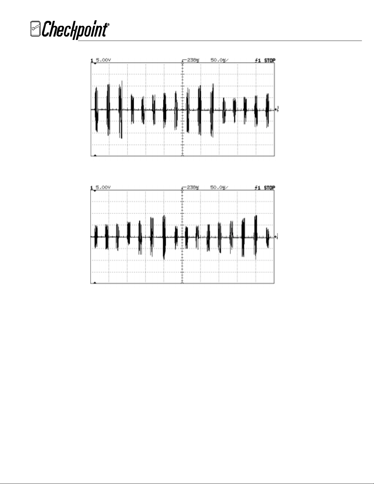
A.1 Detailed Tuning in IV Mode
To fine tune the C/PT IX in IV mode, change switches SW1 and SW2 so that the average
amplitude of the AC signal at ANT (TP2) is both maximized and as flat as possible. Start
with SW1 and SW2 all off and turn on the DIP switches two at a time beginning at position
(1). The following is an example of tuning 12 x 12 pad.
March 9, 2000
FCC ID: D04CP1900
Scope Settings:
Ch1: Voltage: 5.00v/div Triggered on Ch1
Time: 50us/div
Test point: TP1
Maximized Intensity
A1.1 AC Signal at ANT (TP2) with SW1, 2 ( 1 ) On
_____________________________________________________________________________________________________________________________________________
CHECKPOINT SYSTEMS, INC. CONFIDENTIAL AND PROPRIETARY INFORMATION, FOR INTERNAL USE ONLY.
DWG. 476736
PAGE 27
Page 28
Rev. 00
TECHNICAL DOCUMENTATION
INSTALLATION & TUNE-UP PROCEDURE
COUNTERPOINT IX
March 9, 2000
FCC ID: D04CP1900
A1.2 AC Signal at ANT (TP2) with SW1, 2 ( 5,6 ) On
A1.3 AC Signal at ANT (TP2) with SW1, 2 ( 3,4,5,6 ) On
From A1.1 to A1.3 it's clear that SW1 and SW2 position (1) should be set to on (A1.1) for
12x12 pad because the average amplitude of the AC signal at ANT (TP2) is highest
and more flat compared to the others.
_____________________________________________________________________________________________________________________________________________
CHECKPOINT SYSTEMS, INC. CONFIDENTIAL AND PROPRIETARY INFORMATION, FOR INTERNAL USE ONLY.
DWG. 476736
PAGE 28
Page 29

Rev. 00
TECHNICAL DOCUMENTATION
INSTALLATION & TUNE-UP PROCEDURE
COUNTERPOINT IX
If the C/PT IX phantoms, check the sensitivity as follows:
Scope Settings:
Ch1: Voltage: 100mv/div Triggered on Ch1
Time: 200us/div
Test point: LISTEN (TP4)
Maximized Intensity
Ensure the peak amplitude of the AC signal without the tag at LISTEN (TP4) is below 0.5Vp-p as
shown in A1.4.
March 9, 2000
FCC ID: D04CP1900
A1.4 AC Signal at LISTEN (TP4)
Readjust SW1 and SW2 if the signal at LISTEN (TP4) is over 0.5Vp-p.
A.2 Detailed Tuning in V Mode
Follow step A.1 to fine tune SW1 and SW2 without checking sensitivity.
A.3 Detailed Tuning in VI Mode
Follow step A.1 to fine tune the C/PT IX in VI mode for deactivation. If phantoms occur, reduce
the sensitivity by adjusting GAIN (R4) counterclockwise all the way.
_____________________________________________________________________________________________________________________________________________
CHECKPOINT SYSTEMS, INC. CONFIDENTIAL AND PROPRIETARY INFORMATION, FOR INTERNAL USE ONLY.
DWG. 476736
PAGE 29
 Loading...