

Page 1

Microcontroller-Café Checkpoint LAB
USB-RS232 CONVERTER
User’s Guide
© Checkpoint LAB 2011
Page 2
Microcontroller-Café Checkpoint LAB
TABLE OF CONTENT S
1. INTRODUCTION………………………………………………………………3
2. DEVICE OVERVIEW AND FEATURES..........................................................3
3. SYSTEM REQUIREMENTS...............................................................................4
4. INSTALLATION………………………………………………………………..4
4.1 Hardware interface…..……………...………..………………...………..4
4.2 Virtual COM port driver installation..………..………………...………..4
4.3 Virtual COM port driver installation check...…………………………...7
5. PORT CONFIGURATION…………………………………...............................8
APPENDIX………………………………………………………………………...9
© Checkpoint LAB 2011
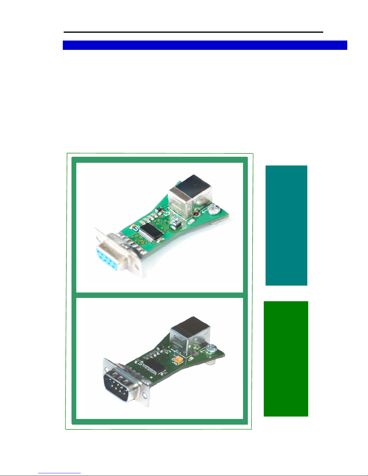
F – TYPE
M – TYPE .
2
Page 3
Microcontroller-Café Checkpoint LAB
1. INTRODUCTION
The USB to Serial converter making the use of legacy peripherals and communication between
PC and RS-232 devices easily. It’s simple low cost-effective solution ideal for various communication
and automation applications. Full compliance with USB specification 1.1 and compatible with USB
v2.0 ports. Supports the standard RS-232 Serial (com) interface and automatic handshaking mode. The
USB to Serial converter connects RS-232 serial devices to your USB providing a bridge connection
with a DB-9 female serial port connector on the end and USB port plug connector on the other side.
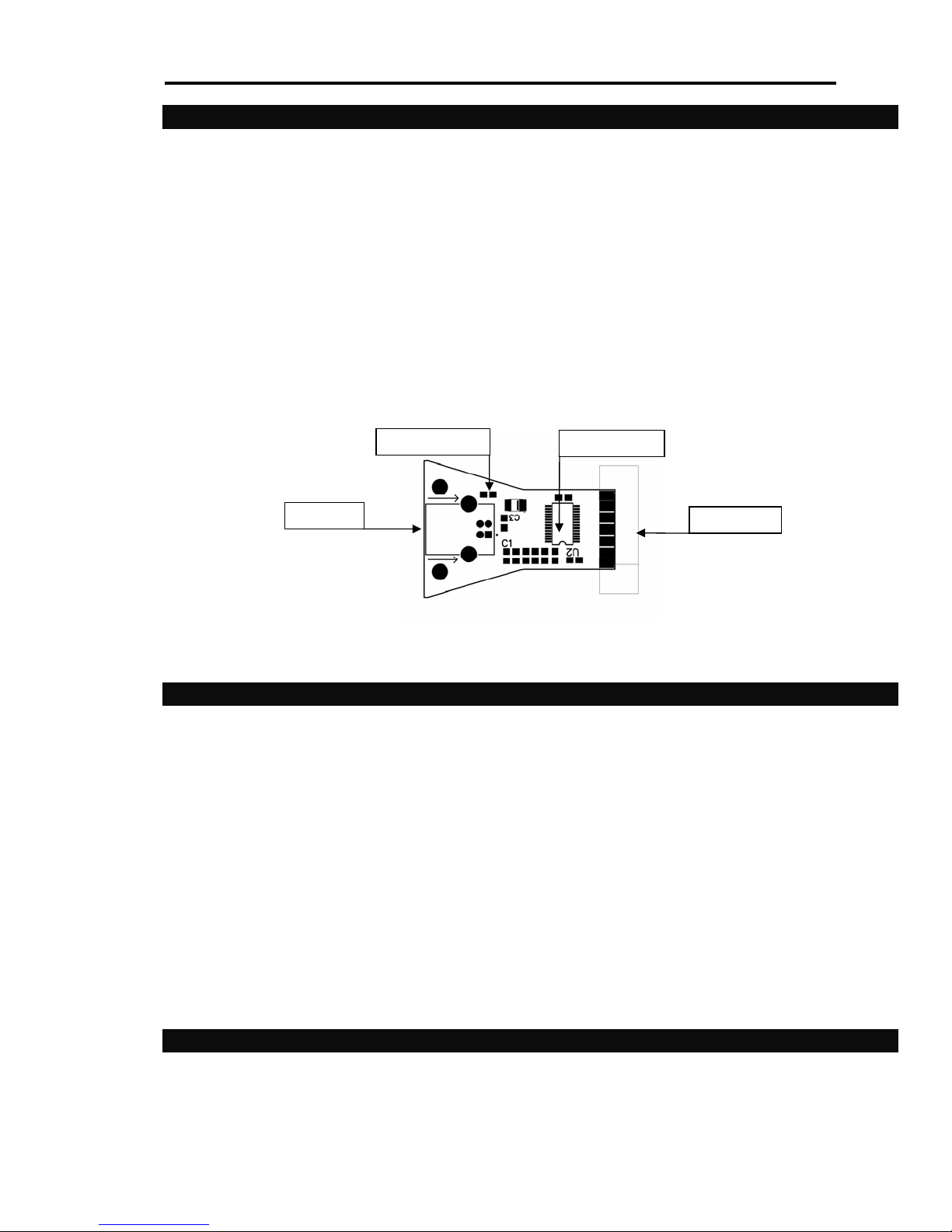
The USB-RS232 converter board components:
- “READY” device ready LED
- USB port connector
- DB 9 female serial port connector
“READY” LED
RS232 driver
USB port
RS232 port
Figure 1. USB - RS232 board layout
2. DEVICE OVERVIEW AND FEATURES
The USB-RS232 converter interface consists of the Tx (transmit), Rx (receive) data signals and
the RTS, CTS, DSR, DTR, DCD, RI control signals. The UART supports RTS/CTS, DSR/DTR, and XOn/X-Off handshaking. If the Virtual COM Port drivers are used, the data format and baud rate are set
during serial port configuration on the PC.
576 Byte receive buffer, 640 byte transmit buffer
Data bits: 5, 6, 7, 8
Stop bits: 1, 1.5* 2
Parity types: None, Even, Odd, Mark, Space
Baud rates: 9600, 14400, 19200, 38400, 56000, 115200 ( 7 / 8 data bits)
* - 5 data bits only
3. SYSTEM REQUIREMENTS
IBM Compatible Desktop/Laptop PC with free USB port
8X speed CD/DVD ROM
RAM - 32 Mb or higher
© Checkpoint LAB 2011
3
Page 4
Microcontroller-Café Checkpoint LAB
4 MB free disk space
Display : color SVGA display
Power supply : no external power supply required (powered from USB)
Operating system : Windows 2000/Windows XP/Windows Vista/Windows 7
4. INSTALLATION
This section will guide you through the Virtual COM port driver installation process and help to verify
installation process step by step.
4.1. Hardware interface
Please, follow the step-by-step installation procedure listed below:
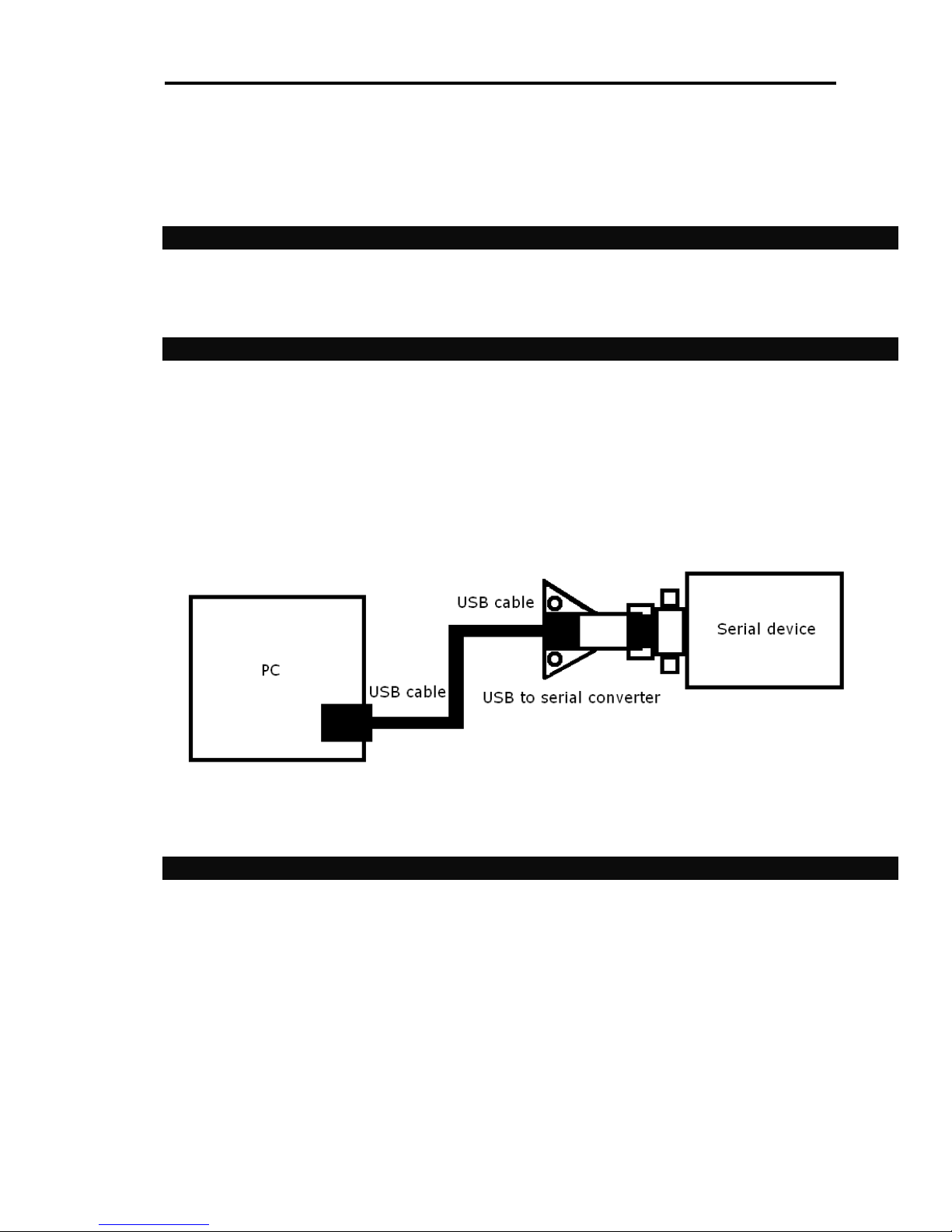
Hardware interface:
1. Connect one end of the USB cable to a USB port on the PC
2. Connect the other end of the USB cable to the USB connector on the USB-RS232 converter
3. Connect the DB-9 connector to the target serial device
4.2. Virtual COM port driver installation
1. Turn On your PC. Wait until “READY” led become red, from now device ready to use
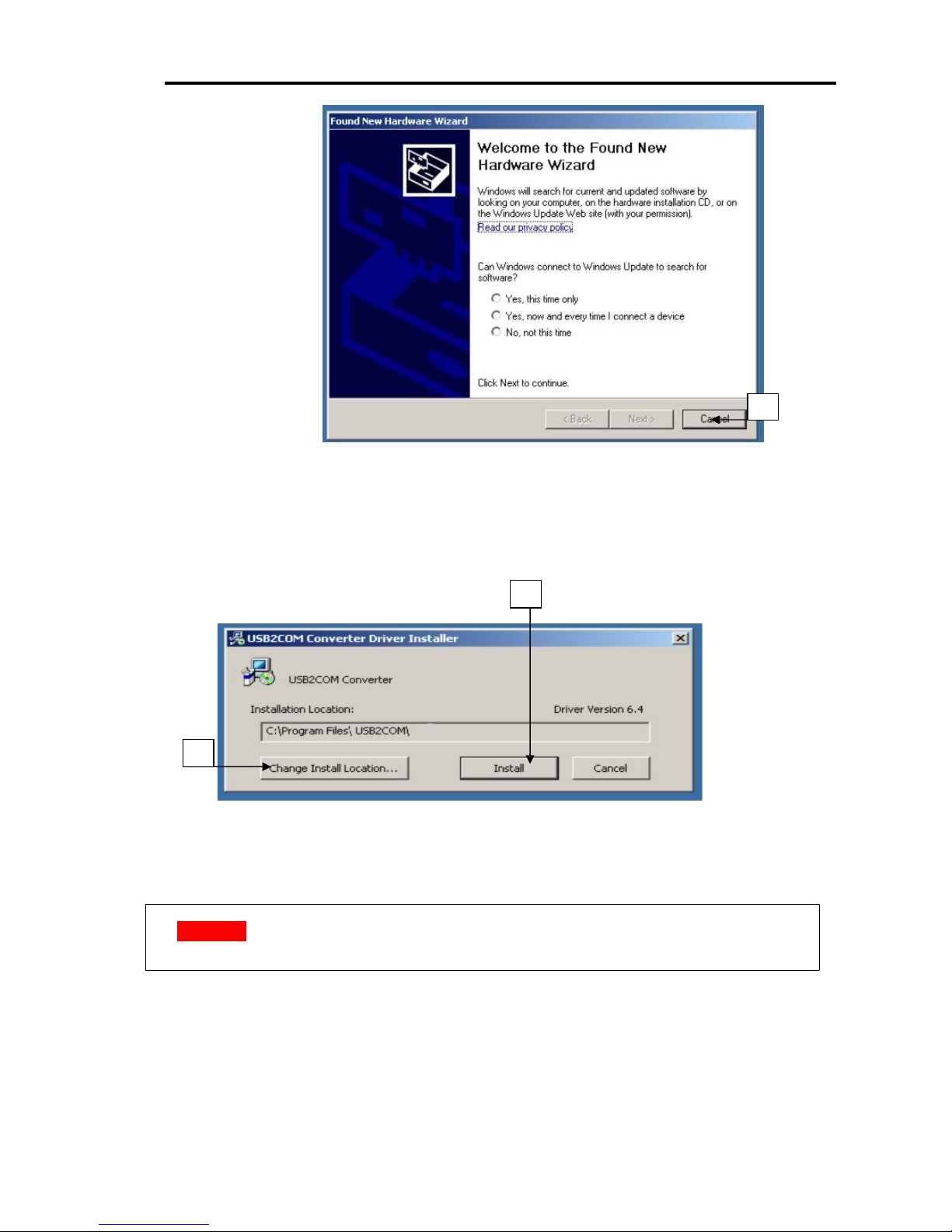
2. Then you should see window “Found New Hardware Wizard” on your Desktop
(Figure 3)
© Checkpoint LAB 2011
Figure 2. Hardware setup
4
Page 5
Microcontroller-Café Checkpoint LAB
3
Figure 3. “Found New Hardware Wizard” dialog
3. Click “Cancel”
4. Insert CD labeled: “USB SERIAL VCP DRIVER SETUP” into your CD/DVD drive
5. Run “USB2COM_DriverSetup.exe”
6. Follow to the wizard**
9
7
Figure 4. Driver installer dialog
**NOTE: User can continue installation into default folder path (for this case skip steps
6-8), or can change location in case of necessary
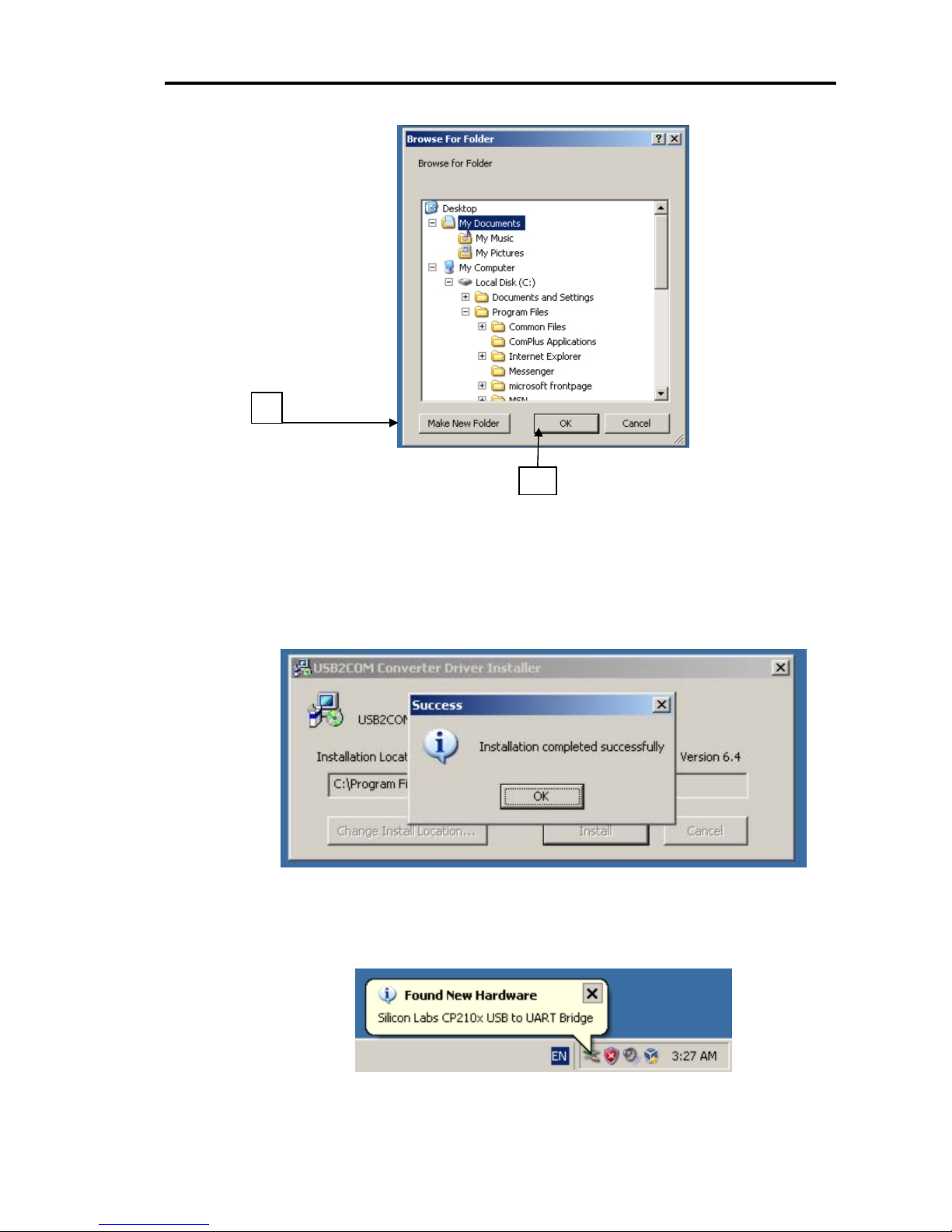
7. Click “Change Install Location…” button
8. Select new installati on directory among exiting directories under your hard drive or create new
by clicking “Make New Folder” button
9. Or click “Install” button to continue default driver installation
© Checkpoint LAB 2011
5
Page 6
Microcontroller-Café Checkpoint LAB
8
10
Figure 5. “Browse For Folder” dialog
10. Click “OK”
11. Once installation procedure is successfully completed you should see message window:
“Installation completed successfully” (Figure 6). Click “OK” and
“USB2COM Converter Driver Installer” will be automatically closed
12. After finish steps you’ll see “pop-up bubble” message of the Task bar (Figure 7)
© Checkpoint LAB 2011
Figure 6. Installation completed
Figure 7. Found New Hardware system message
6
Page 7
Microcontroller-Café Checkpoint LAB
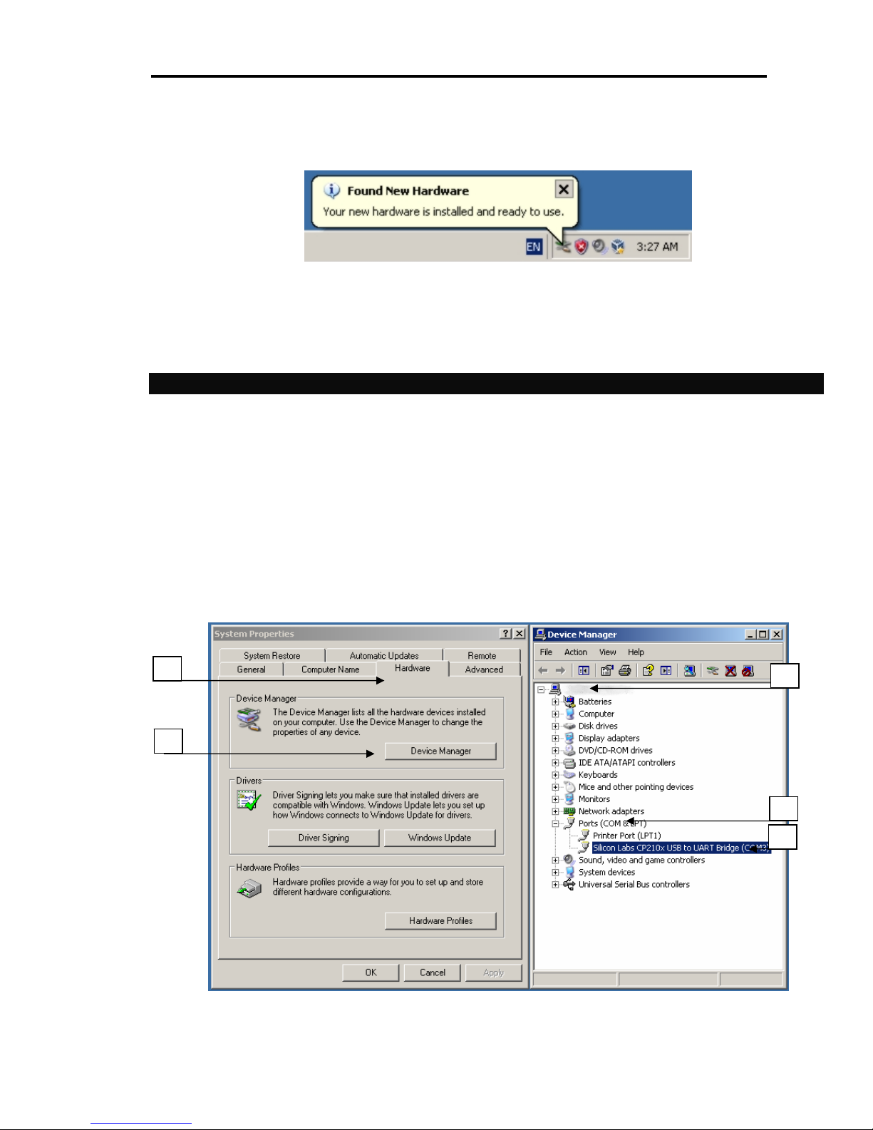
Be patient for few seconds until new one “pop-up bubble” confirmation message will appear:
Figure 8. New hardware is ready to use
Congratulations! Virtual COM Port Driver is ready to use with USB-RS232 converter.
Please make current installation clear for yourself and verify it
4.3 Virtual COM port driver installation check
Follow to the verification steps:
1. Click “My computer” icon on your Desktop or click menu “Start” -> select “Properties” from
pop-up menu
2. Select “Hardware” tab of “System properties” dialog
3. Click “Device manager” button
4. Expand tree of “Device manager”
5. Expand branch named “Ports (COM & LPT)”
6. In case of successful installation you’ll see node named “Silicon Labs CP210x USB to UART
Bridge (COM3)” ***
2
3
Figure 9. Virtual COM port in Device Manager
© Checkpoint LAB 2011
4
5
6
7
Page 8
Microcontroller-Café Checkpoint LAB
*** free PC port up to 256 port number
5. PORT CONFIGURATION
Users can re-configure default Virtual COM port settings (such as baud rate, data bits etc.) according to
target application requirements.
Default Virtual COM port configuration:
Baud rate : 9600
Data bits : 8
Parity : none
Stop bits : 1
Flow control : none
Port number : 3 ***
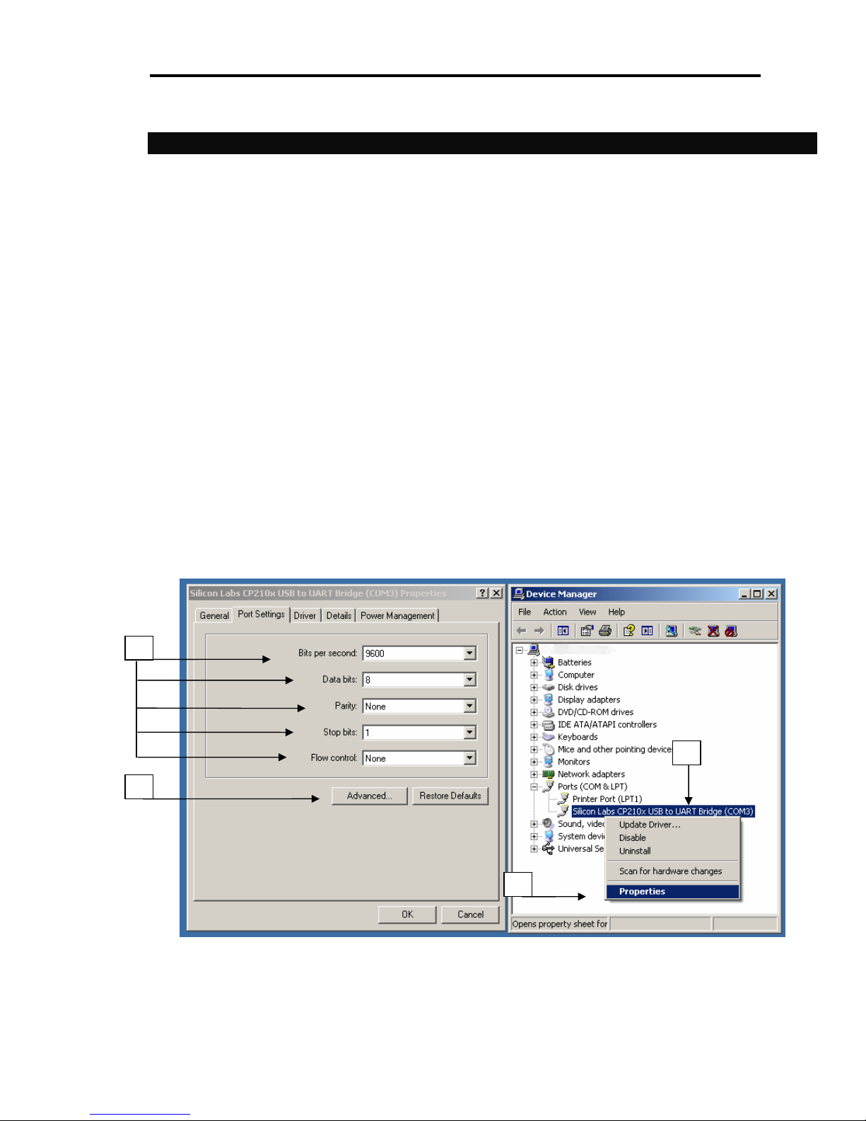
Once when you decided to change default settings follow to the next steps (Figures 9, 10):
1. Click “My computer” icon on your Desktop or click menu “Start” -> select “Properties” from
pop-up menu (Figure 9)
2. Select “Hardware” tab of “System properties” dialog (Figure 9)
3. Click “Device manager” button (Figure 9)
4. Expand tree of “Device manager” (Figure 9)
5. Click node named “Silicon Labs CP210x USB to UART Bridge (COM3)”***
6. Select “Properties” from pop-up menu.
7
8
6
Figure 10. Virtual COM port properties dialog
7. Use dropdown combo boxes to change port settings
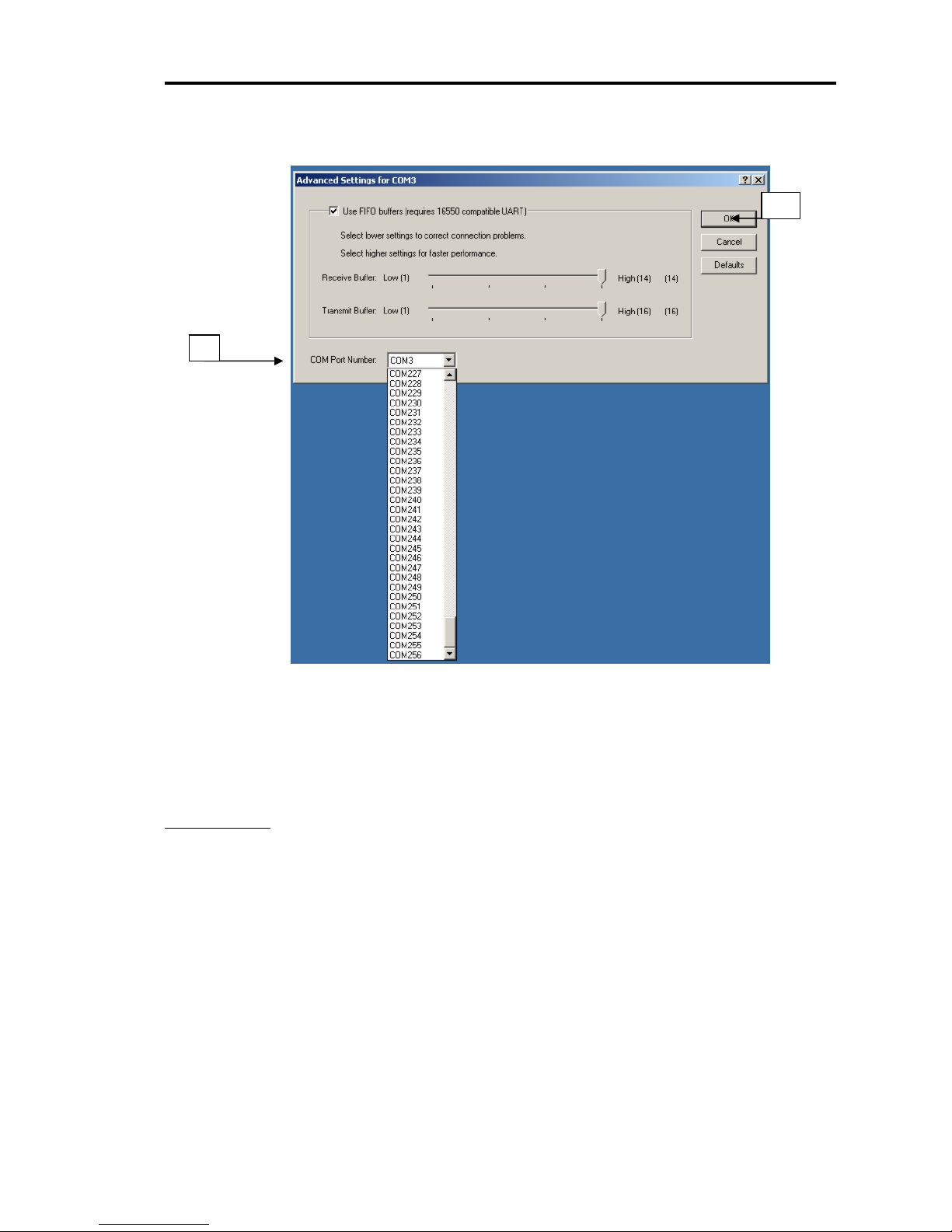
8. Click “Advanced” button (Figure 10) then you should see one more window (Figure11)
5
© Checkpoint LAB 2011
8
Page 9
Microcontroller-Café Checkpoint LAB
9. Select port number (available ports numbers 256) from the dropdown combo box labeled “COM
Port Number” (Figure 11).
10
9
Figure 11. Changing Virtual COM port number
10. Click “OK”
11. Follow back to the Virtual COM port properties dialog (Figure 10)
12. Click “OK” to save settings changes
APPENDIX
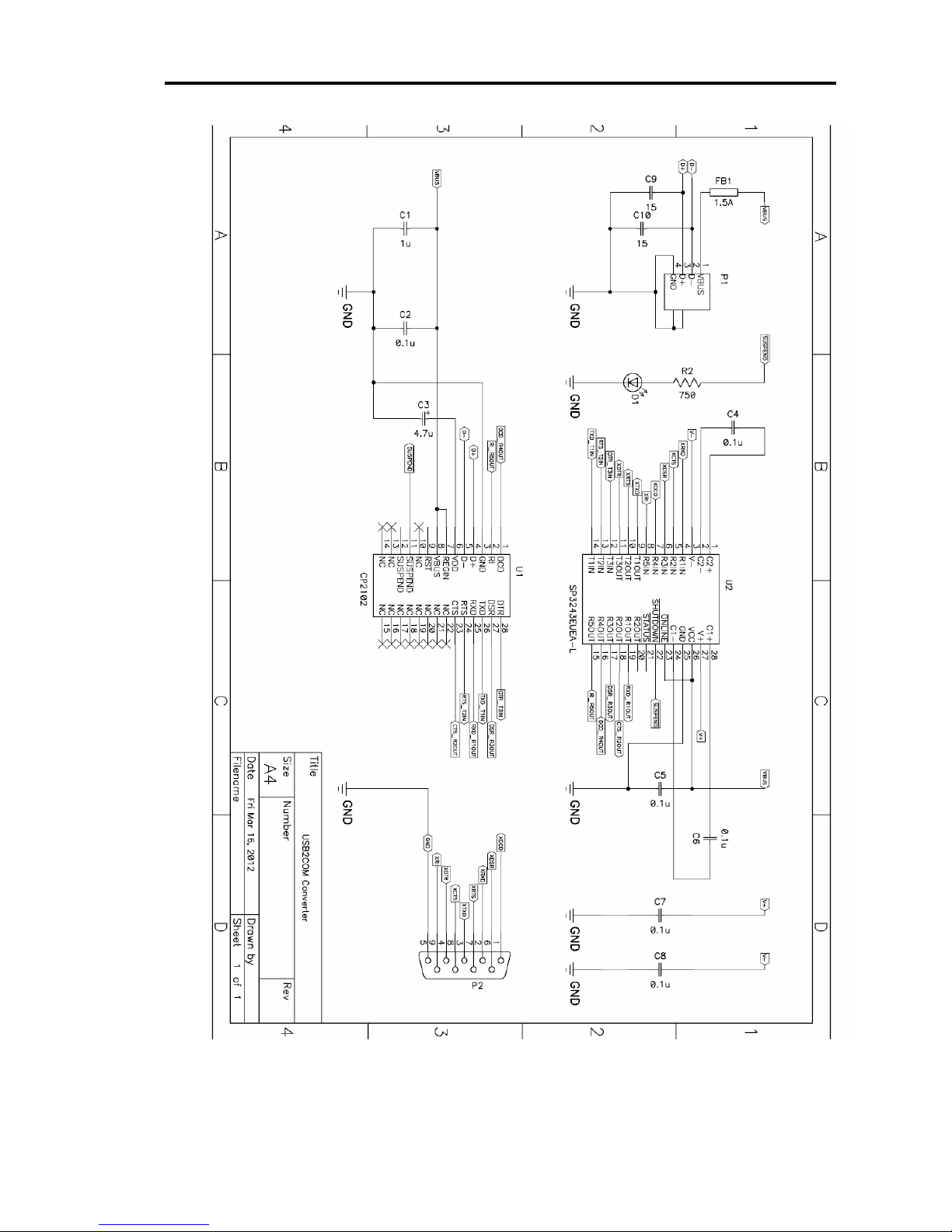
- USB-RS232 converter schematic picture (Figure 12)
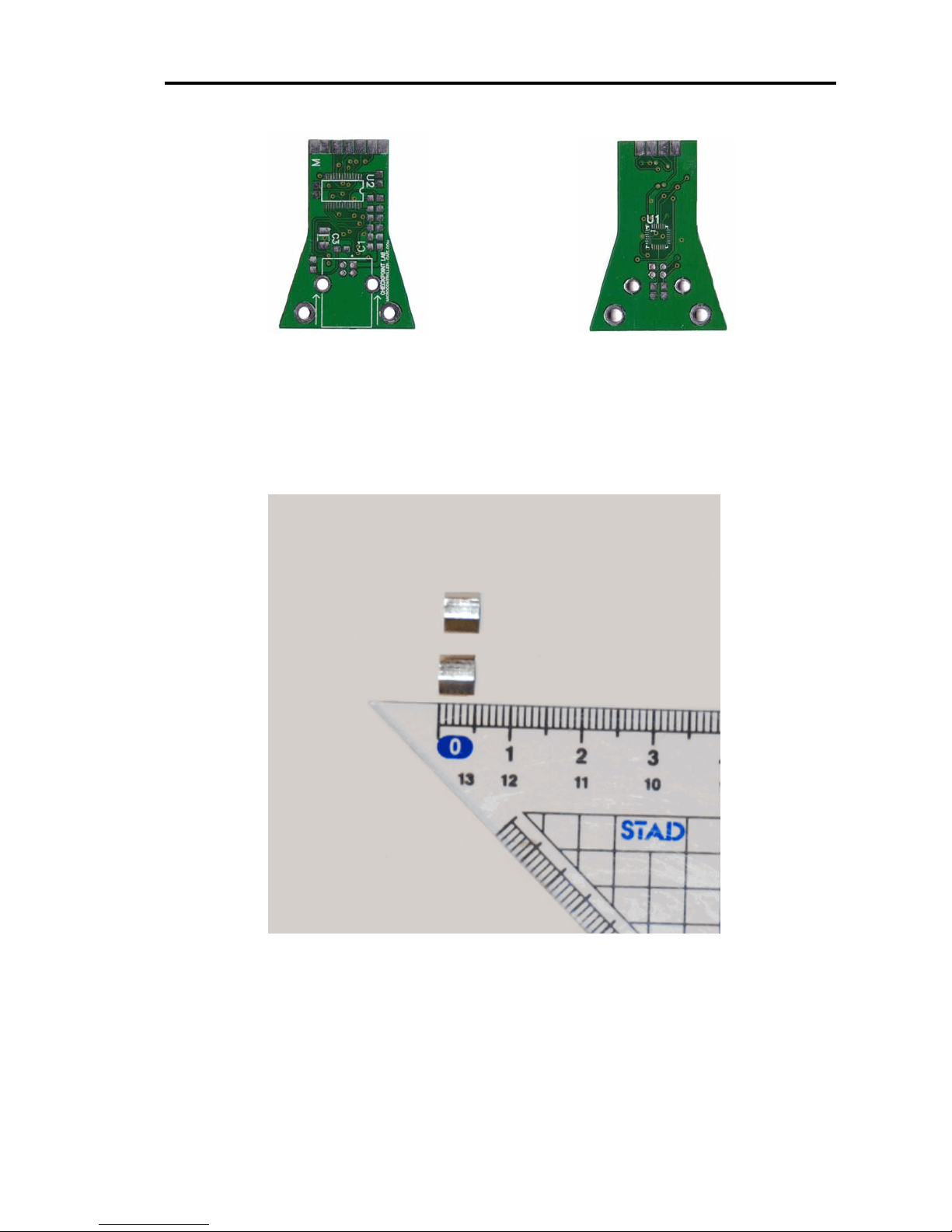
- PCB top/bottom side (Figure 13)
- PCB bottom stands (Figure 14)
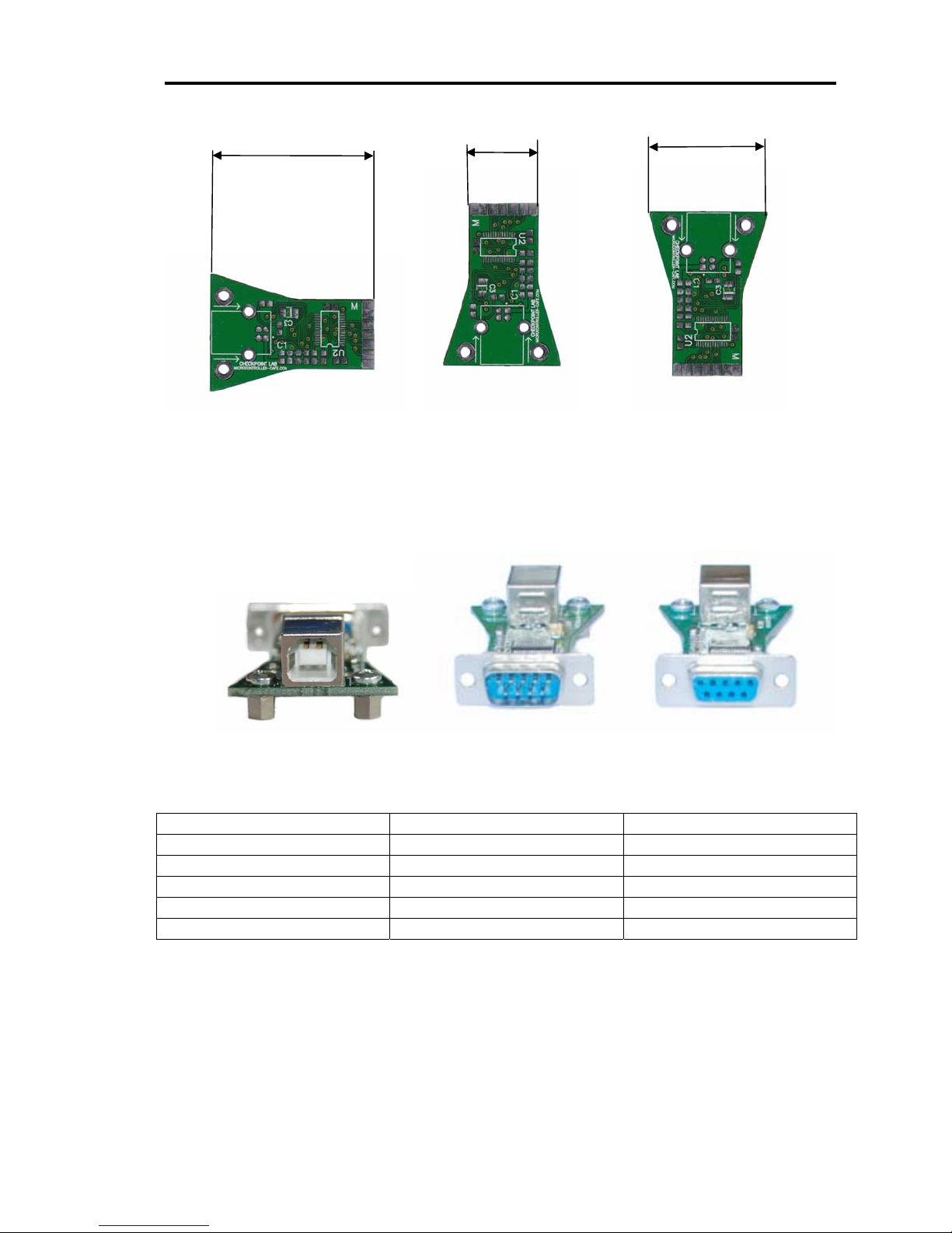
- PCB dimensions (Figure 15)
- USB port connector (Figure 16)
- DB-9 port connector (Figure 17)
- USB specification pins (Figure 18)
© Checkpoint LAB 2011
9
Page 10
Microcontroller-Café Checkpoint LAB
© Checkpoint LAB 2011
Figure 12. USB-RS232 converter schematic picture
10
Page 11
Microcontroller-Café Checkpoint LAB
Figure13. PCB top/bottom side
© Checkpoint LAB 2011
Figure 14. PCB bottom stands
11
Page 12
Microcontroller-Café Checkpoint LAB
44 mm 19 mm 32 mm
Figure 15. PCB dimensions
Figure 16. USB port connector Figure 17. DB-9 port connector M/F Types*****
Series A/B pin Conductor Cable Wire
1 VBUS (Vcc + 5V) RED
2 D - WHITE
3 D + GREEN
4 GND BLACK
Shell**** Shield DRAIN WIRE
Figure 18. USB specification pins
**** Applicable for original specifications only
***** M-type compatible with AVR STK-500 starter kit
© Checkpoint LAB 2011
12
 Loading...