

Page 1

Check Point
IP1280 Security Platform
Installation Guide
Part No. N450000891 Rev 001
Published March 2009
Page 2

© 2003-2009 Check Point Software Technologies Ltd.
All rights reserved. This product and related documentation are protected by copyright and
distributed under licensing restricting their use, copying, distribution, and decompilation. No
part of this product or related documentation may be reproduced in any form or by any means
without prior written authorization of Check Point. While every precaution has been taken in the
preparation of this book, Check Point assumes no responsibility for errors or omissions. This
publication and features described herein are subject to change without notice.
RESTRICTED RIGHTS LEGEND:
Use, duplication, or disclosure by the government is subject to restrictions as set forth in
subparagraph (c)(1)(ii) of the Rights in Technical Data and Computer Software clause at DFARS
252.227-7013 and FAR 52.227-19.
TRADEMARKS:
Please refer to http://www.checkpoint.com/copyright.html for a list of our trademarks.
For third party notices, see http://www.checkpoint.com/3rd_party_copyright.html.
Check Point Contact Information
For additional technical information about Check Point products, and for the latest version of
this document, see the Check Point Support Center at http://support.checkpoint.com/.
Check Point is engaged in a continuous effort to improve its documentation. Please help us by
sending your comments to:
2 Check Point IP1280 Security Platform Installation Guide
Page 3

Contents
Check Point Contact Information. . . . . . . . . . . . . . . . . . . . . . . . . . . . . . . . . . . . . . . 2
About this Guide . . . . . . . . . . . . . . . . . . . . . . . . . . . . . . . . . . . . . . . . . . . . . . . . . . 11
In this Guide . . . . . . . . . . . . . . . . . . . . . . . . . . . . . . . . . . . . . . . . . . . . . . . . . . . . . . . 11
Conventions this Guide Uses . . . . . . . . . . . . . . . . . . . . . . . . . . . . . . . . . . . . . . . . . . 12
Notices . . . . . . . . . . . . . . . . . . . . . . . . . . . . . . . . . . . . . . . . . . . . . . . . . . . . . . . . . 12
Text Conventions . . . . . . . . . . . . . . . . . . . . . . . . . . . . . . . . . . . . . . . . . . . . . . . . . 12
1 Overview . . . . . . . . . . . . . . . . . . . . . . . . . . . . . . . . . . . . . . . . . . . . . . . . . . . . . . . . 15
About the Check Point IP1280 Security Platform. . . . . . . . . . . . . . . . . . . . . . . . . . . 15
Managing the Check Point IP1280 Security Platform . . . . . . . . . . . . . . . . . . . . . . . 16
Check Point IP1280 Security Platform Overview . . . . . . . . . . . . . . . . . . . . . . . . . . . 17
Built-In Ethernet Ports . . . . . . . . . . . . . . . . . . . . . . . . . . . . . . . . . . . . . . . . . . . . . . 17
Expansion Slots. . . . . . . . . . . . . . . . . . . . . . . . . . . . . . . . . . . . . . . . . . . . . . . . . . . 18
Console Port . . . . . . . . . . . . . . . . . . . . . . . . . . . . . . . . . . . . . . . . . . . . . . . . . . . . . 18
Auxiliary Port . . . . . . . . . . . . . . . . . . . . . . . . . . . . . . . . . . . . . . . . . . . . . . . . . . . . . 19
System Status LEDs . . . . . . . . . . . . . . . . . . . . . . . . . . . . . . . . . . . . . . . . . . . . . . . 19
Hard-Disk Drives . . . . . . . . . . . . . . . . . . . . . . . . . . . . . . . . . . . . . . . . . . . . . . . . . . 21
Using RAID-1 . . . . . . . . . . . . . . . . . . . . . . . . . . . . . . . . . . . . . . . . . . . . . . . . . . . 21
Hard-Disk Drive Hot Swap Feature . . . . . . . . . . . . . . . . . . . . . . . . . . . . . . . . . . 22
Hard-Disk Drive LEDs . . . . . . . . . . . . . . . . . . . . . . . . . . . . . . . . . . . . . . . . . . . . 22
Power Supplies and Fan Unit . . . . . . . . . . . . . . . . . . . . . . . . . . . . . . . . . . . . . . . . 24
Power Supplies . . . . . . . . . . . . . . . . . . . . . . . . . . . . . . . . . . . . . . . . . . . . . . . . . 24
Fan Unit . . . . . . . . . . . . . . . . . . . . . . . . . . . . . . . . . . . . . . . . . . . . . . . . . . . . . . . 26
Site Requirements . . . . . . . . . . . . . . . . . . . . . . . . . . . . . . . . . . . . . . . . . . . . . . . . . . 26
Safety Warnings and Cautions. . . . . . . . . . . . . . . . . . . . . . . . . . . . . . . . . . . . . . . . . 26
Software Requirements . . . . . . . . . . . . . . . . . . . . . . . . . . . . . . . . . . . . . . . . . . . . . . 27
Product Disposal . . . . . . . . . . . . . . . . . . . . . . . . . . . . . . . . . . . . . . . . . . . . . . . . . . . 28
2 Installing the Check Point IP1280 Appliance . . . . . . . . . . . . . . . . . . . . . . . . . . . 29
Rack Mounting the Appliance. . . . . . . . . . . . . . . . . . . . . . . . . . . . . . . . . . . . . . . . . . 29
Before You Begin . . . . . . . . . . . . . . . . . . . . . . . . . . . . . . . . . . . . . . . . . . . . . . . . . . . 30
Check Point IP1280 Security Platform Installation Guide 3
Page 4

3 Performing the Initial Configuration . . . . . . . . . . . . . . . . . . . . . . . . . . . . . . . . . . . 37
Using a Console Connection. . . . . . . . . . . . . . . . . . . . . . . . . . . . . . . . . . . . . . . . . . 38
Connecting Power and Turning the Power On . . . . . . . . . . . . . . . . . . . . . . . . . . . . 39
Performing the Initial Configuration. . . . . . . . . . . . . . . . . . . . . . . . . . . . . . . . . . . . . 40
Connecting Network Interfaces . . . . . . . . . . . . . . . . . . . . . . . . . . . . . . . . . . . . . . . . 42
Using Check Point Network Voyager . . . . . . . . . . . . . . . . . . . . . . . . . . . . . . . . . . . 42
Viewing Check Point IPSO Documentation by Using
Check Point Network Voyager . . . . . . . . . . . . . . . . . . . . . . . . . . . . . . . . . . . . . 43
Using the Command-Line Interface . . . . . . . . . . . . . . . . . . . . . . . . . . . . . . . . . . . . 44
Using Check Point Horizon Manager . . . . . . . . . . . . . . . . . . . . . . . . . . . . . . . . . . . 44
4 Installing and Replacing Network Interface Cards and ADP Services Modules 47
Removing, Installing, and Replacing NICs and ADP Modules . . . . . . . . . . . . . . . . 48
Before You Begin . . . . . . . . . . . . . . . . . . . . . . . . . . . . . . . . . . . . . . . . . . . . . . . . . 48
Configuring and Activating Interfaces . . . . . . . . . . . . . . . . . . . . . . . . . . . . . . . . . . . 60
Monitoring Network Interface Cards or ADP Modules . . . . . . . . . . . . . . . . . . . . . . 60
5 About IP1280 Appliance Network Interface Cards . . . . . . . . . . . . . . . . . . . . . . . 61
Four-Port 10/100 Ethernet NICs . . . . . . . . . . . . . . . . . . . . . . . . . . . . . . . . . . . . . . . 62
10/100 Ethernet NIC Features . . . . . . . . . . . . . . . . . . . . . . . . . . . . . . . . . . . . . . . 62
Ethernet NIC Connectors and Cables . . . . . . . . . . . . . . . . . . . . . . . . . . . . . . . . . 63
Two-Port Fiber-Optic Gigabit Ethernet NICs. . . . . . . . . . . . . . . . . . . . . . . . . . . . . . 64
Fiber-Optic Gigabit Ethernet NIC Features . . . . . . . . . . . . . . . . . . . . . . . . . . . . . 64
Fiber-Optic Gigabit Ethernet NIC Connectors and Cables. . . . . . . . . . . . . . . . . . 65
Performance Considerations . . . . . . . . . . . . . . . . . . . . . . . . . . . . . . . . . . . . . . . . 65
Two-Port and Four-Port Copper Gigabit Ethernet NIC . . . . . . . . . . . . . . . . . . . . . . 66
Copper Gigabit Ethernet NIC Features . . . . . . . . . . . . . . . . . . . . . . . . . . . . . . . . 66
Performance Considerations . . . . . . . . . . . . . . . . . . . . . . . . . . . . . . . . . . . . . . . . 67
Two-Port Copper Gigabit Ethernet NIC Connectors and Cables . . . . . . . . . . . . . 67
6 About IP1280 Appliance ADP Services Modules . . . . . . . . . . . . . . . . . . . . . . . . 69
Installing and Replacing ADP Modules . . . . . . . . . . . . . . . . . . . . . . . . . . . . . . . . . . 70
Before You Begin . . . . . . . . . . . . . . . . . . . . . . . . . . . . . . . . . . . . . . . . . . . . . . . 70
Using ADP Transceivers in ADP Modules . . . . . . . . . . . . . . . . . . . . . . . . . . . . . . . 74
Identifying ADP Module and Transceiver Types with Latch Lever Color Codes. . . 75
Check Point ADP Module LED Reference Information . . . . . . . . . . . . . . . . . . . . . . 75
Configuring Check Point IPSO for IP1280 ADP Interfaces . . . . . . . . . . . . . . . . . . . 76
Effect on Interfaces . . . . . . . . . . . . . . . . . . . . . . . . . . . . . . . . . . . . . . . . . . . . . . . 76
Check Point ADP Module Interface Names for IP1280 Appliances . . . . . . . . . . . 76
Configuring Network Topology with an IP1280 Appliance . . . . . . . . . . . . . . . . . . 77
Configuration Example with VRRP . . . . . . . . . . . . . . . . . . . . . . . . . . . . . . . . . . . 77
Deleting VRRP Configurations . . . . . . . . . . . . . . . . . . . . . . . . . . . . . . . . . . . . . 79
Reconfiguring Interfaces . . . . . . . . . . . . . . . . . . . . . . . . . . . . . . . . . . . . . . . . . . 80
4 Check Point IP1280 Security Platform Installation Guide
Page 5

Reconfiguring VRRP . . . . . . . . . . . . . . . . . . . . . . . . . . . . . . . . . . . . . . . . . . . . . 83
7 Installing and Replacing Components Other than Network Interface Cards (NICs)
and Accelerated Data Path (ADP) Services Modules . . . . . . . . . . . . . . . . . . . . . 85
Replacing the Check Point Encryption Accelerator Card. . . . . . . . . . . . . . . . . . . . . 86
Configuring Software to Use Hardware Acceleration . . . . . . . . . . . . . . . . . . . . . . 88
Installing or Replacing Hard-Disk Drives . . . . . . . . . . . . . . . . . . . . . . . . . . . . . . . . . 88
Hard-Disk Drive Hot Swap Feature . . . . . . . . . . . . . . . . . . . . . . . . . . . . . . . . . . . . 89
Before You Begin . . . . . . . . . . . . . . . . . . . . . . . . . . . . . . . . . . . . . . . . . . . . . . . . . 90
Removing and Replacing a Hard-Disk Drive . . . . . . . . . . . . . . . . . . . . . . . . . . . 90
Installing a PC Card . . . . . . . . . . . . . . . . . . . . . . . . . . . . . . . . . . . . . . . . . . . . . . . . . 95
Storing System Logs on the Flash-Memory PC Card . . . . . . . . . . . . . . . . . . . . . 101
Disabling Flash-Memory PC Cards . . . . . . . . . . . . . . . . . . . . . . . . . . . . . . . . . . . 101
Transferring Files with the Flash-Memory PC Card . . . . . . . . . . . . . . . . . . . . . . 102
Replacing the Compact Flash Memory Card . . . . . . . . . . . . . . . . . . . . . . . . . . . . . 103
Replacing or Upgrading Memory . . . . . . . . . . . . . . . . . . . . . . . . . . . . . . . . . . . . . . 107
Before You Begin . . . . . . . . . . . . . . . . . . . . . . . . . . . . . . . . . . . . . . . . . . . . . . . . 108
Installing or Replacing a Fan Unit . . . . . . . . . . . . . . . . . . . . . . . . . . . . . . . . . . . . . 113
Before You Begin . . . . . . . . . . . . . . . . . . . . . . . . . . . . . . . . . . . . . . . . . . . . . . . . 113
Installing or Replacing a Power Supply . . . . . . . . . . . . . . . . . . . . . . . . . . . . . . . . . 115
Before You Begin . . . . . . . . . . . . . . . . . . . . . . . . . . . . . . . . . . . . . . . . . . . . . . . . 116
Monitoring the Power Supply . . . . . . . . . . . . . . . . . . . . . . . . . . . . . . . . . . . . . . . 117
Replacing the Motherboard Battery . . . . . . . . . . . . . . . . . . . . . . . . . . . . . . . . . . . . 118
8 Troubleshooting . . . . . . . . . . . . . . . . . . . . . . . . . . . . . . . . . . . . . . . . . . . . . . . . . 123
General Troubleshooting Information. . . . . . . . . . . . . . . . . . . . . . . . . . . . . . . . . . . 123
A Technical Specifications . . . . . . . . . . . . . . . . . . . . . . . . . . . . . . . . . . . . . . . . . . 129
Space Requirements . . . . . . . . . . . . . . . . . . . . . . . . . . . . . . . . . . . . . . . . . . . . . . . 129
B Compliance Information . . . . . . . . . . . . . . . . . . . . . . . . . . . . . . . . . . . . . . . . . . . 131
Declaration of Conformity. . . . . . . . . . . . . . . . . . . . . . . . . . . . . . . . . . . . . . . . . . . . 131
Compliance Statements . . . . . . . . . . . . . . . . . . . . . . . . . . . . . . . . . . . . . . . . . . . . . 132
FCC Notice (US) . . . . . . . . . . . . . . . . . . . . . . . . . . . . . . . . . . . . . . . . . . . . . . . . . . 132
Index . . . . . . . . . . . . . . . . . . . . . . . . . . . . . . . . . . . . . . . . . . . . . . . . . . . . . . . . . . . 135
Check Point IP1280 Security Platform Installation Guide 5
Page 6

6 Check Point IP1280 Security Platform Installation Guide
Page 7

Figures
Figure 1 Component Locations Front View . . . . . . . . . . . . . . . . . . . . . . . . . . . . . . 17
Figure 2 Built-In Ethernet Ports Details . . . . . . . . . . . . . . . . . . . . . . . . . . . . . . . . . 17
Figure 3 Check Point IP1280 Appliance System Status LEDs . . . . . . . . . . . . . . . 20
Figure 4 Hard-Disk Drive Front Pane . . . . . . . . . . . . . . . . . . . . . . . . . . . . . . . . . . 22
Figure 5 Power Supply and Fan Unit Locations (AC version) . . . . . . . . . . . . . . . . 24
Figure 6 Power Supply and Fan Unit Locations (DC version) . . . . . . . . . . . . . . . . 24
Figure 7 Power Supply Status LED Location . . . . . . . . . . . . . . . . . . . . . . . . . . . . 26
Figure 8 Front Rack-Mounting Screw Locations . . . . . . . . . . . . . . . . . . . . . . . . . . 30
Figure 9 Power Switch Location . . . . . . . . . . . . . . . . . . . . . . . . . . . . . . . . . . . . . . 39
Figure 10 Check Point Network Voyager Reference Access Points . . . . . . . . . . . 43
Figure 11 Four-Port 10/100 Ethernet NIC Front Panel Details . . . . . . . . . . . . . . . 62
Figure 12 Output Connector for the Ethernet Cable . . . . . . . . . . . . . . . . . . . . . . . 63
Figure 13 Ethernet Crossover-Cable Pin Connections . . . . . . . . . . . . . . . . . . . . . 63
Figure 14 PMC Two-Port Short-Range Gigabit Ethernet NIC . . . . . . . . . . . . . . . . 64
Figure 15 PMC Two-Port Long-Range Gigabit Ethernet NIC . . . . . . . . . . . . . . . . 65
Figure 16 Two-Port Copper Gigabit Ethernet NIC Front Panel Details . . . . . . . . . 66
Figure 17 Four-Port Copper Gigabit Ethernet NIC Front Panel Details . . . . . . . . 67
Figure 18 Ethernet Cable Connector Output Pin Assignments . . . . . . . . . . . . . . . 68
Figure 19 Ethernet Crossover Cable Pin Connections . . . . . . . . . . . . . . . . . . . . . 68
Figure 20 ADP Module Front Panel Details and LED Information . . . . . . . . . . . . 73
Figure 21 Location of Hard-Disk Drives . . . . . . . . . . . . . . . . . . . . . . . . . . . . . . . . 89
Figure 22 Slot 3 PC Card Location . . . . . . . . . . . . . . . . . . . . . . . . . . . . . . . . . . . . 96
Check Point IP1280 Security Platform Installation Guide 7
Page 8

8 Check Point IP1280 Security Platform Installation Guide
Page 9

Tables
Table 1 Text Conventions . . . . . . . . . . . . . . . . . . . . . . . . . . . . . . . . . . . . . . . . . . . 12
Table 2 Pin Assignments for Console Connector and Console Cable . . . . . . . . . 18
Table 3 System Status LEDs . . . . . . . . . . . . . . . . . . . . . . . . . . . . . . . . . . . . . . . . 20
Table 4 Hard-Disk Drive LEDs . . . . . . . . . . . . . . . . . . . . . . . . . . . . . . . . . . . . . . . 23
Table 5 Power Supply Status LEDs . . . . . . . . . . . . . . . . . . . . . . . . . . . . . . . . . . . 25
Table 6 Check Point IP1280 Disk-Based Security Platform Software Requirements
27
Table 7 Check Point IP1280 Flash-Based Security Platform Software Requirements
28
Table 8 NIC PCI Frequency . . . . . . . . . . . . . . . . . . . . . . . . . . . . . . . . . . . . . . . . . 61
Table 9 Identifying ADP Modules and Transceivers . . . . . . . . . . . . . . . . . . . . . . . 75
Check Point IP1280 Security Platform Installation Guide 9
Page 10

10 Check Point IP1280 Security Platform Installation Guide
Page 11

About this Guide
This manual provides information for the installation and use of the Check Point IP1280 security
platforms. Installation and maintenance should be performed by experienced technicians or
Check Point-approved service providers only.
This preface provides the following information:
In this Guide
Conventions this Guide Uses
In this Guide
This guide is organized into the following chapters and appendixes:
Chapter 1, “Overview” presents a general overview of the Check Point IP1280 Security
Platform.
Chapter 2, “Installing the Check Point IP1280 Appliance” describes how to install the Check
Point IP1280 appliance.
Chapter 3, “Performing the Initial Configuration” describes how to physically connect it to a
network and to a power source and how to make the appliance available on the network.
Chapter 4, “Installing and Replacing Network Interface Cards and ADP Services Modules”
describes how to install, monitor, and replace network interface cards (NICs) and Check
Point Accelerated Data Path (ADP) services modules for IP appliances.
Chapter 5, “About IP1280 Appliance Network Interface Cards” describes how to connect to
and use each of the supported NICs.
Chapter 6, “About IP1280 Appliance ADP Services Modules” describes how to connect to
and use each of the supported Accelerated Data Path (ADP) services modules.
Chapter 7, “Installing and Replacing Components Other than Network Interface Cards
(NICs) and Accelerated Data Path (ADP) Services Modules” describes how to install or
replace parts, other than NICs and ADP modules, that you can order from Check Point.
Chapter 8, “Troubleshooting” discusses problems you might encounter and proposes
solutions to these problems.
Appendix A, “Technical Specifications” provides technical specifications such as interface
characteristics.
Appendix B, “Compliance Information” provides compliance and regulatory information.
Check Point IP1280 Security Platform Installation Guide 11
Page 12

2
Warning
Caution
Note
Conventions this Guide Uses
The following sections describe the conventions this guide uses, including notices, text
conventions, and command-line conventions.
Notices
Warnings advise the user that either bodily injury might occur because of a physical hazard,
or that damage to a structure, such as a room or equipment closet, might occur because of
equipment damage.
Cautions indicate potential equipment damage, equipment malfunction, loss of
performance, loss of data, or interruption of service.
Notes provide information of special interest or recommendations.
Text Conventions
Table 1 describes the text conventions this guide uses.
Table 1 Text Conventions
Convention Description
monospace font
bold monospace font
Key names Keys that you press simultaneously are linked by a plus sign (+):
Menu commands Menu commands are separated by a greater than sign (>):
Indicates command syntax, or represents computer or screen
output, for example:
Log error 12453
Indicates text you enter or type, for example:
# configure nat
Press Ctrl + Alt + Del.
Choose File > Open.
12 Check Point IP1280 Security Platform Installation Guide
Page 13

Conventions this Guide Uses
Table 1 Text Conventions
Convention Description
The words enter and type Enter indicates that you type something and then press the
Return or Enter key.
Do not press the Return or Enter key when an instruction says
type.
Italics
• Emphasizes a point or denotes new terms at the place where
they are defined in the text.
• Indicates an external book title reference.
• Indicates a variable in a command:
delete interface
if_name
Check Point IP1280 Security Platform Installation Guide 13
Page 14

2
14 Check Point IP1280 Security Platform Installation Guide
Page 15

1 Overview
This chapter provides an overview of the Check Point IP1280 security platform and the
requirements for its use. The following topics are covered:
About the Check Point IP1280 Security Platform
Managing the Check Point IP1280 Security Platform
Check Point IP1280 Security Platform Overview
Site Requirements
Safety Warnings and Cautions
Software Requirements
Product Disposal
About the Check Point IP1280 Security Platform
The Check Point IP1280 is a high-end, next-generation security appliance designed for the
demanding price performance, multi-Gigabit Ethernet throughput, and port-density
requirements of large enterprises and carriers. The IP1280 supports quad-core technology and is
purpose-built to run Check Point VPN-1, Check Point VPN-1 UTM, and next-generation, multithreaded enterprise security applications such as Check Point CoreXL. The IP1280 is optimized
to provide scalability, reliability, and investment protection into the next decade. In addition, the
IP1280 allows you to boost performance as needed through next-generation, high-end Check
Point Accelerated Data Path (ADP) services modules for IP appliances and Check Point IPSO
for IP appliances system upgrades.
The IP1280 appliance is available as either a or flash-based platform. In base configurations, the
IP1280 disk-based appliance ships with one hard-disk drive, and the flash-based appliance ships
with high-capacity compact flash memory.
The IP1280 security platform is a two-rack unit appliance that incorporates a serviceable
slide-out chassis tray assembly into design. The front panel of the IP1280 security platform has
two interface slots that support hot-swapping operations. Optional PMC carriers can be inserted
into slots 1 and 2. Each PMC carrier supports two PMC network interface cards (NICs) for a
total of four NICs. Alternatively, you can install one ADP module in either slot 1 or 2. These
network interfaces provide exceptional data forwarding and monitoring performance when used
with Check Point and partner applications.
The front panel of the IP1280 security platform also contains:
IP1280 Security Platform Installation Guide 15
Page 16

1 Overview
Two additional single-NIC slots (slots 3 and 4), one of which (slot 4) is pre-populated with a
four-port 1000 BASE-T Ethernet interface
Console port
Serial port
The network interfaces in the external PMC slot are designated for management, monitoring,
and high-availability traffic. Partner application and operating system storage is provided on the
hard-disk drive in disk-based systems or in flash memory in flash-based systems.
The IP1280 security platform is designed to meet other mid- to high-end availability
requirements, including port density for connections to redundant internal, external, DMZ, and
management networks. In addition, the IP1280 security platform provides redundant power
supplies, N + 1 cooling, and hot swapping of hard-disk drives and PMC NICs.
As a network device, the IP1280 security platform supports a comprehensive suite of IP-routing
functions and protocols.
The integrated router functionality eliminates the need for separate intranet and access routers in
security applications.
Managing the Check Point IP1280 Security Platform
You can manage the Check Point IP1280 security platform by using the following interfaces:
Check Point Network Voyager for IP appliances—an SSL-secured, Web-based element
management interface to Check Point IP security platforms. Check Point Network Voyager
is preinstalled on the IP1280 security platform and enabled through the Check Point IPSO
operating system. With Check Point Network Voyager, you can manage, monitor, and
configure the IP1280 security platform from any authorized location within the network by
using a standard Web browser. Use one of the four Ethernet management ports to access the
Check Point Network Voyager interface.
For information about how to access Check Point Network Voyager and the related
reference materials, see “Using Check Point Network Voyager” on page 42.
The Check Point IPSO command-line interface (CLI)—an SSHv2-secured interface that
enables you to easily configure Check Point IP security platforms from the command line.
Nearly everything that you can accomplish with Check Point Network Voyager—manage,
monitor, and configure the IP1280 security platform —you can also do with the CLI.
For information about how to access the CLI, see the CLI Reference Guide for Check Point
IPSO v3.6 or later.
Check Point Horizon Manager for IP appliances—a secure GUI-based software image
management application. With Check Point Horizon Manager, you can securely install and
upgrade the Check Point IPSO operating system and applications such as Check Point
VPN-1. Check Point Horizon Manager can perform installations and upgrades on up to
2,500 Check Point IP security platforms, offering administrators the most rapid and
dependable method to perform Check Point application upgrades.
For information about how to obtain Check Point Horizon Manager, see the Check Point
Web site at www.checkpoint.com.
16 IP1280 Security Platform Installation Guide
Page 17
Check Point IP1280 Security Platform Overview
Note
IP1280
RESET
00616a.1
CONSOLE AUX AUX2
HDD B
SLOT 3
SLOT 2
SLOT 1
HDD A
HOT SWAP
HOT SWAP
POWER
ACTIVITY
HARD DRIVE
STATUS
HOT SWAP
HOT SWAP
POWER
ACTIVITY
HARD DRIVE
STATUS
SLOT 4
1000BaseT
PC CARD
1
2
3
4
SUB SLOT 1 SUB SLOT 2
POWER
READY REQUEST
HOT SWAP
FIO CARRIER
1000B-LX
ACT
LINK
SUB SLOT 1 SUB SLOT 2
POWER
READY REQUEST
HOT SWAP
FIO CARRIER
1000B-LX
ACT
LINK
V2
1000BaseT
ACT
LINK
ACT
LINK
V2
1000BaseT
ACT
LINK
ACT
LINK
Dual 6U PMC carrier
(slots 1 and 2)
Console port
System status LEDs
PMC slot 3
Four-port Gigabit
Ethernet
(PMC slot 4)
Serial (AUX) port
Hard-disk drive A
Hard-disk drive B
Grounding plug
Hard-disk drive hot swap buttons
00620
1000BaseT
1
2
3
4
RJ-45 connectors
LInk LEDs (green)
Port 3
Port 4
Port 2
Port 1
Check Point IP1280 Security Platform Overview
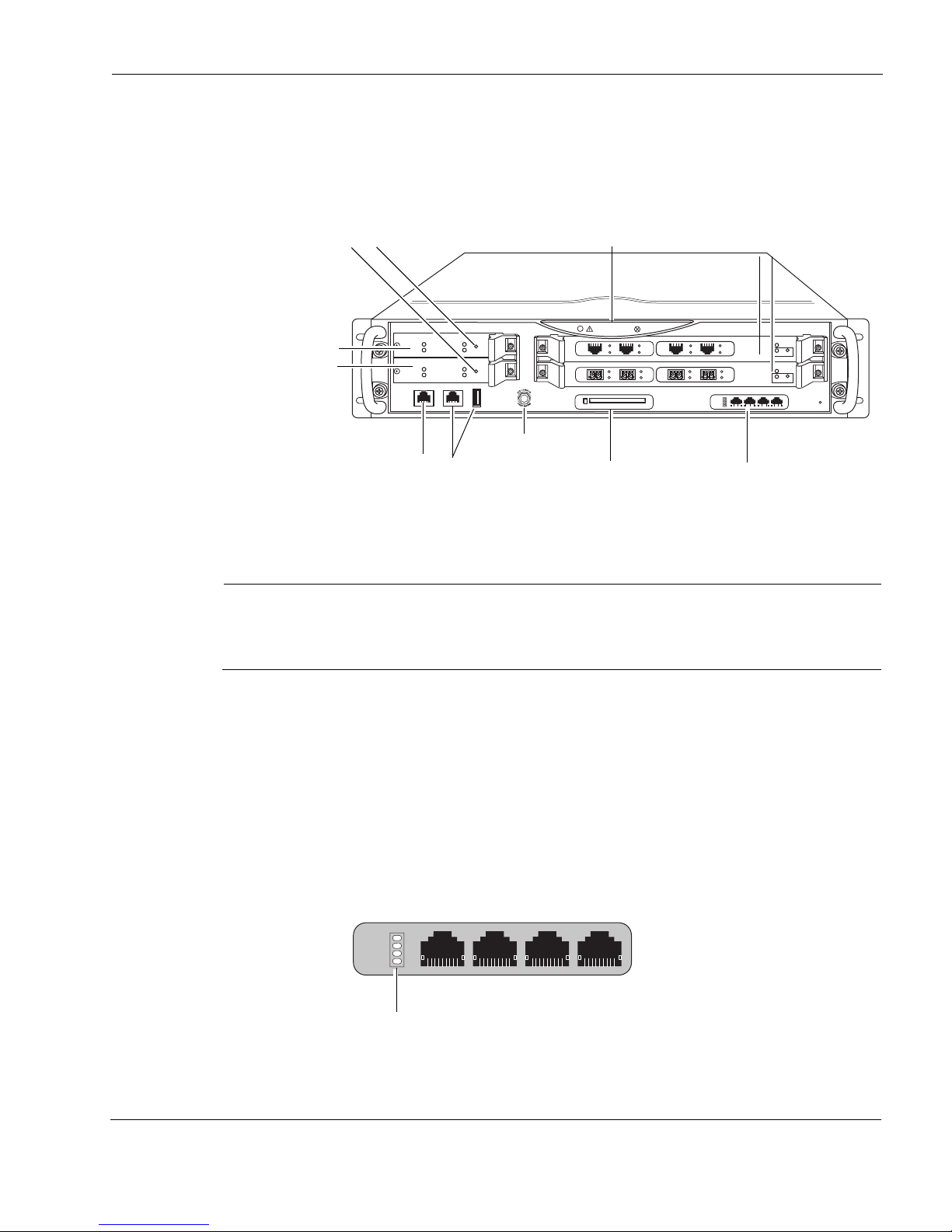
Figure 1 shows the component locations for the Check Point IP1280 security platform.
Figure 1 Component Locations Front View
Built-In Ethernet Ports
IP1280 base systems do not include dual 6U PMC carriers, and you must order those
separately from your Check Point representative. For Check Point contact information, see
“Check Point Contact Information” on page 2.
The built-in Gigabit Ethernet ports are located in slot 4. Figure 2 shows the layout of the
Ethernet ports and link LEDs. The top link LED represents the left-most port (port 1). The
remaining LEDs represent the remaining ports from top to bottom and left to right.
Figure 2 Built-In Ethernet Ports Details
IP1280 Security Platform Installation Guide 17
Page 18

1 Overview
Caution
Note
Cables that connect to the Gigabit Ethernet NIC must be IEEE 802.3 compliant to
prevent potential data loss.
Expansion Slots
The IP1280 appliance uses two 6U dual PMC carriers (or one PMC carrier and one ADP
module) in slot 1 and slot 2 along with single-NIC slots 3 and 4 to provide up to a total of six
expansion subslots for NICs. For more information about NICs and ADP modules that the
IP1280 supports, see Chapter 5, “About IP1280 Appliance Network Interface Cards” and
Chapter 6, “About IP1280 Appliance ADP Services Modules”.
Check Point products support only NICs and ADP modules purchased from Check Point or
Check Point-approved resellers. Check Point support services can provide support only for
Check Point products that use Check Point-approved accessories. For sales or reseller
information, see the Check Point Web site at www.checkpoint.com.
Console Port
The default configuration of the serial ports are: 9600 baud, 8 bits, no parity, and 1 stop. Table 2
provides pin assignment information for console connections. If you need to access the device
locally, you must use the console port.
Table 2 Pin Assignments for Console Connector and Console Cable
Console Port
(DTE)
Signal RJ-45 Pin RJ-45 Pin DB-9 Pin Signal
RTS 1 8 8 CTS
DTR 2 7 6 DSR
TxD 3 6 2 RxD
GND 4 5 5 GND
GND 5 4 5 GND
RxD 6 3 3 TxD
RJ-45 to RJ-45 Rollover
Cable
RJ-45 to DB-9
Ter min al
Adapter Console Device
18 IP1280 Security Platform Installation Guide
Page 19

Check Point IP1280 Security Platform Overview
Note
RJ-45 to DB-9
Console Port
(DTE)
DSR 7 2 4 DTR
CTS 8 1 7 RTS
RJ-45 to RJ-45 Rollover
Cable
Ter min al
Adapter Console Device
The console cable provided with the IP1280 is comprised of two parts:
A 6’ rollover cable with RJ-45 terminations
An RJ-45 to DB-9 adapter
One RJ-45 termination has a retractable shroud that releases or secures the RJ-45 tab. Use this
end of the cable when connecting to the console port of the IP1280. You can easily remove the
console cable by pulling back on the shroud.
On the opposite end of the console cable, connect the RJ-45 to the DB-9 adapter, which you can
then connect to the host terminal.
Auxiliary Port
Use the built-in serial (AUX) port, shown in Figure 1, to establish a modem connection for
managing the appliance remotely or out-of-band. Use USB cables with a standard USB A-style
connector and pinout for the AUX port. For Check Point approved modem connections, you will
need a USB to RS232 adaptor.
The only modem approved for use with Check Point security appliances with USB AUX
ports is the Radicom model V92MB-U-E, and you must be using Check Point IPSO 6.1 or
greater.
System Status LEDs
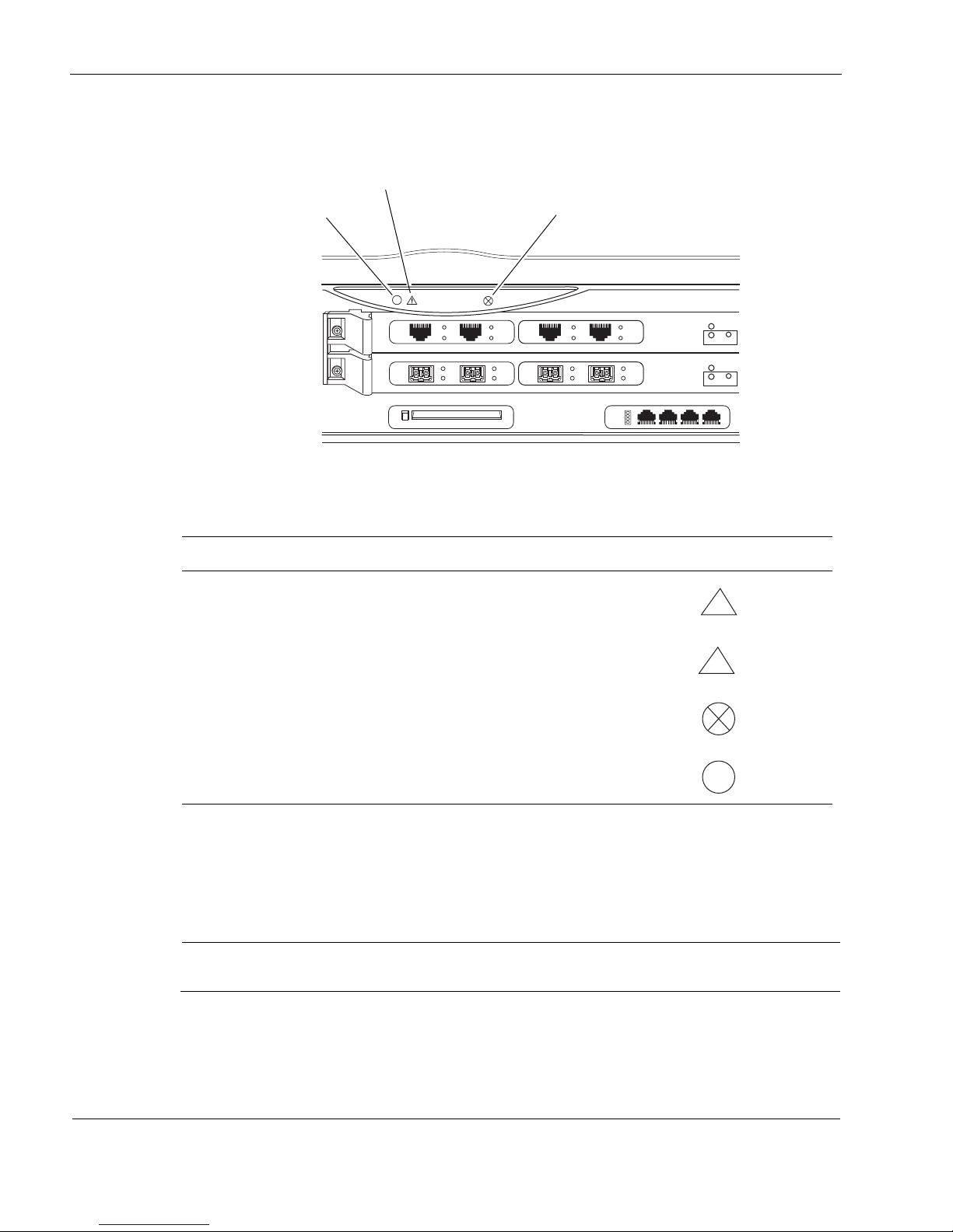
You can visually monitor the status of the Check Point IP1280 appliance by checking the system
status LEDs. The system status LEDs are located on the center of the front panel, as shown in
Figure 3.
IP1280 Security Platform Installation Guide 19
Page 20
1 Overview
Note
00617.1
SLOT 3
SLOT 2
SLOT 1
SLOT 4
1000BaseT
PC CARD
1
2
3
4
SUB SLOT 1 SUB SLOT 2
POWER
READY REQUEST
HOT SWAP
FIO CARRIER
1000B-LX
ACT
LINK
SUB SLOT 1 SUB SLOT 2
POWER
READY REQUEST
HOT SWAP
FIO CARRIER
1000B-LX
ACT
LINK
V2
1000BaseT
ACT
LINK
ACT
LINK
V2
1000BaseT
ACT
LINK
ACT
LINK
Fault (red)
Warning
(yellow)
System OK
(green)
!
!
Figure 3 Check Point IP1280 Appliance System Status LEDs
Table 3 shows the system status LEDs and describes their meaning.
Table 3 System Status LEDs
Status Indicator Meaning Symbol
Solid yellow Appliance is experiencing an internal voltage problem.
Blinking yellow Appliance is experiencing a temperature problem.
Solid red One or more fans are not operating properly.
Power supply over temperature fault.
Blinking green System activity indicator
The location and meaning of the status LEDs for the installed network interface cards (NICs) is
described in Chapter 5, “About IP1280 Appliance Network Interface Cards.”
The location and meaning of the status LEDs for the installed ADP modules is described in
Chapter 6, “About IP1280 Appliance ADP Services Modules.”
The symbols in Table 3 are visibly only if there is an alarm condition, as specified.
20 IP1280 Security Platform Installation Guide
Page 21

Hard-Disk Drives
Note
Note
The Check Point disk-based IP1280 appliance supports up to two hard-disk drives. The
hard-disk drives support hot swapping (when you use the hot swap button on the drive front
panel), and an optional RAID-1 feature, which is described in the following section.
Using RAID-1
The Check Point IP1280 contains a hardware RAID-1 feature that provides fault tolerance by
allowing the IP1280 appliance to continue working in the event of a disk failure.
When you use RAID-1 with your disk-based IP1280 with two hard-disk drives, the two drives
appear as one volume, which is named sd0.
If your IP1280 contains two hard-disk drives when you receive it, the RAID-1 feature is
already enabled.
Check Point IP1280 Security Platform Overview
If you add a second disk drive to implement RAID-1, be sure that your secondary drive is the
same capacity or larger than your primary drive.
If the two drives are completely synchronized, you can remove either drive after first pressing
the hot swap button and waiting until the Hot Swap Ready LED illuminates solid blue.
The RAID-1 volume consists of a master (or source) hard-disk drive (which holds the active
copy of the operating system) and a slave (or mirror) hard-disk drive. The slave hard-disk drive
contains a copy of all of the files on the master hard-disk drive, and if the master hard-disk drive
fails, the slave hard-disk drive immediately takes over. The IP1280 appliance continues to
operate normally, and the switchover to the slave drive should be transparent to your data
connections.
You can use Check Point Network Voyager or the command-line interface (CLI) to view RAID1 volume and synchronization status, current volume configuration, and the primary volume
designation.
You can, if necessary, configure a RAID volume with the Check Point IPSO boot manager. The
following actions are available to you under the boot manager raid command:
disable
enable
create
delete
activate
deactivate
IP1280 Security Platform Installation Guide 21
Page 22
1 Overview
Note
Note
Caution
00621
ACTIVITY
HARD DRIVE
STATUS
HOT SWAP
READY
POWER
REQUEST
Hard-disk drive LEDs
Hot swap button
The RAID configuration is established for you without your intervention, so there shouldn’t
be any need for you to use these boot manager commands.
For more information about the boot manager, see the Boot Manager Reference Guide.
The IP1280 flash-based appliances do not support RAID-1.
For more information about RAID-1, including configuration details, see Implementing Disk
Mirroring or RAID on a Check Point Security Appliance, which is available at the Check Point
Support Center at http://support.checkpoint.com/.
Hard-Disk Drive Hot Swap Feature
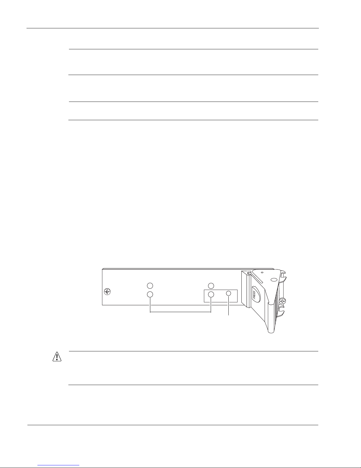
For any active or RAID-1 synchronized hard-disk drive, you must use the hot swap button,
shown in Figure 4, before you remove or replace a hard-disk drive without shutting the appliance
down. If you replace or remove drives with the IP1280 shut off, the RAID firmware will lose
track of RAID volume data. For information about how to remove and replace a hard-disk drive,
see “Installing or Replacing Hard-Disk Drives” on page 88.
Hard-Disk Drive LEDs
The hard-disk drive LEDs are located on the front panel of each hard-disk drive, as shown in
Figure 4. The LEDs provide the status of the hard-disk drives as described in Table 4.
Figure 4 Hard-Disk Drive Front Pane
l
To avoid damage to the ejector and locking lever, loosen the two retaining screws
before you remove the hard-disk drive. Once screw is located behind the ejector and
locking lever, and the other screw is on the opposite side.
22 IP1280 Security Platform Installation Guide
Page 23

Check Point IP1280 Security Platform Overview
Note
Table 4 Hard-Disk Drive LEDs
LED LED State Meaning
Activity Off No current disk activity.
Blinking green Current disk activity.
Status Solid red Hard-disk drive is turned on but is malfunctioning.
Solid green Hard-disk drive is turned on and is functioning.
Off One of the following:
• The hard-disk drive failed its test and was powered off.
• The hard-disk drive is ready to be removed using the hot
swap feature.
Blinking green One of the following:
• The system is booting up.
• The hard-disk drive is starting up.
• The system is testing the hard-disk drive.
Do not remove the hard-disk drive if the Status LED is blinking green or if the Hot Swap Ready LED is not illuminated
solid blue.
IP1280 Security Platform Installation Guide 23
Page 24
1 Overview
700W AC
FAULT
OVER
TEMP
PWR OK
00623
700W AC
FAULT
OVER
TEMP
PWR OK
Power cord receptacle
Power switches
Power supplies
Fan unit
Status LEDs
00624
700W AC
FAULT
OVER
TEMP
PWR OK
+
—
700W AC
FAULT
OVER
TEMP
PWR OK
+
—
Power connections
Power switches
Power supplies
Fan unit
Status LEDs
Power Supplies and Fan Unit
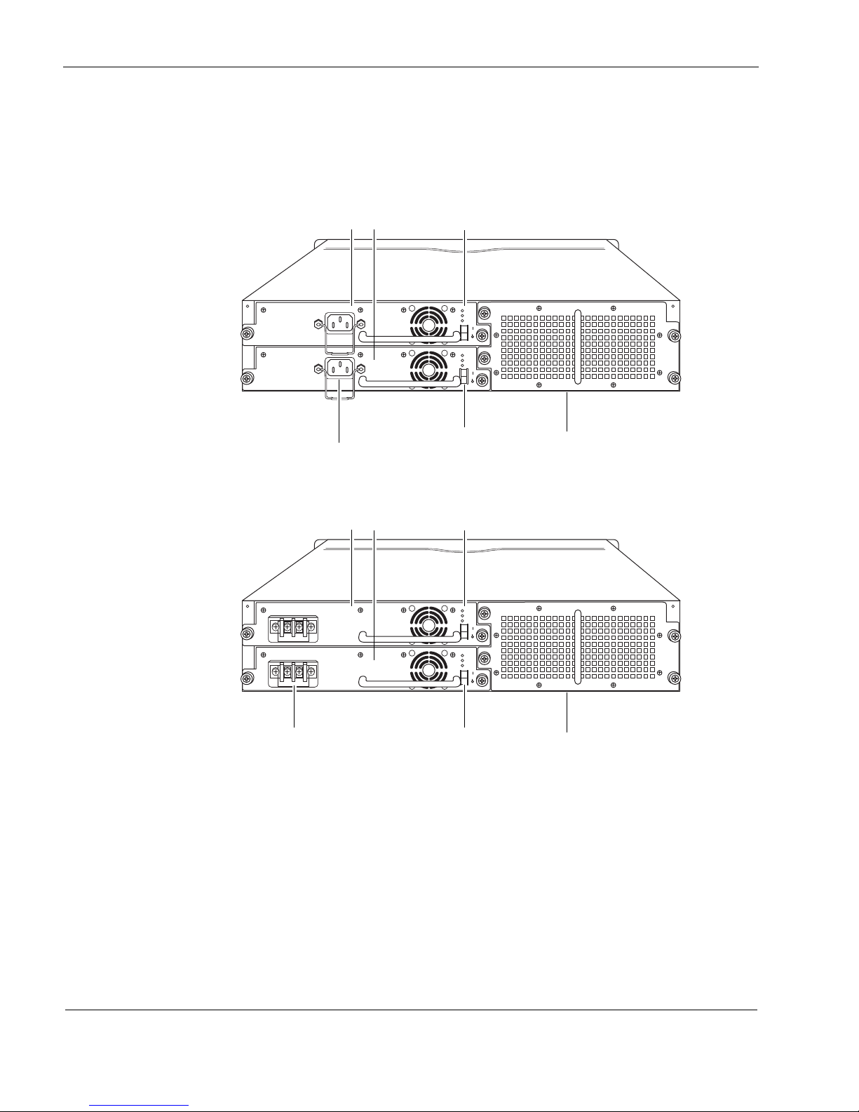
The power supplies and fan unit are located at the rear of the IP1280 appliance, as shown in
Figure 5 and Figure 6.
Figure 5 Power Supply and Fan Unit Locations (AC version)
Figure 6 Power Supply and Fan Unit Locations (DC version)
Power Supplies
The Check Point IP1280 appliance supports up to two power supplies for power sharing and
redundancy. The IP1280 comes with two power supplies as the standard package. The power
supplies are hot swappable and perform load sharing while two active power supplies are
installed, increasing the life of the power supplies.
24 IP1280 Security Platform Installation Guide
Page 25

Check Point IP1280 Security Platform Overview
Note
Note
On an appliance with two active power supplies installed, both power supplies should be
turned on for load sharing and redundancy. If both power supplies are not turned on, the
Fault LED illuminates. For more information about the power supply status LEDs, see
“Power Supply Status LEDs” on page 25.
The AC power supplies are autosensing and can accept input voltages between 85 VAC and 264
VAC. The power supply output is regulated to a tolerance of ± 5 percent of the specified output
voltage.
For information about how to install or remove and replace a failed power supply, see “Installing
or Replacing a Power Supply” on page 115.
DC Power Supplies
Do not use a combination of one AC power supply and one DC supply. Your IP1280 does
not work with such a configuration.
For IP1280 appliances that use DC power supplies, the following specifications apply for Check
Point approved components:
Input voltage:
-48 volts DC nominal
Voltage/Current range:
-40VDC/20A and -60VDC/13A
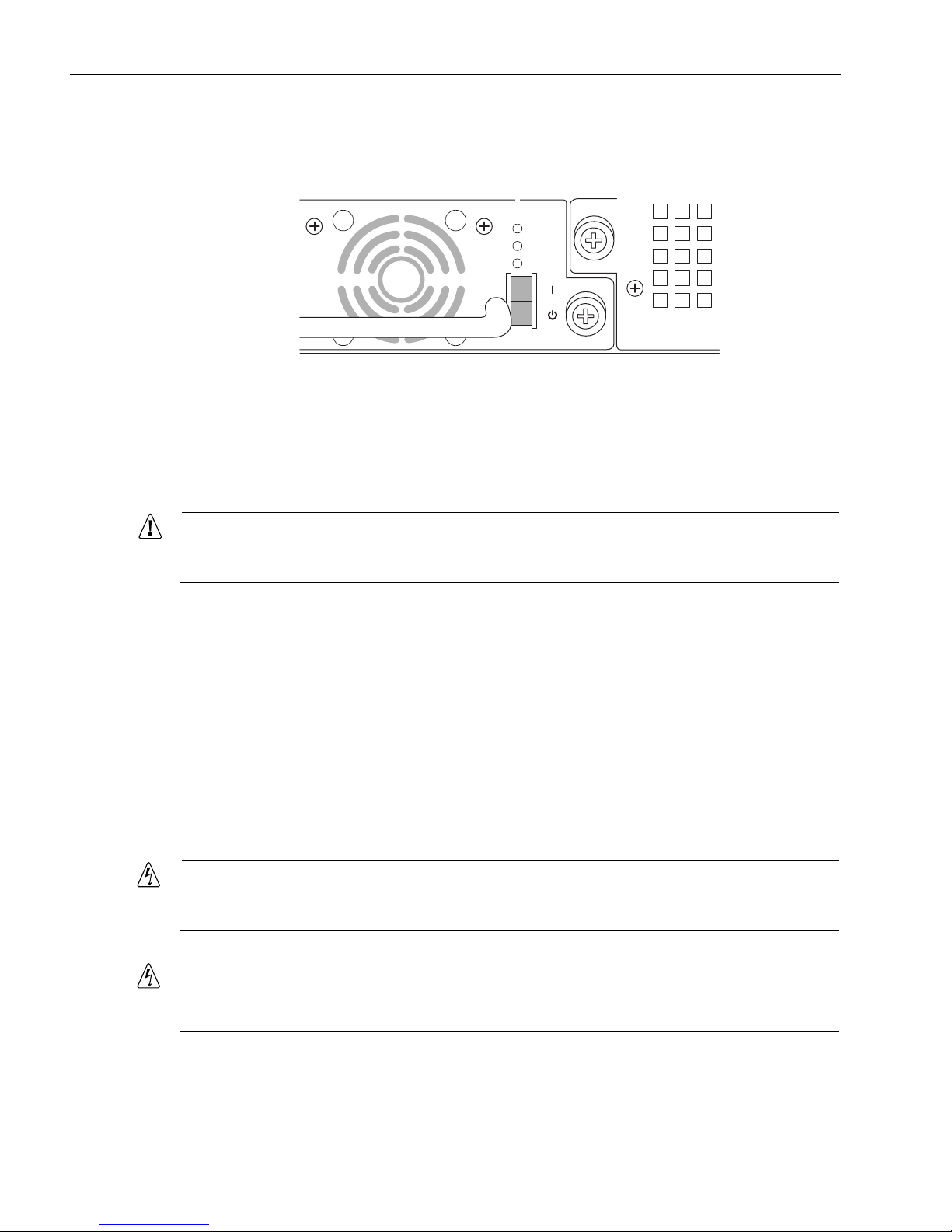
Power Supply Status LEDs
The power supply status LEDs provide the status of the power supplies as described in Table 5.
Table 5 Power Supply Status LEDs
LED LED status Meaning
Fault Red Power supply has a voltage problem and power was turned
off.
or
One power supply in a redundant system is not turned on.
Over Temp Yellow Power supply has an internal temperature problem. All
power to the unit is turned off. After the internal temperature
returns to normal, power will be turned back on.
PWR OK Green Power is on and the power supply is functioning properly.
IP1280 Security Platform Installation Guide 25
Page 26
1 Overview
Caution
Warning
Warning
FAULT
OVER
TEMP
PWR OK
00625
Status LEDs
Figure 7 Power Supply Status LED Location
Fan Unit
The IP1280 appliance fan unit is a single unit made up of eight individual fans to provide the air
flow required to maintain a proper operating temperature. The fan unit can provide proper
airflow for a short time even if an individual fan fails.
If an individual fan fails, replace the fan unit as soon as possible. For information about
how to replace a failed fan unit, see “Installing or Replacing a Fan Unit” on page 113.
The system status LEDs on the front panel of the appliance show the status of the fan unit. For
more information about the system status LEDs, see “System Status LEDs” on page 19.
Site Requirements
Before you install an IP1280 appliance, ensure that your computer room or wiring closet
conforms to the environmental specifications listed in Appendix A, “Technical Specifications.”
Safety Warnings and Cautions
Hazardous radiation exposure can occur if you use controls, make performance
adjustments, or follow procedures that are not described in this document.
To reduce the risk of fire, electric shock, and injury when you use telephone equipment,
follow basic safety precautions. Do not use the product near water.
26 IP1280 Security Platform Installation Guide
Page 27

Software Requirements
Warning
Warning
Caution
Caution
Note
Note
On IP1280 intended for shipment outside of the United States, the cord set might be
optional. If a cord set is not provided, use a power cord rated at 10A, 250V, maximum 15
feet long, made of HAR cordage and IEC fittings approved by the country of end use.
Replacement of fuses replaceable only by service personnel.
Replace the battery only with the same or equivalent type battery recommended by the
manufacturer. Dispose of used batteries according to the manufacturer's instructions.
Do not block any of the ventilation holes on the appliance. The components might
overheat and become damaged.
A readily accessible disconnect device shall be incorporated in the building installation
wiring.
Installation instructions indicate listed circuit breaker or branch rated fuse, rating, number of
poles, and special characteristics.
Software Requirements
Table 6 and Table 7 describe operating system and applications requirements for the Check Point
IP1280 appliances.
Table 6 Check Point IP1280 Disk-Based Security Platform Software Requirements
Check Point
Platform
Check Point
IP1280
IPSO Version Software
v4.2 or later Check Point VPN-1 versions compatible with the version of Check
Point IPSO you are using
IP1280 Security Platform Installation Guide 27
Page 28

1 Overview
Table 7 Check Point IP1280 Flash-Based Security Platform Software Requirements
Check Point
Platform
IPSO Version Software
Check Point
IP1280
For information about updates to the software requirements or additional applications that have
become available since this guide was published, see the Check Point Support Center at at http:/
/support.checkpoint.com/.
Product Disposal
v4.2 or later Check Point VPN-1 versions compatible with the version of Check
Point IPSO you are using
This symbol on the product or on its packaging indicates that this product must not
be disposed of with your other household waste. Instead, it is your responsibility to
dispose of your waste equipment by handing it over to a designated collection point
for the recycling of waste electrical and electronic equipment. The separate
collection and recycling of your waste equipment at the time of disposal will help to
conserve natural resources and ensure that it is recycled in a manner that protects
human health and the environment. For more information about where you can drop
off your waste equipment for recycling, please contact your local city office or your
household waste disposal service.
28 IP1280 Security Platform Installation Guide
Page 29

2 Installing the Check Point IP1280
Caution
Note
Appliance
This chapter describes how to install the Check Point IP1280 appliance. The following topics are
discussed:
Rack Mounting the Appliance
Before You Begin
To help guard against electrostatic discharge damage, make sure you are properly
grounded by using a grounding wrist strap and following the instructions provided with
the wrist strap before you handle the components or open the appliance. The
grounding plug on the front of the appliance (shown in Figure 1 on page 17) provides a
chassis grounding point If you do not have a grounding wrist strap, make sure you are
properly grounded before you touch any electronic component.
Rack Mounting the Appliance
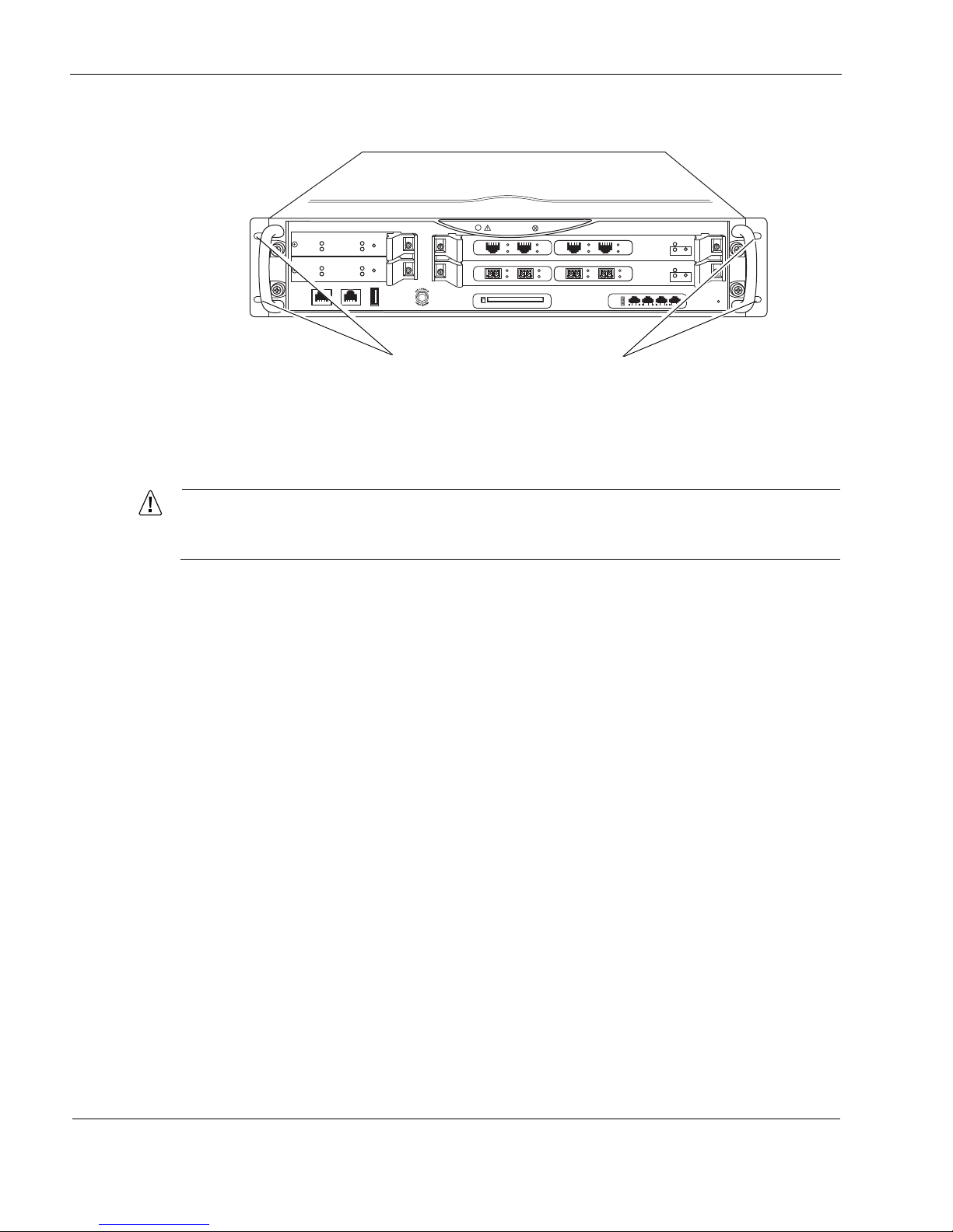
The Check Point IP1280 appliance mounts in a standard 19-inch equipment rack with four
mounting screws, as Figure 8 shows. Optional rear-mounting brackets are included with your
appliance shipment.
To avoid damaging your equipment, Check Point recommends that you use all four front
rack-mounting bolts when you install your appliance on the rack.
Check Point IP1280 Security Platform Installation Guide 29
Page 30
2 Installing the Check Point IP1280 Appliance
Caution
IP1280
RESET
00616a.1
CONSOLE AUX AUX2
HDD B
SLOT 3
SLOT 2
SLOT 1
HDD A
HOT SWAP
HOT SWAP
POWER
ACTIVITY
HARD DRIVE
STATUS
HOT SWAP
HOT SWAP
POWER
ACTIVITY
HARD DRIVE
STATUS
SLOT 4
1000BaseT
PC CARD
1
2
3
4
SUB SLOT 1 SUB SLOT 2
POWER
READY REQUEST
HOT SWAP
FIO CARRIER
1000B-LX
ACT
LINK
SUB SLOT 1 SUB SLOT 2
POWER
READY REQUEST
HOT SWAP
FIO CARRIER
1000B-LX
ACT
LINK
V2
1000BaseT
ACT
LINK
ACT
LINK
V2
1000BaseT
ACT
LINK
ACT
LINK
Rack-mounting screw locations
Figure 8 Front Rack-Mounting Screw Locations
Two front rack-mounting positions allow you to mount the appliance either flush with the rack,
or four inches forward of the equipment rack. If the space behind the rack is insufficient, the rack
mounting brackets can be attached further back on the side of the appliance.
During installation, do not block any ventilation openings. Doing so might result in
damage to the appliance when it is turned on.
Before You Begin
To rack-mount the appliance, you need:
Phillips-head screwdriver
Disposable grounding wrist strap
Suitable, grounded work surface on which to place the chassis tray assembly
30 Check Point IP1280 Security Platform Installation Guide
Page 31
Before You Begin
Note
Note
or
00646
Secure grounding-cable lug to rack or
other appropriate grounding location
with 1/4-inch screw and kep washer
Attach cable lug to
side of appliance with
two 10-32 screws
Grounding cable
Grounding lug can be positioned
either vertically or horizontally
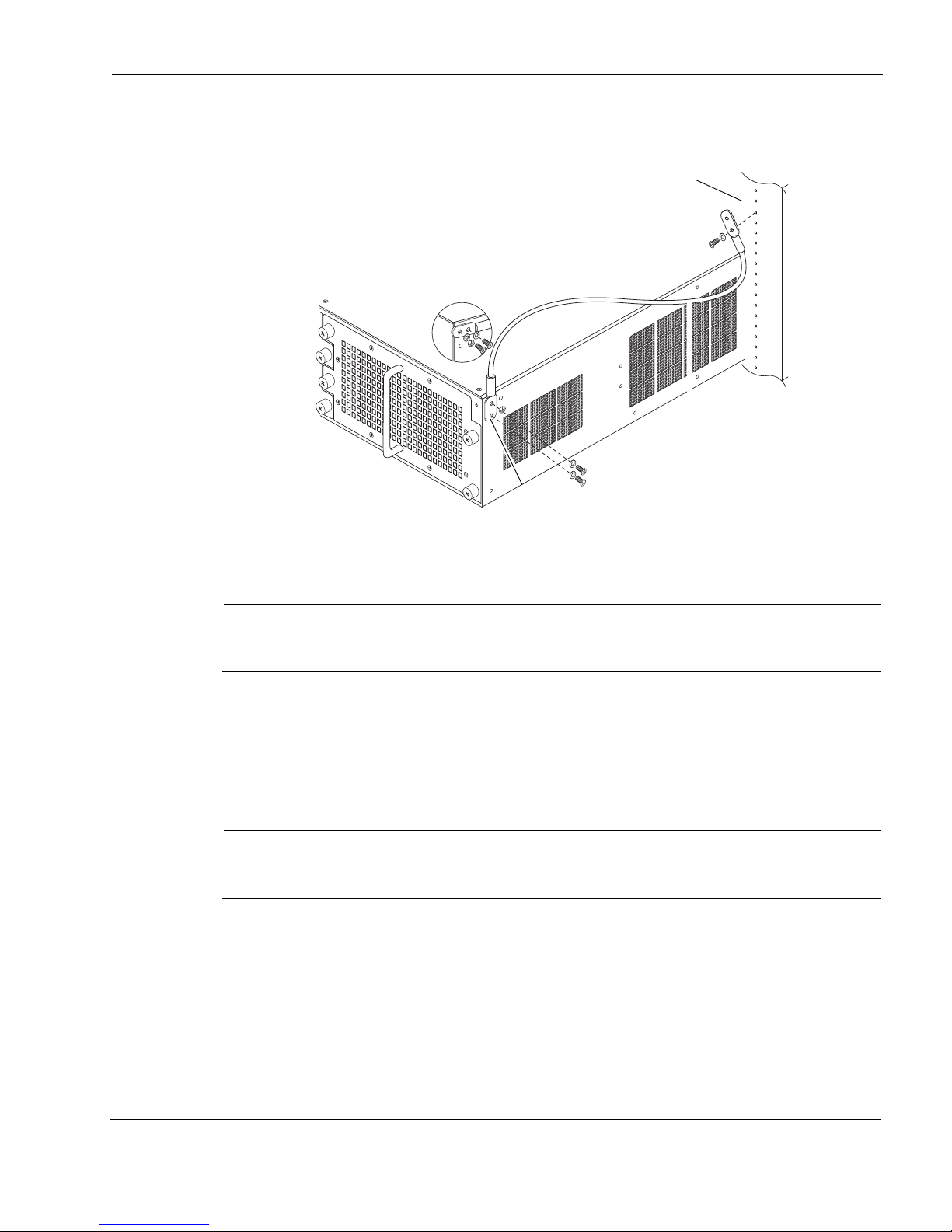
Before you rack mount the appliance, you can ground it by using the grounding lugs provided.
To ground your IP1280 appliance
Consult your company policy to determine the equipment grounding procedure that you use
with this unit installation.
1. Put on the wrist strap and attach the free end to the wrist-strap jack to the ESD grounding
2. Secure one end of the grounding cable to the side of the appliance either vertically or
The green/yellow insulated copper ground connector should be a minimum of #12 AWG
(minimum 2.5 mm2 cross-sectional areas).
3. Use the 1/4-inch screw and kep washer included with the appliance or gateway to attach the
plug on the front of the appliance.
horizontally, as shown in the figure, with the two 10-32 screws and kep washers included in
the grounding cable kit. Torque the screws to 80 inch ounces.
other end of the cable to the appliance or gateway rack-mount hardware (or other
appropriate earth ground location that meets the specifications of your installation site) with
the kep washer between the screw and cable lug. Torque the screw to 384 inch ounces
Check Point IP1280 Security Platform Installation Guide 31
Page 32
2 Installing the Check Point IP1280 Appliance
Caution
700W AC
FAULT
OVER
TEMP
PWR OK
00623
700W AC
FAULT
OVER
TEMP
PWR OK
Fan unit
00631
7
0
0
W
A
C
FAULT
OVER
TEMP
PWR OK
7
0
0
W
A
C
FAULT
OVER
TEMP
PWR OK
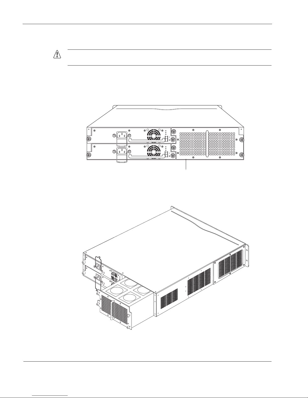
To rack mount the appliance
The appliance is heavy. Carefully remove it from the packaging.
1. Remove the appliance from the packaging.
2. Optionally, remove the fan unit from the back of the appliance.
a. Locate the fan unit and the four retaining screws that secure it on the back of the IP1280.
b. Loosen the retaining screws by turning them counterclockwise.
c. Slowly pull the fan unit out of the chassis tray assembly toward the rear.
32 Check Point IP1280 Security Platform Installation Guide
Page 33
Before You Begin
700W AC
FAULT
OVER
TEMP
PWR OK
00623
700W AC
FAULT
OVER
TEMP
PWR OK
Power supplies
00630
7
0
0
W
A
C
FA
ULT
OVER
TEMP
PWR OK
7
0
0
W
A
C
FAULT
OVER
TEMP
PW
R O
K
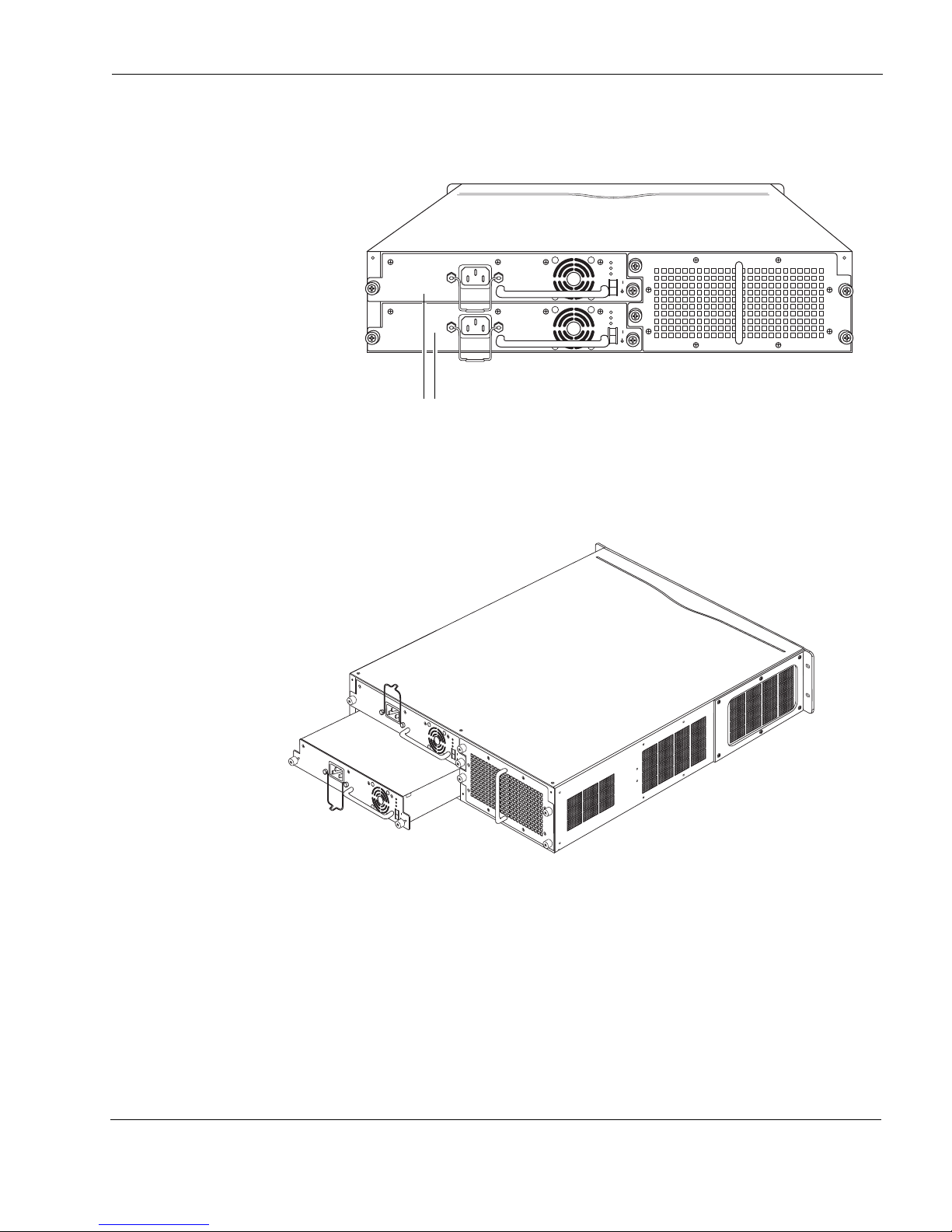
3. Optionally, remove the power supplies from the rear of the appliance.
a. Locate the power supply on the back of the IP1280 and the two screws that secure it.
b. Remove the two retaining screws.
c. Remove the grounding lugs.
d. Use the handles to gently pull the power supply out of the chassis tray assembly.
4. Optionally, remove the chassis tray assembly from the appliance.
Check Point IP1280 Security Platform Installation Guide 33
Page 34
2 Installing the Check Point IP1280 Appliance
Caution
IP1280
RESET
00616a.1
CONSOLE AUX AUX2
HDD B
SLOT 3
SLOT 2
SLOT 1
HDD A
HOT SWAP
HOT SWAP
POWER
ACTIVITY
HARD DRIVE
STATUS
HOT SWAP
HOT SWAP
POWER
ACTIVITY
HARD DRIVE
STATUS
SLOT 4
1000BaseT
PC CARD
1
2
3
4
SUB SLOT 1 SUB SLOT 2
POWER
READY REQUEST
HOT SWAP
FIO CARRIER
1000B-LX
ACT
LINK
SUB SLOT 1 SUB SLOT 2
POWER
READY REQUEST
HOT SWAP
FIO CARRIER
1000B-LX
ACT
LINK
V2
1000BaseT
ACT
LINK
ACT
LINK
V2
1000BaseT
ACT
LINK
ACT
LINK
Chassis tray assembly screws
IP1280
RESET
C
O
N
S
O
L
E
A
U
X
A
U
X
2
H
D
D
B
S
L
O
T
3
S
L
O
T
2
S
L
O
T
1
H
D
D
A
HOT SWAP
H
O
T
S
W
A
P
P
O
W
E
R
A
C
T
I
V
I
T
Y
H
A
R
D
D
R
I
V
E
S
T
A
T
U
S
HOT SWAP
H
O
T
S
W
A
P
P
O
W
E
R
A
C
T
I
V
I
T
Y
H
A
R
D
D
R
I
V
E
S
T
A
T
U
S
S
L
O
T
4
00637a
1000BaseT
1
2
3
4
SUB SLOT 1
SUB SLOT 2
POWER
READY
REQUEST
HOT SWAP
FIO CARRIER
1000B-LX
A
CT
LINK
SUB SLOT 1
SUB SLOT 2
POWER
READY
REQUEST
HOT SWAP
FIO CARRIER
1000B-LX
ACT
LINK
V2
1000BaseT
A
C
T
L
I
N
K
A
C
T
L
I
N
K
V2
1000BaseT
A
C
T
L
I
N
K
A
C
T
L
I
N
K
To help guard against electrostatic discharge damage, make sure you are properly
grounded by using a grounding wrist strap and following the instructions provided with
the wrist strap before you handle the components or open the appliance. The
grounding plug on the front of the appliance (shown in Figure 1 on page 17) provides a
chassis grounding point. If you do not have a grounding wrist strap, make sure you are
properly grounded before you touch any electronic component.
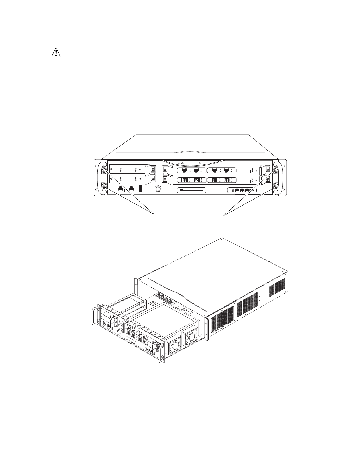
a. Loosen the four chassis tray assembly retaining screws from the front panel of the
appliance.
b. Slide the chassis tray assembly forward and pull it entirely out of the appliance.
c. Place the chassis tray assembly on a properly grounded surface.
5. Adjust the front mounting brackets on the side of the appliance if necessary.
34 Check Point IP1280 Security Platform Installation Guide
Page 35
Before You Begin
00554a
Apply 160 inch ounces of
torque when you secure the
two mounting screws
6. Mount the appliance into a standard 19-inch rack by using four standard rack mounting
screws.
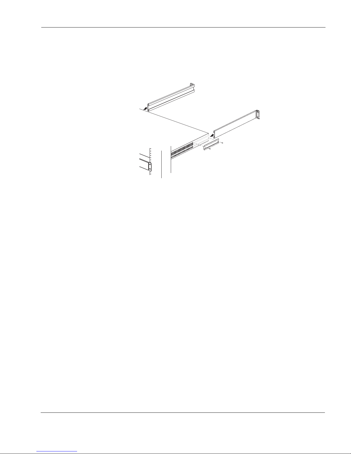
7. Optionally, you can install the rear mounting brackets included with your appliance as
shown in the following figure.
8. Slide the chassis tray assembly back into the appliance until it clicks into place, and resecure
the four chassis tray assembly retaining screws.
9. Reinstall the fan unit into the rear of the appliance.
10. Reinstall the power supplies.
Check Point IP1280 Security Platform Installation Guide 35
Page 36

2 Installing the Check Point IP1280 Appliance
36 Check Point IP1280 Security Platform Installation Guide
Page 37

3 Performing the Initial Configuration
Note
The first time you turn on power to a Check Point IP1280 appliance, the initial configuration
process begins. This process enables you to configure the network settings and provides access
to the admin account.
You can perform the initial configuration in two ways:
Configure a DHCP server to provide the initial configuration information the first time the
appliance is started.
Perform the initial configuration manually by using a console connection.
This chapter describes how to perform the initial configuration manually by using a console
connection. It includes the following sections:
Using a Console Connection
Connecting Power and Turning the Power On
Performing the Initial Configuration
Connecting Network Interfaces
Using Check Point Network Voyager
Using the Command-Line Interface
Using Check Point Horizon Manager
For information about how to use the DHCP client for initial configuration, see the Read Me
First document, Using DHCP to Configure Your Appliance, included with the appliance.
Check Point recommends that you physically install all network interface cards (NICs),
Accelerated Data Path (ADP) services modules, and other hardware components before
you perform the initial configuration procedure this chapter describes. For information about
how to install NICs and ADP modules, see Chapter 4, “Installing and Replacing Network
Interface Cards and ADP Services Modules.” For information about how to install other
components, see Chapter 7, “Installing and Replacing Components Other than Network
Interface Cards (NICs) and Accelerated Data Path (ADP) Services Modules.”
Check Point IP1280 Security Platform Installation Guide 37
Page 38
3 Performing the Initial Configuration
Note
IP1280
RESET
00616a.1
CONSOLE AUX AUX2
HDD B
SLOT 3
SLOT 2
SLOT 1
HDD A
HOT SWAP
HOT SWAP
POWER
ACTIVITY
HARD DRIVE
STATUS
HOT SWAP
HOT SWAP
POWER
ACTIVITY
HARD DRIVE
STATUS
SLOT 4
1000BaseT
PC CARD
1
2
3
4
SUB SLOT 1 SUB SLOT 2
POWER
READY REQUEST
HOT SWAP
FIO CARRIER
1000B-LX
ACT
LINK
SUB SLOT 1 SUB SLOT 2
POWER
READY REQUEST
HOT SWAP
FIO CARRIER
1000B-LX
ACT
LINK
V2
1000BaseT
ACT
LINK
ACT
LINK
V2
1000BaseT
ACT
LINK
ACT
LINK
Console port
Using a Console Connection
If you do not use DHCP to perform the initial configuration of your Check Point IP1280
appliance, you must use a serial console connection (cable included). After you perform the
initial configuration, you no longer need the console connection.
You can use any standard VT100-compatible terminal with an RS-232 data terminal equipment
(DTE) interface or terminal-emulation program configured with the following settings for the
console:
9600 bps
8 data bits
No parity
1 stop bit
To connect to the console
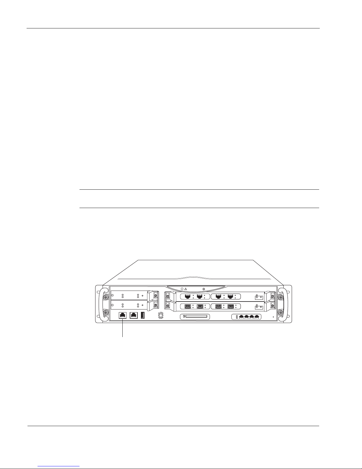
1. Connect the supplied null-modem cable (console cable) to the console port on the front
panel of the IP1280 appliance.
The supplied console cable is Cisco compatible.
Use only the DB9 port labeled Console on the front panel; the serial (AUX) port is an
auxiliary port.
If you connect the console port to a data communications equipment (DCE) device, use a
straight-through cable.
For cable pin assignments for the console connection, see “Console Port” on page 18.
2. Connect the other end of the cable to the VT100 console or to a system running a terminal-
emulation program.
38 Check Point IP1280 Security Platform Installation Guide
Page 39
Connecting Power and Turning the Power On
Caution
Note
700W AC
FAULT
OVER
TEMP
PWR OK
00623
700W AC
FAULT
OVER
TEMP
PWR OK
Power cord receptacles
Power switch
Power supplies
Connecting Power and Turning the Power On
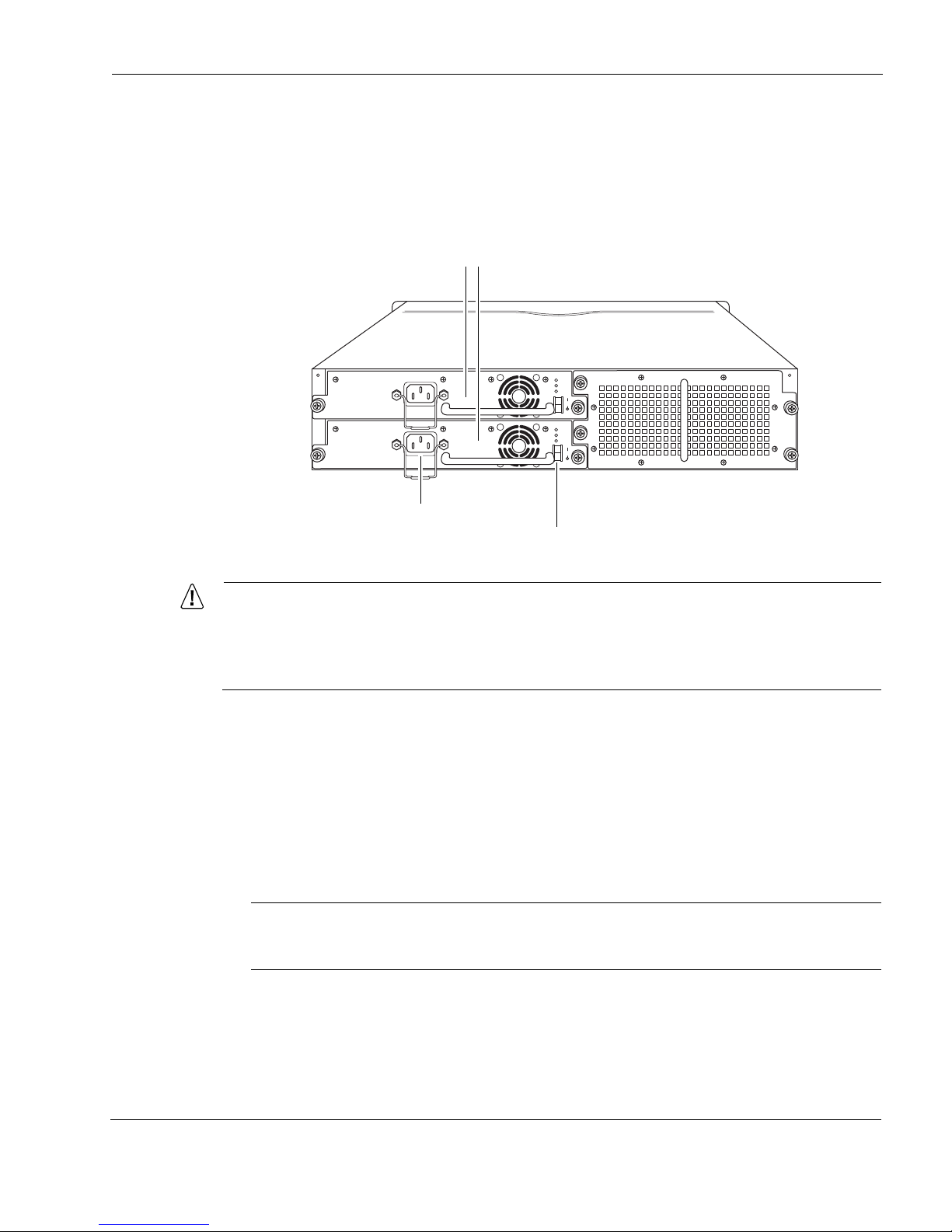
A power switch and a receptacle for the power cord are located on each power supply on the
back of the appliance as shown in Figure 9.
Figure 9 Power Switch Location
To avoid potential service interruptions from momentary facility power interruptions and
potential power spikes that might damage your equipment, Check Point strongly
recommends that you use an uninterruptible power supply (UPS) with surge protection
with your IP1280 appliance.
To connect the power supply
1. Connect the power cord securely into the power cord receptacle on the power supply.
2. Plug the other end of the power cord into a three wire grounded power strip or wall outlet.
3. Toggle the 1/O power switch to the 1 position to provide power to the IP1280 appliance.
The fan unit on the power supply turns on when you press the power switch. Verify that the
power supply fans are running after you press the switch.
The IP1280 appliance power supply automatically detects the input voltage (115 VAC or
220 VAC [85 to 264]) and configures itself appropriately.
If the fans are not running, make sure:
The power cord is properly connected.
Check Point IP1280 Security Platform Installation Guide 39
Page 40

3 Performing the Initial Configuration
Note
Note
The power supply switch is on.
The chassis assembly is pushed all the way in from the front of the appliance.
That power is turned on to the power strip or wall receptacle into which you plugged the
appliance.
If the fans are still not running, contact your Check Point service provider or Check Point
Support Center at http://support.checkpoint.com/.
On an appliance with two active power supplies installed, connect and turn on both power
supplies for load sharing and redundancy. If two power supplies are installed and both
power supplies are not turned on, the Fault LED illuminates.
Performing the Initial Configuration
If you do not use DHCP to perform the initial configuration of your Check Point IP1280
appliance, you must use a serial console connection (cable included). After you perform the
initial configuration, you no longer need the console connection.
To perform the initial configuration
1. Turn on the appliance.
At the console a series of startup messages appears, then the following prompt appears:
Type any character to enter command mode.
The prompt remains on the screen for about five seconds. If you type any character during
this time, the system activates the Check Point IPSO boot manager.
For information about how to use the boot manager, see the Boot Manager Reference
Guide.
After some miscellaneous output appears, the following prompt appears:
Hostname?
If the Hostname? prompt does not appear on the console, check the console port and console
display connections to ensure that the serial cable is completely plugged in at both ends. If
you verify the console connections and still do not see either the BOOTMGR> or
Hostname? prompts, verify that the terminal or terminal emulator program settings are
correct. If the settings are correct, contact your Check Point service provider as listed in
“Check Point Contact Information” on page 2.
2. Respond to the Hostname? prompt within 30 seconds to prevent the DHCP client from
starting.
40 Check Point IP1280 Security Platform Installation Guide
Page 41

Performing the Initial Configuration
Note
If the DHCP client starts, it might configure the appliance with an incorrect host name and
IP address (this could happen if a DHCP server on your network is configured to respond to
any request). To reset the incorrect host name and IP address:
a. Establish a console connection to the appliance.
b. Log into the system using the user name admin and the password password.
c. Enter the following:
rm /config/active
or
mv /config/active /config/active.old
d. Reboot the appliance.
e. Respond to the Hostname? prompt within 30 seconds to prevent the DHCP client from
restarting.
3. At each subsequent prompt, enter the requested configuration information.
For more information about how to respond to the prompts during the initial configuration
process, see the release notes for the Check Point software release you are running.
4. When you are prompted to select an interface, Check Point recommends that you select one
of the Ethernet management interface ports.
To select an interface, enter the number adjacent to the physical ID in the list of connected
interfaces.
A physical ID identifies the NIC or ADP module interface type (interface_type) and
provides information about its slot number (slot_num), subslot number (subslot_num)
and port number (port_num). The physical ID syntax is:
interface_type-sslot_num/ssubslot_numpport_num
For example, the physical ID for the first port of a two-port Ethernet NIC in slot 1, subslot
2 would be:
eth-s1/s2p1
The Ethernet management interface ports are numbered eth-s4p1 through eth-s4p4.
After you complete the initial configuration, you can use Check Point Network Voyager to
configure the remaining network ports.
Check Point IP1280 Security Platform Installation Guide 41
Page 42

3 Performing the Initial Configuration
Note
Note
Connecting Network Interfaces
Connect at least one network interface to the network to use as the Check Point Network
Voyager system-management interface. This interface is configured during the initial
configuration process, which is described in Chapter 3, “Performing the Initial Configuration.”
You can also connect the remaining LAN interface cables at this point, although you are not
required to do so.
Check Point recommends that you use one of the four front-panel Ethernet management
ports for this connection.
To connect Ethernet devices, use a straight-through RJ-45 cable to connect to a hub.
For details, see “Ethernet NIC Connectors and Cables” on page 63.
To connect Gigabit Ethernet devices, use a fiber-optic cable with an LC connector for each
NIC or ADP module interface. The destination end of the cable can be either LC or SC,
depending on the type of connector required for the destination Gigabit Ethernet device.
For details, see “Fiber-Optic Gigabit Ethernet NIC Connectors and Cables” on page 65.
Using Check Point Network Voyager
Use Check Point Network Voyager to configure and monitor your appliance.
To open Check Point Network Voyager
1. Open a Web browser on the host you plan to use to configure or monitor your appliance.
2. In the Location or Address field, enter the IP address of the initial interface you configured
for the appliance.
You are prompted to enter the admin username and the password you entered when you
performed the initial configuration.
If the username login screen does not open, you might not have a physical network
connection between the host and your appliance, or you might have a network routing
problem. Confirm the information you entered during the initial configuration and check
that all cables are firmly connected. For more information, see the troubleshooting
section in the installation guide for your appliance.
42 Check Point IP1280 Security Platform Installation Guide
Page 43
Using Check Point Network Voyager
Link to complete user
documentation
Link to online help (context sensitive help)
Viewing Check Point IPSO Documentation by Using
Check Point Network Voyager
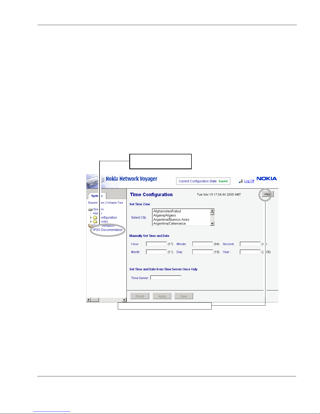
The following documentation is available from the Check Point Network Voyager interface, as
shown in Figure 10:
Network Voyager Reference Guide—This guide is the comprehensive reference source for
Check Point Network Voyager. To access this source, look at the list in the navigation tree on
the left side of the window (as shown in Figure 10).You can also access this guide and other
Check Point IPSO documentation at the Check Point Support Center at http://
support.checkpoint.com/.
Network Voyager online help—You can access online help when you use Check Point
Network Voyager. Online help is the context-sensitive information source for Check Point
Network Voyager
Close button is available at the bottom of each online help window you view.
Figure 10 Check Point Network Voyager Reference Access Points
. To access online help for the window you are viewing, click Help. A
Check Point IP1280 Security Platform Installation Guide 43
Page 44

3 Performing the Initial Configuration
Using the Command-Line Interface
You can also use the Check Point IPSO command-line interface (CLI) to manage and configure
Check Point IP security appliances from the command line. Nearly everything that you can
accomplish with Check Point Network Voyager you can also do with the CLI.
To access the command-line interface
1. Log on to the appliance by using a command-line connection (SSH, console, or Telnet) over
a TCP/IP network as an admin, cadmin, or monitor user:
If you log in as a cadmin (cluster administrator) user, you can change and view
configuration settings on all the cluster nodes. For information about how to administer a
cluster, see the traffic management commands section in the CLI Reference Guide for the
version of Check Point IPSO you are using.
2. If you log in as a monitor user, you can execute only the show form of commands. That is,
you can view configuration settings, but you cannot change them.
You can now execute CLI commands from the CLI shell and the Check Point IPSO shell. The
Check Point IPSO shell is what you see when you initially log on to the appliance.
Execute from To Implement Purpose
Check Point
IPSO command
line
Check Point
IPSO command
line
Command files From inside the CLI shell, enter
Enter the following command
to invoke the CLI shell:
clish
The prompt changes, and you
can then enter CLI commands.
Enter
clish -c
“cli-command”
load commands
filename
Enter any CLI commands in an
interactive mode with help text
and other helpful CLI features.
Execute a single CLI
command. You must place
double-quotation marks
around the CLI command.
Load commands from a text
file that contains commands.
The argument must be the
name of a regular file.
For more information about how to access and use the CLI, see the CLI Reference Guide for the
version of Check Point IPSO you are using.
Using Check Point Horizon Manager
Check Point Horizon Manager is an extension of the Check Point Network Voyager
management functionality.
While Check Point Network Voyager provides the device administrator access to network
configuration tasks (such as interface configuration and routing configuration) and security
44 Check Point IP1280 Security Platform Installation Guide
Page 45

Using Check Point Horizon Manager
configuration tasks (such as user configuration and access configuration), Check Point Horizon
Manager concentrates on secure software image, inventory, and platform management of Check
Point IP security platforms.
Using Check Point Horizon Manager, an administrator can obtain configuration information,
upgrade (or downgrade) the operating system, perform application installations, and distribute
necessary licensing to multiple platforms simultaneously, thereby reducing potential human
error and improving productivity.
Using Check Point Horizon Manager, a network security professional can manage multiple
devices simultaneously, perform parallel software upgrades, device verifications, device
configuration, file backups, and more.
Check Point Horizon Manager is designed to manage and configure a large number of Check
Point IP security appliances that reside on a corporate enterprise, managed service provider
(MSP), or hosted applications service provider network (ASP).
For information about how to obtain Check Point Horizon Manager or to learn more about the
Check Point Horizon Manager, see the Check Point Web site at www.checkpoint.com.
Check Point IP1280 Security Platform Installation Guide 45
Page 46

3 Performing the Initial Configuration
46 Check Point IP1280 Security Platform Installation Guide
Page 47

4 Installing and Replacing Network
Note
Caution
Interface Cards and ADP Services
Modules
The Check Point IP1280 appliance may come with one of the network interface cards (NICs) or
Accelerated Data Path (ADP) services modules that you ordered already installed. NICs or ADP
modules installed in IP1280 slots 1 and 2 are housed in a 6U PMC carrier. NICs housed in 6U
PMC carriers are hot swappable, but NICs in slots 3 and 4 and ADP modules are not, and you
must power down your appliance to install or replace them.
ADP modules are used only in slot 1 or 2.
This chapter describes the following topics:
Removing, Installing, and Replacing NICs and ADP Modules
To remove and install 6U card carriers or ADP modules, and to replace network interface
cards (NICs) in PMC carriers
To replace a network interface card (NIC) in slot 3 or 4
Configuring and Activating Interfaces
Monitoring Network Interface Cards or ADP Modules
For detailed information about specific network interface cards, see
Chapter 5, “About IP1280 Appliance Network Interface Cards.”
You should have a working knowledge of networking equipment before you attempt to
service an IP1280. Limit service of the appliance to the procedures described in this
chapter.
Check Point IP1280 Security Platform Installation Guide 47
Page 48

4 Installing and Replacing Network Interface Cards and ADP Services Modules
Caution
Note
Note
Note
To help guard against electrostatic discharge damage, make sure you are properly
grounded by using a grounding wrist strap and following the instructions provided with
the wrist strap before you handle the components or open the appliance. The
grounding plug on the front of the appliance (shown in Figure 1 on page 17) provides a
chassis grounding point. If you do not have a grounding wrist strap, make sure you are
properly grounded before you touch any electronic component.
Removing, Installing, and Replacing NICs and ADP
Modules
IP1280 appliances have two slots on the front of the appliance that hold two 6U PMC carriers or
ADP modules. You must first remove the 6U PMC carrier or ADP module from its slot before
you can remove or install a NIC or ADP module. You must also remove both PMC carriers or
ADP modules to install or replace NICs in slot 3 or 4.
To install or replace ADP modules, you only need to refer to the steps related to removing and
installing 6U PMC carriers in this section, but you also need to refer to Chapter 6, “About
IP1280 Appliance ADP Services Modules.”
Check Point recommends that you distribute installed NICs equally across the 6U PMC
carriers. For example, if you install only two NICs, put one in each carrier. As you add NICs,
fully load the 6U carriers before you install NICs in slots 3 and 4.
Because the IP1280 supports hot swapping of NICs, you do not have to turn off power from
the system to remove, install, or replace a NIC. You cannot, however hot swap ADP
modules.
Before You Begin
Before you install a NIC, make sure that the rubber gasket around the front of the NIC is
installed properly.
To remove, install, or replace a NIC or ADP module, you need the following:
Phillips-head screwdriver
48 Check Point IP1280 Security Platform Installation Guide
Page 49
Removing, Installing, and Replacing NICs and ADP Modules
Note
Note
Caution
Hot swap button
and hot swap LED
For slots 1 and 2, a suitable, grounded work surface on which to place the PMC carrier or
ADP module
Replacement or new NIC or ADP module
If you are servicing the slot 1 carrier or ADP module, Check Point recommends that you
disconnect interface cables from the ports after you remove the carrier, as it is more difficult
to remove cables from a carrier or ADP module installed in that location.
To remove and install 6U card carriers or ADP modules, and to replace network
interface cards (NICs) in PMC carriers
1. Identify the location (PMC carrier and slot) of the NIC or ADP module to be replaced.
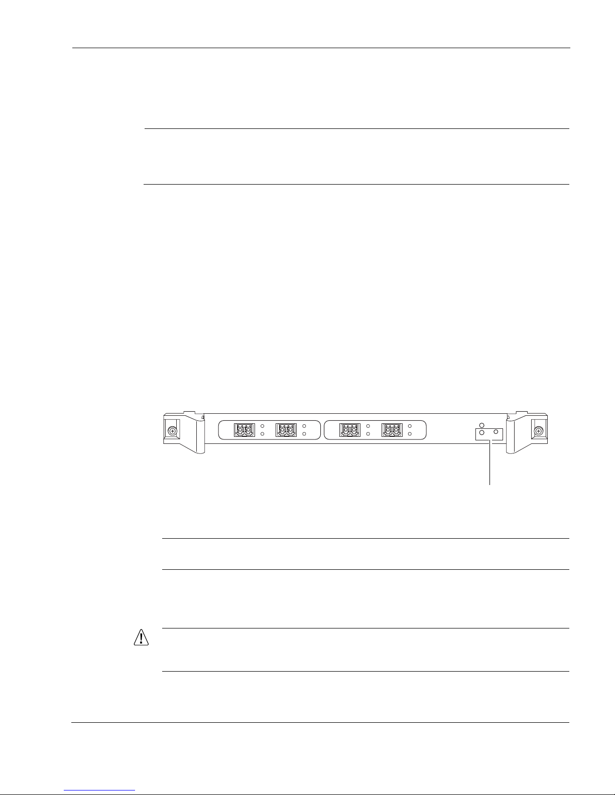
2. To replace a PMC carrier, press the hot swap button on the PMC carrier with an open paper
clip or similar device and wait for the hot swap LED to illuminate solid blue.
To replace an ADP module, do the following:
a. Use Check Point Network Voyager or the CLI to perform an orderly shutdown of the
IP1280.
For information about how to access Check Point Network Voyager and the related
reference materials, see “Using Check Point Network Voyager” on page 44.
b. Press the power switches, located on each power supply at the back of the appliance, to
turn off power to the appliance.
SUB SLOT 1 SUB SLOT 2
1000B-LX
LINK
ACT
1000B-LX
Hot swap is not supported for ADP modules.
LINK
ACT
POWER
FIO CARRIER
HOT SWAP
READY REQUEST
00661
3. Loosen the screws on each side of the PMC carrier or ADP module. The screws are located
behind the ejector and locking levers.
To avoid damage to the ejector and locking lever, loosen the retaining screw behind
each ejector and locking lever before you remove the PMC carrier or ADP module.
Check Point IP1280 Security Platform Installation Guide 49
Page 50
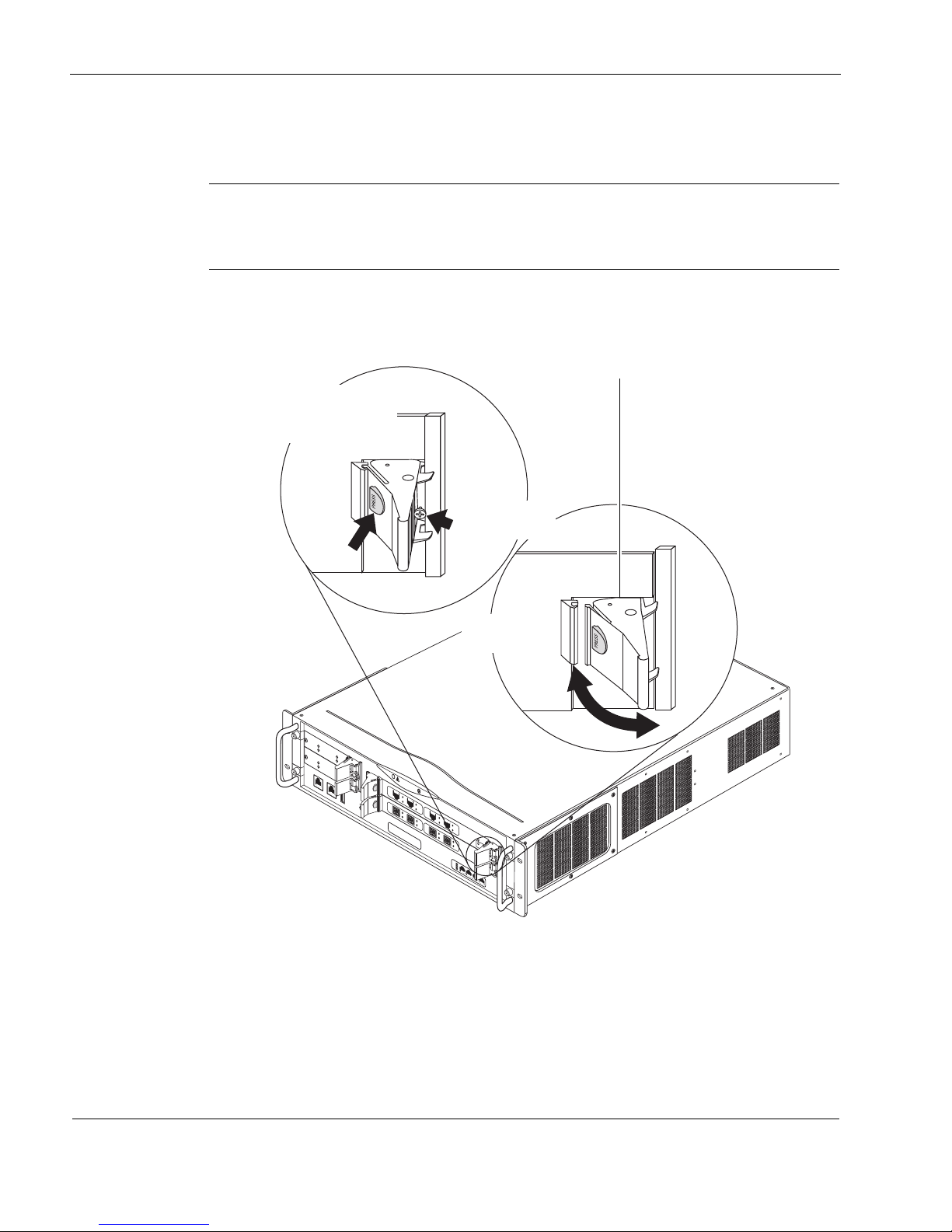
4 Installing and Replacing Network Interface Cards and ADP Services Modules
Note
00645a
I
P
1
2
8
0
RES
ET
C
O
N
S
O
L
E
A
U
X
A
U
X
2
H
D
D
B
S
L
O
T
3
S
L
O
T
2
S
L
O
T
1
H
D
D
A
HOT SWAP
H
O
T
S
W
A
P
P
O
W
E
R
A
C
T
I
V
I
T
Y
H
A
R
D
D
R
I
V
E
S
T
A
T
U
S
S
L
O
T
4
H
O
T
S
W
A
P
P
O
W
E
R
A
C
T
I
V
I
T
Y
H
A
R
D
D
R
I
V
E
S
T
A
T
U
S
1000BaseT
1
2
3
4
SUB SLOT 1
SUB SLOT 2
POWER
READY
REQUEST
HOT SWAP
FIO CARRIER
1000B-LX
AC
T
L
I
NK
SUB SLOT 1
SUB SLOT 2
POWER
READY
REQUEST
HOT SWAP
FIO CARRIER
1000B-LX
A
C
T
L
I
NK
V2
1000BaseT
ACT
LINK
ACT
LINK
V2
1000BaseT
ACT
LINK
ACT
LINK
Ejector and locking levers
Push red button to
disengage or
engage lock
Unscrew screw
to release
Release or lock
into place
4. Press the red buttons on the ejector and locking levers on the PMC carrier or ADP module.
The lock is released.
Pressing both red buttons on the front of the ejector and locking levers disengages the
lock and removes power from the PMC carrier or ADP module. The power LED on the
front of the PMC carrier turns off when the power is removed.
5. Press or push the levers toward the outer edges of the IP1280.
6. Continue to press or push the levers outward until the PMC carrier or ADP module is
released and extends slightly beyond the front panel of the IP1280.
50 Check Point IP1280 Security Platform Installation Guide
Page 51
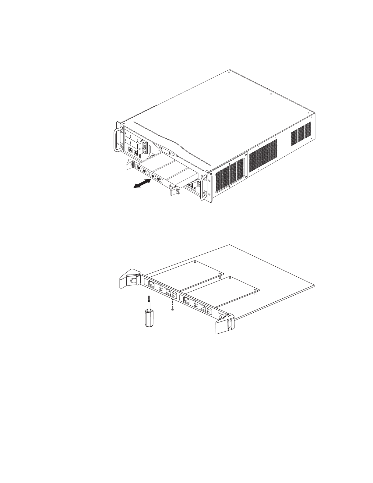
Removing, Installing, and Replacing NICs and ADP Modules
Note
00643a
I
P
1
2
8
0
RE
S
ET
C
O
N
S
O
L
E
A
U
X
A
U
X
2
H
D
D
B
S
L
O
T
3
S
L
O
T
2
S
L
O
T
1
H
D
D
A
HOT SWAP
H
O
T
S
W
A
P
P
O
W
E
R
A
C
T
I
V
I
T
Y
H
A
R
D
D
R
I
V
E
S
T
A
T
U
S
A
C
T
S
T
A
T
S
L
O
T
4
H
O
T
S
W
A
P
P
O
W
E
R
A
C
T
I
V
I
T
Y
H
A
R
D
D
R
I
V
E
S
T
A
T
U
S
1000BaseT
1
2
3
4
1000B-LX
A
C
T
L
I
N
K
1000B-LX
A
C
T
L
I
N
K
V2
S
U
B
S
L
O
T
1
S
U
B
S
L
O
T
2
P
O
W
E
R
R
E
A
D
Y
R
E
Q
U
E
S
T
H
O
T
S
W
A
P
F
I
O
C
A
R
R
I
E
R
V2
1000BaseT
A
C
T
L
I
N
K
A
C
T
L
I
N
K
V2
1000BaseT
A
C
T
L
I
N
K
A
C
T
L
I
N
K
00311
7. Gently pull the PMC carrier or ADP module out from the slot and place it on a suitable,
grounded work surface.
8. Locate the bezel retaining screws, used to keep the NIC attached, on the underside of the
PMC carrier.
9. Remove the two bezel retaining screws with a Phillips screwdriver.
If you are installing a NIC in an unoccupied slot on the PMC carrier, remove the blank
bezel that covers the slot and retain it for future use. Proceed to step 12.
Check Point IP1280 Security Platform Installation Guide 51
Page 52
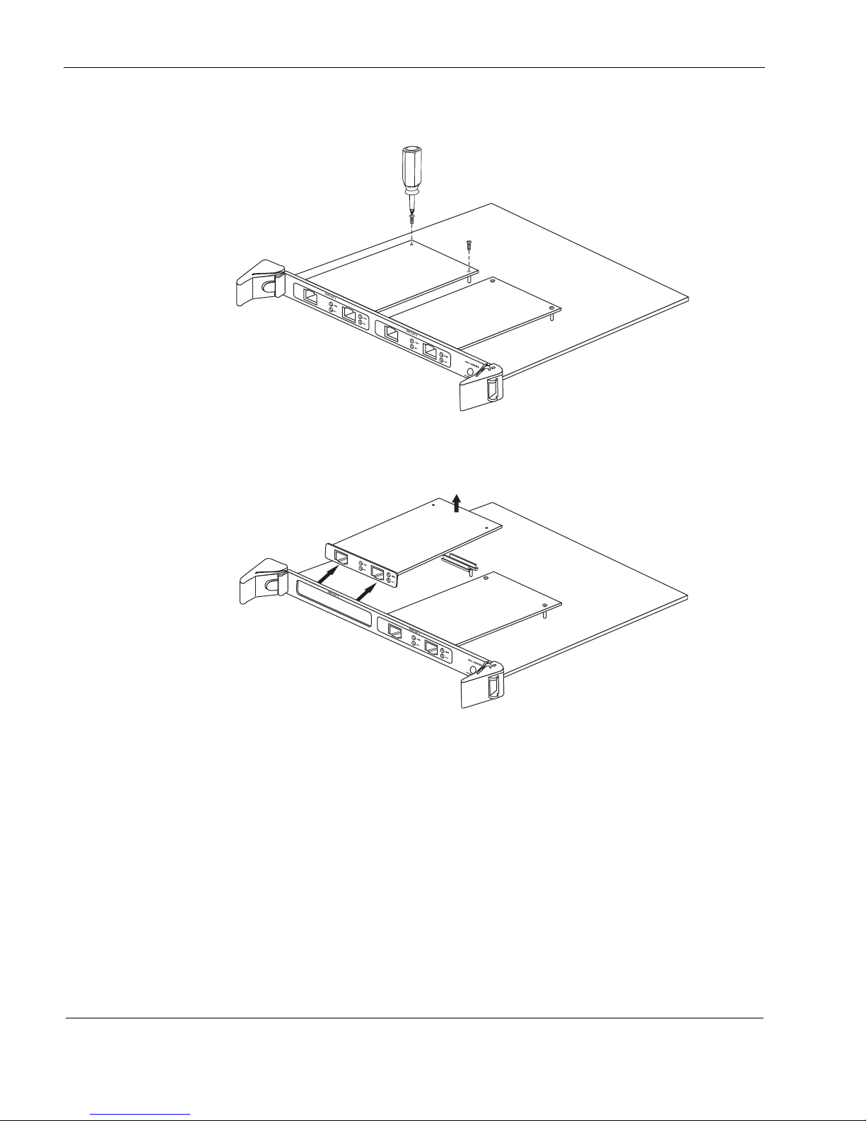
4 Installing and Replacing Network Interface Cards and ADP Services Modules
00312
10. Locate and remove the two NIC retaining screws from the back of the NIC.
11. Remove the NIC by lifting the back of the NIC away from the chassis tray assembly and
pulling it gently away from the front panel.
52 Check Point IP1280 Security Platform Installation Guide
00313a
Page 53
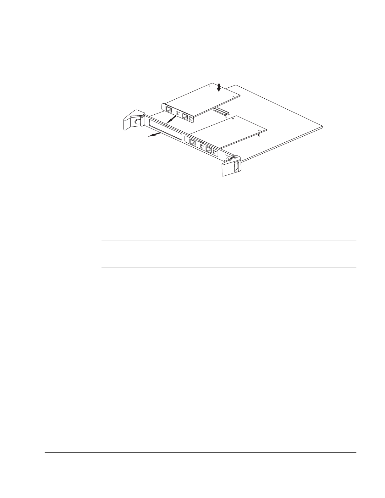
Removing, Installing, and Replacing NICs and ADP Modules
Note
12. Insert the new NIC or a blank bezel by doing one of the following:
a. Being careful to push down only where the motherboard connectors are located, press the
back end of the NIC down into the connectors until it is fully seated.
00314.1
b. If you are not replacing a NIC you are removing, insert a blank bezel into the location
formerly occupied by the NIC.
Make sure that the bezel is completely seated onto the slot on the front of the PMC
carrier and that the screw holes on the bottom of the bezel align with those on the bottom
of the PMC carrier. Proceed to step 14.
To reduce electromagnetic interference (EMI), a blank bezel needs to be installed in the
place of any NIC you have removed.
Check Point IP1280 Security Platform Installation Guide 53
Page 54
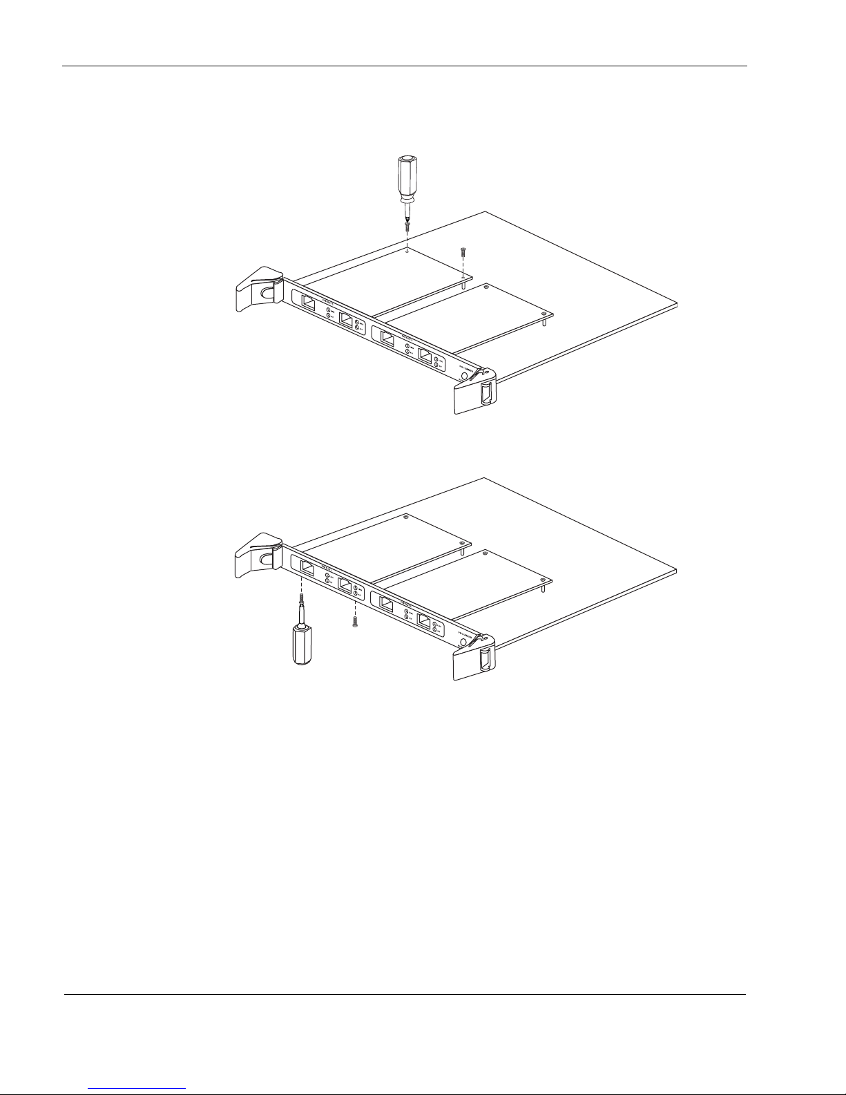
4 Installing and Replacing Network Interface Cards and ADP Services Modules
00312
00311
13. From the top of the PMC carrier, screw the NIC retaining screws into the standoffs on the
back of the NIC.
14. From the underside of the PMC carrier, screw in the bezel retaining screws.
15. Insert the PMC carrier or ADP module back into its original slot on the front of the IP1280
appliance until it clicks into place.
16. Press both levers to make sure that they are locked into place and power is restored to the
PMC carrier or ADP module.
54 Check Point IP1280 Security Platform Installation Guide
Page 55
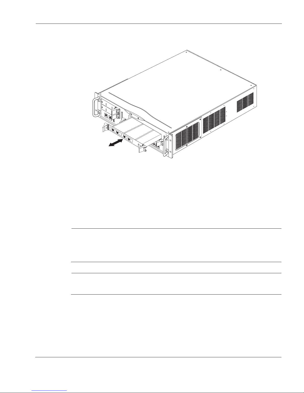
Removing, Installing, and Replacing NICs and ADP Modules
Note
Note
00643a
I
P
1
2
8
0
R
E
SET
C
O
N
S
O
L
E
A
U
X
A
U
X
2
H
D
D
B
S
L
O
T
3
S
L
O
T
2
S
L
O
T
1
H
D
D
A
HOT SWAP
H
O
T
S
W
A
P
P
O
W
E
R
A
C
T
I
V
I
T
Y
H
A
R
D
D
R
I
V
E
S
T
A
T
U
S
A
C
T
S
T
A
T
S
L
O
T
4
H
O
T
S
W
A
P
P
O
W
E
R
A
C
T
I
V
I
T
Y
H
A
R
D
D
R
I
V
E
S
T
A
T
U
S
1000BaseT
1
2
3
4
1000B-LX
A
C
T
L
I
N
K
1000B-LX
A
C
T
L
I
N
K
V2
S
U
B
S
L
O
T
1
S
U
B
S
L
O
T
2
P
O
W
E
R
R
E
A
D
Y
R
E
Q
U
E
S
T
H
O
T
S
W
A
P
F
I
O
C
A
R
R
I
E
R
V2
1000BaseT
A
C
T
L
I
N
K
A
C
T
L
IN
K
V2
1000BaseT
A
C
T
L
I
N
K
A
C
T
L
I
N
K
The power indicator LED on the PMC carrier or ADP module illuminates green.
.
If you are replacing a NIC or ADP module with a new NIC or ADP module of the same type, the
Check Point IPSO operating system automatically recognizes the NIC or ADP module and
applies the original configuration to the new NIC or ADP module.
If you are installing a new or different NIC or ADP module, configure the new NIC or ADP
module by using Check Point Network Voyager. For information about how to access Check
Point Network Voyager, see “Using Check Point Network Voyager” on page 42.
To replace a network interface card (NIC) in slot 3 or 4
Because power to an IP1280 is automatically disconnected when the chassis assembly is
opened, you do not need to manually disconnect the power for this procedure. Any servicing
of the appliance, however, should be completed with the chassis assembly fully removed
from the appliance.
Some figures for this procedure show a slot 3 NIC replacement, but the same procedure
applies for both slots 3 and 4.
1. Use Check Point Network Voyager or the CLI to perform an orderly shutdown of the
IP1280.
For information about how to access Check Point Network Voyager and the related
Check Point IP1280 Security Platform Installation Guide 55
reference materials, see “Using Check Point Network Voyager” on page 42.
Page 56
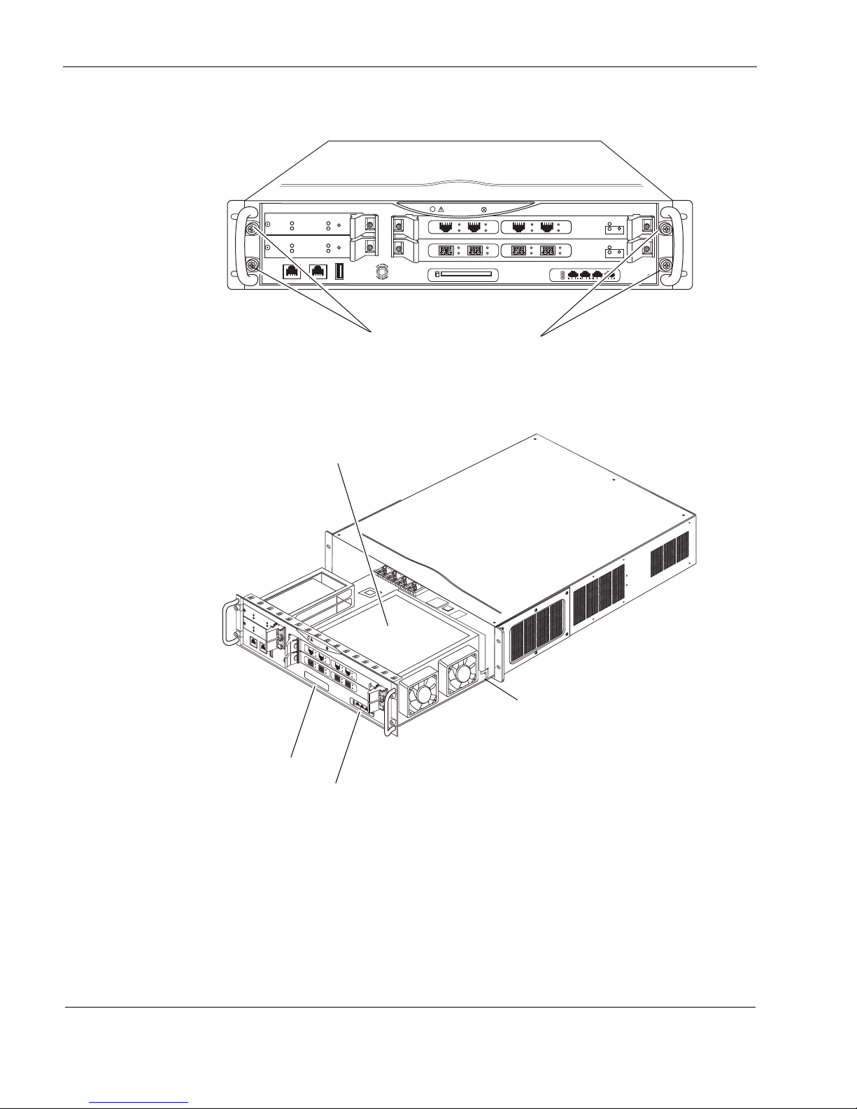
4 Installing and Replacing Network Interface Cards and ADP Services Modules
IP1280
RESET
00616a.1
CONSOLE AUX AUX2
HDD B
SLOT 3
SLOT 2
SLOT 1
HDD A
HOT SWAP
HOT SWAP
POWER
ACTIVITY
HARD DRIVE
STATUS
HOT SWAP
HOT SWAP
POWER
ACTIVITY
HARD DRIVE
STATUS
SLOT 4
1000BaseT
PC CARD
1
2
3
4
SUB SLOT 1 SUB SLOT 2
POWER
READY REQUEST
HOT SWAP
FIO CARRIER
1000B-LX
ACT
LINK
SUB SLOT 1 SUB SLOT 2
POWER
READY REQUEST
HOT SWAP
FIO CARRIER
1000B-LX
ACT
LINK
V2
1000BaseT
ACT
LINK
ACT
LINK
V2
1000BaseT
ACT
LINK
ACT
LINK
Chassis tray assembly screws
IP1280
R
ES
E
T
C
O
N
S
O
L
E
A
U
X
A
U
X
2
H
D
D
B
S
L
O
T
3
S
L
O
T
2
S
L
O
T
1
H
D
D
A
HOT SWAP
H
O
T
S
W
A
P
P
O
W
E
R
A
C
T
I
V
I
T
Y
H
A
R
D
D
R
I
V
E
S
T
A
T
U
S
HOT SWAP
H
O
T
S
W
A
P
P
O
W
E
R
A
C
T
I
V
I
T
Y
H
A
R
D
D
R
I
V
E
S
T
A
T
U
S
S
L
O
T
4
00637a
1000BaseT
1
2
3
4
SUB SLOT 1
SUB SLOT 2
POWER
READY
REQUEST
HOT SWAP
FIO CARRIER
1000B-LX
A
C
T
LI
N
K
SUB SLOT 1
SUB SLOT 2
POWER
READY
REQUEST
HOT SWAP
FIO CARRIER
1000B-LX
ACT
LI
N
K
V2
1000BaseT
A
C
T
L
I
N
K
A
C
T
L
I
N
K
V2
1000BaseT
A
C
T
L
I
N
K
A
C
T
L
I
N
K
PMC carrier shield
Slot 3
Tray release lever
Slot 4
2. Loosen the four front panel retaining screws.
3. Slide the chassis tray assembly forward, press and tray release lever, and completely remove
the tray from the appliance.
4. Remove the six screw that secure the metal shield above the two PMC carriers and remove
the shield.
56 Check Point IP1280 Security Platform Installation Guide
Page 57
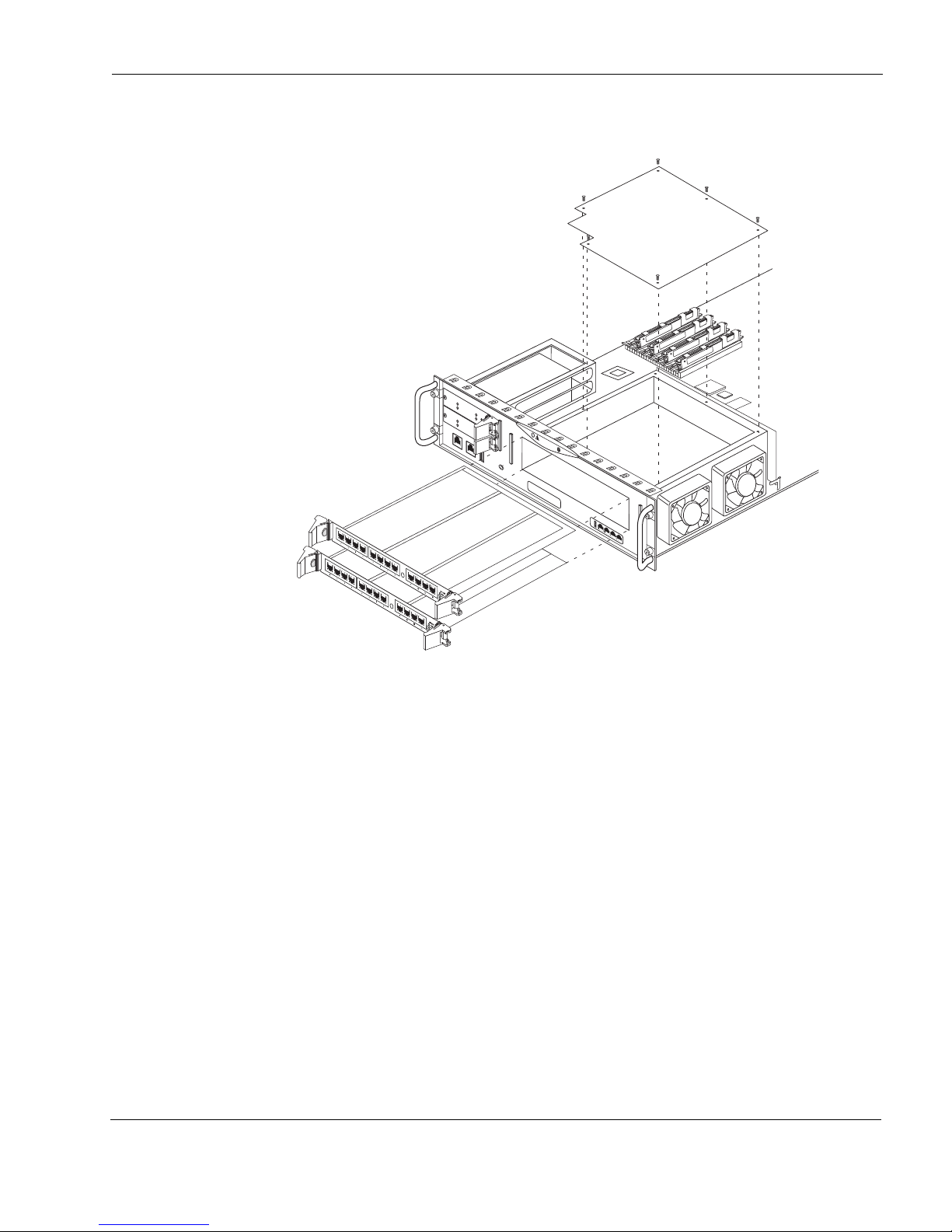
Removing, Installing, and Replacing NICs and ADP Modules
I
P
1
2
8
0
RE
SET
C
O
N
S
O
L
E
A
U
X
A
U
X
2
H
D
D
B
S
L
O
T
3
S
L
O
T
2
H
D
D
A
H
O
T
S
W
A
P
H
O
T
S
W
A
P
P
O
W
E
R
A
C
T
I
V
I
T
Y
H
A
R
D
D
R
I
V
E
S
T
A
T
U
S
H
O
T
S
W
A
P
H
O
T
S
W
A
P
P
O
W
E
R
A
C
T
I
V
I
T
Y
H
A
R
D
D
R
I
V
E
S
T
A
T
U
S
S
L
O
T
4
00654a.1
1000BaseT
1
2
3
4
Remove PMC carriers
Remove six
screws and
PMC carrier
shield
5. Remove any installed PMC carriers so that both slot 1 and slot 2 are not occupied.
6. Remove the two front bezel screws and remove the slot 3 or slot 4 filler panel or installed
NIC.
Check Point IP1280 Security Platform Installation Guide 57
Page 58
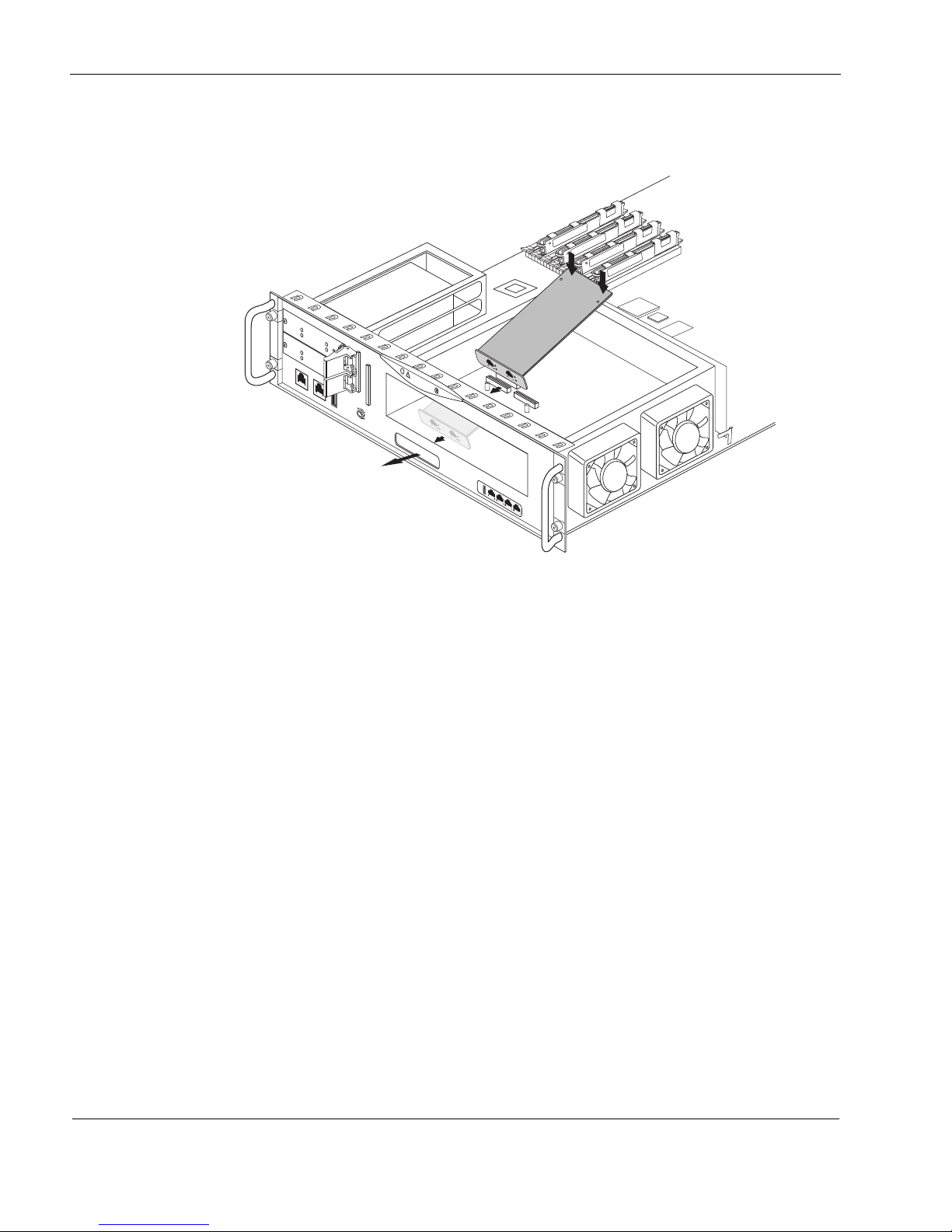
4 Installing and Replacing Network Interface Cards and ADP Services Modules
00657a.2
IP1280
R
E
S
E
T
C
O
N
S
O
L
E
A
U
X
A
U
X
2
H
D
D
B
S
L
O
T
3
SLOT 2
S
L
O
T
1
H
D
D
A
H
O
T
S
W
A
P
HOT SWAP
P
OW
ER
ACTIVI
T
Y
HA
RD DRIVE
STA
TUS
H
O
T
S
W
A
P
HOT
S
WA
P
POW
ER
ACTIVITY
HARD DRIVE
S
TAT
US
S
L
O
T
4
1000BaseT
1
2
3
4
L
INK
A
CT
V
2
L
INK
A
C
T
1
0
0
0
B
a
s
e
T
LIN
K
A
CT
V
2
LI
NK
ACT
1
0
0
0
B
a
s
e
T
7. Raise the back end of the NIC approximately 45 degrees as you insert the front end into slot
3 in the front panel.
58 Check Point IP1280 Security Platform Installation Guide
Page 59
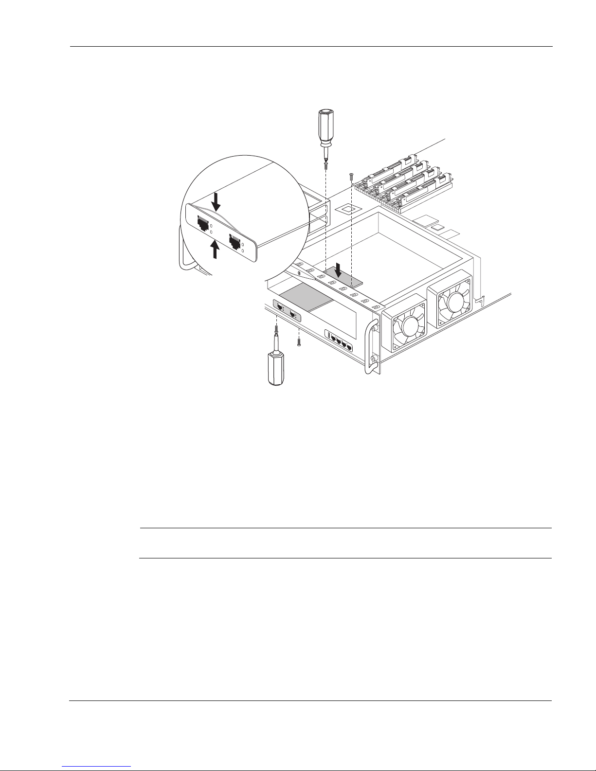
Removing, Installing, and Replacing NICs and ADP Modules
Note
Take care that the
EMI gasket doesn’t
roll back during NIC
installation
Arrows indicate
locations where the
gasket might roll back
Secure the two rear
NIC screws
Reinstall the two bezel screws
8. Being careful to push down only where the motherboard connectors are located, press the
back end of the NIC down into the connectors until it is fully seated.
1000BaseT
H
AR
D
DR
LINK
IVE
S
HDD A
T
PC CARD
A
TU
ACT
S
A
C
TIV
T
I
Y
HA
RD
D
RIVE
PO
WE
R
H
O
T
W
S
LI
AP
S
T
A
TU
S
A
C
TIV
T
I
Y
C
ONSOLE
NK
H
O
T
W
S
A
P
A
CT
PO
WER
H
O
T SW
AP
HO
T
W
S
A
P
HDD B
A
UX
A
UX2
1000BaseT
S
LO
T 1
S
L
OT 3
LINK
A
C
T
LINK
S
LO
T 2
A
CT
1
2
3
1000BaseT
4
IP1280
S
LOT 4
Check Point IP1280 Security Platform Installation Guide 59
R
E
S
E
T
00644a.2
9. Secure the back end of the NIC with the two screws provided with the kit.
10. Secure the front end of the NIC by replacing the two front bezel screws that you removed
previously.
11. Slide the chassis assembly back into the appliance until it clicks into place.
12. Resecure the chassis assembly retaining screws.
13. Press the power switch, located on each power supply at the back of the appliance, to turn on
the power to the appliance.
Make sure that you turn on both power supplies.
If you are replacing a NIC with a new NIC of the same type, the Check Point IPSO operating
system automatically recognizes the NIC and applies the original configuration to the new NIC.
If you are installing a new or different NIC, configure the new NIC by using Check Point
Network Voyager. For information about how to access Check Point Network Voyager, see
“Using Check Point Network Voyager” on page 42.
Page 60

4 Installing and Replacing Network Interface Cards and ADP Services Modules
Configuring and Activating Interfaces
The Check Point IP1280 appliance automatically detects any new interfaces when either PMC
carrier or ADP module is correctly installed. Use Check Point Network Voyager to configure
and activate the logical and physical interfaces on the NIC or ADP module.
For information about configuring and activating ADP module interfaces, see Chapter 6, “About
IP1280 Appliance ADP Services Modules.”
For information about how to access Check Point Network Voyager and the related reference
materials, see “Using Check Point Network Voyager” on page 42.
Monitoring Network Interface Cards or ADP Modules
You can assess the general operating condition of the NICs or ADP modules in your appliance
by looking at the LED status indicators on each NIC or ADP module.
The status indicators for each NIC are explained in Chapter 5, “About IP1280 Appliance
Network Interface Cards.”
The status indicators for ADP modules are explained in Chapter 6, “About IP1280 Appliance
ADP Services Modules.”
Use Check Point Network Voyager to access detailed port information. For information about
how to access Check Point Network Voyager, see “Using Check Point Network Voyager” on
page 42.
You can also use the Check Point IPSO tcpdump command to examine the traffic on a specific
port.
60 Check Point IP1280 Security Platform Installation Guide
Page 61

5 About IP1280 Appliance Network
Caution
Interface Cards
This chapter describes the network interface cards available for the Check Point IP1280
appliance and how to connect those NICs to your network. The following NICs are described:
Four-Port 10/100 Ethernet NICs
Two-Port Fiber-Optic Gigabit Ethernet NICs
Two-Port and Four-Port Copper Gigabit Ethernet NIC
For instructions about how to add or replace NICs, see Chapter 4, “Installing and Replacing
Network Interface Cards and ADP Services Modules.”
The NICs supported in the IP1280 operate at the peripheral component interconnect (PCI)
frequency listed in Tab le 8.
Table 8 NIC PCI Frequency
NIC or interface port Maximum PCI operation supported
10/100 Ethernet 133 MHz
Fiber-optic Gigabit Ethernet 133 MHz
Copper Gigabit Ethernet (10/100/1000) 133 MHz
To protect the IP1280 and the memory modules from electrostatic discharge damage,
make sure you are properly grounded before you touch these components. Use a
grounding wrist strap and follow the instructions provided with the wrist strap before
you handle the components or open the appliance. The grounding plug on the front of
the appliance (shown in Figure 1 on page 17) provides a chassis grounding point. If
you do not have a grounding wrist strap, make sure you are properly grounded before
you touch any electronic component.
IP1280 Security Platform Installation Guide 61
Page 62
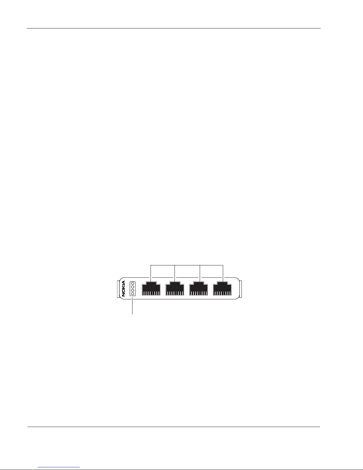
5 About IP1280 Appliance Network Interface Cards
00026.2
321
1
2
3
4
4
10/100 BaseT
Activity LED (blinking green)
Link LED (solid green)
Ports
RJ-45 connectors
Four-Port 10/100 Ethernet NICs
The IP1280 supports Check Point-approved, four-port UTP5 dual-mode (10-Mbps and 100Mbps) Ethernet NICs installed in a 6U PMC carrier or in slot 3 (slot 4 is reserved for a four-port
copper Gigabit Ethernet NIC). When you purchase a 10/100 Ethernet NIC with your IP1280, the
NIC is installed before the appliance is delivered to you. For information about how to add or
replace a NIC, see Chapter 4, “Installing and Replacing Network Interface Cards and ADP
Services Modules.”
10/100 Ethernet NIC Features
The four-port 10/100 Ethernet NIC supports PCI operation at 133 MHz and runs on Check Point
IPSO 4.2 or higher.
Both the four-port and two-port Ethernet NICs support the following features:
Hot swappability
Tracing through tcpdump
PCI operation at 33 MHz and 66 MHz
Compliance with IEEE 802.3z Gigabit Ethernet specification
You can configure and monitor Ethernet NIC interfaces by using Check Point Network Voyager.
Specifically, you set the port speed and full-duplex or half-duplex mode with Check Point
Network Voyager.
For information about how to access Check Point Network Voyager and the related reference
materials, see “Using Check Point Network Voyager” on page 42.
Figure 11 Four-Port 10/100 Ethernet NIC Front Panel Details
After the power is turned on and the cables are connected, the Ethernet link LEDs on both the
IP1280 and on the remote equipment illuminate to indicate the connection. As data is
transmitted, the activity LEDs on the appliance illuminate.
62 IP1280 Security Platform Installation Guide
Page 63
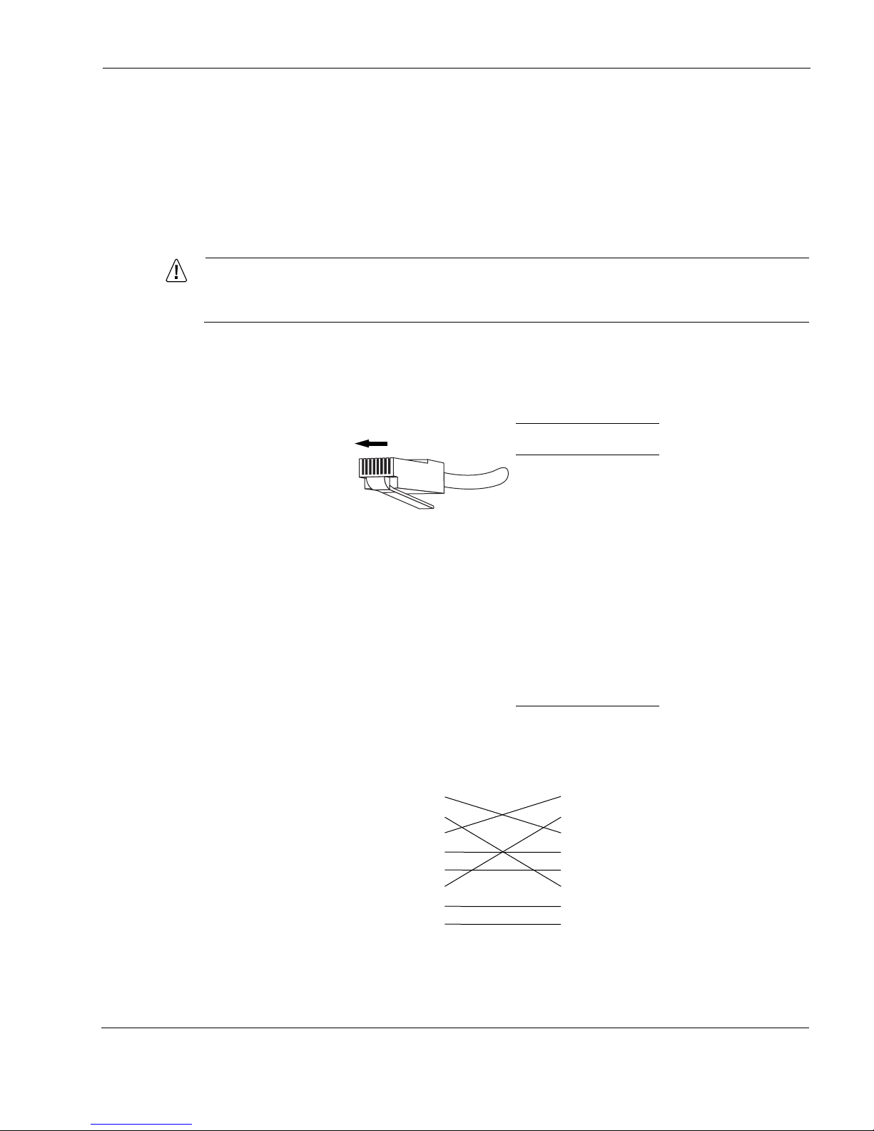
Ethernet NIC Connectors and Cables
Caution
00270
Pin Assignment
1TX +
2TX -
3RX +
4
5
6RX -
7
8
81
00017.1
1
2
3
4
5
6
7
8
1
2
3
4
5
6
7
8
The Ethernet connectors on the two-port and four-port 10/100 Ethernet NICs are RJ-45
connectors. Use a straight-through cable to connect the NIC to a hub or switch, or a crossover
cable to connect directly to a host.
Use IEEE 802.3 10/100 BASE-TX Cat 5 unshielded twisted-pair, full-duplex, or half-duplex
cable. You can order appropriate adapter cables separately from a cable vendor of your choice.
Cables that connect to the Ethernet card must be IEEE 802.3 compliant to prevent
potential data loss.
Figure 12 shows the pin assignments for the RJ-45 cable. The connector is numbered from right
to left, with the copper tabs facing up and toward you.
Figure 12 Output Connector for the Ethernet Cable
Four-Port 10/100 Ethernet NICs
Figure 13 shows the pin assignments for the RJ-45 cross-over cable.
Figure 13 Ethernet Crossover-Cable Pin Connections
IP1280 Security Platform Installation Guide 63
Page 64
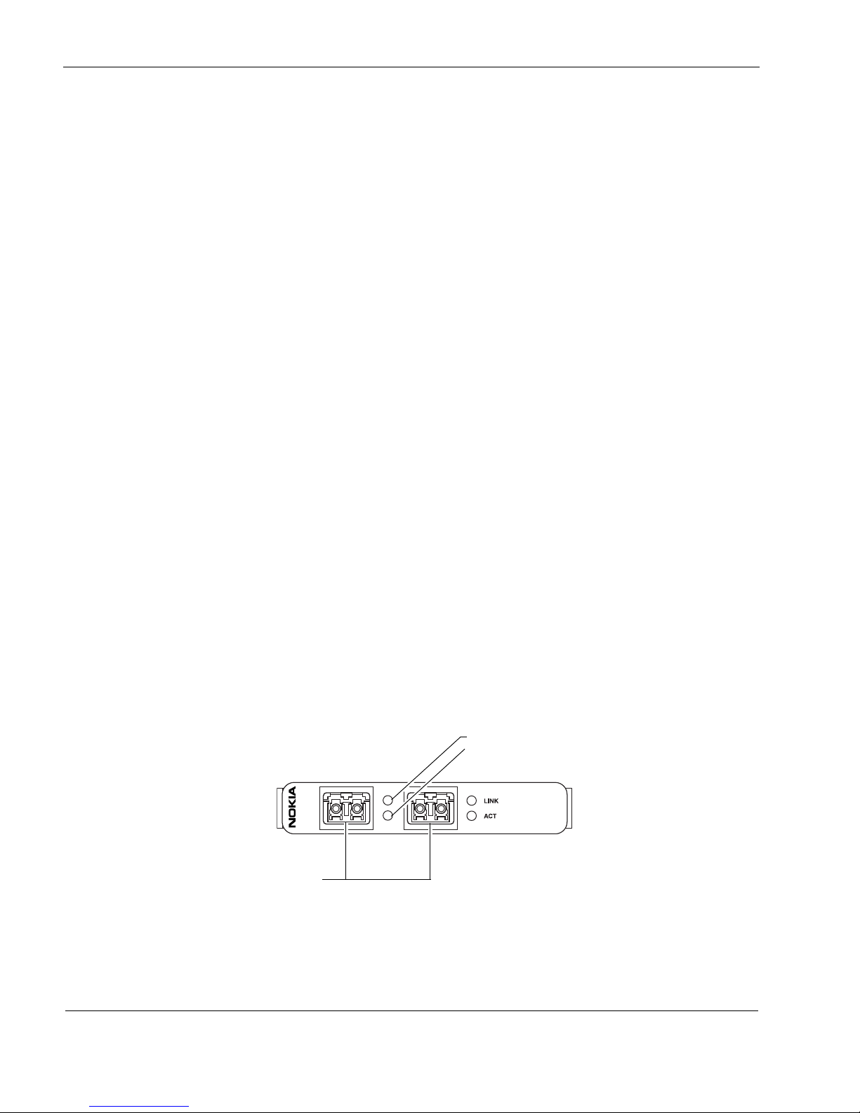
5 About IP1280 Appliance Network Interface Cards
00206
GIGE
Link LEDs (solid green)
Activity LEDs (blinking amber)
Ports
Two-Port Fiber-Optic Gigabit Ethernet NICs
The IP1280 supports Check Point-approved, two-port, fiber-optic Gigabit Ethernet NICs
installed on a PMC expansion slot. The IP1280 can accommodate up to four Gigabit Ethernet
NICs.
When you purchase a Gigabit Ethernet NIC with your IP1280, the NIC is installed before the
appliance is delivered to you. For information about how to add or replace a NIC, see Chapter 4,
“Installing and Replacing Network Interface Cards and ADP Services Modules.”
Fiber-Optic Gigabit Ethernet NIC Features
The short-range and long-range fiber-optic Gigabit Ethernet NICs support:
High bandwidth
Full-duplex mode operation up to 1 Gbps (no half-duplex support)
Link speed auto advertising
Tracing through tcpdump
Compliance with IEEE 802.3z Gigabit Ethernet specification
The short-range multi-mode fiber (MMF) fiber-optic Gigabit Ethernet NICs in the IP1280 run
on Check Point IPSO 4.2 or higher.
The long-range single-mode fiber (SMF) fiber-optic Gigabit Ethernet NICs in the IP1280 run on
Check Point IPSO 4.2 or higher.
You can configure and monitor Gigabit Ethernet NIC interfaces with Check Point Network
Voyager. Specifically, you set the port speed and full-duplex mode with Check Point Network
Voyager.
For information about how to access Check Point Network Voyager and the related reference
materials, see “Using Check Point Network Voyager” on page 42.
Figure 14 shows the front panel details for the two-port short-range (1000 BASE-SX) fiber-optic
Gigabit Ethernet NIC you can use in IP1280 appliance.
Figure 14 PMC Two-Port Short-Range Gigabit Ethernet NIC
64 IP1280 Security Platform Installation Guide
Page 65
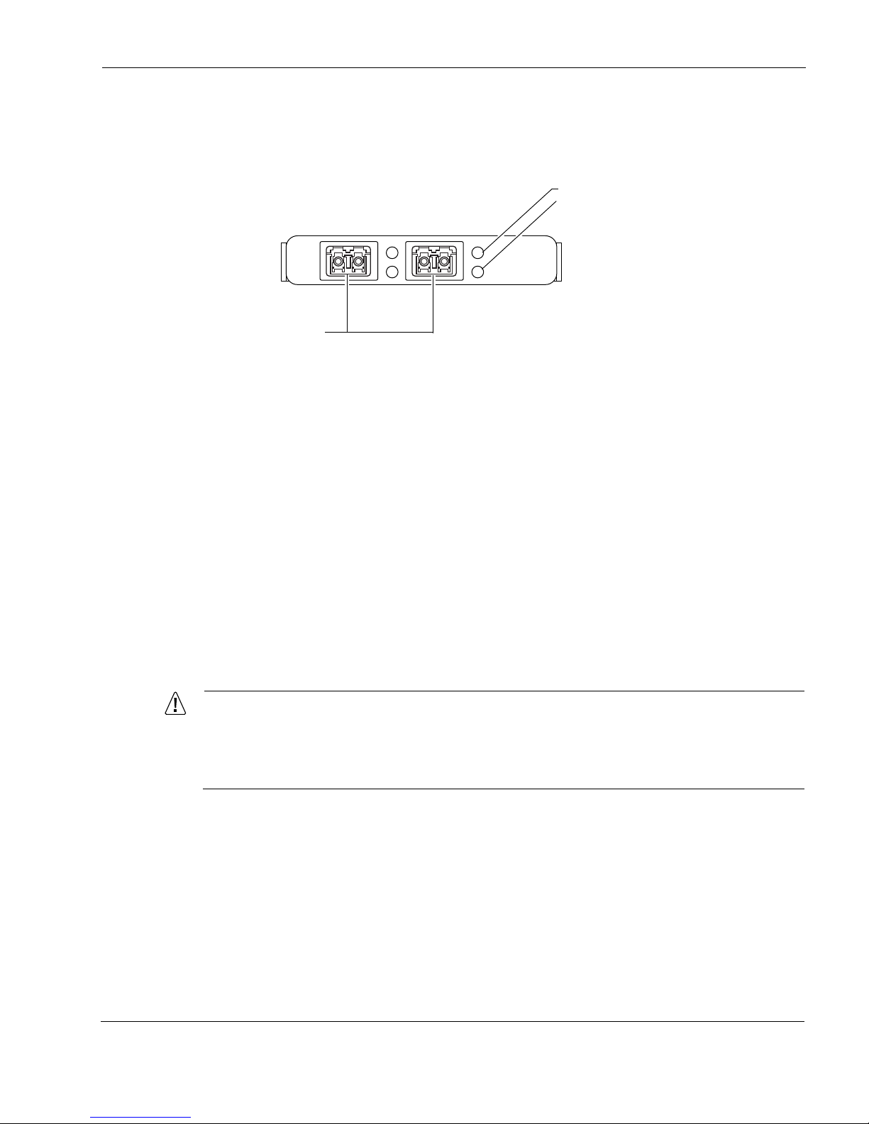
Two-Port Fiber-Optic Gigabit Ethernet NICs
Caution
00555
LINK
ACT
1000B-LX
Link LEDs (solid green)
Activity LEDs (blinking amber)
Ports
Figure 15 shows the front panel details for the two-port long-range (1000 BASE-LX) fiber-optic
Gigabit Ethernet NIC you can use in your IP1280.
Figure 15 PMC Two-Port Long-Range Gigabit Ethernet NIC
After the power is turned on and the cables are connected, the Ethernet link LEDs on both the
IP1280 and on the remote equipment illuminate to indicate the connection. As data is
transmitted, the activity LEDs on the appliance illuminate.
Fiber-Optic Gigabit Ethernet NIC Connectors and Cables
For short-range NICs, to connect the fiber-optic Gigabit Ethernet NIC to other network
components, use a multi-mode, fiber-optic cable with an LC connector for each NIC interface.
You can use either 50 or 62.5 micron cable; 50 micron-type cable provides longer transmission
reach.
For long-range NICs, to connect the fiber-optic Gigabit Ethernet NIC to other network
components, use a single-mode, fiber-optic cable with an LC connector for each NIC interface.
The destination end of the cable can be either LC or SC, depending on the type of connector
required for the destination Gigabit Ethernet device. You can also use a half-duplex LC-to-LC
cable to loop back the transmit port of an interface to the receiver port. LC and SC define the
fiber-optic connector types; LC connectors are smaller than SC connectors.
Depending on the product you order, one or more LC-to-SC cables are included with
fiber-optic Gigabit Ethernet NICs. You can order additional cables from a cable vendor
of your choice.Cables that connect to the Gigabit Ethernet NIC must be IEEE 802.3z
compliant to prevent potential data loss.
Performance Considerations
If you are using two two-port fiber-optic Gigabit Ethernet NICs in an IP1280, place one NIC in
each of the two 6U PMC carrier units to get maximum system throughput. Each 6U PMC carrier
unit has a separate PCI bus connection to the main system motherboard. In the configuration
described here, each of the two fiber-optic two-port Gigabit Ethernet NICs access a separate PCI
bus.
IP1280 Security Platform Installation Guide 65
Page 66
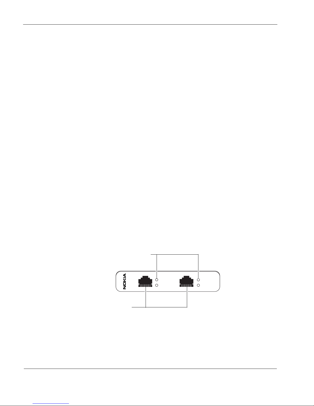
5 About IP1280 Appliance Network Interface Cards
00386.5
LINK
ACT
V2
LINK
ACT
1000BaseT
Link LEDs (green or yellow)
Activity LEDs (yellow)
Ports
Two-Port and Four-Port Copper Gigabit Ethernet NIC
The Check Point IP1280 appliance supports Check Point-approved, two-port and four-port
copper Gigabit Ethernet NICs installed on a 6U PMC carrier or in slot 3 (slot 4 is reserved for a
four-port copper Gigabit Ethernet NIC and it is replaceable). The IP1280 can accommodate up
to six Gigabit Ethernet NICs.
When you purchase a copper Gigabit Ethernet NIC with your IP1280, the NIC is installed before
the appliance is delivered to you. For information about how to add or replace a NIC, see
Chapter 4, “Installing and Replacing Network Interface Cards and ADP Services Modules.”
Copper Gigabit Ethernet NIC Features
The copper Gigabit Ethernet NIC supports:
High bandwidth
Full-duplex mode operation up to 1 Gbps
Link speed auto advertising (10/100/1000)
Hot swapping
PCI operation at 33 MHz, 66 MHz, and 133 Mhz
Compliance with IEEE 802.3z and 802.3ab Gigabit Ethernet specifications
You can configure and monitor Gigabit Ethernet NIC interfaces with Check Point Network
Voyager. Specifically, you can use Check Point Network Voyager to set the port speed and
full-duplex mode to 1000, 100, or 10 Mbps.
For information about how to access Check Point Network Voyager and the related reference
materials, see “Using Check Point Network Voyager” on page 42.
Figure 16 shows the front panel details for the PMC two-port copper Gigabit Ethernet NIC you
can use in Check Point IP1280 appliances.
Figure 16 Two-Port Copper Gigabit Ethernet NIC Front Panel Details
Figure 17 shows the front panel details for the PMC four-port copper Gigabit Ethernet NIC you
can use in Check Point IP1280 appliances.
66 IP1280 Security Platform Installation Guide
Page 67
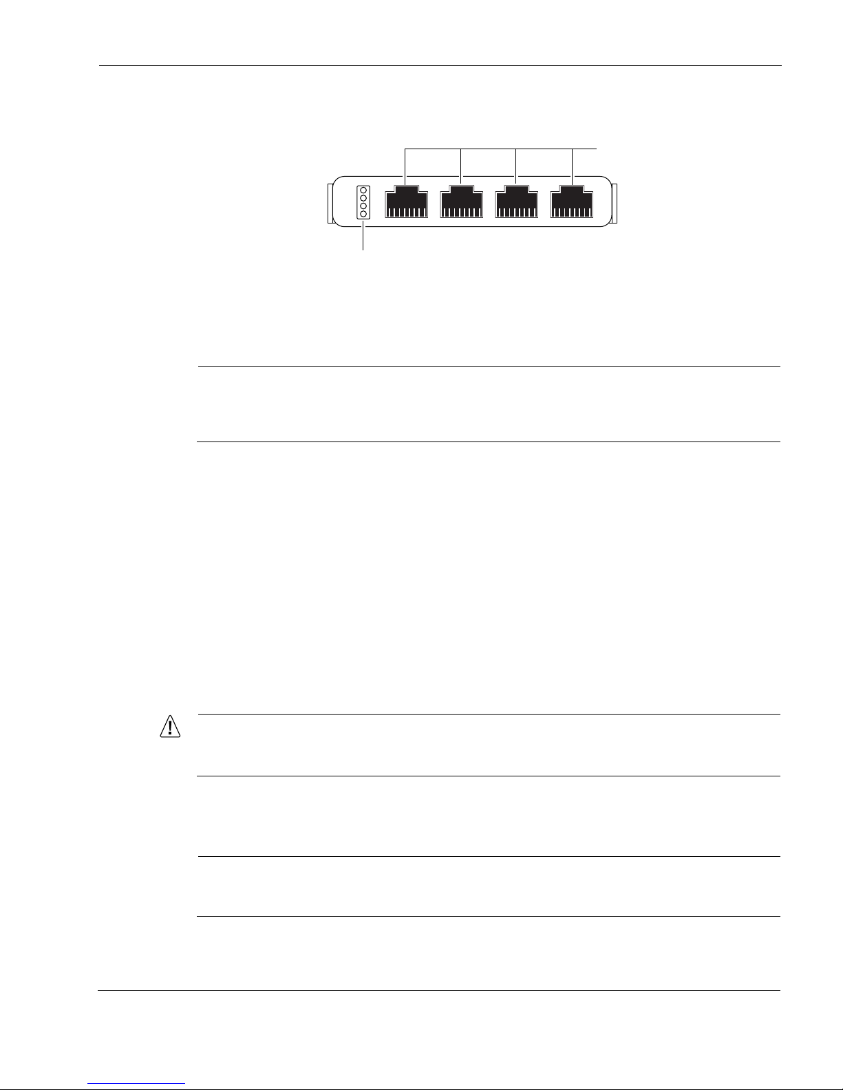
Two-Port and Four-Port Copper Gigabit Ethernet NIC
Note
Caution
Note
00641
321
1
2
3
4
4
1000 BaseT
Link LEDs (solid green)
Activity LEDs (blinking green)
Ports
Figure 17 Four-Port Copper Gigabit Ethernet NIC Front Panel Details
After the power is turned on and the cables are connected, the Ethernet link LEDs on both the
IP1280 and on the remote equipment illuminate to indicate the connection.
The Link LED on the NIC is bicolored. A green LED indicates a 1 Gbps link speed, and a
yellow LED indicates a 10/100 Mbps link speed. As the NIC transmits data, the activity LEDs
on the appliance illuminate.
Performance Considerations
If you are using two two-port or four-port copper Gigabit Ethernet NICs in an IP1280, place one
NIC in each of the two 6U PMC carrier units to get maximum system throughput. Each 6U PMC
carrier unit has a separate PCI bus connection to the main system motherboard. In the
configuration described here, each of the two copper Gigabit Ethernet NICs access a separate
PCI bus.
Two-Port Copper Gigabit Ethernet NIC Connectors and Cables
The IP1280 receptacles are RJ45 connectors.
Cables that connect to the Gigabit Ethernet card must be IEEE 802.3 compliant to
prevent potential data loss.
To connect to a hub, switch, or router, use a straight-through RJ-45 cable (Cat 5 type cable, or as
required by your network configuration).
Certain circumstances might require shielded Cat 5 Ethernet cables to meet Class B
emissions requirements.
IP1280 Security Platform Installation Guide 67
Page 68
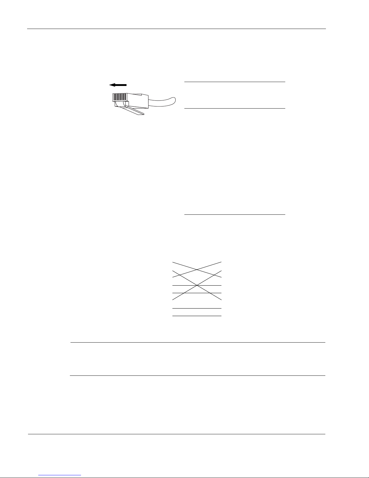
5 About IP1280 Appliance Network Interface Cards
Note
00270
81
Pin#
Gigabit
Ethernet
Assignment
10/100 Mbps
Assignment
1BI_DA+ TX
2BI_DA- TX
3BI_DB+ RX
4
BI_DC+
5
BI_DC-
6BI_DB- RX
7BI_DD+
8BI_DD-
00017.1
1
2
3
4
5
6
7
8
1
2
3
4
5
6
7
8
In Figure 18, the RJ-45 cable output connector is numbered from right to left, with the copper
pins facing up and toward you.
Figure 18 Ethernet Cable Connector Output Pin Assignments
To connect directly to a host, use an RJ-45 crossover cable wired as Figure 19 shows.
Figure 19 Ethernet Crossover Cable Pin Connections
After you turn on the appliance, the Ethernet link LEDs on both the appliance and on the
remote equipment illuminate to indicate the connection. As data is transmitted or received,
the activity LEDs on the appliance illuminate.
To connect the IP1280 to other network components, you can order appropriate adapter cables
separately from a cable vendor of your choice.
68 IP1280 Security Platform Installation Guide
Page 69

6 About IP1280 Appliance ADP Services
Note
Modules
This chapter describes the Accelerated Data Path (ADP) services modules available for the
Check Point IP1280 appliance and how to connect those modules to your network. It includes
the following sections:
Installing and Replacing ADP Modules
Using ADP Transceivers in ADP Modules
Identifying ADP Module and Transceiver Types with Latch Lever Color Codes
Check Point ADP Module LED Reference Information
Configuring Check Point IPSO for IP1280 ADP Interfaces
Check Point IP1280 ADP modules help to accelerate firewall and VPN throughput on
connections that benefit from the Check Point SecureXL feature. ADP is a technology designed
to forward packets at the highest possible rate. Check Point ADP modules provide this
technology by offloading processing from the CPU to network processors.
For IP1280 appliances, ADP is implemented with a single module.
You can use only one ADP module at a time, and you can install the module in either slot 1
or 2.
One version of the module has built-in RJ-45 ports that provide 10/100/1000 Gigabit Ethernet
service. Other versions use swappable ADP transceivers to provide several different types of
services. Hardware configurations available from Check Point are described in the following
table.
ADP module type Number of ports Supported speeds Supported ADP transceivers
Build in RJ-45 12 10/100/1000 Mbps n.a.
IP1280 Security Platform Installation Guide 69
Page 70

6 About IP1280 Appliance ADP Services Modules
Note
Note
Note
ADP module type Number of ports Supported speeds Supported ADP transceivers
Gigabit Ethernet SFP 12 1000 Mbps
10 Gigabit Ethernet XFP 3 10 Gbps
• Fiber-optic (short range)
• Fiber-optic (long range)
• Copper
• Fiber-optic (short range)
• Fiber-optic (long range)
For information about how to identify short-range and long-range ADP transceivers, see “To
install or remove ADP transceivers in a Check Point ADP module” on page 74. The ADP
transceivers are hot swappable.
Check Point supports only ADP modules and ADP transceivers sold by Check Point. For
further information, contact your Check Point representative.
For IP1280 appliances, you need to install Check Point IPSO 6.x or later to use ADP
modules.
Installing and Replacing ADP Modules
Before you begin this procedure, you should review all ADP module information in the
Getting Started Guide and Release Notes for the version of Check Point IPSO you are
using.
Use these instructions to install an ADP module in your appliance.
Before You Begin
To install a Check Point ADP module, you need the following:
A Phillips-head screwdriver
Physical access to the appliance
Access to the appliance by using Check Point Network Voyager or the CLI
A suitable, grounded work surface
The ADP module kit
70 IP1280 Security Platform Installation Guide
Page 71

Installing and Replacing ADP Modules
Note
Caution
Note
To install an ADP module in IP1280 appliances
For information about how to install or replace Check Point ADP module in your appliance, see
Chapter 4, “Installing and Replacing Network Interface Cards and ADP Services Modules.”
There are few differences between the procedures for installing and replacing IP1280 PMC NIC
card carriers and ADP modules other than the following steps and considerations:
Before you remove your PMC NIC card carriers and replace them with your ADP module,
do the following:
You cannot preserve the configuration for slots 1 and 2 of your appliance when you
replace a PMC NIC card carrier with an ADP module or, conversely, when you replace
your ADP module with a PMC NIC card carrier due to interface naming convention
differences. Therefore, you need to delete all existing configurations associated with any
affected slots.
Upgrade the Check Point IPSO software to the required version as described in the
Getting Started Guide and Release Notes that you received with your ADP module.
Remove the installed PMC card carrier for a slot that you are installing ADP modules in. For
the card carrier removal procedure, see Chapter 4, “Installing and Replacing Network
Interface Cards and ADP Services Modules.”.
You must first power down your appliance before you remove any installed card carriers.
When you install an ADP module, take care not to scrape the bottom surface, as this
can damage the device.
After you slide the ADP module into the carrier slot, secure the two screws and ensure that
both of the ejector and locking levers are fully secured.
After you physically install the ADP module, reboot the system and reconfigure the
interfaces as described in “Configuring Check Point IPSO for IP1280 ADP Interfaces” on
page 76.
The following figure shows the fiber and copper IP1280 Gigabit Ethernet ADP modules and
card carrier assemblies.
Hot Swap switch functionality is not supported by Check Point IPSO at the time of this
guide’s publication. The RDY LED, however, illuminates during booting and then turns off.
IP1280 Security Platform Installation Guide 71
Page 72

6 About IP1280 Appliance ADP Services Modules
Note
You might notice that the orange Activity LED, as shown in the following figure, might blink at
longer intervals than typical for traffic when an ADP module port is connected to a switch.
This likely indicates that the switch is sending ARP (address restoration protocol) requests
to the port, and no traffic is present.
72 IP1280 Security Platform Installation Guide
Page 73
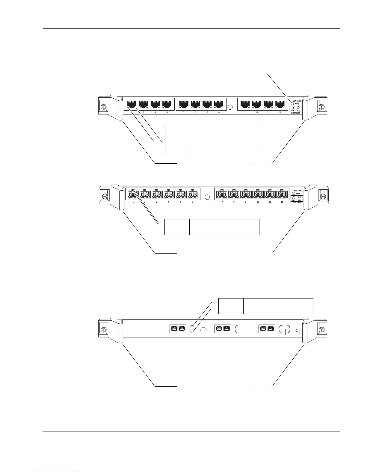
Figure 20 ADP Module Front Panel Details and LED Information
00656
Power LED illuminates green when
the ADP module is under power
Ejector and locking levers
Twelve-port copper Gigabit Ethernet ADP module
Twelve-port copper and fiber Gigabit Ethernet ADP module (fiber in this example)
Link 10/100 Mbps: Orange
(solid)
1000 Mbps: Green (solid)
Activity Orange (blinking)
Activity Orange (blinking)
Link 1000 Mbps: Green (solid)
Ejector and locking levers
Link 10 Gbps: Green (solid)
Activity Orange (blinking)
Ejector and locking levers
Three-port fiber10 Gigabit Ethernet ADP module
Installing and Replacing ADP Modules
00655
1
L
A
23
L
A
ADP 10G CARD
LAPWR
RDY
HOT SWAP
REQ
00658
IP1280 Security Platform Installation Guide 73
Page 74
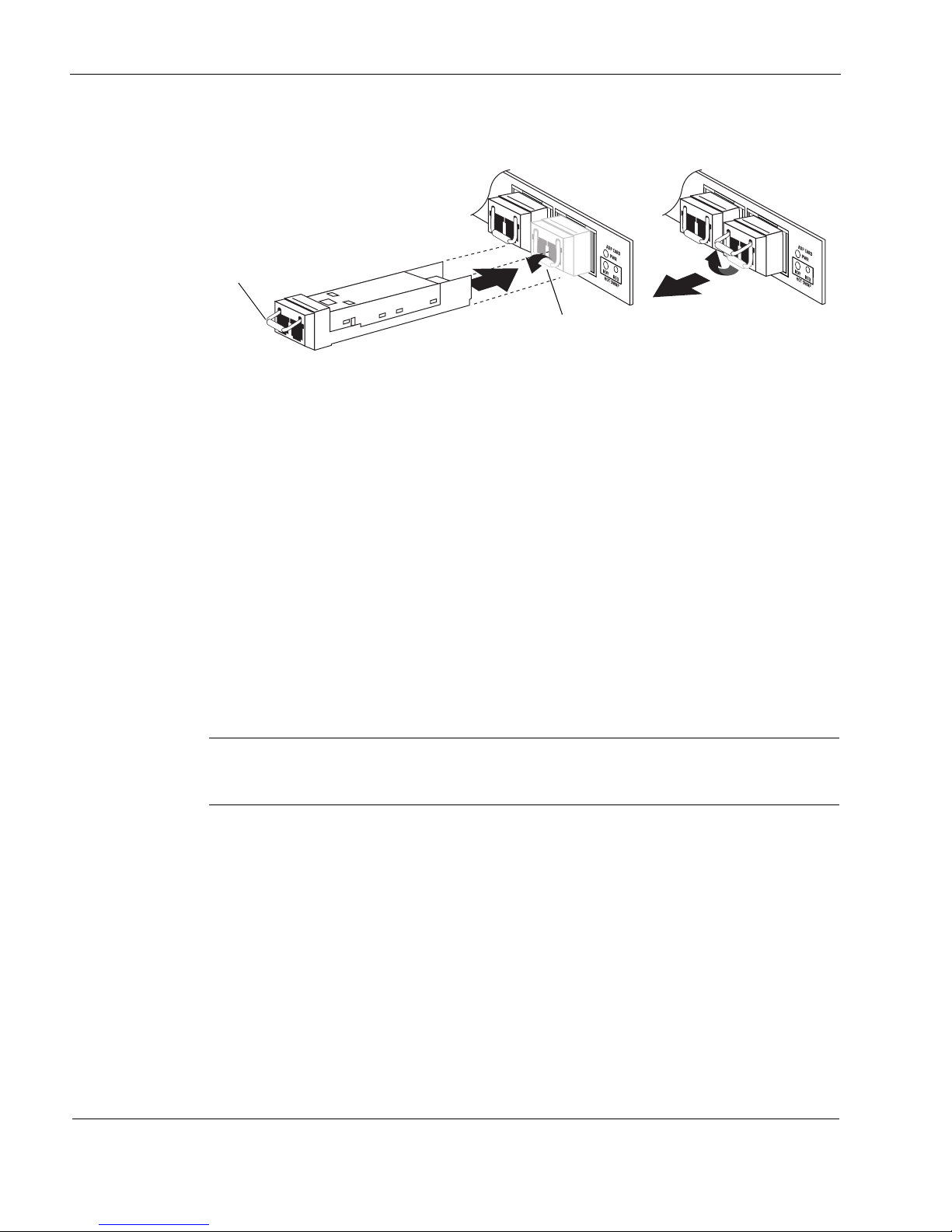
6 About IP1280 Appliance ADP Services Modules
Note
00652a
Latch lever
Flip latch lever down before inserting
the ADP transceiver
Using ADP Transceivers in ADP Modules
For ADP modules that require ADP transceivers, refer to the following procedure, which
describes how to install or remove Check Point ADP transceivers. The transceivers are hot
swappable as are the interface cables you use with them. Rotate the latch levers up or down to
secure transceivers, or to release them for removal. You do not need to change the interface type
in Check Point Network Voyager or the CLI, as the system makes the configuration changes
automatically.
Hardware configurations available from Check Point that use ADP are described in the table on
on page 69.
To identify the types of transceivers you are using in your ADP modules, refer to Table 9 on
page 75.
To install or remove ADP transceivers in a Check Point ADP module
To install an ADP transceiver:
Push the transceiver into an available port in the ADP module.
Rotate the transceiver latch lever down to secure the transceiver in the ADP module.
Depending on the design of your ADP transceiver, you might need to rotate the latch
lever upward to release the device.
Insert an appropriate interface cable into the transceiver.
To remove an ADP transceiver:
Remove the cable.
Release the transceiver by rotating the latch lever.
Pull out the transceiver.
Note that if you install any ADP transceivers that are not supported by Check Point, they are not
recognized by Check Point IPSO; the system rejects the transceivers and includes them in a list
74 IP1280 Security Platform Installation Guide
Page 75
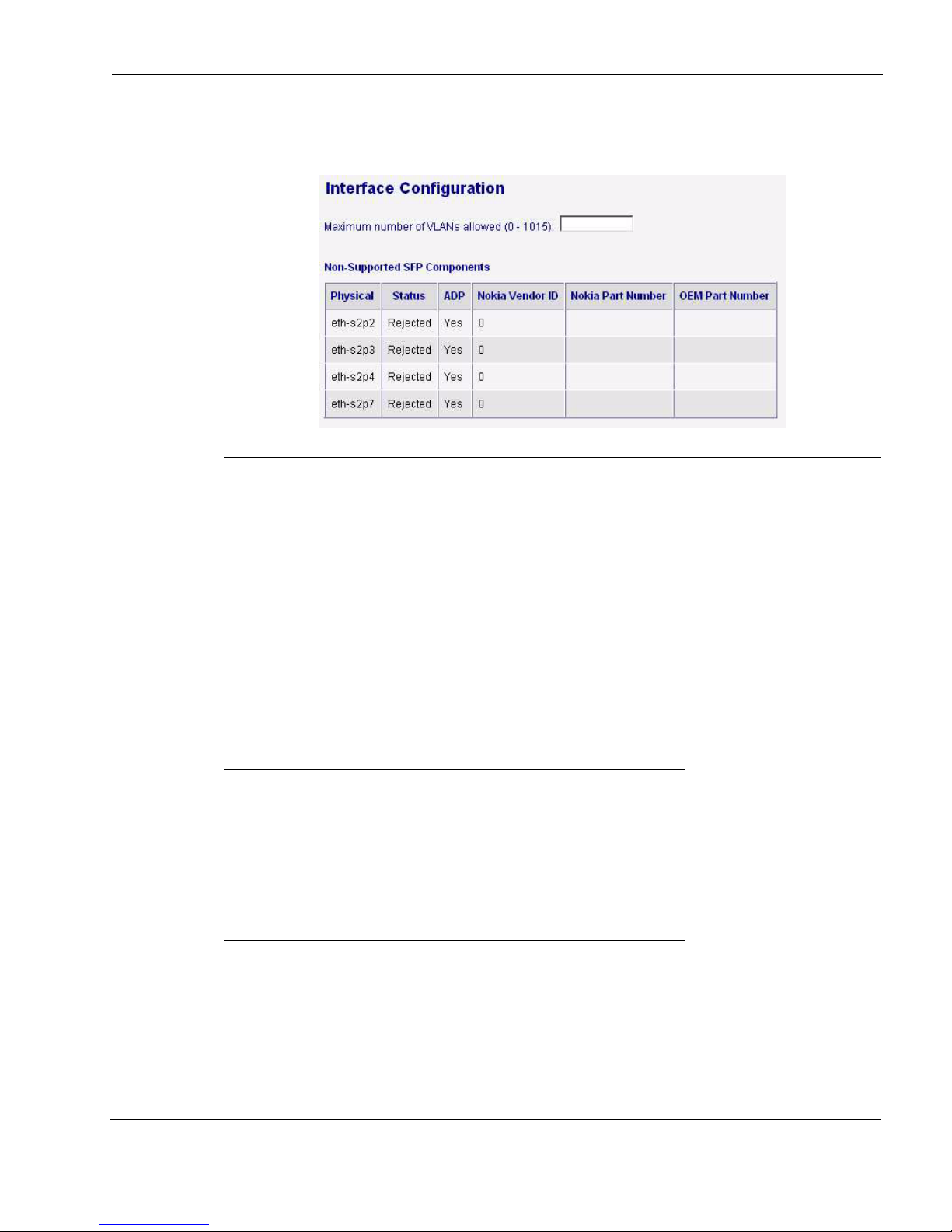
Identifying ADP Module and Transceiver Types with Latch Lever Color Codes
Note
of rejected interfaces on the Interface Configuration page in Check Point Network Voyager, as
shown in the following figure.
The Non-Supported Components table appears only if you have ADP transceivers installed
that are not supported by Check Point.
Identifying ADP Module and Transceiver Types with Latch
Lever Color Codes
To identify the types of ADP modules and transceivers you are using, refer to the color of the
latch levers as described in the following table.
Table 9 Identifying ADP Modules and Transceivers
Type Latch lever color
RJ-45 Gigabit Ethernet ADP modules Yellow
Gigabit Ethernet short range Black
Gigabit Ethernet long range Blue
10 Gigabit Ethernet short range Beige
10 Gigabit Ethernet long range Blue
Check Point ADP Module LED Reference Information
All Check Point IP1280 ADP modules provide two LEDs for each port to indicate Link and
Activity status. For information about the LEDs, see Figure 20 on page 73.
IP1280 Security Platform Installation Guide 75
Page 76

6 About IP1280 Appliance ADP Services Modules
Note
Configuring Check Point IPSO for IP1280 ADP Interfaces
This section includes information about configuring Check Point IPSO to use the interfaces on a
Check Point ADP module. To help you understand the implications of installing an ADP
module, it provides an example of the steps you might perform to install an ADP module in an
IP1280 appliance running the Virtual Router Redundancy Protocol (VRRP).
Effect on Interfaces
When you install ADP modules, Check Point IPSO automatically creates interface names for the
ADP interfaces and changes the existing interface names and configuration information, as
described below:
If you install an ADP module in an IP1280 appliance, the names and configuration
information for all the interfaces previously installed in an affected slot become invalid.
These changes can affect any features or protocols that use the existing interfaces or their
addresses, including the following:
Dynamic routing protocols
Multicast routing protocols
Static routing configuration
VRRP
IP clustering
Transparent mode
Link aggregation
Link redundancy
Traffic management/QoS
After you install an ADP module, reconfigure any protocols and features that used the
removed interfaces to use the ADP interfaces. Reassign IP addresses from the removed
interfaces to the ADP interfaces as appropriate.
Check Point ADP Module Interface Names for IP1280 Appliances
ADP module interface naming conventions differ from those for PMC NICs
The twelve ports on your ADP module are named as follows:
For slot 1:
eth-s1p1, eth-s1p2, eth-s1p3, eth-s1p4, eth-s1p5, eth-s1p6, eth-s1p7, eth-s1p8, eth-s1p9, eths1p10, eth-s1p11, eth-s1p12
For slot 2:
76 IP1280 Security Platform Installation Guide
Page 77

Configuring Check Point IPSO for IP1280 ADP Interfaces
eth-s2p1, eth-s2p2, eth-s2p3, eth-s2p4, eth-s2p5, eth-s2p6, eth-s2p7, eth-s2p8, eth-s2p9, eths2p10, eth-s2p11, eth-s2p12
Since the ADP interface names are not exactly the same as other PMC NIC interface names, you
need to reconfigure your appliance when you replace PMC NICs with an ADP module or an
ADP module with PMC NICs.
Configuring Network Topology with an IP1280 Appliance
There are several constraints that are relevant to your network topology after you install an ADP
module in an IP1280 appliance that are also relevant to the interaction of ADP interfaces and
NIC interfaces.
When you install an ADP module in an IP1280 appliance, Check Point recommends that you
configure your network so that your appliance does not forward traffic between ADP interfaces
and PMC NIC interfaces even if the NIC interfaces are Gigabit Ethernet. Using a configuration
of this type can significantly degrade throughput due to the need for packets to traverse multiple
PC backplane buses.
When you install an ADP module in an IP1280 appliance, the network processor in the module
performs all VPN encryption and decryption, even for VPN packets that are sent through PMC
NIC interfaces. The built-in Check Point encryption accelerator continues to accelerate IKE
traffic but does not perform any other processing. If VPN traffic is sent through a NIC interface,
throughput is negatively affected because the packets must transit the IP1280 appliance
backplane to reach the network processor in the ADP module. Check Point recommends that
you configure your VPNs to use only ADP interfaces to avoid this performance loss.
Configuration Example with VRRP
This example describes the steps required to install an ADP module in an IP1280 appliance with
VRRP configured. The following figure shows the Interface Configuration page of the platform
before an ADP module is installed.
IP1280 Security Platform Installation Guide 77
Page 78
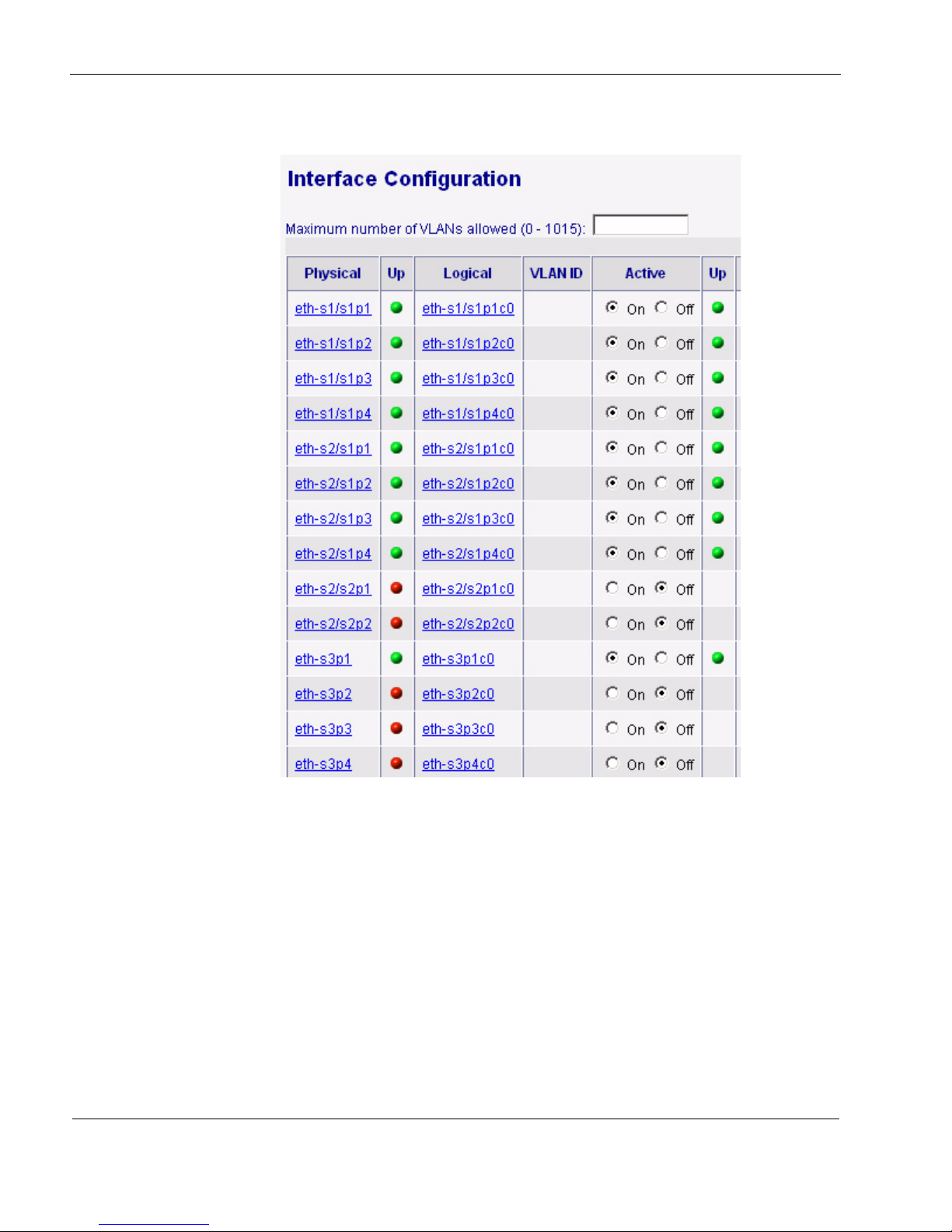
6 About IP1280 Appliance ADP Services Modules
Interfaces are installed in slots 1, 2, and 3.
For this example, legacy monitored-circuit VRRP is enabled and configured with these settings:
Interface eth-s1/s1p1c0 is assigned the IP address 10.1.1.1 (not shown) and uses 10.1.1.99 as
the VRRP backup address.
Interface eth-s1/s1p2c0 backs up interface eth-s1/s1p1c0.
78 IP1280 Security Platform Installation Guide
Page 79
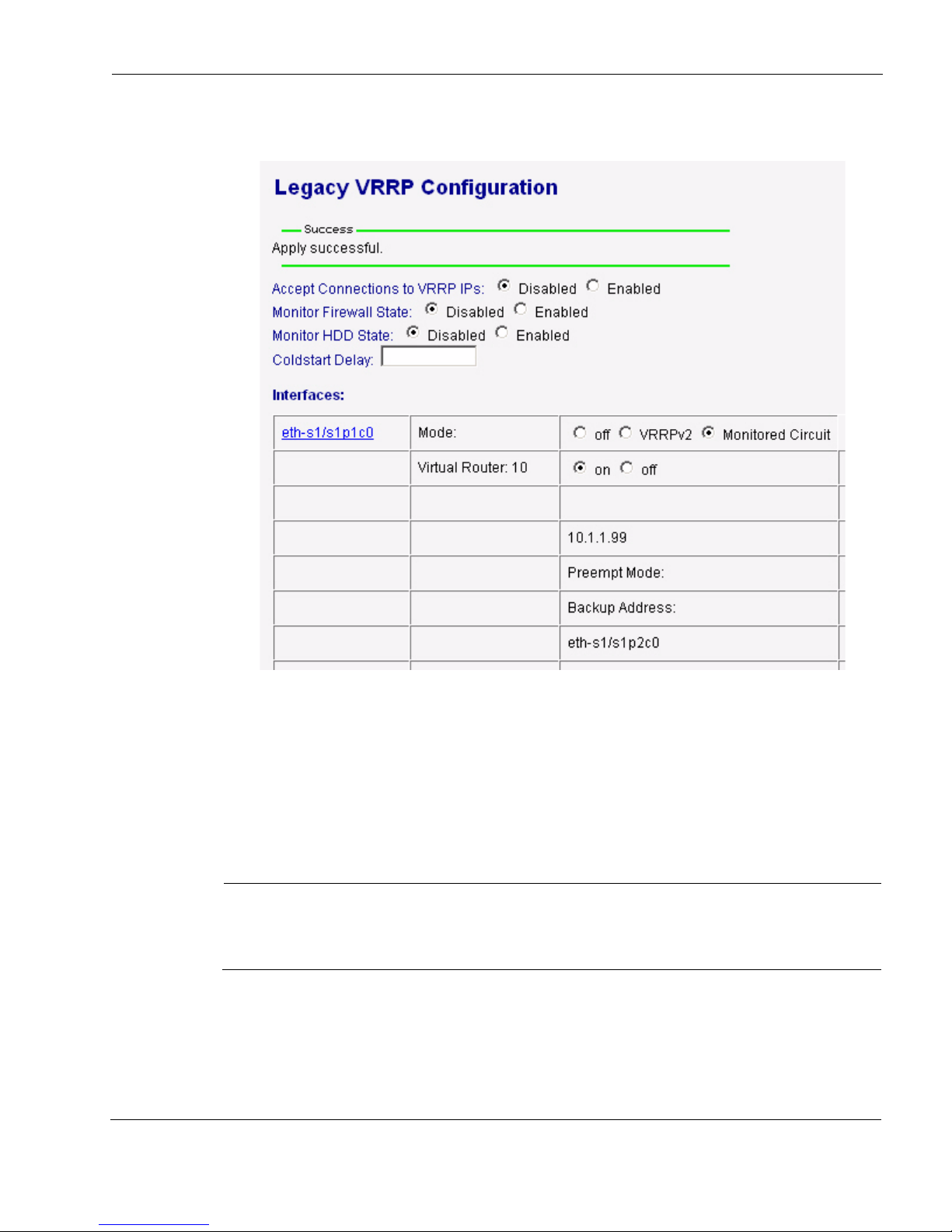
Configuring Check Point IPSO for IP1280 ADP Interfaces
Note
The following figure shows the VRRP configuration:
The rest of this section describes how to reconfigure the interfaces and VRRP to accommodate
the ADP interfaces.
Deleting VRRP Configurations
After you physically remove PMC NIC card carriers that you are replacing with ADP modules,
you need to delete the configuration information for those interfaces. If VRRP is active at that
time, you will not be able to delete the configuration information for the interfaces used by
VRRP. Therefore, you should begin by deleting the existing VRRP configuration.
It is best to perform the procedures in this section on the VRRP backup system first. When
the installation is complete, the upgraded system can become the new master while you
upgrade the original master.
IP1280 Security Platform Installation Guide 79
Page 80

6 About IP1280 Appliance ADP Services Modules
Reconfiguring Interfaces
After you install the ADP module, you need to reconfigure interface information as described
below.
To reconfigure interfaces for ADP modules
1. Log into the appliance using Check Point Network Voyager.
2. Navigate to the Interface Configuration page.
The removed interfaces are still listed on this page, and you see a blue indicator next to each
of them in the Up column.
Also notice that the ADP logical interfaces are named eth-s2p1c0 through eth-s2p12c0:
80 IP1280 Security Platform Installation Guide
Page 81
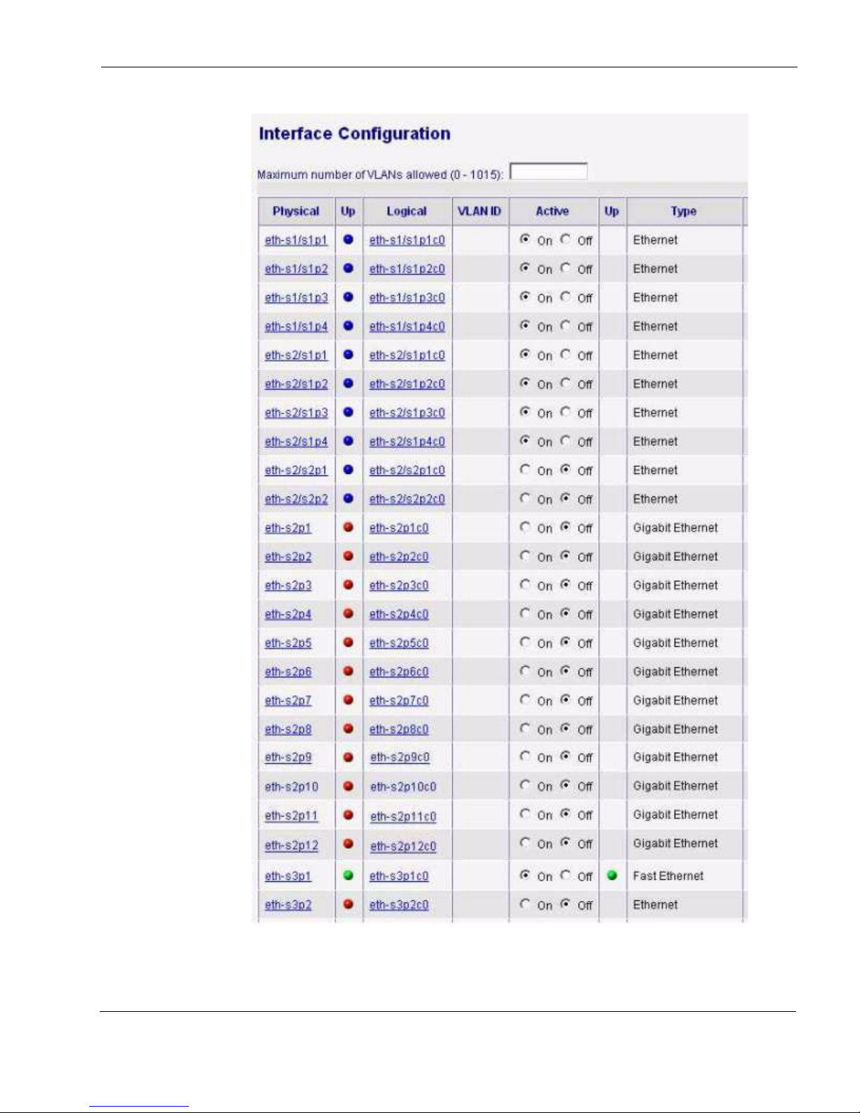
Configuring Check Point IPSO for IP1280 ADP Interfaces
IP1280 Security Platform Installation Guide 81
Page 82
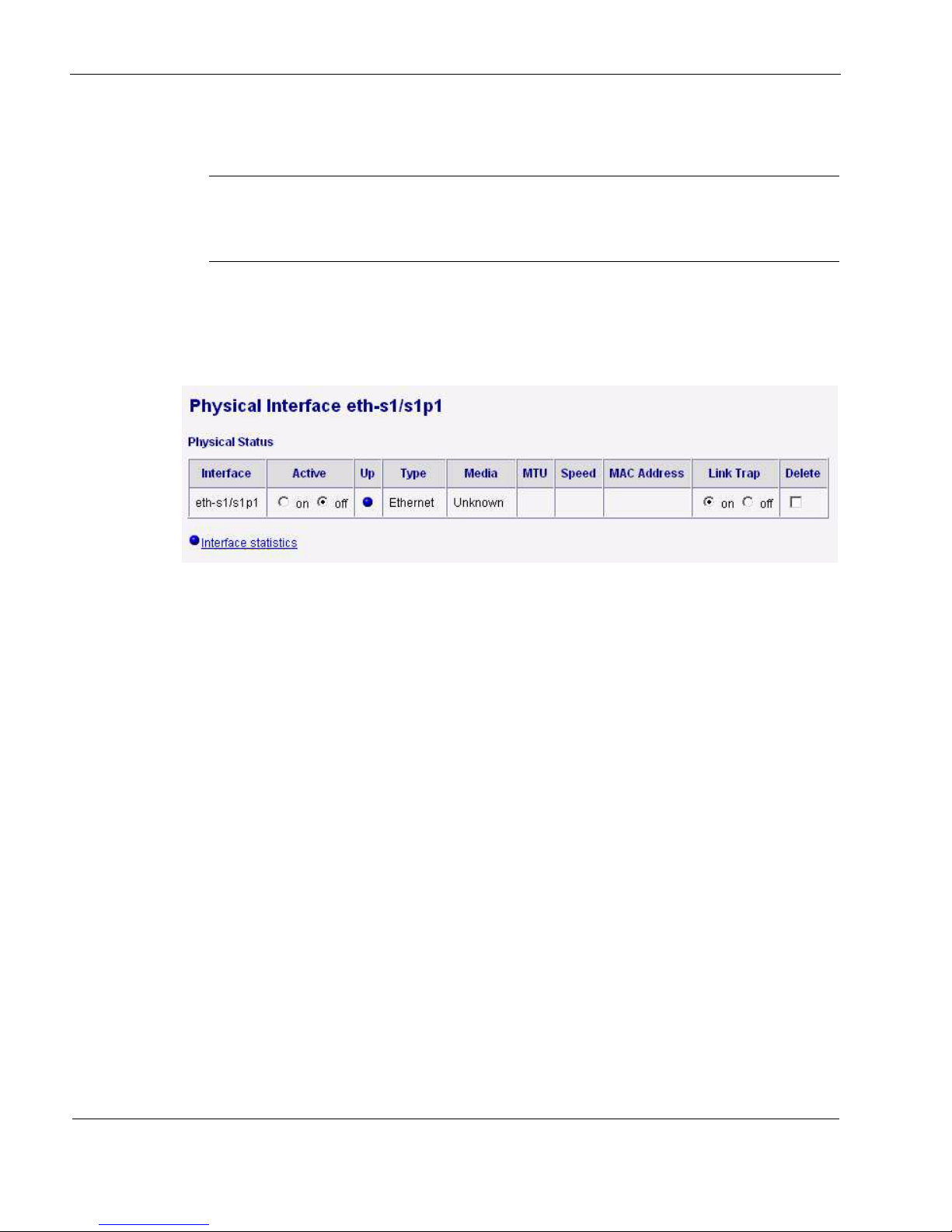
6 About IP1280 Appliance ADP Services Modules
Note
3. Delete the interface names and configuration information for each interface you removed by
following the remaining steps in this procedure.
To delete an interface used by VRRP or IP clustering, you must first disable the feature
that uses the interface. This is why you deleted the VRRP configuration before you
installed the ADP module.
4. Click a physical interface name.
Check Point Network Voyager displays the Physical Configuration page for that interface.
5. In the Physical Status area, click the Delete check box.
6. Click Apply.
7. Delete the configuration information for the rest of interfaces that you removed by restarting
this procedure at step 2.
8. When you have deleted the configuration information for all the interfaces that you
removed, click Save.
82 IP1280 Security Platform Installation Guide
Page 83
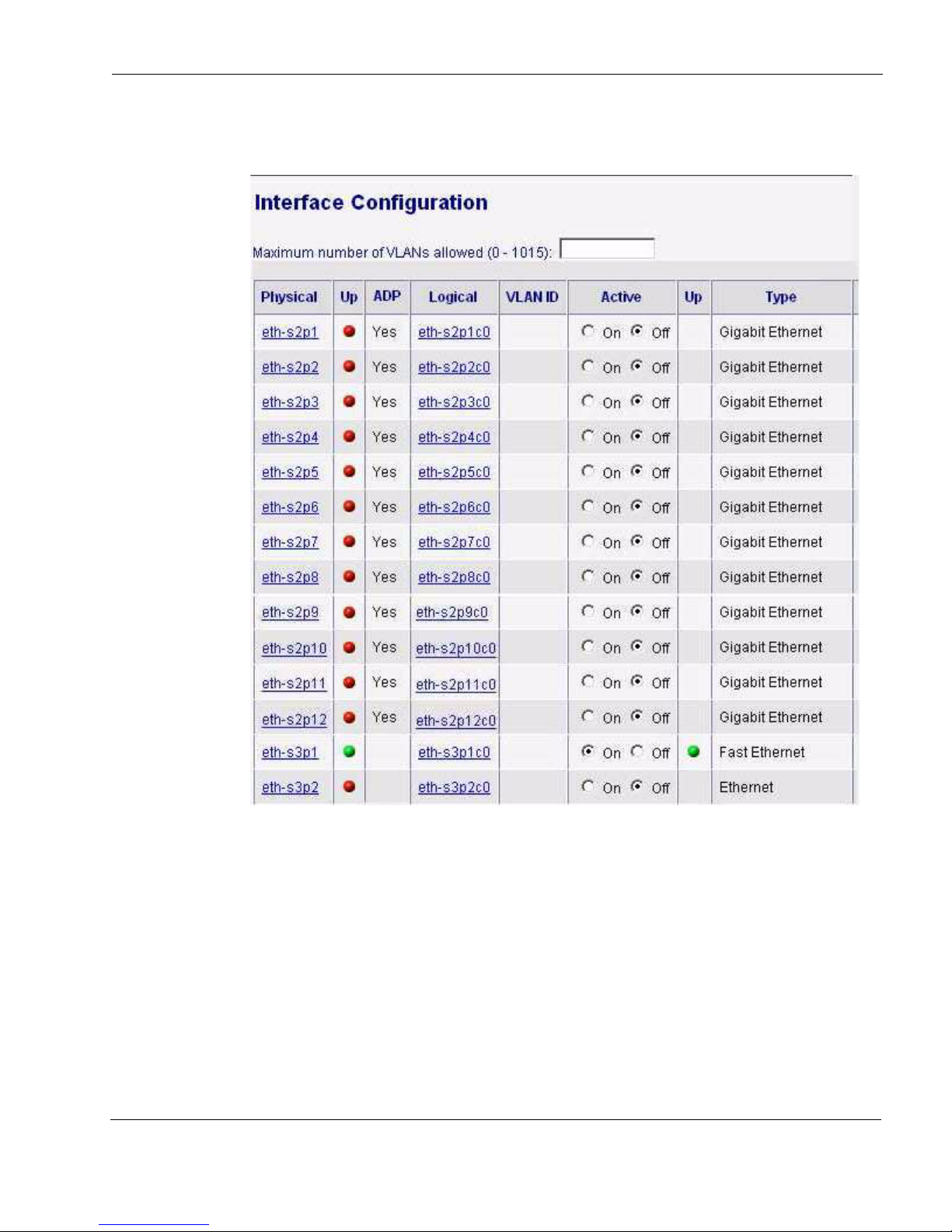
Configuring Check Point IPSO for IP1280 ADP Interfaces
The following figure shows the example system after the configuration information for all of
the removed interfaces has been deleted:
9. If appropriate, configure the ADP interfaces to use the IP addresses previously assigned to
the removed interfaces.
In this example, you need to assign the address 10.1.1.1 to the new interface eth-s2p1c0.
Reconfiguring VRRP
After you finish reconfiguring interfaces, you need to reconfigure any protocols and features
that used the removed interfaces to use the ADP interfaces.
In this example, you need to recreate the VRRP configuration using the new interfaces
IP1280 Security Platform Installation Guide 83
Page 84
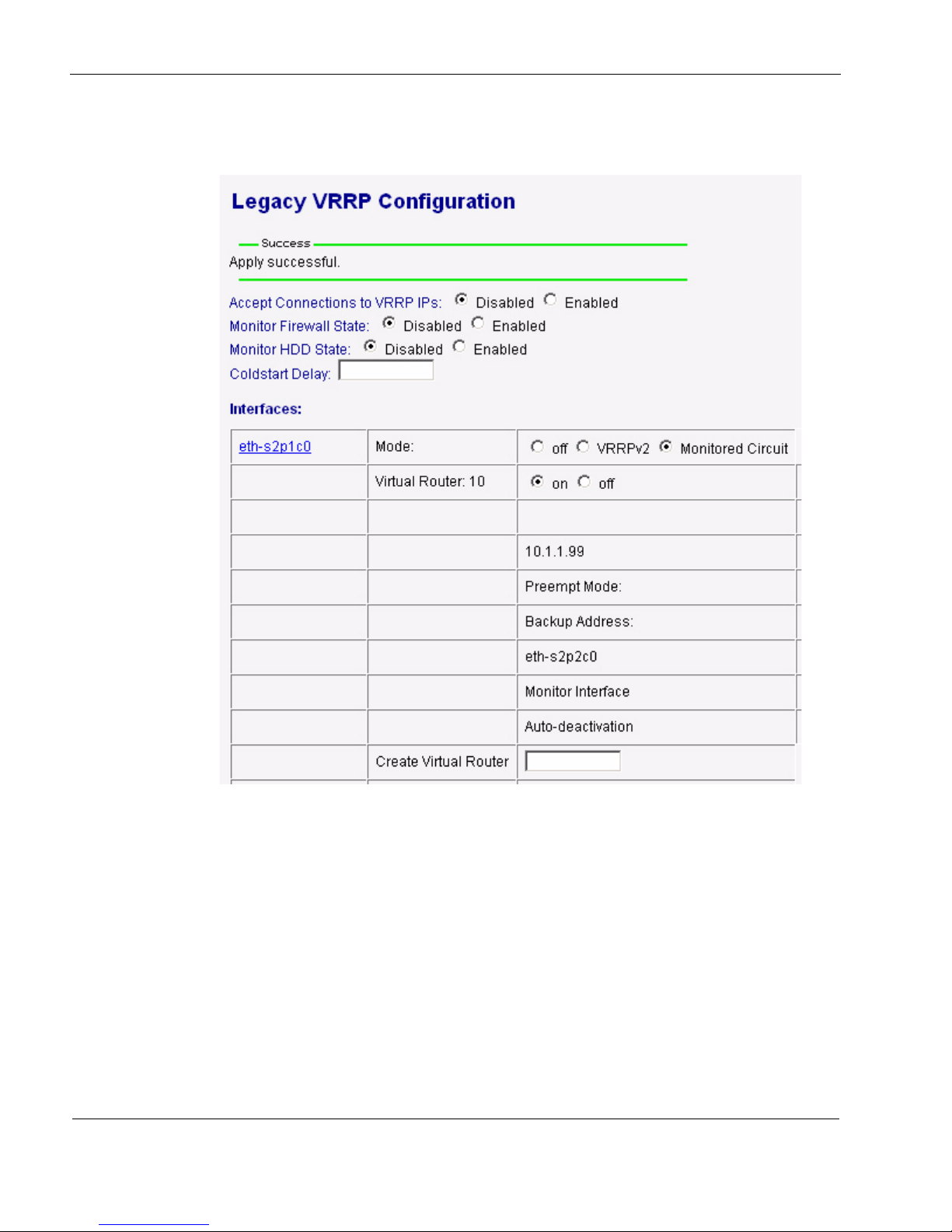
6 About IP1280 Appliance ADP Services Modules
eth-s2p1c0 and eth-s2p2c0. The following figure shows the example system after you
recreate the VRRP configuration using the new interfaces:
84 IP1280 Security Platform Installation Guide
Page 85

7 Installing and Replacing Components
Caution
Other than Network Interface Cards
(NICs) and Accelerated Data Path
(ADP) Services Modules
This chapter provides information about how to install or replace orderable parts other than
network interface cards (NICs) and Accelerated Data Path (ADP) services modules in your
Check Point IP1280 appliance. The following topics are covered:
Replacing the Check Point Encryption Accelerator Card
Installing or Replacing Hard-Disk Drives
Installing a PC Card
Replacing the Compact Flash Memory Card
Replacing or Upgrading Memory
Installing or Replacing a Fan Unit
Installing or Replacing a Power Supply
Replacing the Motherboard Battery
For information about how to add or replace NICs and ADP modules, see Chapter 4, “Installing
and Replacing Network Interface Cards and ADP Services Modules.”
You should have a working knowledge of networking equipment before you attempt to service
an IP1280. Limit service of the appliance to the procedures described in this chapter.
To protect the IP1280 and the memory modules from electrostatic discharge damage,
make sure you are properly grounded before you touch these components. Use a
grounding wrist strap and follow the instructions provided with the wrist strap before
you handle the components or open the appliance. The grounding plug on the front of
the appliance (shown in Figure 1 on page 17) provides a chassis grounding point. If
you do not have a grounding wrist strap, make sure you are properly grounded before
you touch any electronic component.
IP1280 Security Platform Installation Guide 85
Page 86

7 Installing and Replacing Components Other than Network Interface Cards (NICs) and Accelerated Data Path
Caution
Note
Replacing the Check Point Encryption Accelerator Card
The IP1280 comes with the Check Point encryption accelerator card preinstalled as part of its
base bundle to further enhance VPN performance. The accelerator card provides high-speed
cryptographic processing that enhances VPN performance.
The IP1280 appliance uses a PMC format accelerator card. The accelerator card has no external
connections and requires no cables. The accelerator card software package is part of Check Point
IPSO, so the appliance automatically detects and configures the card.
Use Check Point Network Voyager to configure your software applications to make use of the
available hardware accelerator. For information about how to configure software applications,
see “Configuring Software to Use Hardware Acceleration” on page 88.
This section describes how to install an accelerator card.
To install the Check Point encryption accelerator card
To install a Check Point encryption accelerator card, you need:
Physical access to the appliance
The Check Point encryption accelerator card and installation kit
Phillips-head screwdriver
Four screws (included in kit)
Grounding wrist strap (included in kit)
To avoid potential equipment malfunction, Check Point recommends that you obtain
encryption accelerator cards only from Check Point or authorized resellers. For further
information, see the Check Point Web site at www.checkpoint.com.
Because power to an IP1280 is automatically disconnected when the chassis assembly is
opened, you do not need to manually disconnect the power for this procedure. Any servicing
of the appliance, however, should be completed with the chassis assembly fully removed
from the appliance.
1. Use Check Point Network Voyager or the CLI to perform an orderly shutdown of the
IP1280.
For information about how to access Check Point Network Voyager and the related
reference materials, see “Using Check Point Network Voyager” on page 42.
2. Press the power switches, located on each power supply at the back of the appliance, to turn
off power to the appliance.
86 IP1280 Security Platform Installation Guide
Page 87
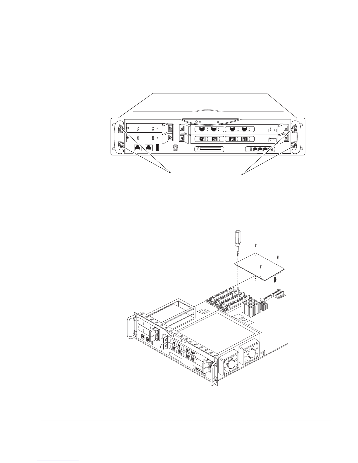
Replacing the Check Point Encryption Accelerator Card
Note
IP1280
RESET
00616a.1
CONSOLE AUX AUX2
HDD B
SLOT 3
SLOT 2
SLOT 1
HDD A
HOT SWAP
HOT SWAP
POWER
ACTIVITY
HARD DRIVE
STATUS
HOT SWAP
HOT SWAP
POWER
ACTIVITY
HARD DRIVE
STATUS
SLOT 4
1000BaseT
PC CARD
1
2
3
4
SUB SLOT 1 SUB SLOT 2
POWER
READY REQUEST
HOT SWAP
FIO CARRIER
1000B-LX
ACT
LINK
SUB SLOT 1 SUB SLOT 2
POWER
READY REQUEST
HOT SWAP
FIO CARRIER
1000B-LX
ACT
LINK
V2
1000BaseT
ACT
LINK
ACT
LINK
V2
1000BaseT
ACT
LINK
ACT
LINK
Chassis tray assembly screws
00659a
IP1280
R
ESE
T
C
O
N
S
O
L
E
A
U
X
A
U
X
2
H
D
D
B
S
L
O
T
3S
L
OT
2
H
D
D
A
H
O
T
S
W
A
P
H
O
T
S
W
A
P
P
O
W
E
R
A
C
T
I
V
I
T
Y
H
A
R
D
D
R
I
V
E
S
T
A
T
U
S
H
O
T
S
W
A
P
H
O
T
S
W
A
P
P
O
W
E
R
A
C
T
I
V
I
T
Y
H
A
R
D
D
R
I
V
E
S
T
A
T
U
S
S
L
OT
4
1000BaseT
1
2
3
4
SLO
T 1
A
C
T
A
C
T
S
T
A
T
LINK
S
U
B
S
L
O
T
1
S
U
B
S
L
O
T
2
P
O
W
E
R
R
E
A
D
Y
R
E
Q
U
E
S
T
H
O
T
S
W
A
P
F
I
O
C
A
R
R
I
E
R
1000B-LX
A
C
T
L
I
N
K
S
U
B
S
L
O
T
1
S
U
B
S
L
O
T
2
P
O
W
E
R
R
E
A
D
Y
R
E
Q
U
E
S
T
H
O
T
S
W
A
P
F
I
O
C
A
R
R
I
E
R
1000B-LX
A
C
T
L
I
N
K
V2
1000BaseT
ACT
LIN
K
AC
T
LI
NK
V2
1000BaseT
A
CT
LI
NK
A
CT
LINK
Check Point encryption accelerator card
Make sure that you turn off both power supplies.
3. Loosen the four front panel retaining screws.
4. Slide the chassis tray assembly forward, press and tray release lever, and completely remove
the tray from the appliance.
5. Install the encryption accelerator card as shown in the following graphic, press the right side
of the card to fully seat the connector, and secure the four screws included in the kit.
IP1280 Security Platform Installation Guide 87
Page 88

7 Installing and Replacing Components Other than Network Interface Cards (NICs) and Accelerated Data Path
6. Slide the chassis assembly back into the appliance until it clicks into place.
7. Resecure the chassis assembly retaining screws.
8. Press the power switches, located on each power supply at the back of the appliance, to turn
on the power to the appliance.
Configuring Software to Use Hardware Acceleration
The Check Point encryption accelerator software package is part of the Check Point IPSO
operating system, so the appliance automatically detects and configures the Check Point
encryption accelerator card.
For the Check Point IP1280 appliances, SecureXL is on by default. After you install the Check
Point encryption accelerator card and reboot the appliance, SecureXL automatically uses the
Check Point encryption accelerator card for encryption acceleration. If you do not want to use
SecureXL for encryption acceleration, use the Check Point cpconfig utility to disable SecureXL.
You can also configure the IP1280 appliances to use the Check Point encryption accelerator card
for IKE acceleration. When you enable IKE acceleration, the Check Point encryption accelerator
card performs cryptographic operations for IPsec tunnel negotiation.
To enable IKE acceleration
1. From the Check Point Network Voyager home page, click Security and Access
Configuration, then click IKE Acceleration.
For information about how to access Check Point Network Voyager and the related
reference materials, see “Using Check Point Network Voyager” on page 42.
2. On the IKE Acceleration page, click Register the module.
3. Click Apply.
4. The PKCS#11 token that enables IKE acceleration is registered with the Check Point
software on your appliance. After you register the module, you must install the Check Point
security policy on the firewall for the Check Point encryption accelerator card to perform
IKE acceleration.
Installing or Replacing Hard-Disk Drives
The Check Point disk-based IP1280 appliance supports up to two hard-disk drives with the
RAID-1 feature in the Check Point IPSO operating system. If the appliance has only one
hard-disk drive installed, it is in the top slot (slot A). You can add a second hard-disk drive into
the bottom slot (slot B) or replace the hard-disk drive in slot A.
This section describes how to remove and replace a failed hard-disk drive,
and how to add an optional second hard-disk drive to implement the RAID-1 feature.
Figure 21 shows the location of the hard-disk drives on the front of the IP1280.
88 IP1280 Security Platform Installation Guide
Page 89
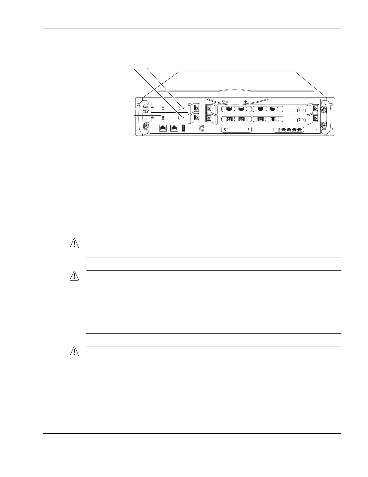
Figure 21 Location of Hard-Disk Drives
Caution
Caution
Caution
IP1280
RESET
00616a.1
CONSOLE AUX AUX2
HDD B
SLOT 3
SLOT 2
SLOT 1
HDD A
HOT SWAP
HOT SWAP
POWER
ACTIVITY
HARD DRIVE
STATUS
HOT SWAP
HOT SWAP
POWER
ACTIVITY
HARD DRIVE
STATUS
SLOT 4
1000BaseT
PC CARD
1
2
3
4
SUB SLOT 1 SUB SLOT 2
POWER
READY REQUEST
HOT SWAP
FIO CARRIER
1000B-LX
ACT
LINK
SUB SLOT 1 SUB SLOT 2
POWER
READY REQUEST
HOT SWAP
FIO CARRIER
1000B-LX
ACT
LINK
V2
1000BaseT
ACT
LINK
ACT
LINK
V2
1000BaseT
ACT
LINK
ACT
LINK
Hard-disk drive A
Hard-disk drive B
Hard-disk drive hot switches
Hard-Disk Drive Hot Swap Feature
A hot swap button is located on the front panel of each hard-disk drive. Pressing the hot swap
button allows you to hot swap hard-disk drives if you have configured and enabled RAID-1, and
the drive you are replacing is not being actively used by your IP1280.
Installing or Replacing Hard-Disk Drives
For more information about RAID-1, including configuration details, see Implementing Disk
Mirroring or RAID on a Network Security Appliance, which is available at the Check Point
Support Center at http://support.checkpoint.com/.
Hard-disk drives are susceptible to damage from shock. Handle them with care.
To protect the IP1280 and the memory modules from electrostatic discharge damage,
make sure you are properly grounded before you touch these components. Use a
grounding wrist strap and follow the instructions provided with the wrist strap before
you handle the components or open the appliance. The grounding plug on the front of
the appliance (shown in Figure 1 on page 17) provides a chassis grounding point. If
you do not have a grounding wrist strap, make sure you are properly grounded before
you touch any electronic component.
If you fail to use the following procedure when you remove the
hard-disk drive, the drive might become damaged or you might lose data.
IP1280 Security Platform Installation Guide 89
Page 90

7 Installing and Replacing Components Other than Network Interface Cards (NICs) and Accelerated Data Path
Caution
Caution
The operating system is disabled if all of the following occurs:
• Both hard-disk drive slots are occupied.
• The appliance is turned on.
• RAID-1 is not enabled.
• You press the hot swap button on the source hard-disk drive.
Before You Begin
To upgrade or replace a Check Point IP1280 appliance hard-disk drive, you need:
Physical access to the appliance
Check Point hard-disk drive kit and accompanying documentation
Phillips-head screwdriver
Removing and Replacing a Hard-Disk Drive
If you have RAID-1 configured on your Check Point IP1280 appliance, you can remove a failed
hard-disk drive without shutting down the appliance.
You must replace the hard-disk drive with a drive that has a capacity equal to or larger than the
drive you are replacing.
Back up your hard-disk drive files to a remote system on a regular basis. For backup and restore
procedures, see the documentation for Check Point Network Voyager or Check Point Horizon
Manager or the online help for either product.
To replace a hard-disk drive by using the hot-swap feature
For any active or RAID-1 synchronized hard-disk drive, you must use the hot swap
button, shown in Figure 4, before you remove or replace a hard-disk drive without
shutting the appliance down. If you replace or remove drives with the IP1280 shut off,
the RAID firmware will lose track of RAID volume data.
If the two hard-disk drives are fully synchronized, then either drive can be removed
using this procedure. If the two hard-disk drives are not fully synchronized, then only
the slave drive can be removed using this procedure.
90 IP1280 Security Platform Installation Guide
Page 91
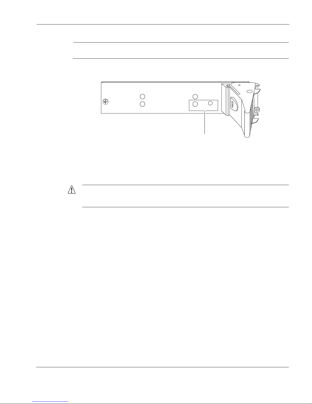
Installing or Replacing Hard-Disk Drives
Note
Caution
00621
ACTIVITY
HARD DRIVE
STATUS
HOT SWAP
READY
POWER
REQUEST
Hot swap button
and hot swap LED
You must have RAID-1 implemented to use the hot swap feature.
1. Locate the hard-disk drive to remove.
2. Press the hot swap button on the hard-disk drive with an open paper clip or similar device
and wait for the hot swap LED to illuminate solid blue.
3. Loosen the retaining screws on both sides of the hard-disk drive.
To avoid damage to the ejector and locking lever, loosen the retaining screw behind
each ejector and locking lever before you remove the hard-disk drive.
IP1280 Security Platform Installation Guide 91
Page 92
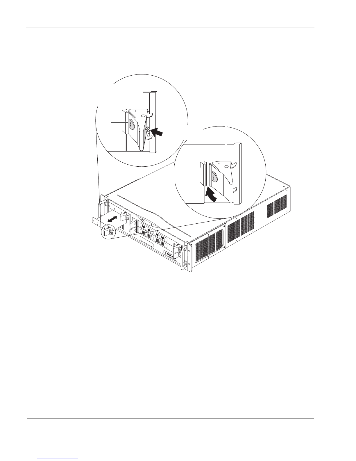
7 Installing and Replacing Components Other than Network Interface Cards (NICs) and Accelerated Data Path
00627a.1
I
P
1
2
8
0
RE
S
ET
C
O
N
S
O
L
E
A
U
X
A
U
X
2
H
D
D
B
S
L
O
T
3
S
L
O
T
2
S
L
O
T
1
H
D
D
A
S
L
O
T
4
HOT SWAP
H
O
T
S
W
A
P
P
O
W
E
R
A
C
T
I
V
I
T
Y
H
A
R
D
D
R
I
V
E
S
T
A
T
U
S
HOT SWAP
H
O
T
S
W
A
P
P
O
W
E
R
A
C
T
I
V
I
T
Y
H
A
R
D
D
R
I
V
E
S
T
A
T
U
S
1000BaseT
1
2
3
4
S
U
B
S
LO
T
1
S
U
B
S
L
OT
2
PO
W
E
R
RE
AD
Y
RE
Q
UE
S
T
H
O
T
S
W
A
P
F
I
O
C
AR
R
I
E
R
1000B-LX
ACT
LINK
S
U
B
SL
O
T
1
S
U
B
SL
O
T
2
PO
W
E
R
R
E
A
D
Y
R
EQ
U
E
S
T
H
O
T
S
W
A
P
F
I
O
C
AR
R
I
E
R
1000B-LX
ACT
LINK
V2
1000BaseT
A
C
T
L
I
N
K
A
C
T
L
I
N
K
V2
1000BaseT
A
C
T
L
I
N
K
A
C
T
L
I
N
K
Ejector and locking levers
Push red button to
disengage or
engage lock
Unscrew screw
to release
Release or lock
into place
4. When the status LED stops blinking, use your thumb or forefinger to press the ejector and
locking lever to eject the hard-disk drive from the chassis.
92 IP1280 Security Platform Installation Guide
Page 93
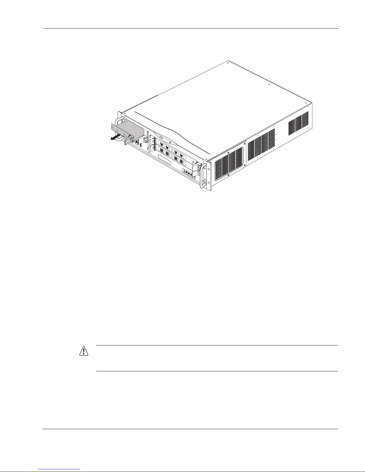
Installing or Replacing Hard-Disk Drives
Caution
00628a
I
P
1
2
8
0
R
ES
ET
C
O
N
S
O
L
E
A
U
X
A
U
X
2
H
D
D
B
S
L
O
T
3
S
L
O
T
2
S
L
O
T
1
H
D
D
A
HOT SWAP
HOT SWAP
POWER
ACTIVITY
HARD DRIVE
STATUS
S
L
O
T
4
HOT SWAP
HOT SWAP
POWER
ACTIVITY
HARD DRIVE
STATUS
1000BaseT
1
2
3
4
SU
B
S
L
OT
1
S
U
B
S
L
O
T
2
PO
W
E
R
R
E
A
D
Y
R
E
Q
U
ES
T
H
OT
S
W
A
P
F
I
O
C
A
RR
I
E
R
1000B-LX
ACT
LINK
S
U
B
S
L
OT
1
S
UB
S
L
O
T
2
PO
WE
R
R
EA
DY
R
E
QU
ES
T
HO
T
S
WA
P
F
IO
C
A
RR
IE
R
1000B-LX
ACT
LINK
V2
1000BaseT
A
C
T
L
I
N
K
A
C
T
L
I
N
K
V2
1000BaseT
A
C
T
L
I
N
K
A
C
T
L
I
N
K
5. Gently pull the hard-disk drive forward to remove it from the appliance.
6. Install a replacement hard-disk drive into the empty hard-disk drive bay.
7. Lock the hard-disk drive in place by pressing the ejector and locking lever.
8. Tighten the screws on both sides of the hard-disk drive.
9. Press the recessed hot swap button again to restore power to the hard-disk drive.
The IP1280 recognizes the new hard-disk drive.
10. Use Check Point Network Voyager or the CLI to implement RAID-1.
To remove a hard-disk drive without using the hot swap feature
1. Unless both of the following are true:
You are removing a hard-disk drive used as part of a RAID-1 implementation, and
The hard-disk drive is not active
you need to perform an orderly shutdown of your appliance before completing the rest of
this procedure.
2. Loosen the retaining screws on both sides of the hard-disk drive.
To avoid damage to the ejector and locking lever, loosen the retaining screw behind
each ejector and locking lever before you remove the hard-disk drive.
IP1280 Security Platform Installation Guide 93
Page 94
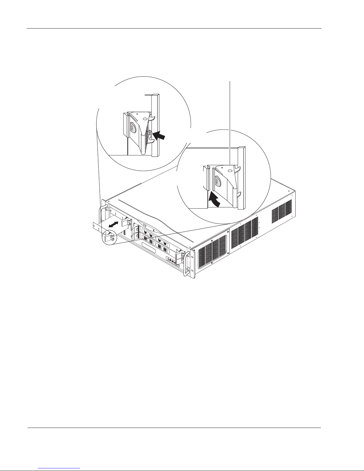
7 Installing and Replacing Components Other than Network Interface Cards (NICs) and Accelerated Data Path
00627a.1
I
P
1
2
8
0
R
E
SE
T
C
O
N
S
O
L
E
A
U
X
A
U
X
2
H
D
D
B
S
L
O
T
3
S
L
O
T
2
S
L
O
T
1
H
D
D
A
S
L
O
T
4
HOT SWAP
H
O
T
S
W
A
P
P
O
W
E
R
A
C
T
I
V
I
T
Y
H
A
R
D
D
R
I
V
E
S
T
A
T
U
S
HOT SWAP
H
O
T
S
W
A
P
P
O
W
E
R
A
C
T
I
V
I
T
Y
H
A
R
D
D
R
I
V
E
S
T
A
T
U
S
1000BaseT
1
2
3
4
S
UB
SL
O
T
1
S
UB
SL
O
T
2
P
O
W
E
R
R
E
A
D
Y
R
EQ
U
ES
T
H
O
T
S
W
A
P
FI
O
C
A
R
R
I
E
R
1000B-LX
ACT
LINK
S
U
B
S
L
O
T
1
S
U
B
S
LO
T
2
P
O
W
E
R
R
E
A
D
Y
R
E
Q
U
E
S
T
H
O
T
S
W
AP
F
IO
C
A
R
R
I
E
R
1000B-LX
ACT
LINK
V2
1000BaseT
A
C
T
L
I
N
K
A
C
T
L
I
N
K
V2
1000BaseT
A
C
T
L
I
N
K
A
C
T
L
I
N
K
Ejector and locking levers
Push red button to
disengage or
engage lock
Unscrew screw
to release
Release or lock
into place
3. Use your thumb or forefinger to press the ejector and locking lever on the hard-disk drive
that you are removing to eject the hard-disk drive from the chassis.
94 IP1280 Security Platform Installation Guide
Page 95
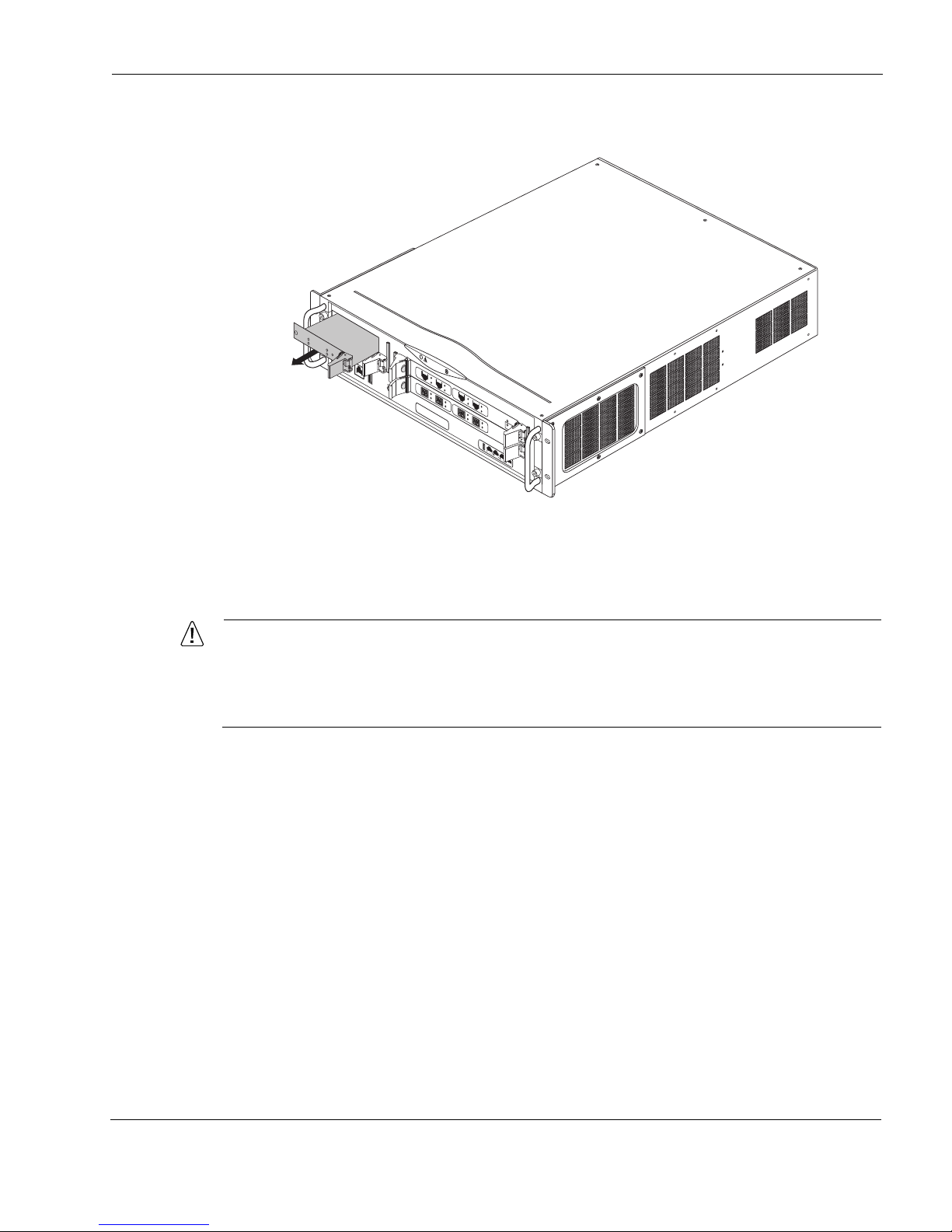
4. Gently pull the hard-disk drive forward to remove it from the appliance.
Caution
00628a
I
P
1
2
8
0
R
ESE
T
C
O
N
S
O
L
E
A
U
X
A
U
X
2
H
D
D
B
S
L
O
T
3
S
L
O
T
2
S
L
O
T
1
H
D
D
A
HOT SWAP
HOT SWAP
POWER
ACTIVITY
HARD DRIVE
STATUS
S
L
O
T
4
HOT SWAP
HOT SWAP
POWER
ACTIVITY
HARD DRIVE
STATUS
1000BaseT
1
2
3
4
SU
B
S
L
OT
1
S
U
B
S
L
O
T
2
P
OW
E
R
R
E
A
D
Y
R
E
Q
U
ES
T
H
OT
SW
AP
F
I
O
C
A
RR
I
ER
1000B-LX
A
CT
LINK
S
U
B
S
L
O
T
1
S
UB
S
L
O
T
2
PO
W
E
R
R
EA
D
Y
R
E
QU
ES
T
HO
T
S
WA
P
F
IO
C
A
RR
I
ER
1000B-LX
ACT
LINK
V2
1000BaseT
A
C
T
L
I
N
K
A
C
T
L
I
N
K
V2
1000BaseT
A
C
T
L
I
N
K
A
C
T
L
I
N
K
Installing a PC Card
5. Insert the new hard-disk drive until it locks into place.
The ejector and locking lever clicks into the locked position.
6. Tighten the retaining screws on both sides of the hard-disk drive.
If two disk drives are installed, the contents of the drive installed in the top slot or
location will be synchronized with the drive in the bottom slot (as long as the second
drive is not already identified with a different volume) as soon as the IP1280 is
rebooted.
Installing a PC Card
After you install a single-slot PCMCIA carrier card, which you can purchase from Check Point,
the IP1280 supports a PC card with 1-GB flash memory that Check Point offers with or without
system software included. You can use the carrier card in slot 3, which is located on the front
panel of the appliance, as shown in Figure 22.
Check Point supports only PC cards purchased from Check Point or Check Point-approved
resellers. For more information, see the Check Point Web site at www.checkpoint.com.
IP1280 Security Platform Installation Guide 95
Page 96
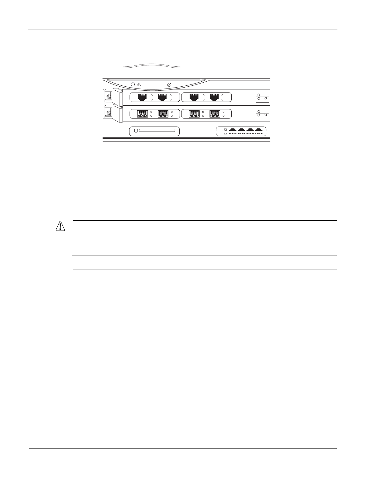
7 Installing and Replacing Components Other than Network Interface Cards (NICs) and Accelerated Data Path
Caution
Note
00617.1
SLOT 3
SLOT 2
SLOT 1
SLOT 4
1000BaseT
PC CARD
1
2
3
4
SUB SLOT 1 SUB SLOT 2
POWER
READY REQUEST
HOT SWAP
FIO CARRIER
1000B-LX
ACT
LINK
SUB SLOT 1 SUB SLOT 2
POWER
READY REQUEST
HOT SWAP
FIO CARRIER
1000B-LX
ACT
LINK
V2
1000BaseT
ACT
LINK
ACT
LINK
V2
1000BaseT
ACT
LINK
ACT
LINK
PC card slot
Figure 22 Slot 3 PC Card Location
To install the single-slot PCMCIA carrier card
To install a single-slot PCMCIA carrier card, you need:
Physical access to the appliance
A Check Point single-slot PCMCIA carrier card
Access to the appliance by using Check Point Network Voyager or the CLI
To avoid potential equipment malfunction, Check Point recommends that you obtain
flash-memory PC cards only from Check Point or authorized resellers. For further
information, see the Check Point Web site at www.checkpoint.com.
Because power to an IP1280 is automatically disconnected when the chassis assembly is
opened, you do not need to manually disconnect the power for this procedure. Any servicing
of the appliance, however, should be completed with the chassis assembly fully removed
from the appliance.
1. Use Check Point Network Voyager or the CLI to perform an orderly shutdown of the
IP1280.
For information about how to access Check Point Network Voyager and the related
reference materials, see “Using Check Point Network Voyager” on page 42.
96 IP1280 Security Platform Installation Guide
Page 97
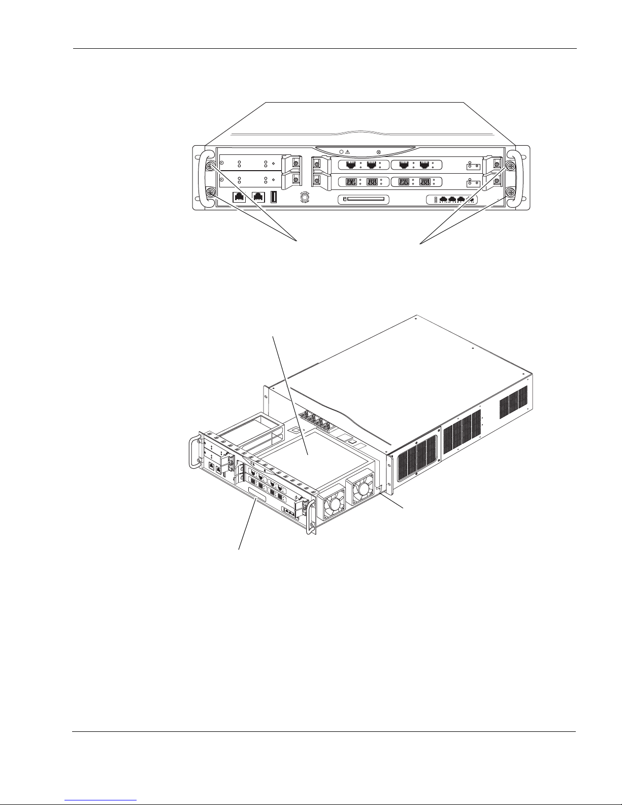
Installing a PC Card
IP1280
RESET
00616a.1
CONSOLE AUX AUX2
HDD B
SLOT 3
SLOT 2
SLOT 1
HDD A
HOT SWAP
HOT SWAP
POWER
ACTIVITY
HARD DRIVE
STATUS
HOT SWAP
HOT SWAP
POWER
ACTIVITY
HARD DRIVE
STATUS
SLOT 4
1000BaseT
PC CARD
1
2
3
4
SUB SLOT 1 SUB SLOT 2
POWER
READY REQUEST
HOT SWAP
FIO CARRIER
1000B-LX
ACT
LINK
SUB SLOT 1 SUB SLOT 2
POWER
READY REQUEST
HOT SWAP
FIO CARRIER
1000B-LX
ACT
LINK
V2
1000BaseT
ACT
LINK
ACT
LINK
V2
1000BaseT
ACT
LINK
ACT
LINK
Chassis tray assembly screws
IP1280
R
ES
E
T
C
O
N
S
O
L
E
A
U
X
A
U
X
2
H
D
D
B
S
L
O
T
3
S
L
O
T
2
S
L
O
T
1
H
D
D
A
HO
T SWAP
H
O
T
S
W
A
P
P
O
W
E
R
A
C
T
I
V
I
T
Y
H
A
R
D
D
R
I
V
E
S
T
A
T
U
S
HOT SWAP
H
O
T
S
W
A
P
P
O
W
E
R
A
C
T
I
V
I
T
Y
H
A
R
D
D
R
I
V
E
S
T
A
T
U
S
S
L
O
T
4
00637a
1000BaseT
1
2
3
4
SUB SLOT 1
SUB SLOT 2
POWER
READY
REQUEST
HOT SWAP
FIO CARRIER
1000B-LX
A
CT
L
IN
K
SUB SLOT 1
SUB SLOT 2
POWER
READY
REQUEST
HOT SWAP
FIO CARRIER
1000B-LX
A
CT
L
IN
K
V2
1000BaseT
A
C
T
L
I
N
K
A
C
T
L
I
N
K
V2
1000BaseT
A
C
T
L
I
N
K
A
C
T
L
I
N
K
PMC carrier shield
Slot 3
Tray release lever
2. Loosen the four front panel retaining screws.
3. Slide the chassis tray assembly forward, press and tray release lever, and completely remove
the tray from the appliance.
4. Remove the six screw that secure the metal shield above the two PMC carriers and remove
the shield.
IP1280 Security Platform Installation Guide 97
Page 98
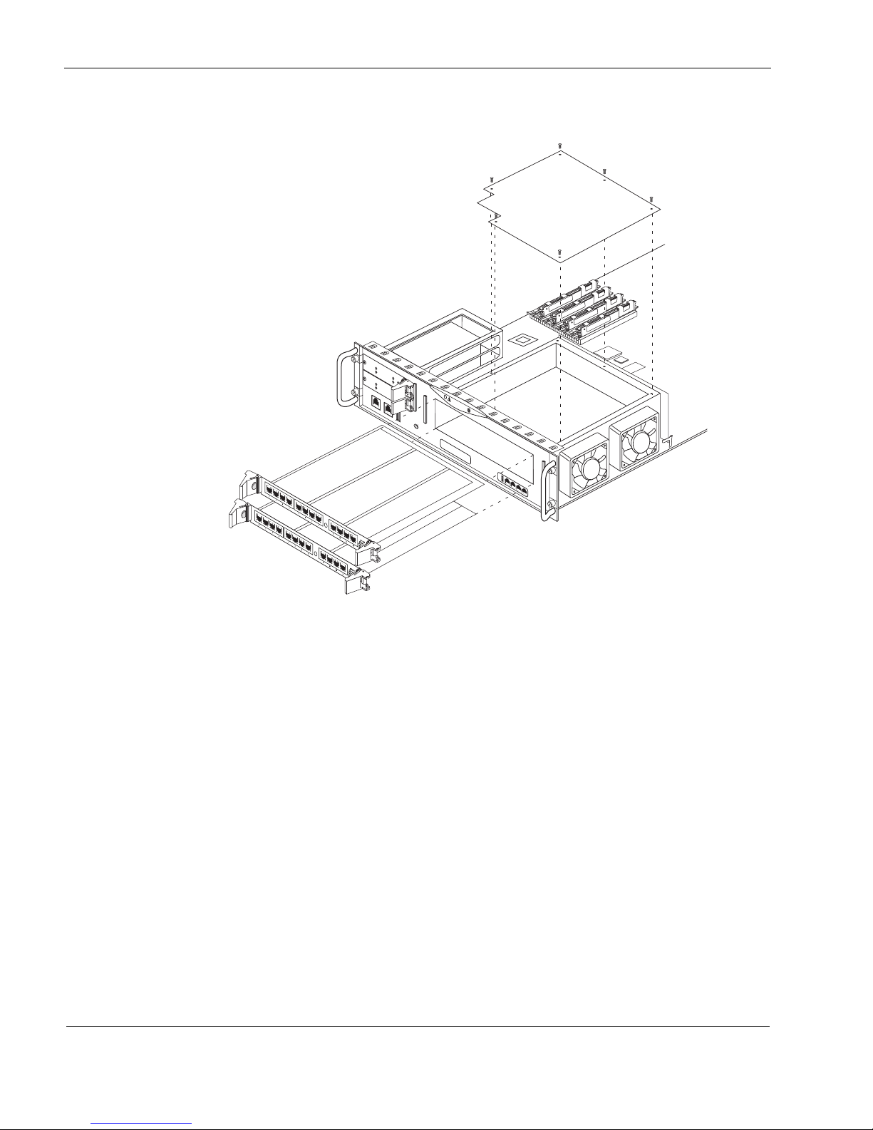
7 Installing and Replacing Components Other than Network Interface Cards (NICs) and Accelerated Data Path
I
P
1
2
8
0
RESET
C
O
N
S
O
L
E
A
U
X
A
U
X
2
H
D
D
B
S
L
O
T
3
S
L
O
T
2
H
D
D
A
H
O
T
S
W
A
P
H
O
T
S
W
A
P
P
O
W
E
R
A
C
T
I
V
I
T
Y
H
A
R
D
D
R
I
V
E
S
T
A
T
U
S
H
O
T
S
W
A
P
H
O
T
S
W
A
P
P
O
W
E
R
A
C
T
I
V
I
T
Y
H
A
R
D
D
R
I
V
E
S
T
A
T
U
S
S
L
O
T
4
00654a.1
1000BaseT
1
2
3
4
Remove PMC carriers
Remove six
screws and
PMC carrier
shield
5. Remove any installed PMC carriers so that both slot 1 and slot 2 are not occupied.
6. Remove the two front bezel screws and remove the slot 3 filler panel or installed NIC.
98 IP1280 Security Platform Installation Guide
Page 99
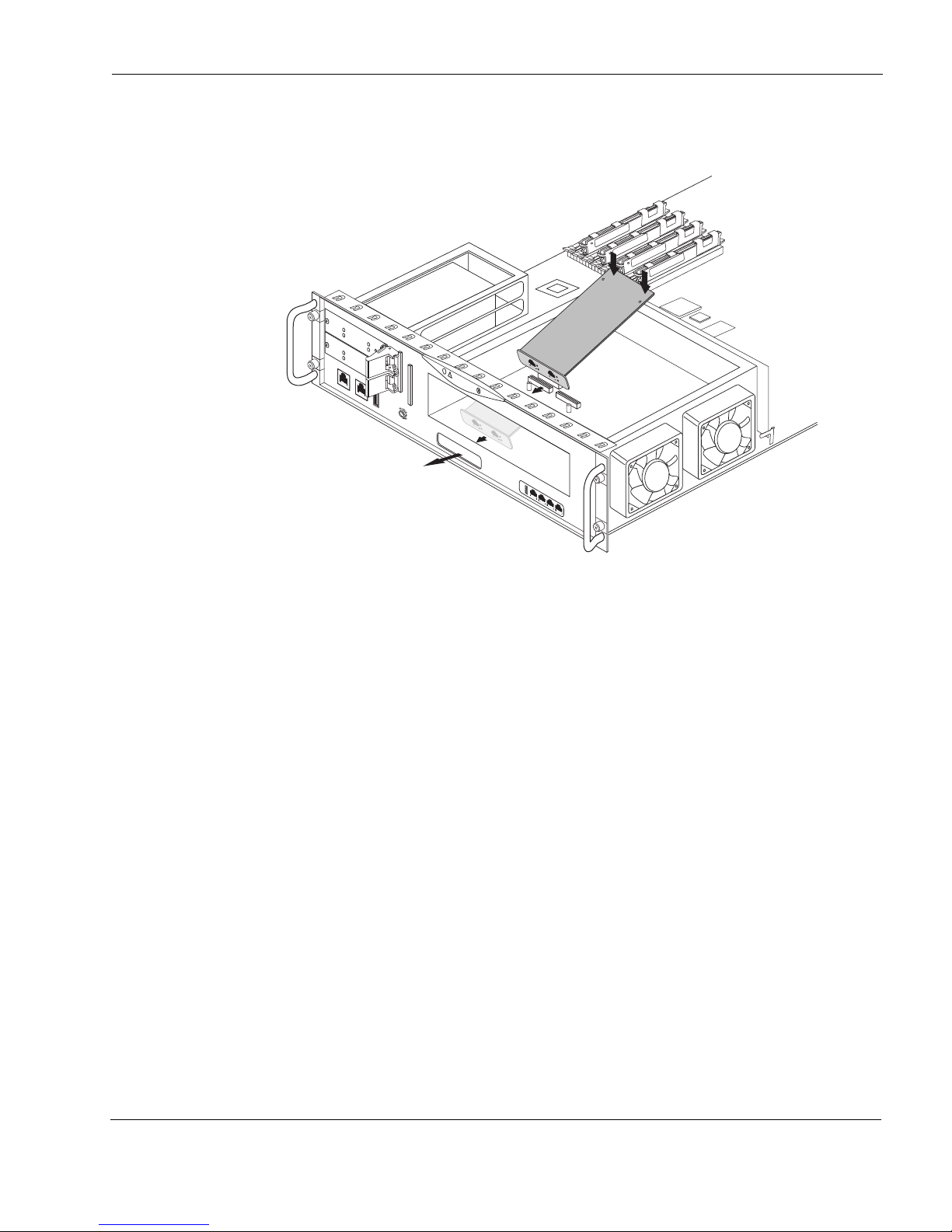
Installing a PC Card
00657a.2
IP1280
R
E
S
E
T
C
O
N
S
O
L
E
A
U
X
A
U
X
2
H
D
D
B
S
L
O
T
3
SLOT 2
S
L
O
T
1
H
D
D
A
H
O
T
S
W
A
P
HOT SW
AP
P
OW
ER
ACTIVIT
Y
H
A
RD DRIVE
STA
TUS
H
O
T
S
W
A
P
HOT
S
WA
P
POW
ER
ACTIVITY
H
AR
D
DR
IVE
S
TAT
U
S
S
L
O
T
4
1000BaseT
1
2
3
4
L
INK
A
CT
V
2
L
INK
A
CT
1
0
0
0
B
a
s
e
T
LI
NK
AC
T
V
2
LINK
ACT
1
0
0
0
B
a
s
e
T
7. Raise the back end of the PCMCIA carrier card approximately 45 degrees as you insert the
front end into slot 3 in the front panel.
IP1280 Security Platform Installation Guide 99
Page 100
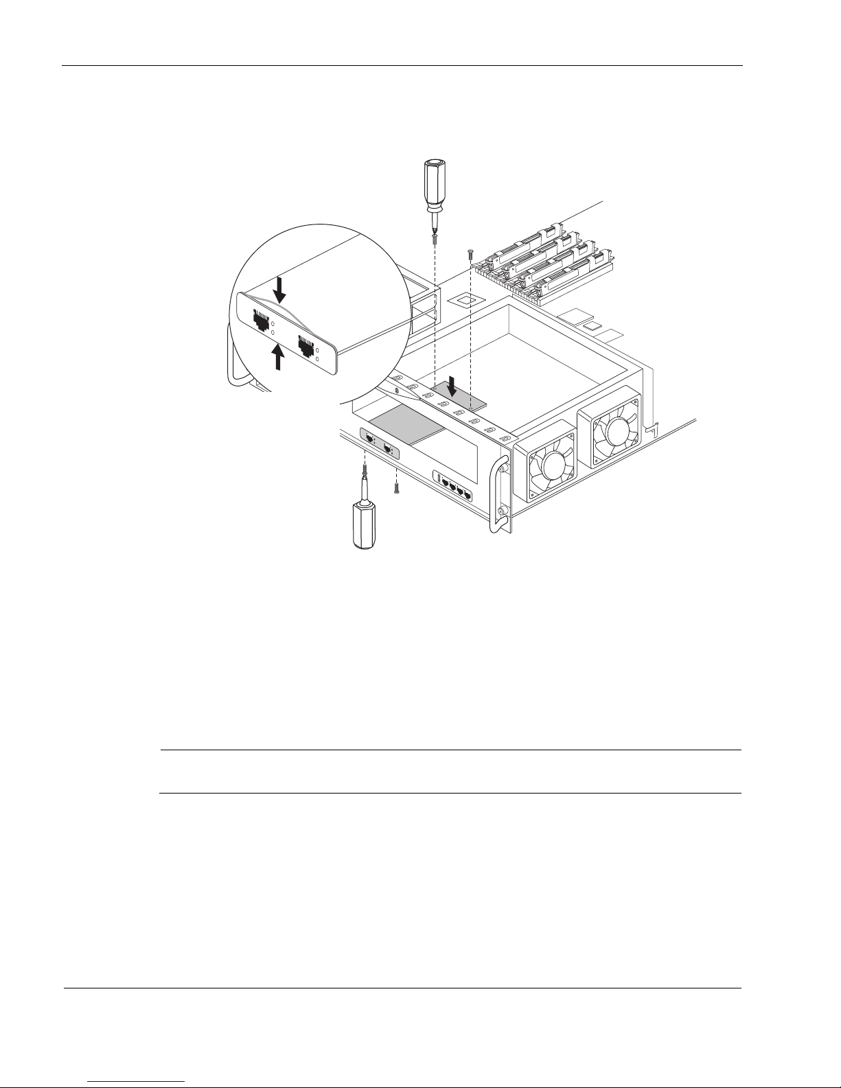
7 Installing and Replacing Components Other than Network Interface Cards (NICs) and Accelerated Data Path
Note
00644a.2
IP1280
R
E
S
E
T
C
ONSOLE
A
UX
A
UX2
HDD B
S
L
OT 3
S
LO
T 2
S
LO
T 1
HDD A
HO
T
S
W
A
P
H
O
T SW
AP
POW
ER
A
C
TIV
I
T
Y
HA
RD
D
RIVE
S
T
A
TU
S
H
O
T
S
W
A
P
H
O
T
S
W
AP
PO
WE
R
A
C
TIVI
T
Y
H
AR
D
DR
IVE
S
T
A
TU
S
S
L
OT 4
1000BaseT
1
2
3
4
PC CARD
1000BaseT
LINK
A
C
T
LINK
A
CT
1000BaseT
L
INK
ACT
L
INK
A
CT
Take care that the
EMI gasket doesn’t
roll back during
carrier card
installation
Arrows indicate
locations where the
gasket might roll back
Secure the two rear
carrier card screws
Reinstall the two bezel screws
8. Being careful to push down only where the motherboard connectors are located, press the
back end of the carrier card down into the connectors until it is fully seated.
100 IP1280 Security Platform Installation Guide
9. Secure the back end of the carrier card with the two screws provided with the kit.
10. Secure the front end of the carrier card by replacing the two front bezel screws that you
removed previously.
11. Slide the chassis assembly back into the appliance until it clicks into place.
12. Resecure the chassis assembly retaining screws.
13. Press the power switches, located on each power supply at the back of the appliance, to turn
on the power to the appliance.
Make sure that you turn on both power supplies.
To install the PC card
1. Insert the PC card into the PC card slot until it snaps in place.
2. Press gently on the card until it is firmly seated in the slot.
The eject button to the left of the slot should be flush with the card.
 Loading...