

Page 1
QUICK SETUP
Series ATP
www.cppumps.com
Tool Requirements
Hex Wrenches: 1/8”, 5/32”, 3/16”
Open-End Wrenches: 7/16”, 5/8”, 7/8”, 1”
Leg Assembly and Pump Attachment
1. Unpack pump stand assembly, and ensure that all pieces are
supplied.
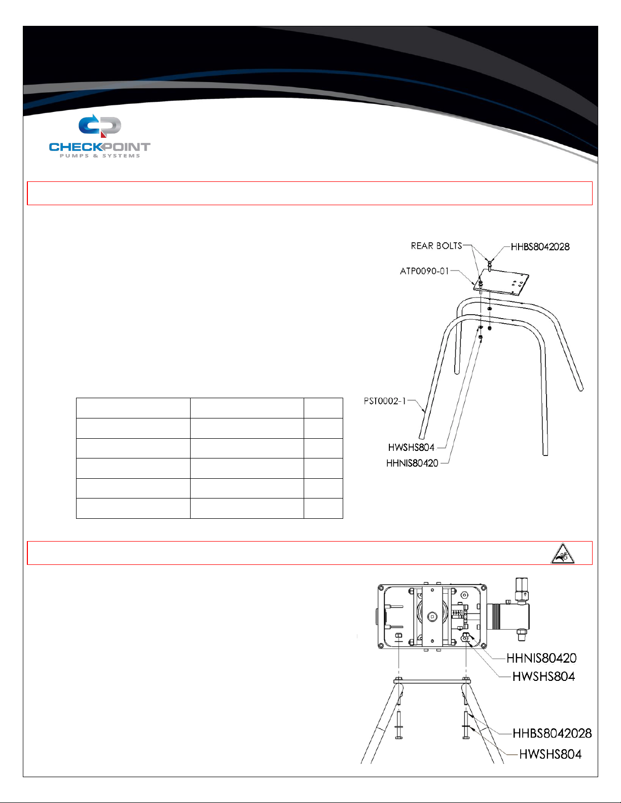
2. Place pump bracket (ATP0090-01) onto both legs. The four holes
near the edge of the bracket are located between the two legs (as
shown below).
3. Install the two rear bolts with washers through the pump bracket and
legs of the pump stand, and tighten the hex nuts.
PART #
DESCRIPTION
QTY.
ATP0090-01
PUMP BRACKET
1
HHBS8042028
HEXHEAD BOLT
4
HHNIS80420
HEX NUT
4
HWSHS804
FLAT WASHER
8
PST0002-1
LEG – SOLAR
2
WARNING: Ensure that you are wearing proper PPE before performing any action.
WARNING: Pinch points. Disconnect power before removing cover.
4. Remove the front cover from the pump drive.
5. Set the pump on the stand such that the four carriage-assembly boltheads line up in the stand clearance holes. Install the two front bolts
with washers from the underside of the pump through the legs and
into the pump drive housing, and tighten hex nuts.
6. Connect the suction line to the bottom check valve, and connect the
discharge line to the top check valve.
CP-QS-ATP
REV00 EFF. DATE: 1/9/2019
Page 1 of 2
Page 2
QUICK SETUP
Series ATP
www.cppumps.com
Chemical Flow Rate Adjustment
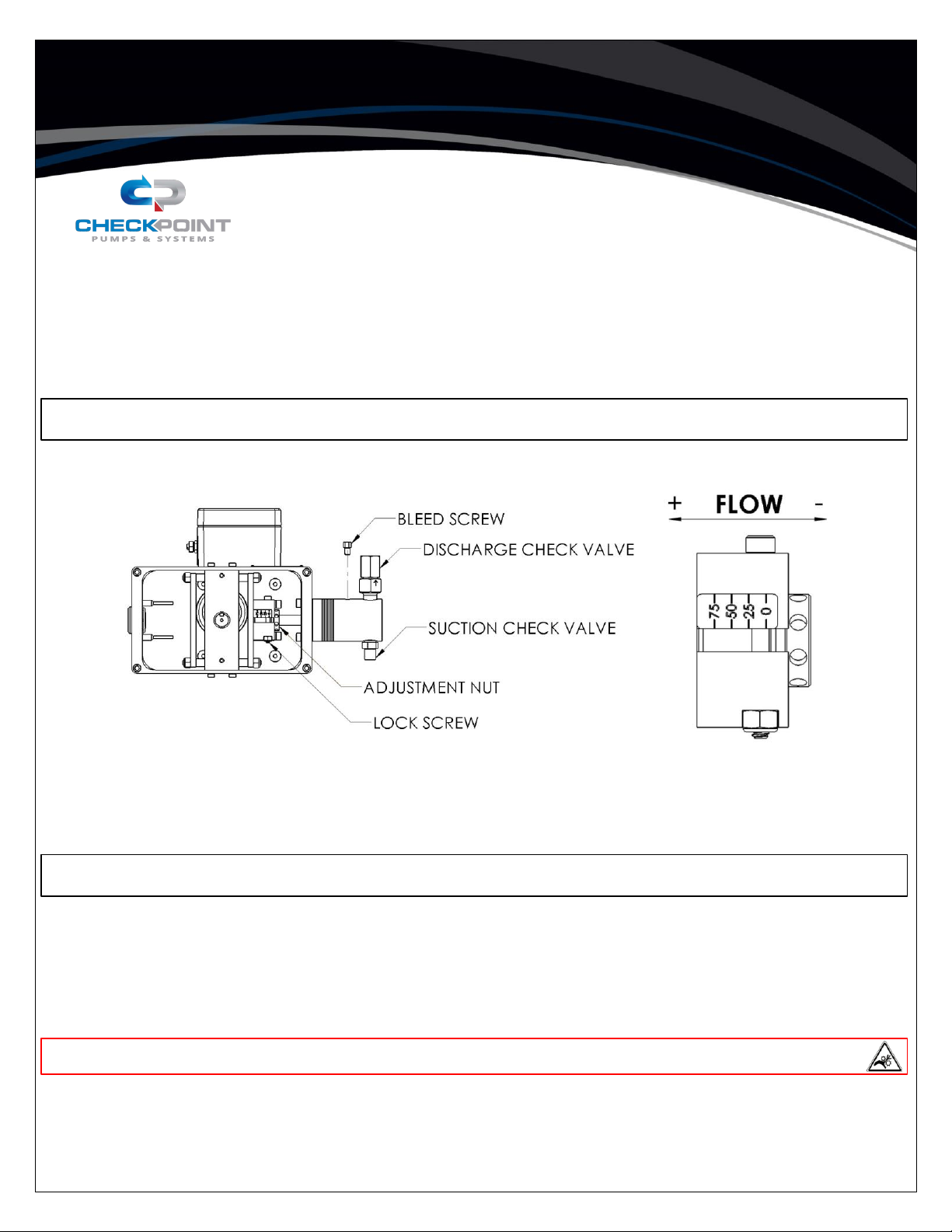
7. Loosen the lock screw on the adjustment block. Using the supplied adjustment tool, turn the adjustment nut to increase or
decrease the flow rate to the desired percentage, as indicated by the markings (refer to the flow charts to estimate position
based on your application).
CAUTION: Do not turn the adjustment nut to apply force below the 0% or above the 100% mark.
8. Re-tighten the lock screw on the adjustment block.
9. Reinstall the pump cover.
10. Connect the pump to the electrical service.
CAUTION: Ensure that the power source does not exceed the rating for the pump motor.
11. With fluid media present at the pump suction, loosen the bleed screw and discharge line at the discharge check outlet to
vent to atmosphere. Run the pump until all air trapped in the head is released. Stop the pump.
Re-tighten the discharge line and bleed screw.
12. Run a drawdown flow calibration. If the flow rate is correct, stop here. If the flow rate requires adjustment, continue.
13. Disconnect the power.
WARNING: Pinch points. Disconnect power before removing cover.
14. Remove the pump cover.
15. Return to Step 7. Repeat these steps until the target flow rate is achieved.
CP-QS-ATP
REV00 EFF. DATE: 1/9/2019
Page 2 of 2
 Loading...