

Page 1
DIGITAL FORCE GAUGE
00.0
NG
peak
Lb
OK +NG
OVERLOAD
ZERO
SEND PEAK
ON
OFF
00.0
NG
peak
Lb
OK +NG
OVERLOAD
DIGITAL FORCE GAUGE
ZERO
SEND PEAK
ON
OFF
DIGITAL FORCE GAUGE
00.0
NG
peak
Lb
OK +NG
OVERLOAD
ZERO
SEND PEAK
ON
OFF
2 YEAR WARRANTY (RESTRICTIONS APPLY)
Imada, Inc. warrants its products to the original purchaser to be free from defects
in workmanship and material under normal use and proper maintenance for two
years (one year for adapters, attachments and cables) from original purchase. This
warranty shall not be effective if the product has been subject to overload, shock
load, misuse, negligence,accident or repairs attempted by others than Imada, Inc.
During the warranty period, we will, at our option, either repair or replace defective products.Please call our customer service department for a return authorization
number and return the defective product to us with freight prepaid.
The foregoing warranty constitutes the SOLE AND EXCLUSIVE WARRANTY, and we
hereby disclaim all other warranties, express, statutory or implied, applicable to the
products and/or software, including but not limited to all implied warranties of merchantability, fitness, non-infringement, results, accuracy, security and freedom from
computer virus. In no event shall Imada, Inc. and/or its affiliated companies be liable
for any incidental,consequential or punitive damages in connection with the use of its
products and/or software.
Digital Force Gauge
04/07 Specifications subject to change without notice.
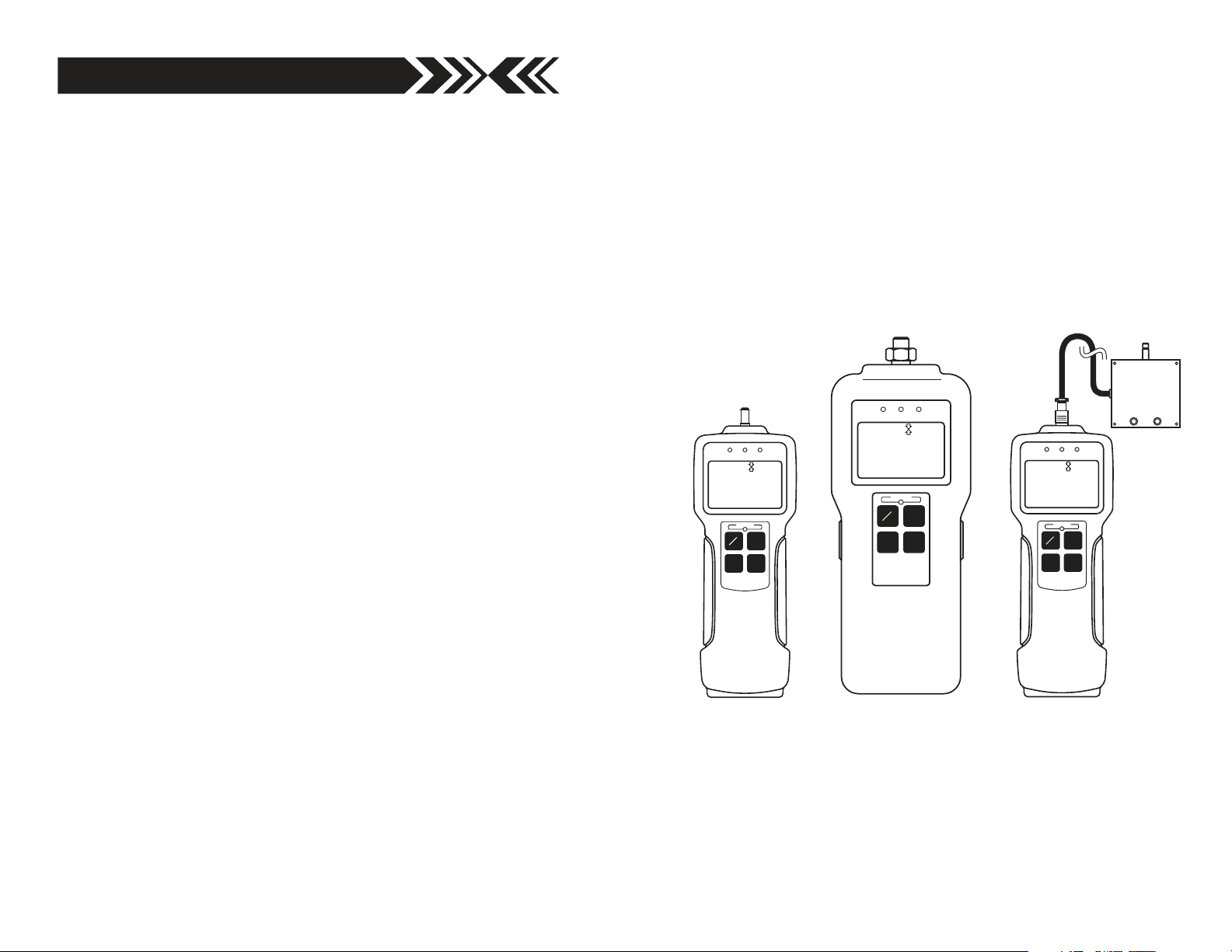
Z Series
USB Models: ZP, ZPH and ZPS
INSTRUCTION MANUAL
Page 2
INTRODUCTION
DIGITAL FORCE GAUGE
00.0
NGLbOK +NG
OVERLOAD
ZERO
SEND PEAK
ON
OFF
DIGITAL FORCE GA
UGE
00.0
NG
Lb
OK +NG
OVERLOAD
ZER
O
SEND
PEAK
ON
OFF
Imada Z Series are state-of-the-art high performance, digital force
gauges which offer USB output, giant, easy-to-read LCD displays
and high/low setpoints with color-coded LED indicators for go/no
go testing. These force gauges store up to 1,000 data values in
memory, which can be transmitted using USB or RS-232 or output formats.
The real time measuring mode is used to display force transients.
Peak measuring mode captures the peak force achieved during a
test. Select measuring units from lbf(ozf), kgf(gf), and N.
Save As… – modify file path and file name. Choose File
1
Folder and file name setup or press the save button and
select Save the data to new.csv file.
Clear Memory – all data in force gauge memory cleared.
Choose Option
Top Most – ZP Logger is locked in the foreground; uncheck to
run ZP Logger in the background. Choose Option
Track/Peak Indicator – Displays peak or real time measuring
2
Erase all of memory
2
TopMost
3
mode. Press Peak key on gauge to select desired mode.
IMPORTANT
1. WARNING!! Test samples and fixtures can break or shatter,
wear eye and body protection to avoid injury.
2. WARNING!! REGARDLESS of whether the unit is ON or OFF,
DO NOT exceed the capacity of the gauge. At 110% of the
rated capacity, the overload LED indicator flashes to warn.
NEVER exceed 200% of the rated capacity, or the load cell will
be damaged. Avoid shock load.
3. When mounting Z Series, use M4 mounting screws with a
maximum insertion depth of 5 mm into the gauge. For high
capacity gauges (ZPH) use mounting hardware supplied only.
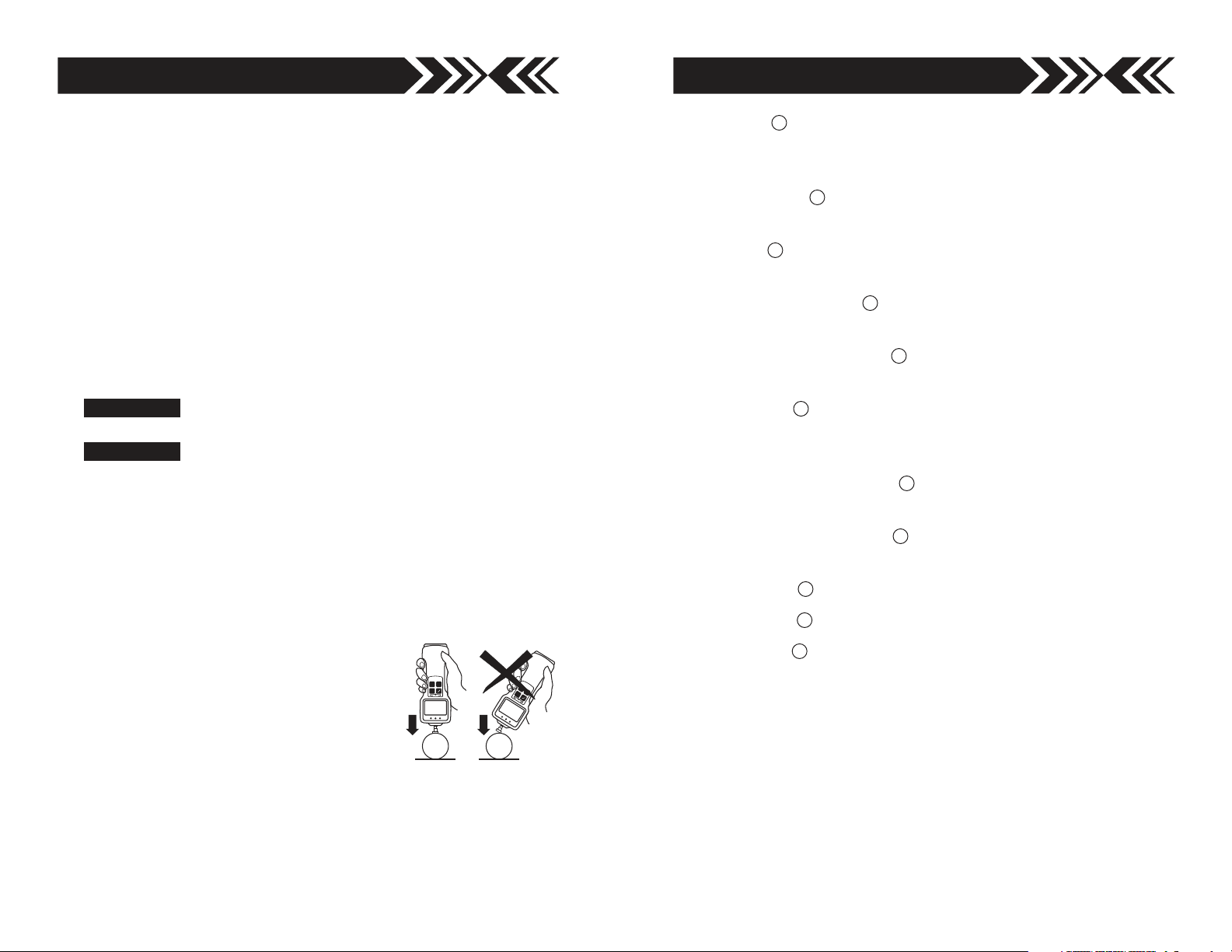
4. Measure in line tension and compression forces only. DO
NOT attempt to measure forces perpendicular to the measuring shaft –
damage to load cell and/or shaft may
result.
5. Hand tighten attachments only.
DO NOT use tools.
6. Make sure this gauge and all peripherals are powered down
before attaching any cables.
7. DO NOT disassemble the gauge. Disassembly voids warranty.
Online/Offline Indicator – Online is displayed when the force
4
gauge is interfaced to the computer through the USB port.
Zero Button – Press Zero on ZP Logger or gauge to tare the
5
weight of the attachment and shaft orientation. Zero also
clears peak reading.
Read Current Val. Button – Equivalent to pressing the Send
6
key on the gauge.
Read Memorized Button – Download and log all data from
7
gauge memory.
Clear Button – completely clear ZP Logger data pad.
Copy Button – copy ZP Logger data to the clipboard.
Save Button – Press Zero on ZP Logger or gauge to tare the
8
9
10
weight of the attachment and shaft orientation. Zero also
clears peak reading. From the list:
1. Select Save the data to new csv file to save a new CSV file to
the name and path specified.
2. Select Save the data to new row of existing csv file to modify
an existing CSV file by adding a new column of data. File
modified must agree with ZP Logger CSV format.
3. Select Folder and file name set up to modify the file path and
file name.
page 19page 2
Page 3
ZP Logger Operation
1. Click Start/Programs/Imada/ZP Logger
2. Turn on the gauge and confirm the USB
caption is visible on the gauge display.
3. Connect the ZP, ZPH or ZPS force gauge
to the computer with the USB cable provided.
4. Turn on the gauge. The ZP Logger Online/Offline indicator
should change to Online (blue).
If Indicator doesn’t change to Online, check:
USB cable
USB driver installation
Microsoft.NET Framework 1.1 installation.
If ZP Recorder software (optional) is running, it should be
closed.
Download Gauge Memory –
On startup of ZP Logger press
the Read Memorized button to
download and log gauge memory to ZP Logger. This feature is
disabled if Read Current Val button or the Send key on gauge are
pressed or enabled if the Clear
key is pressed. Data can then be
saved by using the File menu or
Save button.
Record Gauge Data –
6
Press the Send key on the gauge
or the Read Current Val button
on the ZP Logger. Peak or real
time data goes into internal
gauge memory as well as ZP Logger.
7
1 2
3 4
5
6 7
8 9 10
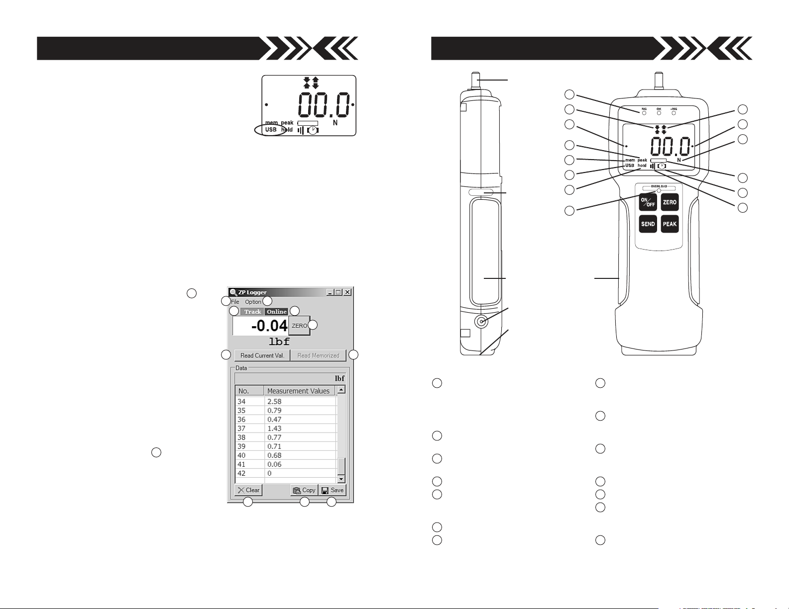
MEASURING SHAFT
WARRANTY
SEAL
NON-SLIP RUBBER GRIP
AC ADAPTER/CHARGER
RECEPTACLE
COMMUNICATION PORT
USB, RS-232 &
±2VDC ANALOG
ZP, ZPH, and ZPS (with remote sensor) use the same keypad.
1
Programmable Setpoint LED’s
When high-low setpoints are set,
LED indicates below (-NG), within
(OK), or above set point value
(+NG).
2
Compression icon
Indicates compression measurement.
3
Tension icon
Indicates tension measurement.
4
Reverse +/– values
5
Auto Zero Reset icon
Programmable auto zero reset
duration
6
Auto Memory - Peak Reset icon
7
USB output icon
1
2 3
9
6
7
10
14
8
Battery icon
Flashes when Ni-MH cells need
charging.
9
PEAK icon
Displays continuously when peak
function is active.
10
HOLD icon
Displays when external hold signal
is active or SEND button is pressed.
11
Alarm Icon
12
Auto Power Off icon
13
Units icon
Displays selected measuring units.
(ozf, Lbf, gf, kgf, or N)
14
Overload Indicator
Flashes at 110% of rated capacity.
45
13
8
12
11
page 3page 18
Page 4

PREPARATION
To connect the remote sensor to the ZPS display unit, rotate the
round connector to find the matching groove, then push it in
until positive connection is made. To disconnect, first slide the
ribbed cover of the connector back, then pull out the connector
(DO NOT ROTATE THE CONNECTOR WHEN PULLING OUT).
RIBBED COVER
ROTATE CONNECTOR TO FIND THE
GROOVE
REMOTE SENSORS
PUSH IN UNTIL IT MAKES A
POSITIVE CONNECTION
SLIDE BACK RIBBED COVER,
THEN PULL OUT CONNECTOR
BOX TYPE
DPU both tension and compression
Low capacity: Box Type (±0.2% F.S.; ±1 LSD)
High capacity: S Type (±0.2% F.S.; ±1 LSD)
LM
LM compression only (±0.5% F.S.; ±1 LSD)
'S' TYPE
IMPORTANT: Load applying surface must be flat
OPERATION
Selecting Units
Press to turn on the gauge. The LCD display briefly shows the
capacity of the gauge and then zero with a measuring unit (facto-
ry setup is lbf). If you want to change to other units:
1. Turn off the gauge.
2. Press again while holding to enter Power-Off program-
ming mode (CF9 flashes with solid nn0).
3. Press to display U-03 with a unit, then press or to
Installing Microsoft .NET Framework
Microsoft .NET Framework 1.1 or later must be installed prior to
running ZP Logger software. If Microsoft.NET Framework 1.0 has
been previously installed it must be removed.
1. Check to see if you already have the .NET Framework installed
by clicking Start on your Windows desktop, selecting Control
Panel, and then double-clicking the Add or Remove Programs
icon. When that window appears, scroll through the list of applications. Highlight and remove all .NET applications earlier than
version 1.1. If you see Microsoft .NET Framework 1.1 listed, you
do not need to install it again. Proceed to install ZP Logger.
2. Once you have removed versions earlier than 1.1 or if
no Framework is installed,
insert Driver CD-ROM
included with your Imada
force gauge. Double click
the DOTNET folder and
install the dotnetfx package by double-clicking the icon.
3. Eject Driver CD-ROM and restart the computer.
Install ZP Logger software
1. Insert the Driver CD-ROM and open the
ZPR folder. Double click the ZP Logger
icon.
2. Follow the on screen instructions:
3. Choose “close” when installation is
complete.
4. Eject the Driver CD-ROM.
cycle desired units (ozf or lbf, gf or kgf, and N), and press
to select (CF9 flashes with solid End).
4. Press to exit 1st. programming mode.
Once units are selected, the gauge retains them as a default.
page 17page 4
Page 5

DIGITAL FORCE GAUGE
00.0
NGLbOK +NG
OVERLOAD
ZERO
SEND PEAK
ON
OFF
DIGITAL FORCE GAUGE
00.0
NGLbOK +NG
OVERLOAD
ZERO
SEND PEAK
ON
OFF
ZP Logger
ZP Logger is a USB software utility that can download and log all
data stored in gauge memory and log all force values sent to gauge
memory while the gauge is online. ZP logger saves data files in
CSV format.
Install USB driver
1. Turn on the gauge and confirm the USB
caption is visible on the gauge display
(If you have already installed the USB
Driver for ZP Recorder you do not have to do it again).
If the caption is not present turn off the gauge.
Press again while holding
Press or to cycle CF9m0, CF9m1, CF9m2, CF9m3 and
CF9End. When CF9 m3 appears press to select.
Then press or to cycle. ‘USb’: USb output or ‘232C’:
RS232 output. Press to select ‘USb’, CF9End displays,
press to exit.
CF9 flashes with solid m0.
,
Reversing the Display
The factory default is standard display.
To reverse the display:
1. Turn on the gauge
2. Press and for 3 seconds to enter
Power-On programming mode (CF9 flashes
with solid F0).
STANDARD
DISPLAY
REVERSE
DISPLAY
3. Press 5 times to display flashing CF9 with solid F5, then
press to display -12345. Press or , to cycle between
standard and reverse .
-12345
4. Press to select, the display flashes CF9 with solid End.
5 Press again to exit Power-On programming mode.
Once desired display is selected, the gauge retains it as a default.
Programming Setpoints (optional)
Program High and Low setpoints for easy GO/NO GO testing.
1. Turn on the gauge
2. Press and for 3 seconds to enter Power-On program-
ming mode (CF9 flashes with solid F0).
2. Connect the ZP, ZPH or ZPS
force gauge to computer with
the USB cable provided.
Welcome to the Found New
Hardware Wizard should appear.
3. Insert the Driver CD-ROM
(included with force gauge)
and select “install software
automatically.” Click Next and
follow onscreen instructions. When prompted to search the
Web select “No not this time” and click Next.
4. If a Windows XP compatibility message appears, select “continue anyway.”
5. After the ZP driver is installed select “Finish.”
3. Press to display flashing CF9 with solid F1,
then press to display –HI– and then the
HIGH SETPOINT
high set value (i.e. H 10.0).
4. Press to increase and to decrease the
High set value, then press to display –LO–
and then low set value (i.e. L 5.0). Press to
LOW SETPOINT
increase and to decrease the Low set value and press
to display flashing CF9 with solid End.
5. Press again to exit Power-On programming mode.
Hand Tighten (No tools!) the selected attachment to the measuring shaft.
page 5page 16
Page 6

Peak or Real time Measuring Mode
DIGITAL FORCE GAUGE
00.0
NGLbOK +NG
OVERLOAD
ZERO
SEND PEAK
ON
OFF
DIGITAL FORCE GA
UGE
00.0
NG
Lb
OK +N
G
OVERLOAD
ZER
O
SEND
PEAK
ON
OFF
Press to turn on and the gauge automatically
enters real time measuring mode. For peak mea-
REAL TIME MODE DISPLAY
surement press . The “Peak icon” appears on
the display. Peak readings will not change until a
higher value is measured. Press again to
return to real time mode.
PEAK MODE DISPLAY
“Or PEAK“ is the factory default which measures peak compression or peak tension. “And PEAK“ measures both peak compression and peak tension during a test. Refer to the F2 function of
the Power-On programming table for the “And PEAK” function.
Tare
If necessary, press to tare the weight of the attachment and
shaft orientation. Pressing also clears the peak reading.
Caution
Make sure to apply tension or compression
forces in line with the measuring shaft.
If High and Low setpoints have been programmed (see page 5), for example, 5 lbf is set
as Low and 10 lbf as High, the ORANGE LED light for measurements less than 5 lbf (Low setpoint). GREEN lights between 5–10
lbf and RED lights over 10 lbf (High setpoint). Setpoint output is
available through the Communications port (see page 7).
STORING AND COLLECTING DATA
During measurement, either Peak or Real Time, press to store
up to 1000 force values into memory. (If no data is stored – – – – –
is displayed then flashing CF9 with solid End).
Connect the gauge and a PC with a USB or CB-204 cable. Press
and data is simultaneously stored in memory and transmitted to the
PC. Use optional ZP Recorder, SW-1 (see page 11) or other software
to collect and display force data.
Power-Off programming (clear data from memory)
Turn off the gauge. Press again while holding to enter
memory mode.
Memory clear
Memory location and value cycle. Press PEAK or ZERO to increase or decrease memory location (and corresponding value).
Single Memory Clear A memory location with a dot at both ends is the last stored data
and the only one that can be erased. Press SEND to erase, ErASEd is displayed. If you
attempt to erase other locations Error is displayed. Press ON/OFF to exit.
All Memory Clear While a memory value or location is displayed, press SEND for 3 seconds, all data is erased and ErASEd is displayed, then – – – – –. Press ON/OFF to exit.
Power-Off programming
Turn off the gauge Press again while holding to enter
Power-Off programming (CF9 flashes with solid m0). Press or
to cycle CF9m0, CF9m1, CF9m2, CF9m3(USB models
only) and CF9End. Press to select a function.
CF9 m0 Units selection
Press PEAK or ZERO to cycle; ‘U-01’: kgf, ‘U-02’: N, ‘U-03’: lbf
Press SEND to select, CF9End displays. Press SEND to exit.
CF9 m1 Force dampening Default=’Fd0’
Press PEAK or ZERO to cycle: ‘Fd0, Fd 1, Fd2, Fd3, Fd4, Fd5 or Fd6’. Force dampening
averages rapid force changes over time. Fd0=1mS, Fd1=8mS, Fd2=16mS, Fd3=32mS,
Fd4=64mS, Fd5=128mS, Fd6=256mS Press SEND to select, CF9End displays, press
SEND to exit (Force dampening rate displays each time the gauge is turned on).
CF9 m2 +/– indicator Default=’SC-OFF’
Press PEAK or ZERO to cycle. ‘SC-OFF’: Tension (–) and Compression (+) or ‘SC-On’:
Tension (+) and Compression (–). Press SEND to select, CF9End displays, press SEND
to exit.
CF9 m3 USb indicator Default=USb
Press PEAK or ZERO to cycle. ‘USb’: USb output or ‘—— -’: RS232 output. Press
SEND to select, CF9End displays, press SEND to exit.
Note: All power-on and power-off programming functions except for unit selection and
display orientation can be reset to factory defaults by the following procedure.
Turn on the gauge Press PEAK and ZERO for 3 seconds to display flashing CF9 with
solid F0. Press ZERO and PEAK for 5 seconds until flashing CF9 disappears and
becomes only solid F0. Then release both PEAK and ZERO. Gauge goes back to
measuring mode with factory default settings.
page 15page 6
Page 7

Power-On programming
Turn on the gauge. Press and for 3 seconds to enter
Power-On programming (CF9 flashes with solid F0). Press or
to cycle CF9 F0, CF9 F1, CF9 F2, CF9 F3, CF9 F4, CF9 F5,
CF9 F6 and CF9 End. Press to select a function.
Recalling Data from Memory
1. Turn on the gauge.
2. Press and for 3 seconds to enter Power-On program-
ming (CF9 flashes with solid F0). Press and the display
cycles memory location and value. Press to increase loca-
CF9 F0 Memory recall
Press SEND, memory location and value cycle. Press PEAK or ZERO to increase or
decrease memory number (and corresponding value).
CF9 F1 High & low setpoints Default=‘0’ both Hi and Lo
Press SEND, –HI– displays, then the high set value (i.e. H 10.0). Press PEAK to
increase and ZERO to decrease, press SEND to select. –LO– displays then the low set
value (i.e. L 5.0). Press PEAK to increase and ZERO to decrease, press SEND to select,
CF9 End displays. Press SEND again to exit.
CF9 F2 Peak mode Default=‘Or’
Press SEND, ‘Or’ or ‘And’ displays. Press PEAK or ZERO to cycle. Press SEND to
select. ‘Or Peak’ records the Peak in either compression or tension during test. ‘And
Peak’ records both the compression peak and tension peak during a test.
Auto memory displays after Peak mode is selected. ‘AA-On’ enables automatic memory
storage and reset to zero. ‘AA-OFF’ turns off auto function. Press PEAK or ZERO to
change. Press SEND to select, CF9End displays, press SEND again to exit.
CF9 F3 Auto zero reset Default=‘Ac-OFF’
Press SEND, ‘Ac-On’ or ‘Ac-OFF’ displays. Press PEAK or ZERO to cycle. If ‘AC-On’ is
selected, auto zero reset duration can be programmed. Press PEAK to increase or
ZERO to decrease. Press SEND to select, CF9End displays, press SEND again to exit
(i.e. ‘SEC 3.0’ is displayed for auto zero reset duration of 3 seconds).
CF9 F4 Audible beep Default=‘Sd-On’
Press SEND, ‘Sd-On’ for alarm on, or ‘Sd-OFF’ for off displays. Press PEAK or ZERO to
cycle. Press SEND to select. CF9End displays, press SEND again to exit (alarm sounds
for values over HI or under LO setpoints).
Setpoint alarm displays after audible beep is selected. ‘AL-On’ for setpoint alarm on or
‘AL-OFF’ for off. Press PEAK or ZERO to cycle. Press SEND to select, CF9End displays,
press SEND again to exit.
CF9 F5 Reverse display
Press SEND, ‘-12345’ for standard or ’ ’ for reverse displays. Press PEAK or
ZERO to cycle. Press SEND to select. Flashing CF9 with solid End displays. Press
SEND again to exit. (for vertical mounting).
CF9 F6 Auto power off duration Default=‘AO-10’
Press SEND, ‘AO-10’ displays. Press PEAK or ZERO to cycle ‘AO-5’ for 5 min auto
power off duration, ‘AO-10’ for 10 min, ‘AO-30’ for 30 min, ‘AO-60’ for 60 min and ‘AOOFF’ to by-pass auto power off. Press SEND to select, CF9End displays, press SEND
again to exit.
Zero reset memory store Default=‘AA-OFF’
Setpoint alarm Default=’’
-12345
tion and to decrease. Press to exit.
Clearing Data from Memory
1. Turn off the gauge.
2. Press again while holding to enter memory mode.
Single Memory Clear
A memory location number that is displayed with a dot at both
ends is the last stored data and is the only one that can be erased.
Press to erase and ErASEd is displayed. If you attempt to erase
any other memory location Error is displayed. If all data is erased,
– – – – – is displayed then flashing CF9 with solid End. Continue
Power-On programming or press to exit (See page 18).
All Memory Clear
While a memory value and location are displayed, press for 3
seconds, all data is erased and ErASEd is displayed, then – – – – –.
Continue Power-On programming or press to exit.
Downloading Data from Memory
Choose between the following download methods.
RS-232C Data Download from Memory
Connect the gauge and device receiving data with a CB-204
cable. Use the I[CR] ASCII command to transmit data (uppercase
ASCII character format).
USB Data Download from Memory
Use ZP Logger software to downoad data from memory using
USB, see pages 16-19.
page 7page 14
Page 8

1
13
14
26
ZERO
SEND PEAK
ON
OFF
Model:
DPZ-200N
44.5
(1.75")
21.5
(.85")
15
(.59")
M10
230.5
(9.07")
90
(3.54")
77
(3.03")
131
(5.16")
2-M16x1.5
53
(2.09")
98
(3.86")
4-M10x1
52
(2.05")
00.0
NG
peak
Lb
OK +NG
OVERLOAD
ZERO
SEND PEAK
ON
OFF
DIGITAL FORCE GAUGE
25
(.98")
275
10.82")
00.0
NG
peak
Lb
OK +NG
OVERLOAD
ZERO
SEND PEAK
ON
OFF
220.5
(8.68")
78
(3.07")
12
(.47")
11.6
(.46")
80
(3.15")
100
(3.94")
40
(1.57")
32.3
(1.27")
4-M4
DIGITAL FORCE GAUGE
00.0
NG
peak
Lb
OK +NG
OVERLOAD
ZERO
SEND PEAK
ON
OFF
Up to 110 lbs – 10-32
220 lbs M6–
COMMUNICATIONS PORT
COMMUNICATIONS PORT PIN DEFINITIONS
PIN# DEFINITION
1 RS-232C Signal Output
2 RS-232C Receive Signal
3 RS-232C Ground
4 Analog Output ±2VDC
5 Analog Ground
6
7
8 External Switch Display Clear
9
10 External Switch Display Freeze
11
12 Ground
13 Ground
14
15
16
17
18
19
20
21 +NG Output
22 OK Output
23 -NG Output
24 Overload Output
25 Common
26 Common
26 PIN CONNECTOR
RS-232C Output
Analog Output
External Inputs
High/Low Setpoint and Overload
Output (open collector=
30V, 10mA max)
ZP, ZPS DIMENSIONS
ZPH DIMENSIONS
ZPH WITH
HANDLES INSTALLED
page 13page 8
Page 9

Imada Z Series Specifications
Models: ZP, ZPH and ZPS
Accuracy ± 0.2% ± 1 LSD
Selectable Units ozf or lbf, gf or kgf, and Newtons
Overload Capacity 200% of F.S. Overload indicator flashes beyond 110% of F.S.
Power Rechargeable Ni-MH battery pack or Imada AD120/230 adapter
Battery Indicator Icon flashes when battery is low
Battery Life approx. 8 hours (recharge time approx. 10 hours)
Memory Non-volatile, recall up to 1000 data
Setpoints Programmable high/low setpoints with color-coded LED
indicators and output signal
Outputs USB, RS-232C and ± 2 VDC analog output
Auto Zero Reset 1.0 to 25.5 sec (selectable)
Electronic Dampening 7 levels (selectable)
Auto Power Off 5, 10, 30, 60 minutes or OFF (selectable)
Operating Temp. 32° to 100°F (0° to 40°C)
Ranges (Resolution) Accuracy: ±0.2% F.S. ±1 LSD
Model Capacity (Resolution)
Ounces/Pounds Grams/Kilograms Newtons
ZP-0.4 7.00 ozf (0.01 ozf) 200.0 gf (0.1 gf) 2.000 N (0.001 N)
ZP-1 18.00 ozf (0.01 ozf) 500.0 gf (0.1 gf) 5.000 N (0.001 N)
ZP-4 4.400 lbf (0.001 lbf) 2.000 kgf (0.001 kgf) 20.00 N (0.01 N)
ZP-11 11.00 lbf (0.01 lbf) 5.000 kgf (0.001 kgf) 50.00 N (0.01 N)
ZP-44 44.00 lbf (0.01 lbf) 20.00 kgf (0.01 kgf) 200.0 N (0.1 N)
ZP-110 110.0 lbf (0.1 lbf) 50.00 kgf (0.01 kgf) 500.0 N (0.1 N)
ZP-220 220.0 lbf (0.1 lbf) 100.0 kgf (0.1 kgf) 1000 N (1 N)
Model Capacity (Resolution)
Pounds Kilograms Newtons
ZPH-440 440.0 lbf (0.1 lbf) 200.0 kgf (0.1 kgf) 2000 N (1 N)
ZPH-1100 1100 lbf (1 lbf) 500.0 kgf (0.1 kgf) 5000 N (1 N)
Model Capacity (Resolution)
Ounces/Pounds Grams/Kilograms Newtons
ZPS-0.4 7.00 ozf (0.01 ozf) 200.0 gf (0.1 gf) 2.000 N (0.001 N)
ZPS-1 18.00 ozf (0.01 ozf) 500.0 gf (0.1 gf) 5.000 N (0.001 N)
ZPS-4 4.400 lbf (0.001 lbf) 2.000 kgf (0.001 kgf) 20.00 N (0.01 N)
ZPS-11 11.00 lbf (0.01 lbf) 5.000 kgf (0.001 kgf) 50.00 N (0.01 N)
ZPS-44 44.00 lbf (0.01 lbf) 20.00 kgf (0.01 kgf) 200.0 N (0.1 N)
ZPS-110 110.0 lbf (0.1 lbf) 50.00 kgf (0.01 kgf) 500.0 N (0.1 N)
ZPS-220 220.0 lbf (0.1 lbf) 100.0 kgf (0.1 kgf) 1000 N (1 N)
ZPHS-440 440.0 lbf (0.1 lbf) 200.0 kgf (0.1kgf) 2000 N (1N)
ZPHS-1100 1100 lbf (1 lbf) 500.0 kgf (0.1kgf) 5000 N (1N)
ZPHS-2200 2200 lbf (1 lbf) 1000 kgf (1kgf) 10.00 KN
ZPHS-4400 4400 lbf (1 lbf) 2000 kgf (1kgf) 20.00 KN (.01 KN)
Specifications subject to change without notice.
1. RS-232C bi-directional interface functions
All functions can be duplicated from a remote location by
using the RS-232C interface. All commands must be sent in
uppercase ASCII character format followed by a carriage
return [CR].
Signal level: RS-232C
Data bits: 8 bits
Stop bits: 1 bit
Parity bits: No
Baud Rate: 19200 bps
RS-232C INTERFACE FUNCTIONS (Upper case ASCII format)
COMMAND FUNCTION RESPONSE
T[CR] Select real time mode R[CR]
P[CR] Select peak mode R[CR]
Z
[CR]
D[CR] Transmit display data [direction][value][units][mode][go/
K[CR] Select “kg” units R[CR]
N[CR] Select “N” units R[CR]
O[CR] Select “lb” units R[CR]
B[CR] Delete last data R[CR]
M[CR] Store data R[CR]
I[CR] Recall memory data Data format is the same as D command
C[CR] Clear memory R[CR]
EXXXXYYYY[CR] Set high/low setpoints R[CR]
E[CR] Read high/low EXXXXYYYY[CR]
Tare Display R[CR]
nogo/overload][CR]
[direction] + =compression
–=tension
[value] 4 digits w/decimal point
[units] K, N, or O
[mode] T=real time value
P=peak value
H=Hold value
M=Memory value
[go/nogo] H=+NG
O=OK
L=-NG
E=Overload
stored in memory
response. It will output END[CR] at the
end of data
XXXX=High(4 digit)
YYYY=Low(4 digit)
setpoint values XXXX=High(4 digit)
YYYY=Low(4 digit)
page 9page 12
Page 10

2. ±2 VDC Analog Signal
NG
00.0
peak
N
OK +NG
OVERLOAD
ZERO
SEND PEAK
ON
OFF
Connect the CB-104 analog cable to the communications port
and the device receiving the data.
Optional Data Acquisition Software
ZP Recorder captures and processes 1,000 data/second using a USB
port.A graph of the data and statistics are displayed.Analyze all or part
of the data. Compare multiple graphs.
3. External Switch Display Freeze
By connecting #10 and #12 of the
SW-1 software captures and analyzes force data using an RS-232 port.
A running log of data, graph and statistics are displayed.
communications port, the gauge
instantaneously captures the critical reading and holds the display
Optional Cables
CB-104 10' Analog cable
from remote locations.
CB-204 10' RS-232C cable, 9 pin female
(1) Pay extra attention to avoid overload as display
value will not change during display hold.
(2) Use contact closure only and DO NOT apply
voltage across #10 and #12 port pins.
Optional Handle
The OH-1 fits ZP gauges. Constructed of high quality steel for rugged use, the handle facilitates
measurement of heavy loads. Complete with
4. External Switch Display Clear
By connecting #8 and #12 of the communications port, display can be cleared from remote locations.
Use contact closure only and DO NOT apply voltage
across #8 and #12 port pins.
mounting screws.
Optional Adapter Plate
AP-001 Adapter Plate mounts IMADA
low capacity gauges to most other
brands of test stands.
AP-001
IMADA GAUGE
GAUGE MOUNTING
SCREWS (4)
Use the 4 screws (supplied) to mount
the IMADA gauge to the AP-001
RECHARGING Ni-MH BATTERY
1. To maximize battery life, power automatically shuts off after
10 minutes of non-use or user-defined interval. Auto shut off
is bypassed during USB output or when using the AC
adapter/charger.
2. The battery icon flashes when the gauge needs
to be recharged. It takes 10 hours to charge fully.
3. Push to turn off power. Only use the IMADA
AC adapter/ charger provided, AD120 for
115VAC, AD230 for 230VAC. Plug into the correct AC output.
4. When the gauge is turned off, make sure the AC adapter/charger
is disconnected to avoid overcharging.
adapter plate. Then use the 2 PEM
nuts on the AP-001 adapter plate to
mount to other brands of test stand.
FORCE CONTROL
Connect the Imada Z Series force gauges to an MXSeries test stand and enable force controlled testing.
Force control can automatically stop testing when
the force value reaches the high setpoint programmed
on the Z Series force gauge, or maintain the force
between the High and Low setpoints. Force control
is ideal for fatigue or non-destructive testing.
PEM NUTS
OTHER BRAND TEST STAND
2 MOUNTING PLATE BOLTS
MX-SERIES
TEST STAND
WITH ZP GAUGE
page 10 page 11
 Loading...