

Page 1
OPERATING INSTRUCTIONS
ELECTROMATIC
E Q U I P M E N T C O., I N C.
600 Oakland Ave., Cedarhurst, NY 11516–U.S.A.
TEL: 516-295-4300 • FAX: 516-295-4399
CHECK•LINE
®
INSTRUMENTS
CHECK•LINE
®
BY ELECTROMATIC
ZD2/ZF2
Page 2

12 1
NOTES CONTENTS
Page
1.0 Overview & Operating Principle . . . . . . . . . . . . . . . . . . . . . . . . . . . . . . . 02
2.0 Operating Elements . . . . . . . . . . . . . . . . . . . . . . . . . . . . . . . . . . . . . . . . . 03
3.0 Quick Start Instructions . . . . . . . . . . . . . . . . . . . . . . . . . . . . . . . . . . . . . . 04
4.0 Calibration Notes . . . . . . . . . . . . . . . . . . . . . . . . . . . . . . . . . . . . . . . . . . . 05
4.1 Calibration with "Standard" Filaments
4.2 Special Calibration
4.3 NIST Calibration
4.4 Calibration Verification Schedule
5.0 Options . . . . . . . . . . . . . . . . . . . . . . . . . . . . . . . . . . . . . . . . . . . . . . . . . .
09
5.1 High-Speed Guide Rollers
5.2 Guide Roller Materials
6.0 Model Data & Specifications . . . . . . . . . . . . . . . . . . . . . . . . . . . . . . . . . . 10
7.0 Warranty . . . . . . . . . . . . . . . . . . . . . . . . . . . . . . . . . . . . . . . . . . . . . . . . . . 11
Page 3

2 11
1.0 OVERVIEW & OPERATING PRINCIPLE
ZD2 and ZF2 Tension Meters are hand-held, mechanical instruments which accurately
measure the running as well as static tensions of a wide variety of process materials
including yarns, fibers, wires and optical fibers. They employ the 3-roller principle for
tension measurement where the outer two reference guide rollers remain fixed during
measurement to establish a wrap angle over the middle sensing roller. The middle
roller, acting against an internal calibrating spring, is displaced relative to the
running line tension. This displacement is converted to a rotary motion to turn a pointer on a scale to give a reading in grams tension.
7.0 LIMITED WARRANTY
ELECTROMATIC Equipment Co., Inc. (ELECTROMATIC) warrants to the original purchaser that this
product is of merchantable quality and conforms in kind and quality with the descriptions and specifications thereof. Product failure or malfunction arising out of any defect in workmanship or material in the
product existing at the time of delivery thereof which manifests itself within one year from the sale of
such products shall be remedied by repair or replacement of such product, at ELECTROMATIC’s
option, except where unauthorized repair, disassembly, tampering, abuse or misapplications have taken
place, as determined by ELECTROMATIC. All returns for warranty or non-warranty repairs and/or
replacement must be authorized by ELECTROMATIC, in advance, with all repackaging and shipping
expenses to the address below to be borne by the purchaser.
THE FOREGOING WARRANTY IS IN LIEU OF ALL OTHER WARRANTIES, EXPRESSED OR
IMPLIED, INCLUDING, BUT NOT LIMITED TO, THE WARRANTY OF MERCHANTABILITY
AND FITNESS FOR ANY PARTICULAR PURPOSE OR APPLICATION. ELECTROMATIC SHALL
NOT BE RESPONSIBLE NOR LIABLE FOR ANY CONSEQUENTIAL DAMAGE OF ANY KIND
OR NATURE RESULTING FROM THE USE OF SUPPLIED EQUIPMENT, WHETHER SUCH
DAMAGE OCCURS OR IS DISCOVERED BEFORE, UPON OR AFTER REPLACEMENT OR
REPAIR, AND WHETHER OR NOT SUCH DAMAGE IS CAUSED BY MANUFACTURER’S OR
SUPPLIER’S NEGLIGENCE.
Some State jurisdictions or States do not allow the exclusion or limitation of incidental or consequential
damages, so the above limitation may not apply to you. The duration of any implied warranty, including,
without limitation, fitness for any particular purpose and merchantability with respect to this product, is
limited to the duration of the foregoing warranty. Some states do not allow limitations on how long an
implied warranty lasts but, not withstanding, this warranty, in the absence of such limitations, shall
extend for one year from the date of invoice.
ELECTROMATIC Equipment Co., Inc.
600 Oakland Ave. Cedarhurst, NY 11516-USA
Tel: 1-800-645-4330/ Tel: 516-295-4300/ Fax: 516-295-4399
Page 4

10 3
Miniaturized rollers make these models ideal
for delicate fibers, low tensions or when
access space is limited.
Recommended for all applications where
miniaturized rollers are not needed.
6.0 MODEL DATA& SPECIFICATIONS
Accuracy** ± 1% of full scale
or ± 1 graduation mark on scale
Outer roller distance, c:c
ZF2 22 mm
(0.87")
ZD2 33 mm (1.5")
Diameter of Dial 54 mm (2.13")
Dimensions 150 x 120 x 30 mm
(25.9" x 4.7" x 1.2")
Weight 210 g (7.5 oz.)
Maximum Speed
ZF2 (standard) 900 m/min
ZF2 (optional) 2,000 m/min (K)
ZD2 (standard) 2,000 m/min
ZD2 (optional) 3,500 m/min (K)
ZD2 (optional) 5,000 m/min (HS)
Other Options Calibration for horizontal material path (rollers
pointing down)
** Using factory standard materials and procedures. Special calibration using customer sample is available.
Specifications subject to change without notice.
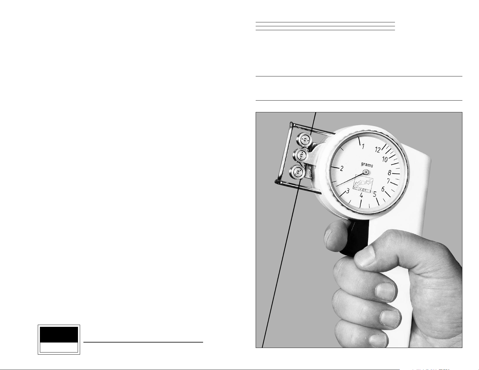
2.0 OPERATING ELEMENTS
ZF2 Models
ZD2 Models
Measured Material
Measuring Roller
Filament
Guide
Roller Guides
Trigger
Scale
Page 5

4 9
3.0 QUICK START INSTRUCTIONS
1. Prior to engaging the material under test, part the 3-roller system by pressing
and holding the Trigger.
2. Keeping the outer rollers extended, bring the instrument behind or under the
filament and move it so that the Filament Guide bars contact the process material.
3. Slowly release pressure on the Trigger until the outer rollers return to their original
position. This will automatically direct the material into the guide roller grooves.
4. The scale pointer will show line tension directly in grams or kilograms.
5. To remove the instrument from the process material, push the Trigger forward again
to open the 3-roller system. With the outer rollers extended, move the instrument
away from the material.
6. Remove the instrument and SLOWLY release pressure on the Trigger, allowing the
outer rollers to return to their original position.
CAUTION. Do not let the Trigger snap back as this may affect calibration and also
damage the instrument.
5.0 OPTIONS
5.1 High-Speed Guide Rollers
ZF2 guide roller assemblies are rated for 900 m/min., maximum. High-speed roller
assemblies are optionally available:
“K” Roller Assembly : 2,000m/min., maximum
ZD2 guide roller assemblies are rated for 2,000 m/min., maximum. High-speed roller
assemblies are optionally available:
“K” Roller Assembly : 3,500 meters/min., maximum
“HS”Assembly : 5,000 meters/min,, maximum
All high speed roller assemblies must be initially installed by the factory or an
authorized service facility.
5.2 Guide Roller Materials
ZF2 Tension Meters are supplied with hardcoated aluminum guide rollers standard.
Plastic and nickel plated steel are optionally available with a maximum rated speed
of 450 meters/min.
ZD2 Tension Meters are supplied with hardcoated aluminum guide rollers standard.
Hardened steel and ceramic are optionally available with a maximum rated
speed of 1,000 meters/min.
Page 6

8 5
4.0 CALIBRATION NOTES
The calibration process involves hanging laboratory
weights from a fixed point, engaging the vertical
line material which holds the weights with the
tension meter 3-roller system, marking a blank dial
face where the scale pointer comes to rest for each
weight used, dividing the spaces between load
“reading” marks and finish marking and numbering
to show calibration marks and “readings” on the dial
face.
The procedure requires specialized skills
and the following material:
1. A load stand to simulate the setup shown here.
2. A set of precision laboratory weights to cover the tension range of the instrument.
3. Factory “standard” nylon monofilaments as shown in the Table on page 6.
4. A Special Calibration Fixture and Metric Wrench.
A full, detailed calibration procedure is available upon request.
determination is best made by the user’s Quality Assurance Department based on the
user’s experience. However, a quick calibration check near the anticipated process tension levels should be done to confirm the integrity of the instrument, as follows:
1. At the beginning of each work session
2. Every time a unit is dropped
3. Whenever process readings seem to be out of
tolerance for no apparent reason
The quick check can be made with a simple load stand, as shown in 4.0, using a sample of the process material and weights that are close to the tensions encountered in the
process. Be sure to move the tension meter up and down slowly to simulate the motion
of the running process material. This will check the condition of the guide roller ball
bearings and remove any inertia effect of the movement. Readings that change with
this motion reversal may indicate the possibility of a guide roller ball bearing problem.
In the case of wire, which might be slightly deformed by the action of the 3-roller system during static measurement, always move to a fresh portion of the wire each time a
measurement is made. (In production, the instrument always “sees” a fresh portion.)
W
Roller
Vertical
Material
Path
Page 7

6 7
4.2 Special Calibration
Special Calibration is available when measuring on a horizontal material path with the
rollers pointing down. Please request a “down” calibration.
Special Calibration is also available for a specific material type and size so long as the
material fits the mechanical limits and range of the instrument. The customer must
supply a 10-ft sample (3 meters) of the material.
Note: Special calibration is available for a single sample only.
4.3 NIST Calibration
While all ZD2 and ZF2 instruments are furnished with a Calibration Certificate which
certifies that they have been calibrated in accordance with factory procedures and were
found to meet all published accuracy specifications, such calibrations do not fulfill
ISO-9000 requirements since no record of measured values are kept or are submitted.
Where ISO-9000 requirements are to be met, NIST calibration is optionally available
but must be specified at time of order placement or after repair.
4.4 Calibration Verification Schedule
Frequency of calibration accuracy verification depends on many factors. These include
frequency and extent of tension overloads, operating speeds, length of operating times,
environment, care in handling, etc, Such
4.1 Calibration with Factory Standard Filaments
All ZF2 and ZD2 Tension Meters are calibrated with laboratory weights suspended
from factory Standard nylon monofilament sizes, as noted in the table below. Any difference in process material size and rigidity from the Standard materials may result in
some error. For over 95% of applications, the error is not significant and can be
ignored since readings are generally treated as production setup values or are used for
comparative purposes. In those cases where highest accuracy is required, a correction
chart showing Readings vs. Actual Load should be made up by the user or “Special”
calibration should be specified when an order is placed.
Standard Calibration Monofilament Sizes
Monofilament
Model Range (g) Diam. (mm)
ZF2-5 1-5.0 0.12
ZF2-10 1-10 0.12
ZF2-12 1-12 0.12
ZF2-20 2-20 0.12
ZF2-30 3-30 0.15
ZF2-50 5-50 0.15
ZF2-100 10-100 0.15
ZD2-30 3-30 0.15
ZD2-50 5-50 0.15
ZD2-100 10-100 0.15
ZD2-150 20-150 0.15
ZD2-200 20-200 0.15
ZD2-300 20-300 0.15
 Loading...