

Page 1

– 1 –
1.0 Introduction . . . . . . . . . . . . . . . . . . . . . . . . . . . . . . . . . . . . . . . . . . . . . . . . . . . . . 02
2.0 Unpacking and Contents . . . . . . . . . . . . . . . . . . . . . . . . . . . . . . . . . . . . . . . . . 03
3.0 Setup . . . . . . . . . . . . . . . . . . . . . . . . . . . . . . . . . . . . . . . . . . . . . . . . . . . . . . . . . . . 04
4.0 AC Operation . . . . . . . . . . . . . . . . . . . . . . . . . . . . . . . . . . . . . . . . . . . . . . . . . . . . 04
5.0 Overview . . . . . . . . . . . . . . . . . . . . . . . . . . . . . . . . . . . . . . . . . . . . . . . . . . . . . . . 5
5.1 Operating Elements
5.2 Display
5.3 Operating Modes
6.0 Basic Procedures . . . . . . . . . . . . . . . . . . . . . . . . . . . . . . . . . . . . . . . . . . . . . . . 7
6.1 Changing the Pull Speed
6.2 Selecting the Baud Rate
6.3 Changing the Refresh Rate
6.4 Temperature Compensation
6.5 Cancelling the Auto-Power Off function
6.6 Changing Units of Measure
7.0 Operating Procedures . . . . . . . . . . . . . . . . . . . . . . . . . . . . . . . . . . . . . . . . . . . 10
7.1 Switching on the instrument
7.2 Resetting to Zero
7.3 Taking Measurements
8.0 Data Transfer . . . . . . . . . . . . . . . . . . . . . . . . . . . . . . . . . . . . . . . . . . . . . . . . . . . 12
8.1 RS-232C Interface
8.2 Analog Output
9.0 Calibration . . . . . . . . . . . . . . . . . . . . . . . . . . . . . . . . . . . . . . . . . . . . . . . . . . . . . 14
9.1 Changing the Pull Speed
10.0 Troubleshooting . . . . . . . . . . . . . . . . . . . . . . . . . . . . . . . . . . . . . . . . . . . . . . . . . 16
11.0 Specifications . . . . . . . . . . . . . . . . . . . . . . . . . . . . . . . . . . . . . . . . . . . . . . . . . . 17
12.0 Dimensions . . . . . . . . . . . . . . . . . . . . . . . . . . . . . . . . . . . . . . . . . . . . . . . . . . . . 18
Appendix: Pull Test Specifications for UL, MIL and SAE . . . . . . . . . . . . . . . . . 19
Warranty . . . . . . . . . . . . . . . . . . . . . . . . . . . . . . . . . . . . . . . . . . . . . . . . . . . . . . . . . . . . 20
TABLE OF CONTENTS
– 20 –
`Warranty
ELECTROMATIC Equipment Co., Inc. (ELECTROMATIC) warrants to the
original purchaser that this product is of merchantable quality and confirms in kind
and quality with the descriptions and specifications thereof. Product failure or malfunction arising out of any defect in workmanship or material in the product existing
at the time of delivery thereof which manifests itself within one year from the sale
of such product, shall be remedied by repair or replacement of such product, at
ELECTROMATIC’s option, except where unauthorized repair, disassembly, tampering,
abuse or misapplication has taken place, as determined by ELECTROMATIC. All
returns for warranty or non-warranty repairs and/or replacement must be authorized
by ELECTROMATIC, in advance, with all repacking and shipping expenses to the
address below to be borne by the purchaser.
THE FOREGOING WARRANTY IS IN LIEU OF ALL OTHER WARRANTIES,
EXPRESSED OR IMPLIED, INCLUDING BUT NOT LIMITED TO, THE WARRANTY OF MERCHANTABILITY AND FITNESS FOR ANY PARTICULAR PURPOSE OR APPLICATION. ELECTROMATIC SHALL NOT BE RESPONSIBLE
NOR LIABLE FOR ANY CONSEQUENTIAL DAMAGE, OF ANY KIND OR
NATURE, RESULTING FROM THE USE OF SUPPLIED EQUIPMENT, WHETHER
SUCH DAMAGE OCCURS OR IS DISCOVERED BEFORE, UPON OR AFTER
REPLACEMENT OR REPAIR, AND WHETHER OR NOT SUCH DAMAGE IS
CAUSED BY MANUFACTURER’S OR SUPPLIER’S NEGLIGENCE WITHIN
ONE YEAR FROM INVOICE DATE.
Some State jurisdictions or States do not allow the exclusion or limitation of
incidental or consequential damages, so the above limitation may not apply to you.
The duration of any implied warranty, including, without limitation, fitness for any
particular purpose and merchantability with respect to this product, is limited to the
duration of the foregoing warranty. Some states do not allow limitations on how long
an implied warranty lasts but, not withstanding, this warranty, in the absence of such
limitations, shall extend for one year from the date of invoice.
ELECTROMACTIC Equipment Co., Inc.
600 Oakland Ave. Cedarhurst, NY 11516—USA
Tel: 1-800-645-4330/ Tel: 516-295-4300/ Fax: 516-295-4399
Page 2
– 2 –
1.0 INTRODUCTION
Thank you for selecting the CHECK•LINE WTTM Wire Terminal Pull Tester for
your requirements. With correct use and proper care this product should provide
many years of precise and accurate testing. Please read the entire operation manual
thoroughly before using this instrument for the first time. The information contained
herein will help users to achieve accurate and repeatable results as well as prevent
damage through improper set-up or operation.
This instrument is designed for measuring tensile strength of soldered or solder-free
cable joints with end sleeves, pins, solder pins or similar wire terminal components
in the field of quality control or design validation.
Safety Precautions
Wear appropriate eye protection at all times.
The load cell can be damaged if the internal measuring system is overloaded. Do not exceed the maximum measuring limit of 50 Kg (110 lbs.,
500N) or 100 Kg (220 lb., 1000N), respectively
Transport and store the instrument with care. This reduces the risk of damage to the load cell or other minor mechanical problems which can cause
inaccurate measurement results.
Operate the instrument in appropriate environments only. The instrument
is equipped with a temperature compensation for a temperature range of
32 to 120 °F (0° to 40°C) and should be used in this temperature range
only. Do not expose this device to liquid or operate in high-humidity environments.
– 19 –
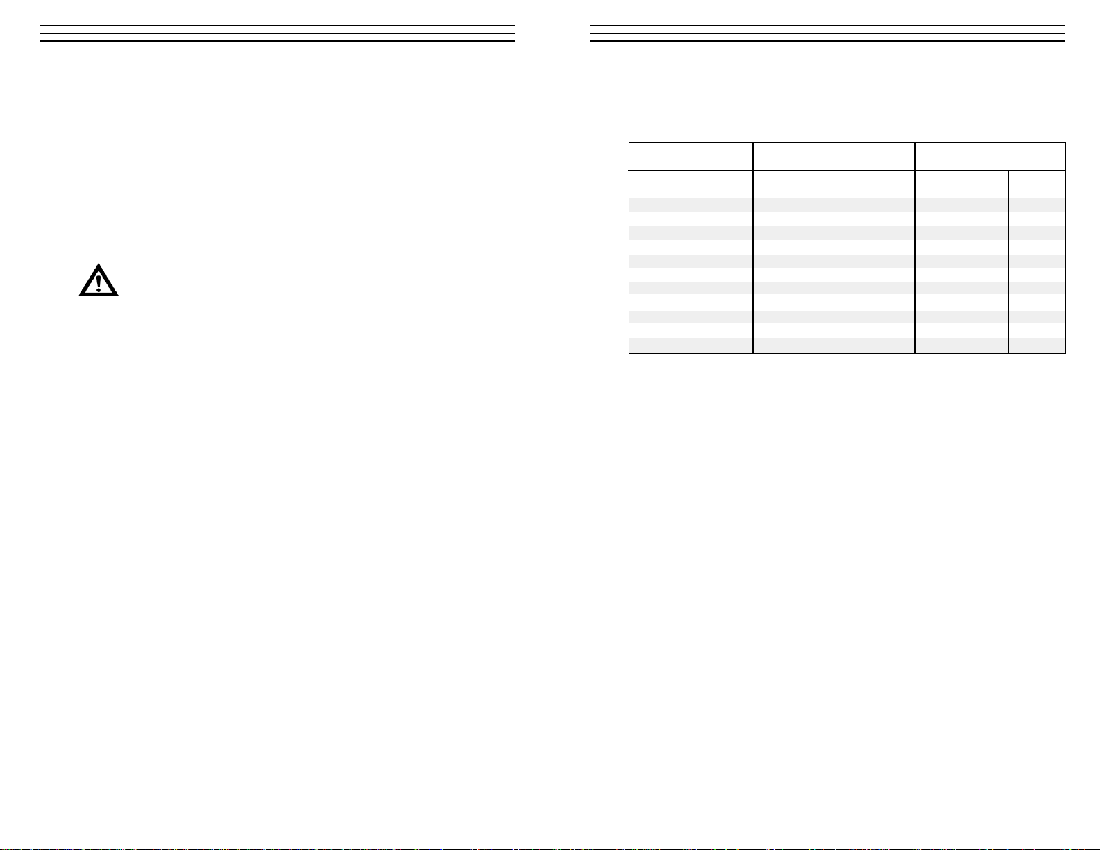
APPENDIX: PULL TEST SPECIFICATIONS FOR UL, MIL AND SAE
Size of Conductor UL 486A Table 12.1 SAE AS7928 Table II
AWG (mm2) Pounds (N) Pounds (N)
30 0.050 1–1.5 6.7 N/A N/A
28 0.080 2 8.9 N/A N/A
26 0.130 3 13.4 7 3.12
24 0.200 5 22.3 10 44.5
22 0.324 8 35.6 15 66.8
20 0.519 13 57.9 19 84.6
18 0.823 20 89.0 38 169.1
16 1.310 30 133.5 50 222.5
14 2.080 50 222.5 70 311.5
12 3.310 70 311.5 110 489.5
10 5.261 80 356.0 N/A N/A
Pull Test Specifications for UL, MIL and SAE
Page 3
– 3 –
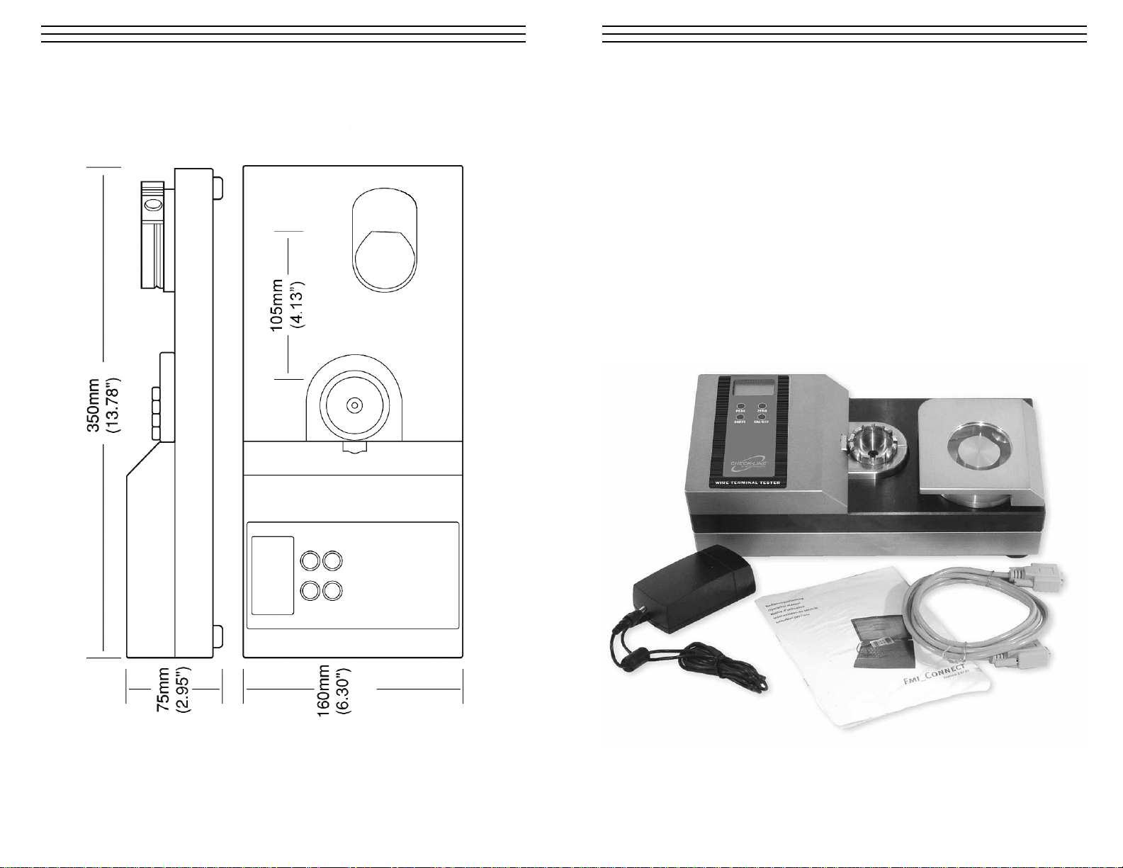
2.0 UNPACKING & CONTENTS
Remove the unit carefully and check that it appears undamaged.
Check that all of the supplied items are contained in the box (see below).
Retain packaging materials in the case that the unit needs to be returned to the
manufacturer or distributor.
■ Main instrument with integrated electronics.
■ 12 VDC power supply: 100–240 VDC (50 – 60Hz) with U. S. cord
(Part No.: 20133-US)
■ Software CD Fmi-Connect
(Part No.: FMI-972)
■ Operating instruction manual
■ Connection cable for RS232C (Part No.: 20073)
– 18 –
12.0 Dimensions
Page 4
– 4 –
3.0 SETUP
Place the WTTM Wire Terminal Tester on a level and stable work area where the user
can perform the testing in a comfortable manner. The surface should be clean and
grease-free, so that the instrument does not slip.
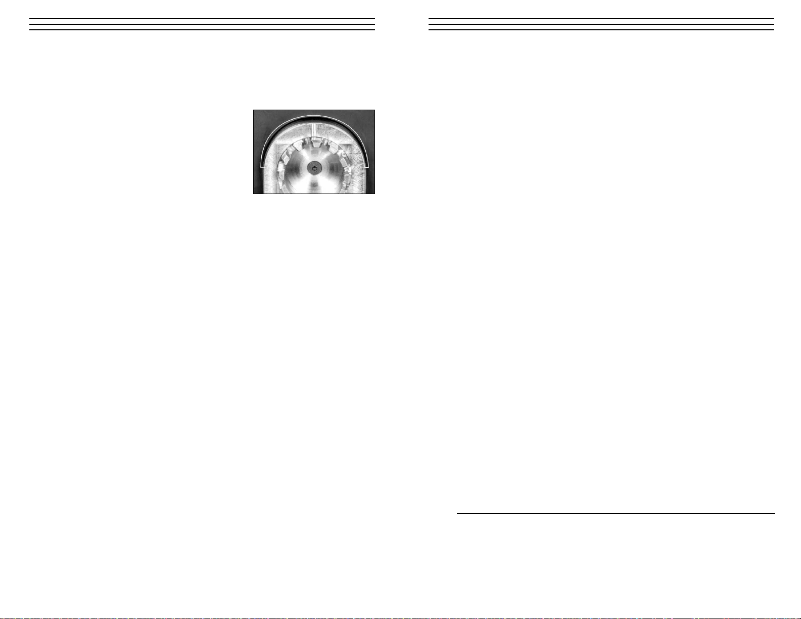
Make sure that there is no residue from the
pack-aging materials stuck under and around
any of the operating components especially in the
recessed area around the rotating terminal fixture
(see photo). Use of compressed air to clear any
debris from these areas is recommended.
Please note that the instrument weighs approximately 42 pounds (19 kg), so take care
when lifting and moving. We suggest that the instrument be located in close proximity
to an AC-Power outlet.
4.0 AC-O
PERATION
The WTTM must be operated using the AC-Adapter.
– 17 –
11.0 SPECIFICATIONS
Measuring Range* 0–50 Kg / 0–110 lbs / 0–500N or
0–100 Kg (0–220 lbs / 0–1000N)
(units selected via keypad)
Resolution 0.01Kg / 0.1 lbs / 0.1 N
Terminal adapter
slot width (mm) 0.5, 0.8, 1.0, 1.4, 1.5, 2.0, 2.5, 3.0, 3.5, 4.0, 5.0, 6.0
Accuracy ±0.5% F.S. or better
Operating Mode
Continuous Displays actual value in Kg, lbs. or N
Peak-Hold Displays peak value in Kg, lbs.or N
Wire Diameter
SAE AS7928 II AWG 8. . .30
IEC 60352-2 Cross section 0.05. . .10mm
2
Maximum 0.236" (6mm)
Overload 120%
Display LCD, 4–1/2 digit, 12mm high
Update Time (msec)
Standard 1000, 500, 333, 200, 100, 50 (selectable)
Peak 1
Memory Peak Value
Power Supply AC adapter (100-240V/50-60 Hz)
Interface (RS232C) Baud rate: 2.4, 4.8, 9.6, 19.2 Kb (selectable)
Temp. Range
Operating 32 to104 °F (0 to 40 °C)
Storage –4 to 140 °F (–20 to 60 °C)
Weight, approx. 42lbs. (19 Kg)
Dimensions 14.2" x 6.3" x 3.33" (360 x 160 x 110 mm)
Protection Code IP40
Material Anodized aluminum, steel and stainless steel
* Low-range model available on special order basis.
Page 5

– 5 –
5.0 OVERVIEW
01. ON/OFF Button Switches the instrument on/off
02. RESET Button For zero-setting after inserting the test sample
03. PEAK Button For selecting the display function, current measurement
result or peak value of the tractive force (drag indicator
function), and for calling up the peak value of the
measurement
04. MODE Button For selecting the desired measurement unit
05. Display
06. Outlet For AC Adapter
07. Outlet For data transfer
08. Terminal adapter with 12 slots for inserting the cable joint
09. Tractive force fixture for inserting the free cable end (with protection cap)
10. Selector switch for pull speed (access protected by screw connection)
5.1 Operating elements
– 16 –
10.0 TROUBLESHOOTING
No indication on display Plug in the AC-adapter and check the electrical
connections.
RS-232C communication Check the wiring of the connection cable and the
is disturbed compliance of wiring within the input terminals
of the PC-card.
Error Code Indications:
OV+ Overload of +120%. Reduce the load until the
instrument indicates a value within the admissible
measuring range.
OV- Overload of –120%. Reduce the load until the
instrument indicates a value within the admissible
measuring range.
OVP Overload +!! The load cell can be damaged. Remove the
excessive load immediately and check the instrument. If
the indicated measuring values are obviously incorrect,
the load cell must be replaced by the manufacturer.
OVM Overload -!! The load cell can be damaged. Remove the
excessive load immediately and check the instrument. If
the indicated measuring values are obviously incorrect,
the load cell must be replaced by the manufacturer.
ERR –3- Reading error of the E_proms. Switch off the instrument
and turn it on again. Should the error still exist, the
microprocessor may need to be replaced by the
manufacturer.
ERR –4- Reading error of the E_proms. Switch off the instrument
and turn it on again. Should the error still exist, the
microprocessor may need to be replaced by the
manufacturer.
Pull force fixture Remove the AC-adapter/charger, close the protection
does not work cover and wait for approx. 5 minutes. Plug in the
AC-adapter again and switch on the instrument. If the
display does not show any of the error codes above and
still does not work, please send the instrument back for
inspection to your dealer or directly to the
manufacturer.
Page 6

– 6 –
LL00--BBAATT
PPEEAAKK
LLbb
ff
00..00 0000
1
3
4
2
– 15 –
Recalibration Procedure
For recalibration, you would need a solid and vibration-free rack and a test weight
(50kg or 100kg), preferably Class M1, which complies with the international
standard.
Before calibrating the load cells, the pull force fixture must be brought back to the
zero-position. In order to do this, adjust the selector switch for the pull speed to “0”
and switch on the instrument.
1. Switch off the instrument using ON/OFF button.
2. Press and hold MODE, PEAK and RESET buttons simultaneously.
3. While keeping the above buttons pressed, press the ON/OFF button until CAL is
indicated in the display and the calibration weight code (??) is shown. Then
release all buttons. The WTTM is now in calibration mode
4. Press the MODE button. The signs SNC and –00– flash for approx. 10 seconds
followed by the indication ZER 88888.
5. To confirm the calibration of the zero point press the RESET button. The
indication SCN 88888 flashes on the display for approx. 15 seconds, followed by
PEK 88888. The first step of the calibration is now complete.
6. Hang the calibration weight on the terminal adapter. When the weight hangs
perpendicular and still, you may save the full-scale value.
7. Press the PEAK button. The display flashes for approx. 15 sec. with the sign
SCN 88888 followed by the sign END 88888. After a further period of approx.
5 sec., the sign OK 88888 indicates that the calibration was successful. The
instrument switches off automatically.
8. Should the calibration fail, the display will show ERR 88888 instead. The original
calibration datas are still saved in the memory. You may remove the weight and
repeat the recalibration procedure
CAL
–00–
“oK”
88888
“SCN”
–00–
ZER
88888
➔
“SCN”
88888
PEK
88888
➔
“SCN”
88888
“End”
88888
➔➔
1 Low Battery Indicator. Flashes when batteries need charging, turns off
when fully charged. Remains on while charging.
2 Peak Mode Indicator. Shown on display when configured for peak mode
(stores highest peak force until it is reset by pressing zero key)
3 Units Indicator. Displays currently selected units of measure (pounds,
newtons or kilograms). Changed by pressing UNITS key.
4 Force Value. Displays current or peak force value in user-selected units of
measure.
5.3 Operating modes
The WTTM can be set to operate in one of two distinct operating modes: Peak
Capture or Average. In Peak Capture Mode, the system measures the force at a
frequency of 1000 Hz (1000 times per second) and displays the highest force
measurement. The peak value remains on the display until a higher force value
is measured or until the user presses the ZERO key.
In Average Measurement Mode, the system measures the force at a frequency
of 1000 Hz (1000 times per second) and displays the average each time the display is updated. The factory default display update rate is 3 times per second (1
time every
1/3 second).
Note: Refer to section 7.3, page 8, for additional information and to change the
update rate.
5.2 Display
Page 7

– 7 –
6.0 BASIC PROCEDURES
6.1 Changing the pull speed (default: 50mm/min)
The pull speed can be adjusted
according to the testing standards.
You need a small and a large screw
driver to do this. The selector switch
is protected by a screw thread cap,
in order to avoid an unintentional
manipulation of the pull speed.
To adjust the pull speed:
1. Switch off the instrument and
unplug the power supply.
2. Loosen the protection cap with
the large screw driver (flat or phillips head?).
3. Adjust the selector switch to the desired pull speed (How? Using the small
screw driver?)
4. Replace and tighten the protective cap.
Standard Speed Switch Position
DIN IEC 60352 Part 2* 25 mm/min 1
UL 486 C
DIN IEC 60352 Part 2
UL 486 C 37.5 mm/min 2
DIN IEC 60352 Part 2 50 mm/min
UL 486 C
SAE AS7928 Table II 3
SAE AS7928 Table II** 100 mm/min 4
SAE/USCAR-21
SAE/USCAR-21 150 mm/min 5
SAE/USCAR-21 200 mm/min 6
SAE/USCAR-21 250 mm/min 7
* DIN IEC 60352 Part 2 replaces DIN 4161/3 ** SAE AS7928 Table II replaces MIL-T-7928
BS5B178 corresponds to IEC 60352 Part 2 UL486A corresponds to IEC 60352 Part 2
– 14 –
10.0 CALIBRATION
The WTTM Pull Tester has been calibrated in accordance with factory procedures and
is certified to perform within the stated accuracy specifications shown in the
Specifications section found on page 18. Assuming the unit is handled with care
and operated as detailed in this manual it should remain accurate for an extended
time period. If however, it is subjected to forces that exceed its maximum range or
if it is not properly cared for, it might need to be recalibrated.
It is recommended that the calibration is verified at least on an annual basis and more
frequently if feasible. Normally, instruments of this type go out of tolerance from one
day to the next and rarely on a regular periodic basis.
A calibration procedure is provided in this manual, however it should only be performed by individuals properly trained for this type of service and with the appropriate
certified standards (known weights or secondary force measuring system such as a
load cell, etc.).
Re-Calibration Set-up
1. Remove the lever by unscrewing it in a
counter-clockwise direction and move
the Wire Clamp assembly out from the
path of the hanging sample.
2. Position the WTTM in a vertical
position so that the keypad & display
are at the top (refer to photo). Be sure
to secure it so it can not topple over
when the weight is attached.
3. Using a heavy-duty monofilament
(fishing line), wire or similar, suspend
a 50 Kg weight from one of the teeth
on the wire terminal fixture by hooking
a loop of the material over the selected
tooth.
4. Temporarily, remove the weight and
follow the Re-Calibration Procedures
shown on page 16.
■ Make sure that the
WTTM is well secured
in the vertical position.
Caution
■ Select a material that is strong
enough to support 50 Kg of weight.
need photo
Page 8

– 8 –
6.2. Selecting the baud rate of the RS232C interface (Default: 19200)
The speed of the data transfer for the RS232C interface can be adjusted to match
your data acquisition rate by changing the baud rate as follows:. This is possible
by changing the baud rate:
1. Switch off the instrument.
2. Press and hold RESET button.
3. Press the ON/OFF button.
4. Wait until f01 is displayed, then release RESET button.
5. Select function f04 by repeating to press the PEAK button until f04 is shown
on the display.
6. Press the MODE button repeatedly until the appropriate baud rate
(2400 / 4800 / 9600 / 19200) shows on the display.
7. Press the RESET button to save your settings.
6.3. Changing the up-date (refresh) rate of the display (Default: 3/sec)
The force applied to the load cell of the instrument is internally processed at a
rate of 1000Hz, which allows the precise capturing of the peak values. The readings on the display, however, are refreshed at a default rate of 3 times/sec. You
may increase or decrease the factory settings to match your personal demands as
follows:
1. Switch off the instrument.
2. Press and hold the RESET button.
3. Press the ON/OFF button.
4. Wait until f01 is displayed, then release the RESET button.
5. Select function f02 by repeatedly pressing the PEAK button until f02 is
shown on the display.
6. Press the MODE button repeatedly until the desired refresh rate
(1 / 2 / 3 / 5 / 10 / 20 times/sec) appears on the display
7. Press the RESET button to save your settings.
6.4 Temperature Compensation (default: SET = on)
In general, it is recommended to have the this function turned on as long as it
does not effect your measuring results. Only when measuring very minute
forces over a longer period of time at a slow rate and under stable environmental
conditions might it be useful to switch this off.
1. Switch off the instrument.
2. Press and hold PEAK and MODE buttons.
3. Press ON/OFF button.
4. Wait until TRK oFF is displayed.
5. Release PEAK and MODE buttons.
TRK
oFF
– 13 –
8.2 Analog Output
The analog output (-1...0...1 VDC) can be used for any data acquisition or data
recording device. Pull Force data will be expressed as a negative voltage. The
signal can be set to zero (reset) by performing a ZERO (tare) function. +1 VDC
and – 1VDC refers to the maximum and minimum full scale (end of nominal
measuring range).
PROTOCOL CODE
Extern >> Average data output NA®®®®®®cr
3. digit: + /or –
4.-6. digit. Value incl. floating decimal point
Peak data output NB®®®®®®cr
3. digit: + /or –
4.-6. digit. Value incl. floating decimal point
Unit: 3 digit
0 = N
1 = kg (g)
3= lb (oz) NH®cr
Unit: 3 digit NH®cr
0 = N
1 = kg (g)
3= lb (oz)
Error OBcr Command Error
OEcr Parity Error
OFcr Format Error
OGcr Summing Error
OHcr Overflow
SPECIFICATION
Amplitude -1VDC / +1VDC
Signal generator 12-bit D/A-Converter
Signal update 100 Hz
Page 9

– 9 –
6.6 Changing Units of Measurement
The WTTM can display force measurements in any of the following three engineering units:
■ lbf (pounds)
■ N (Newtons)
■ Kgf (kilograms)
To change the selected engineering units for display press UNITS key. Each
time the key is pressed, the units will change from one to the other as follows:
Lbf
Kgf
N
– 12 –
SPECIFICATION
Baud rate 2400, 4800; 9600 or 19200 (selectable, see general settings)
Data length 8 bits
Stop bit 1
Parity None
PROTOCOL CODE
Extern >> AAcr Tare
ABcr Stop Output
ACcr Change to Peak Mode
ADcr Change to Average Mode
AEcr Reset Peak
AFcr Change Units to kg (g)
AGcr Change Units to N
AHcr Change Units to lb (oz)
BAcr Data output request (single reading)
BBcr Data output request (10/sec)
BB1cr Data output request (20/sec)
BB2cr Data output request (50/sec)
BB3cr Data output request (100/sec)
BDcr Units confirmation request
BEcr Peak data output request
BFcr Minus peak data output request
cr (carriage return)
Chart continues on next page
8.0 DATA TRANSFER
Model WTTM testers can transfer measuring data by means of an RS-232C interface.
A 9-pin D-Sub connector is provided for this purpose, which can be found at the left
side of the instrument. A connector cable for the serial port is included. If a custom
serial cable must be used or if the user wishes to access the analog output, the pin
designations are as follows:
8.1 RS-232C Interface
The RS-232C interface can be used for the direct communication between an
appropriate serial I/O-card of a computer and the instrument. The minimum
requirement for the data transfer up to 19200 baud is the connection of the
RXD, TXD and GND communication terminal.
SPECIFICATION
Baud rate 2400, 4800; 9600 or 19200 (selectable, see general settings)
Data length 8 bits
Stop bit 1
Parity None
PROTOCOL CODE
Extern >> AAcr Tare
ABcr Stop Output
ACcr Change to Peak Mode
ADcr Change to Average Mode
AEcr Reset Peak
AFcr Change Units to kg (g)
AGcr Change Units to N
AHcr Change Units to lb (oz)
BAcr Data output request (single reading)
BBcr Data output request (10/sec)
BB1cr Data output request (20/sec)
BB2cr Data output request (50/sec)
BB3cr Data output request (100/sec)
BDcr Units confirmation request
BEcr Peak data output request
BFcr Minus peak data output request
cr (carriage return)
Pin Description
1 0...1 VDC (analog out)
2 Serial : TXD (RS-232C)
3 Serial : RXD (RS-232C)
5 Serial : CD (RS-232C)
9 Analog: Gnd (analog out)
Page 10

– 10 –
7.0 OPERATING PROCEDURES
7.1. Switching on the instrument, selecting the measurement unit and
operational mode
1. Switch on the instrument by pressing the ON/OFF button.
After a power-up self test and calibration (approx. 20 sec.), the display will
indicate the last selected measuring unit, function and the value 0.00.
2. Select the desired operation mode (indication of the current measurement
value or the peak value) and the measuring unit by pressing the PEAK and
MODE buttons simultaneously. The current settings will be indicated on the
display. When you choose the PEAK mode, the peak value will be always
indicated on the display (drag indicator function).
7.2. Resetting to zero before each measurement
It is necessary to zero-set the instrument before starting
each pull force measurement. Press the RESET button
for this purpose. The RESET button can also be used
for deleting the peak value updated in the memory.
7.3 T aking Measurements
NOTE: Select the smallest suitable slot for the test
sample diameter.
1. Place the cable connection into the adapter, so
that the sleeve of the cable connector stays
securely inside the ring and cannot be pulled out
through the slot.
2. Insert the free cable end with slight tension into
the clamping fixture. The nut in the pull force
fixture will help you to find the right position
for the cable.
3. Holding the cable tight and securely, close the
protection cover.
N
0.0
– 11 –
4. The motor starts and closes the pull force
fixture. Hold the cable end securely until the
pull force develops.
5. The rotational motion of the pull force fixture
tears off the cable from the terminal joint. The
motor stops when the maximal pull length has
been reached.
6. When you open the protection cover, the pull
force fixture returns back to the original
position and releases the cable.
7. During the measurement, the force progression
can be read off the display.
The peak value, which mostly appears before the
connection breaks, is captured at 1000Hz and is
indicated when the PEAK button is pressed (so
long as the drag indicator function was not active).
Depending on the wire strength and the related standard, the following
tensile strength should at least be achieved.
AWG Cross-Section Cable Diameter SAE AS7928 IEC 60352 Part2 UL 486 C
Table II
30 0.06 mm_ 0.36 mm 6 N 6 N
28 0.09 mm_ 0.38 mm 11 N 11 N
26 0.14 mm_ 0.48 mm 32 N 18 N 18 N
24 0.22 mm_ 0.61 mm 45 N 28 N 28 N
22 0.34 mm_ 0.76 mm 67 N 40 N 40 N
20 0.56 mm_ 0.97 mm 85 N 60 N 45 N
18 0.93 mm_ 1.27 mm 170 N 90 N 45 N
16 1.25 mm_ 1.44 mm 223 N 135 N 68 N
14 1.93 mm_ 1.80 mm 312 N 200 N 100 N
12 3.16 mm_ 2,29 mm 490 N 275 N 138 N
10 4.65 mm_ 3.10 mm 355 N
* DIN IEC 60352 Part 2 replaces DIN 4161/3 ** SAE AS7928 Table II replaces MIL-T-7928
BS5B178 corresponds to IEC 60352 Part 2 UL486A corresponds to IEC 60352 Part 2
Page 11

ELECTROMATIC
E Q U I P M E N T C O., I N C.
600 Oakland Ave., Cedarhurst, NY 11516–U.S.A.
TEL: 516-295-4300
• FAX: 516-295-4399
CHECK•LINE
®
INSTRUMENTS
WTTM
W
IRE TERMINAL PULL TESTER
Operating Instructions
CHECK•LINE
®
BY ELECTROMATIC
XXXXX
 Loading...