

Page 1
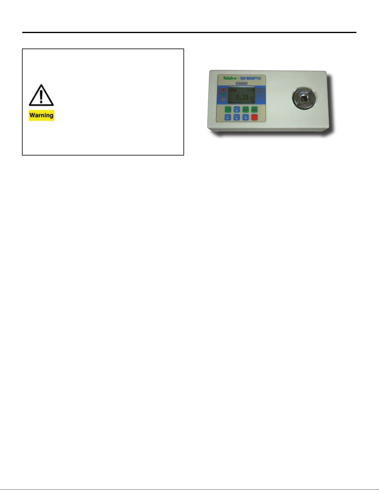
TT Torque Tool Tester
Operation Manual
1) Overloading the transducer does not only damage the transducer but
may break the transducer head and could result in injury!
2) Torque ranges of 25 N-m and higher must be fastened properly with 4
bolts and nuts to a secure work surface, either horizontally or vertically.
Failing to do so may result in damage to the transducer and could result
in injury to the operator. Ranges 10 N-m and lower do not require mounting and may be used with the included rubber feat as long as precaution
is taken and unit is secured to prevent slippage.
3) Ensure that the torque wrench’s driver has engaged the transducer
socket properly when operating. The transducer head may be damaged
if not engaged properly and could result in injury to the operator.
4) Please make sure that you have safety gear and safety precautions
in place when applying torque to the transducer or when calibrating
the transducer.
5) Do not use a charger other than the unit supplied with the TT torque
tester. Using the incorrect charger may result in damage to the Ni-MH
rechargeable batteries.
NIDEC-SHIMPO INSTRUMENTS
The TT Digital Torque Tool Tester is a simple operation test instrument for quickly checking torque tool performance. The TT Series
provides exceptional accuracy for measuring torque on various
products including torque wrenches, manual screwdrivers, electric screwdrivers, pneumatic screwdrivers and other torque controlled power tools.
The TT’s provide long operation life and power flexibility with the
ability to work from the internal rechargeable battery or included
AC adapter. The TT’s have four modes of operation: Track for live
readings, Peak which records the highest level over a test, First
Peak which records the first peak reading over the test and Track/
Peak which shows both the live readings as well as the peak reading recorded.
The backlit display provides an analog bar graph on screen to
allow the user to know where the resultant torque is currently positioned compared to the full scale range of the unit. CW/CCW
icons along with programmable pass/fail LED’s ( HI/OK/LO) assist
users with ensuring proper test set up along with enabling a quick
determination of the results.
Every tester comes standard with USB and RS-232 output. The
TT’s software enables the uploading of data and the additional
statistical analysis with its auto-calculation of the selected values.
These excellent features make the TT Torque Tool Testers a valuable and versatile addition to the production and quality control
departments.
SPECIFICATIONS
Accuracy: ± 0.5 % of full-scale.(Includes Creep, Non-linearity &
Temperature Shift at zero load)
Units of Measure: N-mm, N-cm, N-m, in-lb, ft-lb, kg-cm, kg-m
(depending on range)
Measure Modes: Track, Peak, First-Peak, Track/Peak
Tool Socket Size: Dual 3/8”, 20 mm female square.
Overload Protection: 120% of Full Scale
Max. Mounting Torque: 150% of Full Scale
Sampling Rate: 1000 Hz
Peak Capture Rate: 0.10 S
Display: 175 x 1.125˝ (44.4 x 28.6 mm) dot matrix backlit LCD
Operating Temperature: 60 - 95 ºF (15 to 35 ºC)
Storage Temperature: 5 - 149 ºF (-15 to 65 °C)
Humidity Limit: Maximum 70% rH.
Power Requirement: 500 mA 9 VDC
Charging Time: Approx. 14-16 Hours for Full Charge
Battery Operation: 12 Hours
Output: USB 8 data bits Baud rate: 38400
Communication Ports: Both RS232 & USB simultaneous output
Size: 4 x 8 x 2” (100 x 200 x 50 mm);
TT-25: 4 x 9.8 x 2.3” (100 x 250 x 58 mm)
Product Weight: 2.4 lb (0.9 kg); TT-25: 4.9 lb (2.22 kg)
Package Weight: 5.1 lb (2.3 kg); TT-25: 7.7 lb (3.49 kg)
Warranty: 1 year
Included Accessories: USB cable, charger adapter, cal. cert.,
3/8” Hex rundown adapter (1, 5 & 10 N-m ranges only).
Optional Accessories: RS-232 cable, Rundown adapter
springs, Rundown adapters. Note: Software available for free
download at www.shimpoinst.com.
Page 2
INTRODUCTION
Thank you for selecting the Nided-Shimpo TT series torque tool
tester. With correct use and regular re-calibration, the TT tool tester will provide many years of accurate and reliable service.
The Series TT can accurately measure torque in both the ClockWise (CW) and Counter Clock-Wise (CCW) direction. The TT provides simple user operation and is accompanied with software
and accessories to simplify your torque testing needs.
Before Use
Upon receiving the unit, please check that no physical damage
has occurred to the packaging, plastic carrying case or the instrument itself. If any damage is evident, please notify Nidec-Shimpo
immediately.
Operation Overview
The most commonly used features, such as displaying torque,
peak hold, zeroing and changing of displayed units, can all be
done by pressing a single dedicated key identified on the front
panel. See the Basic Functions section. To access the menus,
simply press the Menu key to access the tester configurations.
See the Main Menu section.
POWERING THE FIRST TIME
The TT is supplied with a set of Nickel Metal Hydride 4xAAA rechargeable batteries. For safety reasons during transportation the
batteries are shipped discharged. To obtain maximum battery life
we recommend that you charge them with the supplied charger/
adaptor for at least 14-16 hours when you first receive the instrument.
Battery Indicator
If battery level shows empty, a “ battery empty” message will be
displayed and the tester will power down automatically.
Important: Only use the adaptor/charger supplied.
USING THE TT
Fitting Accessories
If power torque tools are used, the rundown adapter provided can
be inserted to the torque transducer head. For wrench and torque
screwdrivers, you may need a matching adapter.
Power Up
To power up the tester press the ON/OFF key. A short self-test
runs during which the display will show the capacity in Newtons.
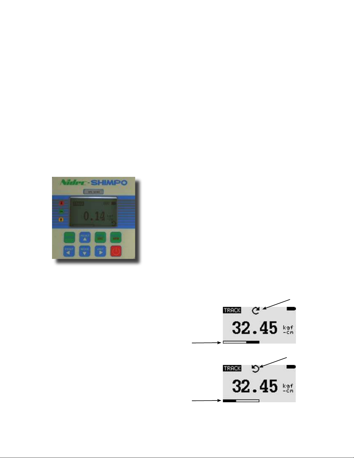
Figure 1: TT Keypad
ZERO:
Resets the displayed value to zero
POWER: Turns unit on/off
UNIT: Home screen changes engineering units.
In Menus, moves cursor to the right position
MODE: Home screen, scrolls through 4 modes of
operation. In menus, moves cursor down in the list or
decreases a value
RESET: Home screen, resets the maximum
values. In menus, moves cursor up in the menu list or
increases a value
The TT re-zeroes itself during the self-test routine.
After the self-test, providing no load has been applied to the instrument, the display will show all zeroes.
*
Do not overload
the load sensor. This will cause irreparable
damage. Torques greater than 120% of full-scale will produce an
audible beep and OL symbol will blink on the display until the load
is released and the RESET key is pressed.
To power down the tester press the ON/OFF key.
*All the current settings are saved when the tester is turned off. The
tester will function in the same mode when powered up again.
Basic Functions
Clock-Wise(CW) torque is displayed by the right pointing arrow
symbol (see image below). Counter Clock-Wise torque is displayed by the left pointing arrow symbol (see image below).
Clockwise
Symbol
Load Indicator
Bar for
Clockwise
Counter-Clockwise
Symbol
ENTER/MEM: Home screen, enters data into memory
storage In menus, enters into sub-menus, makes
selections and enters values.
MENU/ESC: Home screen, enters into menus
In menus and sub-menus, returns one level
PRINT: Home screen, sends current reading to PC
In Menus, moves cursor to the left position
2
Load Indicator
Bar for
Counter-
Clockwise
Figure 2: Display of Clockwise & Counter-Clockwise
Page 3

A load indicator bar alerts the operator how much load has been
applied to the load sensor in relation to the full scale of the sensor.
For clockwise torque the indicator bar moves from right to left.
For counter-clockwise torque the indicator bar moves from left to
right.
Zeroing the Tester
During operation of the TT, it is often necessary to zero the display
so that minor errors do not become part of the measured reading.
Press and release the ZERO key.
Changing the Engineering Units
Depending on the capacity of your model, the following units
may be selected by pressing the UNITS key: N-mm, N-cm, N-m,
gmf-cm, kgf-cm, kg-m, ft-lbf, in-lbf. The TT automatically converts
readings as the new engineering unit is selected.
Changing the Mode
Press the Mode key to choose from the following modes of measure: Track, Peak, First Peak and Track/Peak
Track Mode
When “Track” appears in the display the TT will indicate live torque
readings in both directions as they are applied. See Figure 3a
Peak Mode
When “Peak” is selected the TT will show the maximum torque
recorded over the test. Subsequent increases in the peak will replace the existing peak value shown. See Figure 3c
Peak Torque
Symbol
Figure 3c: Peak
Peak/Track Mode
There are two readings on the screen at once. Upper area displays the peak torque. The larger, main value shows the live
torque reading.
- Press “Mem” button: Only peak torque will be stored in the
tester’s memory.
- Press “Print” only: The peak torque will be sent to PC
Track
Symbol
Figure 3a: Track
First Peak Mode
When “F-Peak” is selected the TT will show the initial maximum
torque recorded over the test. Once the unit sees a drop in torque,
the First Peak will be displayed. A subsequent increase after the
drop will not be recorded. See Figure 3b
First Peak
Torque Symbol
Figure 3b: F-Peak Torque
Peak & Value
Figure 3d: Peak Torque
Resetting the Tester
Press the RESET key to clear maximum readings.
Backlit Display
When you press any key, or apply torque to the load sensor greater than 0.5 % of full scale the backlight will come on and remain
for 60 seconds.
Saving Readings to Memory
A reading can be saved at any time by pressing ENTER/MEM key.
A total of 500 readings may be stored in the database.
Figure 3e: Number of values saved in Memory
3
Page 4

Computer Communication
A computer can communicate with the TT through either the RS232 or USB connections. See commands and actions below.
1) SETUP
1) AUTO-OFF
2) PASS-FAIL
Command Action
“m” Change the measure mode.
“u” Change the engineering unit.
“z” Zero the tester.
“r” Reset the tester.
Output Signal
The displayed reading may be transmitted to a PC by pressing the
PRINT key or sending a request command from the PC to the TT
via USB or RS-232 ports.
Command Action
“l” Send live reading value with unit.
“p” Send peak Torque value with unit.
“c” Send peak Torque value with unit.
“x” or pressing
PRINT key
“d” Send memory
“!” Send information of tester (model,
Send live reading value with unit, if current
mode is track mode.
Send peak Torque value with unit, if current
mode is peak Torque mode.
Send peak Torque value with unit, if current
mode is peak Torque mode.
capacity, serial number, firmware revision,
original offset, current offset, overload count).
MAIN MENU
Press MENU/ESC key to access the main menu. To move between the sub-menus listed, press the UP and DOWN arrow keys
to move the cursor. Press ENTER to select the sub-menus, activate features and enter values. Within the sub-menus the UP,
DOWN, LEFT and RIGHT arrow keys will also change numerical
values. Press ESC to return to the main menu page.
MAIN MENU
1) SETUP
2) MEMORY
3) CALIBRATION
4) DIAGNOSTIC
5) ABOUT
a) AUTO-OFF: With AUTO-OFF highlighted, press the ENTER
key. The display will show the Auto-OFF options. See Figure 5.
Press the ESC key to return to the main menu page.
The Auto-OFF feature can be enabled to conserve battery life
where the TT powers down after inactivity of 5, 10 or 15 minutes.
Press ENTER to select the desired option and return to the main
menu page. The power symbol “O” will appear on the home
screen when this feature is active.
AUTO-OFF MENU
1) OFF
2) 5 MINUTE
3) 10 MINUTE
4) 15 MINUTE
Figure 5: Auto-Off Menu
b) PASS-FAIL
With PASS-FAIL highlighted, press ENTER. The Pass-Fail feature is used to set an acceptable maximum and minimum torque
zone for testing. It activates by setting the lower level and upper
level torque limits. If the torque value is within the thresholds, the
display will show PASS. Any values outside this zone (higher or
lower), will display FAIL. If you activate this feature, a PF symbol
will display at the home screen.
Alter Units at bottom
Use the LEFT ARROW key to move between the values. Use the
UP and DOWN keys to change the values. Press and hold to
adjust the values more quickly. Use the RIGHT ARROW key to
change the units. Press ENTER to save the settings and return to
main menu page.
PASS FAIL MENU
UPPER= 2.5
LOWER= 1.0
Unit=in-lbf
ZERO key to reset
Figure 6: Pass-Fail Menu
*Either UPPER or LOWER Levels can be disabled if you set to 0.
*If UPPER is active, LOWER value must be less than the UPPER.
Figure 4: Main Menu
4
Page 5

Example: LOWER LEVEL = 0 N.m, UPPER LEVEL = 20 N.m
Load
“UPPER” LED on
Upper Level
“OK” LED on
Time
Figure 6a
Example: LOWER LEVEL = 20 N.m, UPPER LEVEL = 0 N.m
Load
“OK” LED on
Lower Level
3) CALIBRATION: The calibration feature is used by service technicians for calibrating the tester. Proper equipment is required to
perform this task. Contact Nidec-Shimpo or your dealer for additional details.
4) DIAGNOSTIC: This diagnostic feature is used to check status
of the load cell. If you suspect that your load cell transducer has
sustained an overload, it is possible to check the status. Place the
tester horizontally on the flat level surface and select “DIAGNOSTIC” in the main menu.
DIAGNOSTIC
OVERLOAD COUNT: 2
ORG. OFFSET: +0.4%
CUR. OFFSET: +0.4%
A total of overload count
% offset from the
prior calibration
Current % offset
Figure 8: Diagnostic Menu
“LOWER” LED on
Time
Figure 6b
Example: LOWER LEVEL = 10 N.m, UPPER LEVEL = 20 N.m
Load
“UPPER” LED on
Upper Level
Lower Level
“OK” LED on
“LOWER” LED on
Time
Figure 6c
2) MEMORY: The TT offers the ability to view saved records, de-
lete last or delete all records. It can also upload the data if connected to a PC. To access, in the menu list highlight Memory and
press ENTER.
MEMORY MENU
1) VIEW
2) DELETE LAST
3) DELETE ALL
4) UPLOAD ALL
Figure 7: Memory Menu
In the VIEW sub-menu, Press UP and DOWN to scroll through the
list of values. Press and hold to scroll through more quickly.
Select 2) Delete Last and press ENTER. Choose Yes and the
tester will delete the last saved record and return to the Memory
menu. If you selected 3) Delete All and press ENTER, choose Yes
to remove all stored records. The unit will automatically return to
the memory menu after the selection.
If the % offset is between 5% - 10 % please contact Nidec-Shimpo
or your supplier to arrange for a proper calibration.
If the % offset is greater than 10% the unit is possibly damaged
and needs repair or replacement.
These values are given as an indication only. The need for calibration or repair may vary according to the individual characteristics
of the load cell.
5) ABOUT: The ABOUT sub-menu displays the information of
your unit such as Firmware revision, Model, Capacity and Serial
number.
ABOUT
FIRMWARE REV.: 1.00
MODEL: TT
CAPACITY: 10 N.M
S/N: 05130001
Figure 9: About Menu
MOUNTING: For proper operation and safety, it is necessary to
mount the torque tester with ranges of 25 N-m and higher. Fasten
the integral mounting bracket properly with 4 bolts and nuts to a
secure work surface. Mounting may be vertical or horizontal. For
lower torque ranges, this mounting bracket adapter is available
as an accessory if securing to a work surface is desired. To install
the bracket to the back of the unit, remove the four outer screws
with rubber feet. Disguard the rubber feet. Line up the adapter
plate’s four holes with the four outer threaded inserts on the bottom of the TT. Attach the adapter bracket with the four screws that
were previously removed. Tighten securely. Line up the adapter
plate’s four holes with the four outer threaded inserts on the bottom of the TT.
To upload all the values to the PC software program, highlight
UPLOAD ALL and press the ENTER key.
5
Page 6

CAPACITY & RESOLUTION
Range by unit (Resolution)
Model N-mm N-cm N-m kgf-cm kgf-m in-lbf ft-lbf
TT-0.5 500 (0.1) 50 (0.01) 0.5 (0.0001) 5.099 (0.001) 0.0509 (0.0001) 4.425 (0.001) 0.3687 (0.0001)
TT-1 1000 (0.2) 100 (0.02) 1 (0.0002) 10.2 (0.002) 0.1020 (0.0001) 8.850 (0.002) 0.7375 (0.0002)
TT-5 5000 (1) 500 (0.1) 5 (0.001) 50.99 (0.01) 0.5099 (0.0001) 44.25 (0.01) 3.687 (0.001)
TT-10 10000 (2) 1000 (0.2) 10 (0.002) 102 (0.02) 1.02 (0.0002) 88.50 (0.02) 7.375 (0.002)
TT-25 25000 (5) 2500 (0.5) 25 (0.005) 254.9 (0.05) 2.549 (0.0005) 221.3 (0.05) 18.44 (0.005)
TT-100 - 10000 (2) 100 (0.02) 1019.7 ( 0.2) 10.197 ( 0.002) 885.07 ( 0.2) 73.75 ( 0.02)
TT-200 - 20000 (5) 200 (0.05) 2039.4 ( 0.5) 20.394 ( 0.005) 1770.15 ( 0.5) 147.5 ( 0.05)
Optional Mounting Bracket
Comes Standard with TT-25
 Loading...