

Page 1

Force Test Stands Series TS
MODELS TSA750, TSA750H,
TSB100, TSC1000 & TSC1000H
User’s Guide
Page 2

Series TS Force Measurement Test Stands
Thanks!
Thank you for purchasing a Mark-10 Series TS Force Measurement
Test Stand. We are confident that you will get many years of service
from this product.
Series TS Force Measurement Test Stands can be used in any number
of compression and tension testing applications. To maintain smooth
mechanical functioning of your test stand, avoid repetitive overloads
and shock loads.
We hope that this User’s Guide will provide a comprehensive explanation of the test stand’s operation and sufficient detail on its specifications. However, if you have any questions or concerns our technical
support and engineering teams will be eager to help you.
Thank you again for your purchase and happy testing!
TABLE OF CONTENTS
UNPACKING AND SETTING UP ............................................... 3
LIST OF INCLUDED ITEMS ....................................................... 3
OPERATION, SPECIFICATIONS, AND DIMENSIONS ............. 4
TSA750 / TSA750H ........................................................................ 4
TSB100 .......................................................................................... 6
TSC1000 / TSC1000H.................................................................... 8
WARRANTY ............................................................................. 10
Page 3
User’s Guide
UNP ACKING AND SETTING-UP
1. Carefully unpack the stand and inspect for any damage. Check to make
sure that you have received a complete test stand with all accessories – see
the “List of included items” section below.
2. Install the loading lever on Models TSA750, TSA750H and TSB100. The
position of the loading lever can be adjusted as required – see the
“Operation” section for your particular model. No assembly is required for
Models TSC1000 and TSC1000H.
3. Place the stand on a firm, flat and level working surface free from vibration
to ensure accurate readings. It is recommended that the test stand be secured to a work bench – see the “Operation” section for your particular
model.
LIST OF INCLUDED ITEMS
Quantity Item
1 Force measurement stand
4 #6-32 thumb screws for gauge mounting
4 #10-32 thumb screws (all models except TSB100)
1 User’s guide CD
1 Mounting hole drill template (all models except TSA750H
and TSC1000H)
1 Tool kit (all models except TSB100)
1 Attachment kit (all models except TSB100) - includes two
hooks and a 2” diameter compression plate
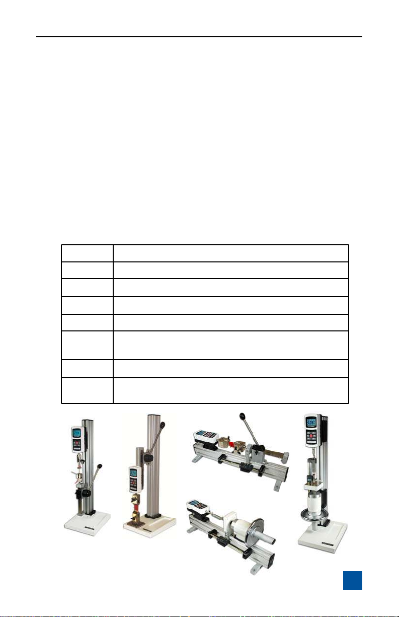
TSA750H
TSA750
TSB100
TSC1000H
TSC1000
3
Page 4

Series TS Force Measurement Test Stands
TSA750 / TSA750H
OPERATION
1. Mount the test stand to a firm, flat, and level working surface for maximum
safety and accuracy using four 5/16 screws (not included). Use the included
mounting hole drill template to accurately drill the holes. Testing can take
place without securing the test stand in such a manner, however, it is
strongly recommended that the stand be secured, especially for large forces.
2. Install a force gauge onto the gauge plate with four thumb screws. Mark-10
force gauges mount directly to the stand without adapters.
3. Install any needed attachments, including grips, adapters, and other materials necessary for your test sample. Make sure these items are set up in a
secure and safe manner.
4. Zero out the force gauge, then begin the test by turning the handwheel clockwise for compression or counter-clockwise for tension.
The loading lever can be adjusted to allow for ease of operation. Reposition the
loading lever by removing the knob and realigning the lever pin in the mounting
hub. Move the loading lever clockwise for compression, counter-clockwise for
tension.
The rack brake can be set by loosening the wing nut, positioning the rack to the
desired location and re-tightening the wing nut.
The clearance on the rack can be set by adjusting the four set screws using the
tools provided.
The travel stops can be adjusted in 0.5” [12.7 mm] increments along the rack by
moving the blocks to the desired location and tightening two screws. Fine adjustments can be made using adjusting screws on the housing and locking the jam
nuts.
Note: To maintain smooth functioning of the stand, avoid overloads and repetitive shock loads.
Optional Equipment
Digital Travel Display Kit – for accurate position indication
This position indicator covers 6” of travel per setting with a 5-digit display
(0.0005” resolution) and a computer interface for automated data collection. It
may be easily installed by the user.
4
Page 5

TSA750 / TSA750H
DIMENSIONS
in [mm]
TSA750
OPTIONAL
TRAVEL
DISPLAY
1.50 [38.1]
5/16-18 X 0.5 DP
BOTH ENDS
User’s Guide
3.00 [76.2]
MAX (MG)
11.00 [279.4]
10.00 [254.0]
MAX (EG/BG/M5)
25.8 [655]
3.00 [76.2]
10.00 [254]
]
]
4
0
.
.
2
7
5
2
1
1
[
[
0
0
0
0
.
.
6
5
]
2
.
6
7
[
0
0
.
3
]
2
.
6
7
[
0
0
.
3
TSA750H
7.90 [200.7]
]
1
.
8
3
[
0
5
.
1
OPTIONAL TRAVEL DISPLAY
15.00 [381.0]
MAX (MG)
14.00 [355.6]
MAX (EG/BG)
]
5
.
7
9
[
4
8
.
3
24.5 [622]
SPECIFICATIONS
Load capacity 750 lb [3750 N]
Maximum travel 6” / 3.75” [152.4 mm / 95.3 mm], with stops
Loading method / rate Rack & pinion / 3” [76.2 mm] per rev.
Weight (test stand, only) TSA750: 16 lb [7.3 kg], TSA750H: 13 lb [5.9 kg]
Optional digital travel
display resolution
0.0005” [0.01 mm]
5
Page 6

Series TS Force Measurement Test Stands
TSB100
OPERATION
1. Mount the test stand to a firm, flat, and level working surface for maximum
safety and accuracy using four 5/16 screws (not included). Use the included
mounting hole drill template to accurately drill the holes. Testing can take
place without securing the test stand in such a manner, however, it is recommended that the stand be secured.
2. Install a force gauge onto the gauge plate with four thumb screws. Mark-10
force gauges mount directly to the stand without adapters.
3. Install any needed attachments, including grips, adapters, and other materials necessary for your test sample. Make sure these items are set up
in a secure and safe manner.
4. Zero out the force gauge, then begin the test by turning the hand wheel
clockwise for compression or counter-clockwise for tension.
The loading lever can be adjusted to allow for ease of operation. Reposition the
loading lever by removing the knob and realigning the lever pin in the mounting
hub. Move the loading lever clockwise for compression, counter-clockwise for
tension.
The rack brake can be set by loosening the wing nut, positioning the rack to the
desired location and re-tightening the wing nut .
The clearance on the rack can be adjusted by removing the gauge plate, aligning the C-bracket holes with the set screws and adjusting as necessary.
Note: To maintain smooth functioning of the stand, avoid overloads and repetitive shock loads.
Optional Equipment
Digital Travel Display Kit – for accurate position indication
This position indicator covers 6” of travel per setting with a 5-digit display
(0.0005” resolution) and a computer interface for automated data collection. It
may be easily installed by the user.
6
Page 7

DIMENSIONS
in [mm]
OPTIONAL
TRAVEL
DISPLAY
User’s Guide
TSB100
3.00 [76.2]
REMOVABLE PLATE
WITH 25 #10-32 X 0.38
HOLES ON 0.5 [12.7] GRID
MAX (MG)
19.5 [495.3]
21.0 [533.4]
MAX (EG/BG)
SPECIFICATIONS
Load capacity 100 lb [500 N]
Maximum travel 6” / 3.75” with stops
[152.4 mm / 95.3 mm]
Loading method / rate Rack & pinion
3” [76.2 mm] per rev.
Weight (test stand, only) 12 lb [5.4 kg]
Optional digital travel display
resolution
0.0005“ [0.01 mm]
25.8 [655]
4.80 [121.9]
10.00 [254]
7
Page 8

Series TS Force Measurement Test Stands
TSC1000 / TSC1000H
OPERATION
1. Mount the test stand to a firm, flat, and level working surface for maximum
safety and accuracy using four 5/16 screws (not included). Use the included
mounting hole drill template to accurately drill the holes (TSC1000, only).
Testing can take place without securing the test stand in such a manner,
however, it is strongly recommended that the stand be secured, especially
for large forces.
2. Install a force gauge onto the gauge plate with four thumb screws. Mark-10
force gauges mount directly to the stand without adapters.
3. Install any needed attachments, including grips, adapters, and other materials necessary for your test sample. Make sure these items are set up
in a secure and safe manner.
4. Zero out the force gauge, then begin the test by turning the hand wheel
clockwise for compression or counter-clockwise for tension.
Note: To maintain smooth functioning of the stand, avoid overloads and repetitive shock loads.
Optional Equipment
Digital Travel Display Kit – for accurate position indication
This position indicator covers 6” of travel per setting with a 5-digit display
(0.0005” resolution) and a computer interface for automated data collection. It
may be easily installed by the user.
SPECIFICATIONS
Load capacity 1000 lb [5000 N]
Maximum travel 3.5” [88.9 mm]
Loading method / rate Handwheel
0.1” [2.54 mm] per rev.
Weight (test stand, only) TSC1000: 25 lb [9.0 kg],
TSC1000H: 20 lb [11.3 kg]
Digital travel display
(optional)
8
Resolution: 0.0005” [0.01 mm]
Page 9

TSC1000 / TSC1000H
DIMENSIONS
in [mm]
OPTIONAL
TRAVEL
DISPLAY
TSC1000
1.50 [38.1]
REMOVABLE PLATE
WITH 25 #10-32 X 0.38
HOLES ON 0.5 [12.7] GRID
User’s Guide
3.00 [76.2]
MAX (MG)
9.50 [241.3]
10.50 [266.7]
MAX (EG/BG/M5)
25.8 [655]
TSC1000H
7.90 [200.7]
]
1
.
8
3
[
0
5
.
1
OPTIONAL TRAVEL DISPLAY
13.5 [342.9]
MAX (MG)
12.5 [317.5]
MAX (EG/BG)
]
8
9
[
4
8
.
3
24.5 [622]
3.00 [76.2]
10.00 [254]
2
2
x
x
]
]
0
4
.
.
7
2
2
5
1
1
[
[
0
0
0
0
.
.
5
6
]
2
.
6
7
[
0
0
.
3
]
2
.
6
7
[
0
0
.
3
9
Page 10

Series TS Force Measurement Test Stands
WARRANTY
Mark-10 Corporation expressly warrants to its buyer for three (3) years from the
date of delivery that the goods sold are free from defects in workmanship and
materials. Mark-10 Corporation will, at its option, repair or replace or refund the
purchase price of goods found to be defective. This remedy shall be the buyer’s
sole and exclusive remedy. Any modification, abuse, exposure to corrosive environment or use other than intended will void this warranty. This warranty is in
lieu of all other warranties, including implied warranties of merchantabilit y and
fitness for an intended purpose. In no event shall Mark-10 Corporation be liable
for any incidental and consequential damages in connection with goods sold or
any part thereof.
10
 Loading...