

Page 1

-1-
01.0 Introduction . . . . . . . . . . . . . . . . . . . . . . . . . . . . . . . . . . . . . . . . . . . . . . . . . . . . . . . . 0
02.0 Quick Start Guide . . . . . . . . . . . . . . . . . . . . . . . . . . . . . . . . . . . . . . . . . . . . . . . . . . .
03.0 Keyboard, Menu and Connector Reference . . . . . . . . . . . . . . . . . . . . . . . . . . . . . . 1
04.0 Principles of Ultrasonic Measurement . . . . . . . . . . . . . . . . . . . . . . . . . . . . . . . . . . 1
05.0 Selecting the Measurement Mode . . . . . . . . . . . . . . . . . . . . . . . . . . . . . . . . . . . . . 2
06.0 Making Measurements . . . . . . . . . . . . . . . . . . . . . . . . . . . . . . . . . . . . . . . . . . . . . . . 2
07.0 Using the Digits & B-Scan Displays . . . . . . . . . . . . . . . . . . . . . . . . . . . . . . . . . . . . 3
08.0 Thru Paint Measurement Technique . . . . . . . . . . . . . . . . . . . . . . . . . . . . . . . . . . . . 3
09.0 Pulse-Echo Coating & Coating Techniques . . . . . . . . . . . . . . . . . . . . . . . . . . . . . . 3
10.0 Additional Features TI-CMXDL . . . . . . . . . . . . . . . . . . . . . . . . . . . . . . . . . . . . . . . . 4
11.0 Data Storage - Set-Up, Edit, & View Files . . . . . . . . . . . . . . . . . . . . . . . . . . . . . . . . 4
12.0 Setups — Create, Store, Edit & Recall . . . . . . . . . . . . . . . . . . . . . . . . . . . . . . . . . . 5
13.0 Using the Utility Software . . . . . . . . . . . . . . . . . . . . . . . . . . . . . . . . . . . . . . . . . . . . 6
14.0 Low Battery Indicator and Changing the Battery . . . . . . . . . . . . . . . . . . . . . . . . . 6
Appendix A — Velocity Table . . . . . . . . . . . . . . . . . . . . . . . . . . . . . . . . . . . . . . . . . . . . . . .
6
Warranty
TABLE OF CONTENTS
-68-
NOTES
Page 2
1.0 INTRODUCTION
The Electromatic TI-CMXDL is an ultrasonic thickness gauge that measures with extreme
versatility. It has the ability to simultaneously measure coatings and material thicknesses while
maintaining the ability to locate pits, flaws and defects in the material. Based on the same
operating principles as SONAR, the TI-CMXDL is capable of measuring the thickness of various
materials with accuracy as high as ± 0.001 inches, or ± 0.01 millimeters. The principle advantage
of ultrasonic measurement over traditional methods is that ultrasonic measurements can be
performed with access to only one side of the material being measured.
NOTE: Inherent in ultrasonic thickness measurement is the possibility that the instrument will
use the second rather than the first echo from the back surface of the material being
measured. This may result in a thickness reading that is TWICE what it should be.
Responsibility for proper use of the instrument and recognition of this phenomenon rest
solely with the user of the instrument. Other errors may occur from measuring coated
materials where the coating is insufficiently bonded to the material surface. Irregular
and inaccurate readings may result. Again, the user is responsible for proper use and
interpretation of the measurements acquired.
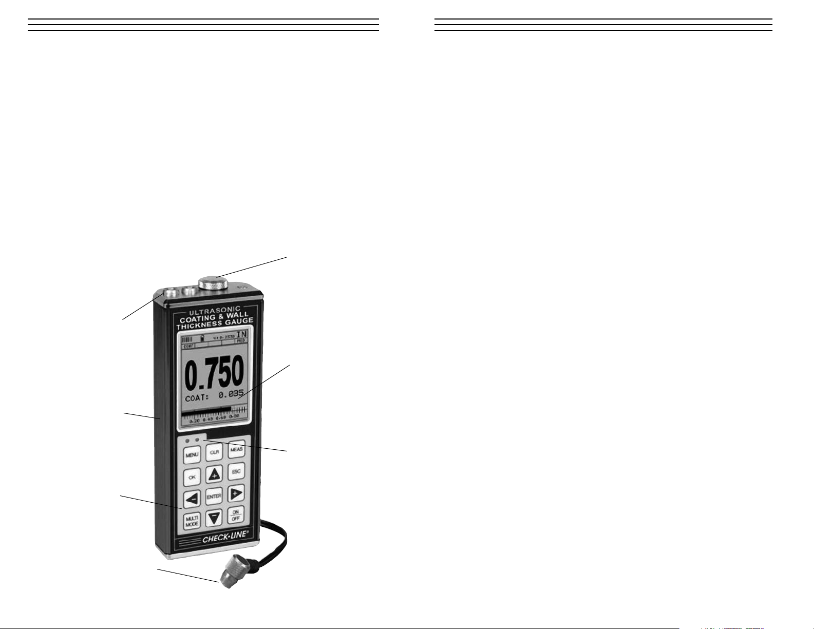
1.1 Overview
-2-
Probe
Keypad
Aluminum
Housing
LCD Backlit
Display
LED Alarm
Indicators
Probe
Receptacles
Probe Zero Plate
& Battery Cover
(3x AAA alkaline
batteries installed)
-67-
WARRANTY
ELECTROMATIC Equipment Co., Inc. (ELECTROMATIC) warrants to the
original purchaser that this product is of merchantable quality and confirms
in kind and quality with the descriptions and specifications thereof. Product
failure or malfunction arising out of any defect in workmanship or material in the
product existing at the time of delivery thereof which manifests itself within one
year from the sale of such product, shall be remedied by repair or replacement of
such product, at ELECTROMATIC’s option, except where unauthorized repair,
disassembly, tampering, abuse or misapplication has taken place, as determined by
ELECTROMATIC. All returns for warranty or non-warranty repairs and/or replacement must be authorized by ELECTROMATIC, in advance, with all repacking and
shipping expenses to the address below to be borne by the purchaser.
THE FOREGOING WARRANTY IS IN LIEU OF ALL OTHER WARRANTIES,
EXPRESSED OR IMPLIED, INCLUDING BUT NOTLIMITED TO, THE
WARRANTY OF MERCHANTABILITY AND FITNESS FOR ANY PARTICULA
PURPOSE OR APPLICATION. ELECTROMATIC SHALL NOT BE RESPONSIB
NOR LIABLE FOR ANY CONSEQUENTIAL DAMAGE, OF ANY KIND OR
NATURE, RESULTING FROM THE USE OF SUPPLIED EQUIPMENT, WHETH
SUCH DAMAGE OCCURS OR IS DISCOVERED BEFORE, UPON OR AFTER
REPLACEMENT OR REPAIR, AND WHETHER OR NOT SUCH DAMAGE IS
CAUSED BY MANUFACTURER’S OR SUPPLIER’S NEGLIGENCE WITHIN
ONE YEAR FROM INVOICE DATE.
Some State jurisdictions or States do not allow the exclusion or limitation of inciden
or consequential damages, so the above limitation may not apply to you. The duratio
of any implied warranty, including, without limitation, fitness for any particular
purpose and merchantability with respect to this product, is limited to the duration
of the foregoing warranty. Some states do not allow limitations on how long an
implied warranty lasts but, not withstanding, this warranty, in the absence of such
limitations, shall extend for one year from the date of invoice.
ELECTROMATIC Equipment Co., Inc.
600 Oakland Ave. Cedarhurst, NY 11516—USA
Tel: 1-800-645-4330/ Tel: 516-295-4300/ Fax: 516-295-4399
Every precaution has been taken in the preparation of this manual. Electromatic Equipment Co., Inc., assum
no responsibility for errors or omissions. Neither is any liability assumed for damages resulting from the use
information contained herein. Any brand or product names mentioned herein are used for identification purp
es only, and are trademarks or registered trademarks of their respective holders.
Page 3
2.0 QUICK-STAR T GUIDE
Turn the TI-CMXDL on and off using the switch located on the bottom right corner of the key
pad. When TI-CMXDL is initially turned on, a flash logo and blinking lights are displayed. Th
the gauge attempts to identify the currently attached transducer (probe). The TI-CMXDL has a
“Auto Probe Recognition” feature that attempts to identify special transducers with feature bui
in . If the TI-CMXDL doesn’t find a transducer so equipped, the user must select a transducer
from the Probe Type list. The following sections outline each scenario.
NOTE: This section is primarily written as a basic startup guide only.
2.1 TI-CMXDL Overview
In order to understand how to operate the TI-CMXDL, it’s best to start off with an
understanding of what it is we’re looking at exactly. The TI-CMXDL has a lot of great
features and tools that will prove to be a huge benefit for the variety of applications you
constantly facing on a continual basis. Let’s have a brief look at the screens you’ll be
ºlooking at most often:
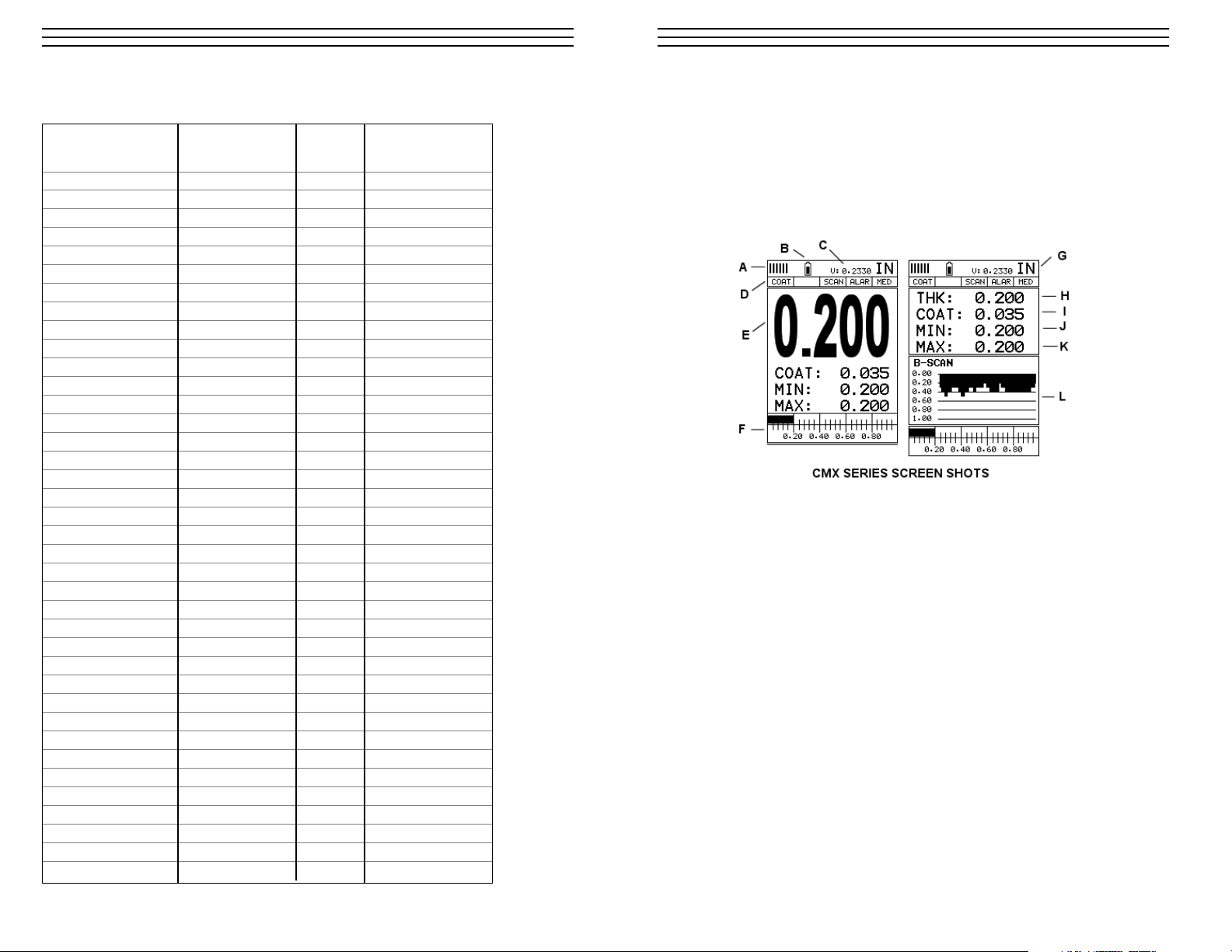
A. Repeatability/Stability Indicator – This indicator should be commonly used in con
junction with the digital thickness values displayed. When all the vertical bars are ful
illuminated and the last digit on the digital thickness value is stable, the TI-CMXDL
reliably measuring the same value 3 to 200 times per second, depending on which
measurement mode and features are enabled.
B. Battery Icon – Indicates the amount of battery life the TI-CMXDL has remaining.
C. Velocity – The material velocity value the TI-CMXDL is currently using or calibrated
Displayed in English or Metric units, depending on the what units the gauge is set for.
D. Feature Status Bar – Indicates the features currently enabled and in use in the
following order:
• Measurement Mode
• Differential Mode
• High Speed Scan Mode
• Alarm Mode
• Gain Setting
E. Digital Material Thickness Value – Extra large font size for viewing ease.
-3--66-
APPENDIX A: VELOCITY TABLE
Material sound velocity sound velocity
in/us m/s
Aluminum 0.2510 6375
Beryllium 0.5080 12903
Brass 0.1730 4394
Bronze 0.1390 3531
Cadmium 0.1090 2769
Columbium 0.1940 4928
Copper 0.1830 4648
Glass (plate) 0.2270 5766
Glycerine 0.0760 1930
Gold 0.1280 3251
Inconel 0.2290 5817
Iron 0.2320 5893
Cast Iron 0.1800 (approx) 4572
Lead 0.0850 2159
Magnesium 0.2300 5842
Mercury 0.0570 1448
Molybdenum 0.2460 6248
Monel 0.2110 5359
Nickel 0.2220 5639
Nylon 0.1060 (approx) 2692
Platinum 0.1560 3962
Plexiglas 0.1060 2692
Polystyrene 0.0920 2337
PVC 0.0940 2388
Quartz glass 0.2260 5740
Rubber vulcanized 0.0910 2311
Silver 0.1420 3607
Steel (1020) 0.2320 5893
Steel (4340) 0.2330 5918
Steel Stainless" 0.2230 5664
Teflon 0.0540 1372
Tin 0.1310 3327
Titanium 0.2400 6096
Tungsten 0.2040 5182
Uranium 0.1330 3378
Water 0.0580 1473
Zinc 0.1660 4216
Zirconium 0.1830 4648
Page 4
F. Scan Bar – Another view of material thickness in a deflection style horizontal bar. This
visual tool enables the user the ability to see thickness changes during high speed scans
from flaws and pits.
G. Units – The current measurement units being used (English, Metric).
H. Digital Material Thickness Value – Smaller font size when the B-Scan display
view is enabled.
I. Coating Thickness Value – Displays the actual thickness of any coating adhered
to a metallic material surface (PECT Mode), or a coating adhered to a non-metallic
surface (CT Mode).
J. Minimum Material Thickness – Part of the Alarm feature. Displays the minimum
thickness value found during a scan.
K. Maximum Material Thickness – Part of the Alarm feature. Displays the maximum
thickness value found during a scan.
L. B-Scan Display – Cross section view of the material. Provides the user with graphical
view of the opposite/blind surface (i.e. inside pipe wall surface), to give the user some
idea of the condition, or integrity of the material being tested.
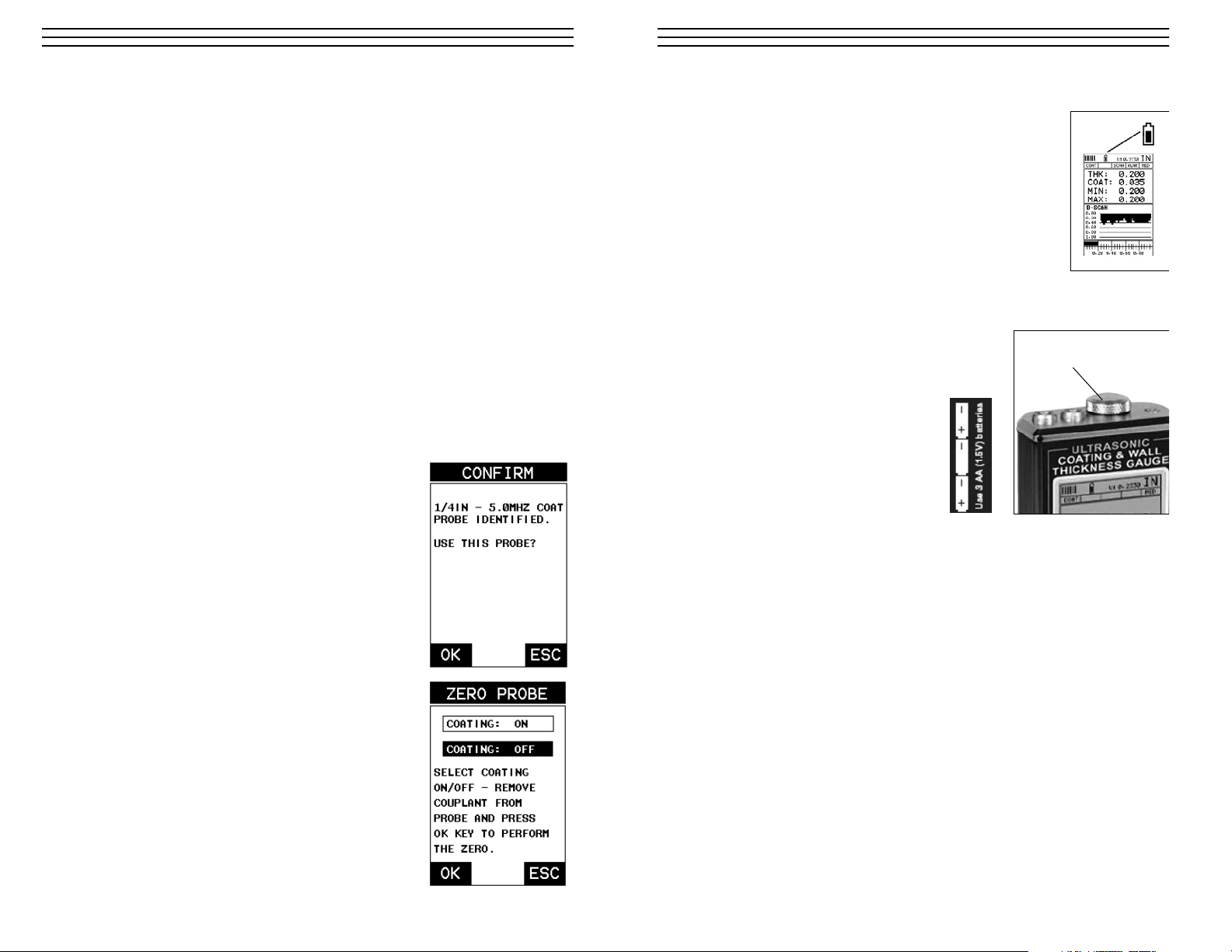
2.2 Auto Probe Recognition
When the TI-CMXDL is initially powered up, the gauge will automatically check to see if
the transducer plugged into the gauge can be recognized. The steps that follow assume the
TI-CMXDL recognized the probe type:
1. Press the OK key once to use the identified probe,
or ESC to display a list of optional transducers.
NOTE: If the TI-CMXDL recognizes a specific
transducer, the user should always select OK
to use the identified probe. The only time an
alternative probe should be selected from a list
is if the user switched probes following initial
power up and recognition.
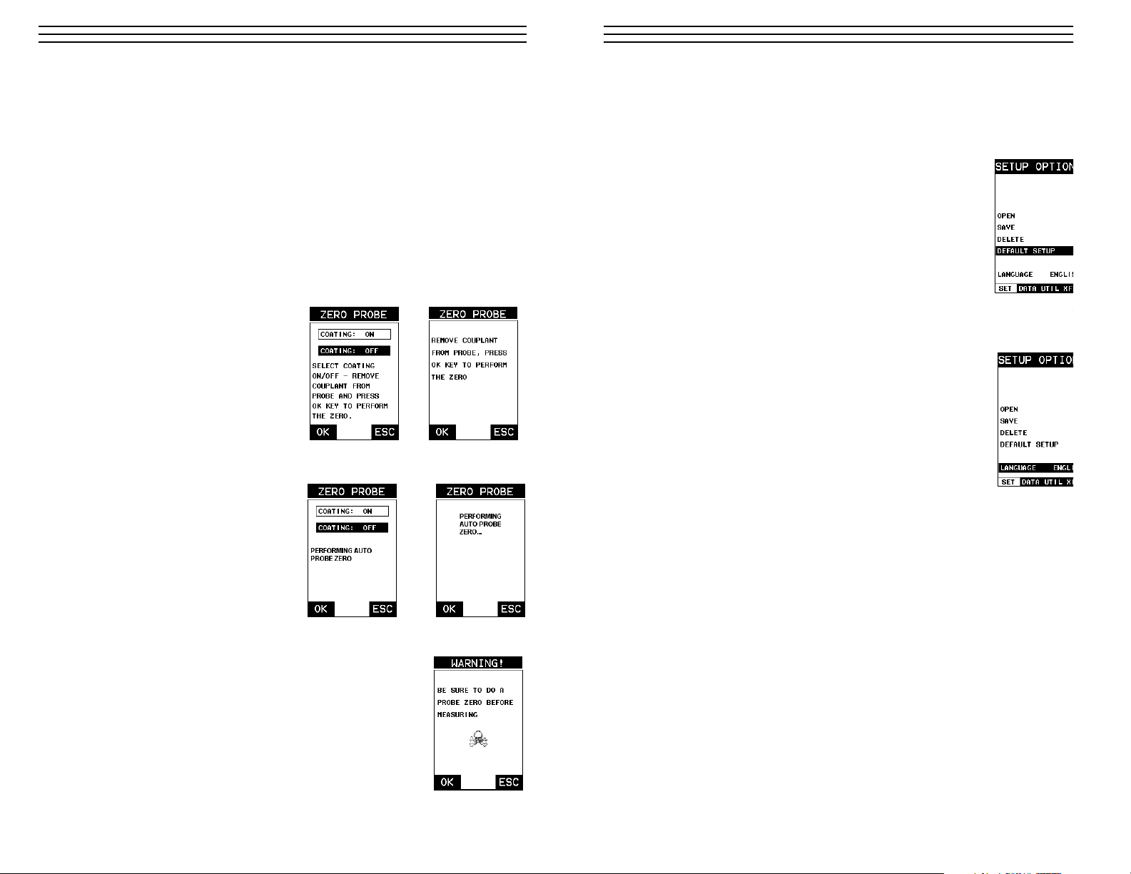
2. Assuming the TI-CMXDL recognized the probe and
the OK key was pressed, the TI-CMXDL will
advance to a Zero Probe menu. If the transducer was
identified as a special transducer capable of measuring
coating thickness, a menu will be displayed allowing
the user the ability to toggle the coating thickness
display on/off as follows:
3. Press the UP and DOWN arrow keys to toggle the
coating option on/off.
4. Wipe all couplant from the transducer face
and advance to the Probe Zero & Calibration
section, 6.0.
-4-
-65-
14.0 LOW BAT TE RY INDICATOR & CHANGING THE BATTERIES
The TI-CMXDL has a Battery Strength Indicator (illustrated here) that
provides the user with information about the remaining strength of the
batteries. There are 11 steps from 100% (full) to 0% (empty). As the
battery voltage drops, the number of pixels that are dark will be reduced.
When the battery outline is nearly empty, we suggest changing the
bateries. Any type of AA size battery can be used including alkaline
(1 time use) or rechargeable.
There is no re-charging function provided with this gauge, so
rechargeable batteries will have to be recharged externally. Please
note that alkaline batteries will provide a longer run time then most
rechargeable types.
14.1 Battery Replacement
The battery cover is the large round disk shown in
the photo. This disk is also the Proble Zero Plate.
To remove it and expose the batteries, unscrew the
disk by carefully turning it counterclockwise.
Remove the old batteries and insert three
fresh AA batteries with the polarity as
indicated here (also shown on the label
on the back side of the gauge). Replace
the battery cover being careful not to over
tighten.
Battery Cover &
Probe Zero Plate
Page 5
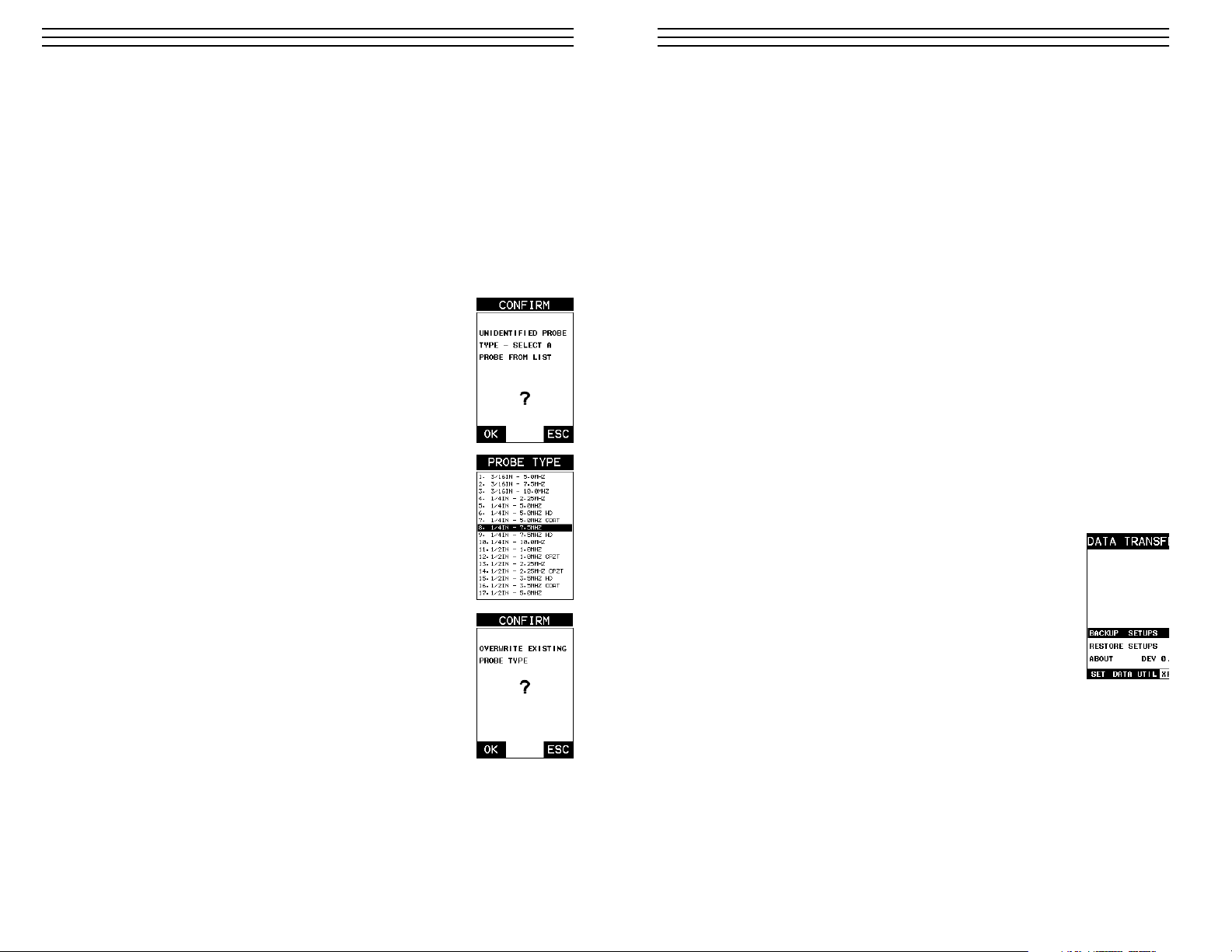
2.3 Selecting the Transducer Type
If the TI-CMXDL does not identify a specific transducer type on initial power up, the user
will be required to select a type from a predefined list of types by diameter and frequency.
By selecting a transducer type from a predefined list, the TI-CMXDL can recall specific
properties about the transducer.
NOTE: Once the transducer has been selected, the TI-CMXDL will store and recall this
transducer type every time the TI-CMXDL is powered on/off. The type will only change if
the user physically selects another transducer type from the list, or selects a previously
saved setup. However, the TI-CMXDL will continue to take you through these steps each
time the gauge is powered up. You’ll notice that the probe type previously selected will be
highlighted every time the probe type screen is displayed. Use the following steps to select
your transducer type:
1. Press the OK or ESC keys to display the factory list of
transducer types (by diameter and frequency).
2. Press the UP and DOWN arrow keys to scroll through the
transducer list until the appropriate type is highlighted.
3. Press the ENTER key to select the transducer type and display
over write existing probe screen.
4. Press the OK key to overwrite the existing probe type with the
newly selected probe type. The zero probe screen will be
displayed. Proceed to the zero probe section that follows.
-5-
13.0 USING THE UTILITY SOFTWARE
13.1 Computer System Requirements
Datacomm will run on many different operating systems: Windows 98 (1st or 2nd editio
Windows NT 4.0 with Service Pack 5, Windows ME, Windows XP, Windows 2000
Professional, Windows 2000 Server, or Windows 2000 Advanced Server operating syste
running on Intel or AMD hardware.
A Pentium 166MHz or faster processor with at least 32 megabytes of physical RAM is
required. You should have 40 megabytes of free disk space before attempting to install
Datacomm.
Datacomm requires an available communications port in order to transfer data to and fro
the TI-CMXDL. Datacomm supports COM1, COM2, COM3, and COM4.
USB to Serial Converter
Some newer laptop computers do not have standard serial ports. In this case it is possibl
use a USB to Serial converter. If a serial to USB cable is needed, contact Electromatic
13.2 Installing Datacomm
Datacomm comes on a CD-ROM with an automatic installer program. Place the CD in
your computer’s CD tray and close the door. Open the CD-ROM by double clicking on
My Computer ICON, then double click on the CD. Finally, double click on the SETUP
icon to begin the installation.
Refer to the help section in Datacomm software for the complete operating manual, setu
and operation.
13.3 Using the XFER menu (TI-CMXDL)
The XFER menu of the TI-CMXDL will be used in conjunction
with the Datacomm PC software. The steps below outline the procedure for accessing the XFER menu and basic operation as follows:
1. Press the MENU key once to activate the menu items tab. Press
the MENU key multiple times to tab right, and the ESC key
multiple times to tab left, until the XFER menu is highlighted
and displaying the submenu items.
2. Use the UP and DOWN arrow keys to scroll through the
sub menu items until the desire option is highlighted.
3. Press the ENTER key to activate the option selected.
4. Once the Backup or Restore function has been completed, press the MEAS key once
return to the menu items, or twice to return to the measurement mode.
-64-
Page 6
2.4 Probe Zero & One Point Calibration
The next steps are to perform a probe zero and calibrate the TI-CMXDL to the material
and transducer being used. If the sound velocity is unknown, the TI-CMXDL can be
calibrated to a known thickness sample. This demo will briefly explain both of these
techniques.
The TI-CMXDL is equipped with two zero options:
• Off Block Zero (Automatic Probe Zero) – When this feature is enabled the
TI-CMXDL will do an electronic zero automatically, eliminating the need for a zero
disk or block.
• On Block Zero (Manual Probe Zero) – When this feature is enabled the transducer
must be placed on the probe zero disk (battery cover located on the top of the unit.
NOTE: Transducers of the same type will have very slight mechanical and electrical
variations. If it’s discovered that the linearity is off following an initial auto probe zero
and extreme accuracy is required, a
manual zero should be performed
followed by an auto zero. This will
adjust and eliminate any error. This is
only required if it’s discovered the
transducer is non-linear following
an initial auto probe zero.
Both zero procedures are outlined
as follows:
Off Block Zero (Automatic Probe Zero)
1. Be sure all couplant has been removed
from the face of the transducer.
2. Press the OK key to perform the
automatic probe zero, or ESC key
to cancel the zero operation.
3. The screens illustrated at the right
will be briefly displayed followed by
the main measurement screen. The
TI-CMXDL is ready to be calibrated.
-6-
Coating Probe
Identified
Coating Probe
Not Identified
Coating Probe
Identified
Coating Probe
Not Identified
Performing a Manual Probe Zero (On Block)
NOTE: When the zero probe option is set to manual, the probe
zero disk (battery cap) located on the top of the gauge, will be
used as a zero standard and the warning screen illustrated
above will be displayed.
1. Press the OK or ESC keys to enter the main measurement
screen and begin the manual zero process.
2. Apply a drop of couplant on the transducer and place the
transducer in steady contact with the probe zero disk, and
obtain a steady reading.
12.5 Using the Default Setup
The default setup feature was added to the CMX to use, as a last resort, if there are no
setups stored in the gauge –factory or otherwise. The only time this might possibly occu
if the setup file in the CMX was somehow corrupted, and the user does not have access
computer to re-load the factory setups back into the CMX. This gives the user the ability
load and modify a basic setup as follows:
1. Press the MENU key once to activate the menu items tab.
Press the MENU key multiple times to tab right and the
ESC key multiple times to tab left until the SETUP menu
is highlighted and displaying the submenu items.
2. Use the UP and DOWN arrow keys to scroll through the
sub menu items until DEFAULT SETUP is highlighted.
12.6 Selecting a Language
The CMX is equipped with a language option. Currently, the only languages supported a
English, Spanish, and German. The steps to select one of these languages are outlined a
follows:
1. Press the MENU key once to activate the menu items tab.
Press the MENU key multiple times to tab right and the
ESC key multiple times to tab left until the SETUP menu is
highlighted and displaying the submenu items.
2. Use the UP and DOWN arrow keys to scroll through the
sub menu items until LANGUAGE is highlighted.
3. Press the LEFT and RIGHT arrow keys to toggle the
language options.
4. Once the desired language is displayed, press the MEAS
key to return to the measurement screen.
-63-
Page 7
3. Press the MENU key once to activate the menu items tab.
Press the MENU key multiple times to tab right and the
ESC key multiple times to tab left until the PRB menu is
highlighted and displaying the submenu items.
4. Press the UP and DOWN arrow keys to scroll through the
sub menu items until ZERO PROBE is highlighted.
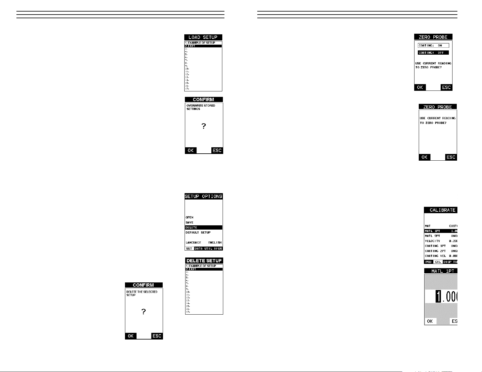
5. Press the ENTER key to display the confirmation screen.
6. If a coating transducer was identified use the UP and
DOWN arrow keys to toggle coating on/off.
7. Press the OK key to complete the probe zero function, or
ESC key to cancel the probe zero function.
8. Remove the transducer from the probe zero disk, and
proceed to the calibration section.
NOTE: The value that is displayed will change depending on
the current velocity setting in the TI-CMXDL. Disregard the
number that is displayed. It is not important. What is important is
accurately performing the steps outlined above to insure
reliability of the probe zero calculation.
One Point Material Calibration
For the purposes of this quick start section, we’ll only be covering the most common on
point calibration option to determine the sound velocity of the test material. It would be
very handy to carry a set of mechanical calipers to use in conjunction with the TI-CMXD
for calibration in the field:
NOTE: Be sure that the probe zero procedure has been
performed prior to performing this calibration procedure.
1. Physically measure an exact sample of the material or a
location directly on the material to be measured using a
set of calipers or a digital micrometer.
2. Apply a drop of couplant on the transducer and place the
transducer in steady contact with the sample or actual test
material. Be sure that the reading is stable and the repeatability indicator, in the top left corner of the display, is fully
lit and stable. Press the MENU key once to activate the menu
items tab. Press the MENU key multiple times to tab right
and the ESC key multiple times to tab left until the CAL
menu is highlighted and displaying the submenu items.
3. Use the UP and DOWN arrow keys to scroll through the
sub menu items until MATL 1PT is highlighted.
4. Press the ENTER key to display the Digits Edit Box.
5. Press the UP and DOWN arrow keys to scroll the highlighted
value.
6. Press the LEFT and RIGHT arrow keys to scroll the digit
locations.
-7-
Coating Probe
Identified
Coating Probe
Not Identified
10. Press the ENTER key to activate the Setup List Box.
11. Use the UP and DOWN arrow keys to scroll through the setups
until the target location to save the Setup is highlighted.
12. Press the OK key to activate the confirmation screen.
13. Press the OK key to save the Setup, or ESC to cancel saving
the Setup.
14. Finally, press the MEAS key to return to the measurement
screen.
NOTE: The Name and Comments of the Setup can be edited at
any time by simply repeating the Save Setup routine described
above. Therefore, the Save Setup function can also be considered
an Edit Function.
12.4 Deleting a Saved Setup
This option allows a user to delete setup files that were previously saved and no longer
needed. It’s a simple feature to allow the user to do a bit of “house cleaning”.
1. Press the MENU key once to activate the menu items tab. Press
the MENU key multiple times to tab right and the ESC key
multiple times to tab left until the SETUP menu is highlighted
and displaying the submenu items.
2. Use the UP and DOWN arrow keys to scroll through the
sub menu items until DELETE is highlighted.
3. Press the ENTER key to display the Setups List.
4. Press the UP and DOWN arrow keys to scroll to the
Setup Name.
5. When the Setup Name is highlighted, press the ENTER key
to display the confirmation screen.
6. Press the OK key to delete the Setup File.
7. Finally, press the MEAS key to
return to the measurement screen.
-62-
Page 8
7. Repeat steps 5 & 6 until the known thickness value is correctly displayed.
8. Press the OK key to calculate the velocity and return to the menu screen,
or ESC to cancel the one point calibration.
9. Finally, press the MEAS key to return to the measurement screen and begin
taking readings.
NOTE: CHECK YOUR CALIBRATION! Place the transducer back on the calibration
point. The thickness reading should now match the known thickness. If the thickness is not
correct, repeat the steps above.
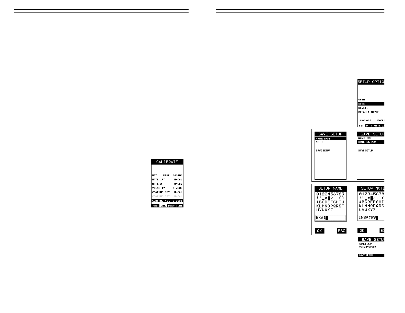
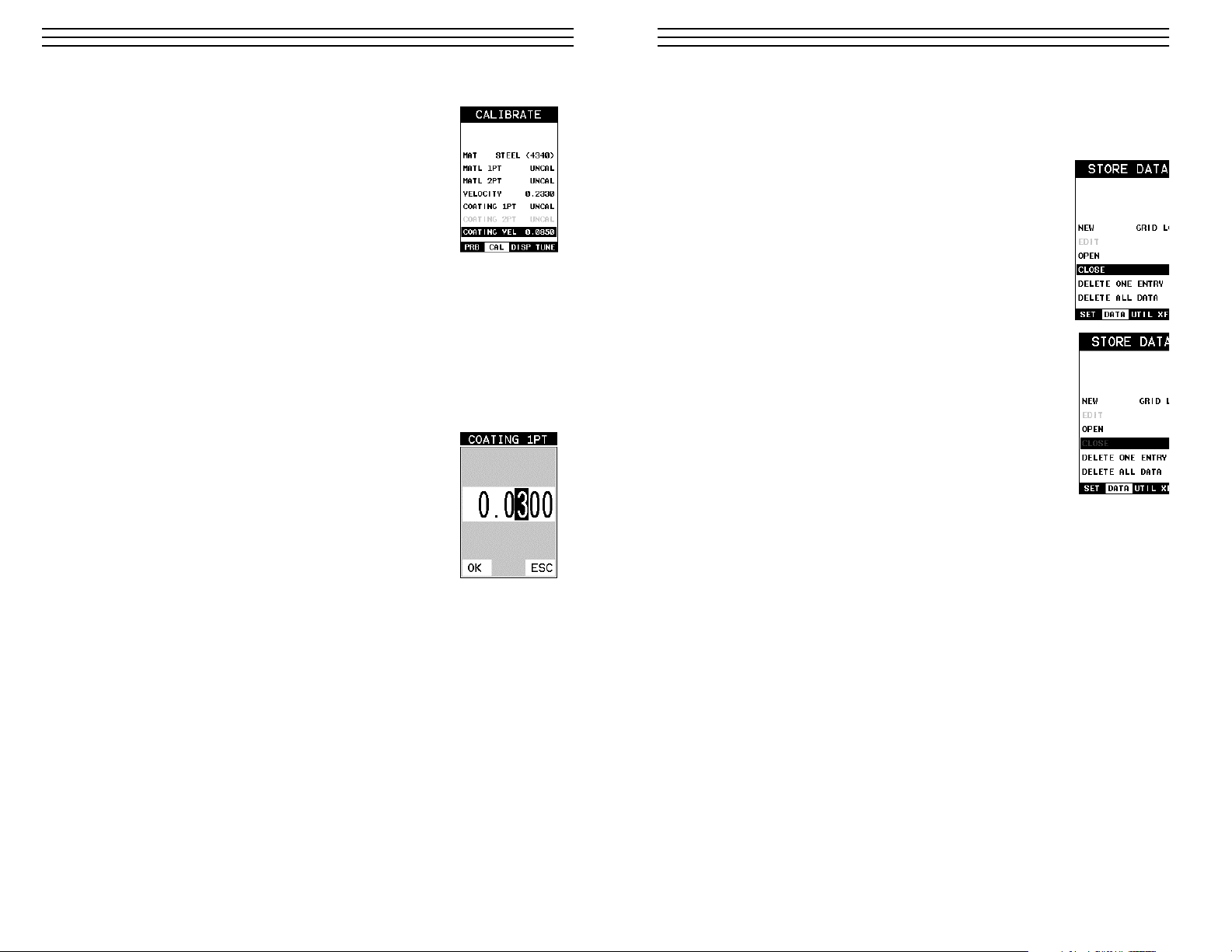
2.5 Coating Calibration
The TI-CMXDL has been preset to a default coating velocity of 0.0850 in/µsec (2159
m/sec). This will be very close to the most common coating material velocities used in the
field.
If the velocity of the coating is known, and different than the above default setting, the
user can simply enter the coating velocity into the TI-CMXDL. However, if the velocity
is unknown, the TI-CMXDL can also be calibrated to a specific coating sample/type using
the 1pt calibration option in PECT (pulse-echo coating) mode, or a two point calibration is
CT (coating only) mode. For the purpose of this quick start section only the 1pt option
PECT (pulse-echo coating) mode will be covered. Refer to the calibration section of the
manual for a complete explanation on the coating calibration options. The following steps
below outline the necessary steps to either set the velocity of the coating, or perform a one
point calibration to calculate the coating velocity:
Known Coating Velocity
If the coating velocity is known, the user may wish to simply
enter the velocity number into the TI-CMXDL, rather than have
the TI-CMXDL calculate the velocity value using a known thickness on a coating sample. The steps for entering the velocity are
outlined below:
1. Press the MENU key once to activate the menu items tab.
Press the MENU key multiple times to tab right and the
ESC key multiple times to tab left until the CAL menu is
highlighted and displaying the submenu items.
2. Use the UP and DOWN arrow keys to scroll through the sub menu items until
COATING VEL is highlighted.
3. Press the ENTER key to display the Digits Edit Box.
4. Press the UP and DOWN arrow keys to scroll the highlighted value.
5. Press the LEFT and RIGHT arrow keys to scroll the digit locations.
6. Repeat steps 4 & 5 until the velocity number is correctly displayed.
7. Press the OK key to set the coating velocity and return to the menu screen,
or ESC to cancel entering the coating velocity.
8. Finally, press the MEAS key to return to the measurement screen and begin taking
readings
-8-
12.3 Saving a Setup
Once the TI-CMXDL parameters and features have be adjusted for an application, the u
may elect to save these setting to a specific setup location for future use. This can poten
tially save time and reduce error between users.
It is sometimes necessary to rename a previously saved setup, or add additional commen
about a particular setup. The setup name may have been entered incorrectly, or the user
needs to use the setup for a completely different project. An inspector’s name or other co
ments about the project may also be required for additional documentation purposes. Th
following procedures outline the necessary steps for saving and editing a setup:
1. Press the MENU key once to activate the menu items tab. Press
the MENU key multiple times to tab right and the ESC key
multiple times to tab left until the SETUP menu is highlighted
and displaying the submenu items.
2. Use the UP and DOWN arrow keys to scroll through the
sub menu items until SAVE is highlighted.
3. Press the ENTER key to display the Save Setup Parameters
List Box.
4. Press the UP and DOWN arrow keys to
scroll the Name and Note
5. When the parameter to edit is highlighted, press the ENTER key to
activate the Alpha Edit Box.
6. Use the UP, DOWN, LEFT, and
RIGHT arrow keys to scroll through
the characters, the ENTER key to
select characters, and the CLR key to
backspace through the characters, until
the Name or Note fields have been
edited.
7. Press the OK key to return to the Save
Setup Parameters List Box.
8. If both parameters will be edited,
repeat steps 4 – 7.
9. Use the UP and DOWN arrow keys to scroll to and highlight
SAVE SETUP.
-61-
Page 9
Known Coating Thickness
When the exact velocity of a coating is unknown, the user has
the option of performing a one point calibration on a sample of
the coating with a known thickness to determine the sound
velocity. It would be very handy to carry a set of mechanical
calipers to use in conjunction with the TI-CMXDL for calibration in the field:
1. Physically measure a location on a coating sample using a set
of calipers or a digital micrometer.
IMPORTANT NOTE: In PECT (pulse-echo coating) mode, the
coating sample must be coupled to metal in order to calibrate
successfully. Simply place a drop of couplant on a piece of
metal, lay the coating sample over the couplant on the metal and
proceed to step 2.
2. Apply a drop of couplant on the transducer and place the transducer in steady contact
with the coating (on metal) sample or actual test material. Be sure that the reading is
stable and the repeatability indicator, in the top left corner of the display, is fully lit and
stable. Press the MENU key once to activate the menu items tab. Press the MENU key
multiple times to tab right and the ESC key multiple times to tab left until the CAL
menu is highlighted and displaying the submenu items.
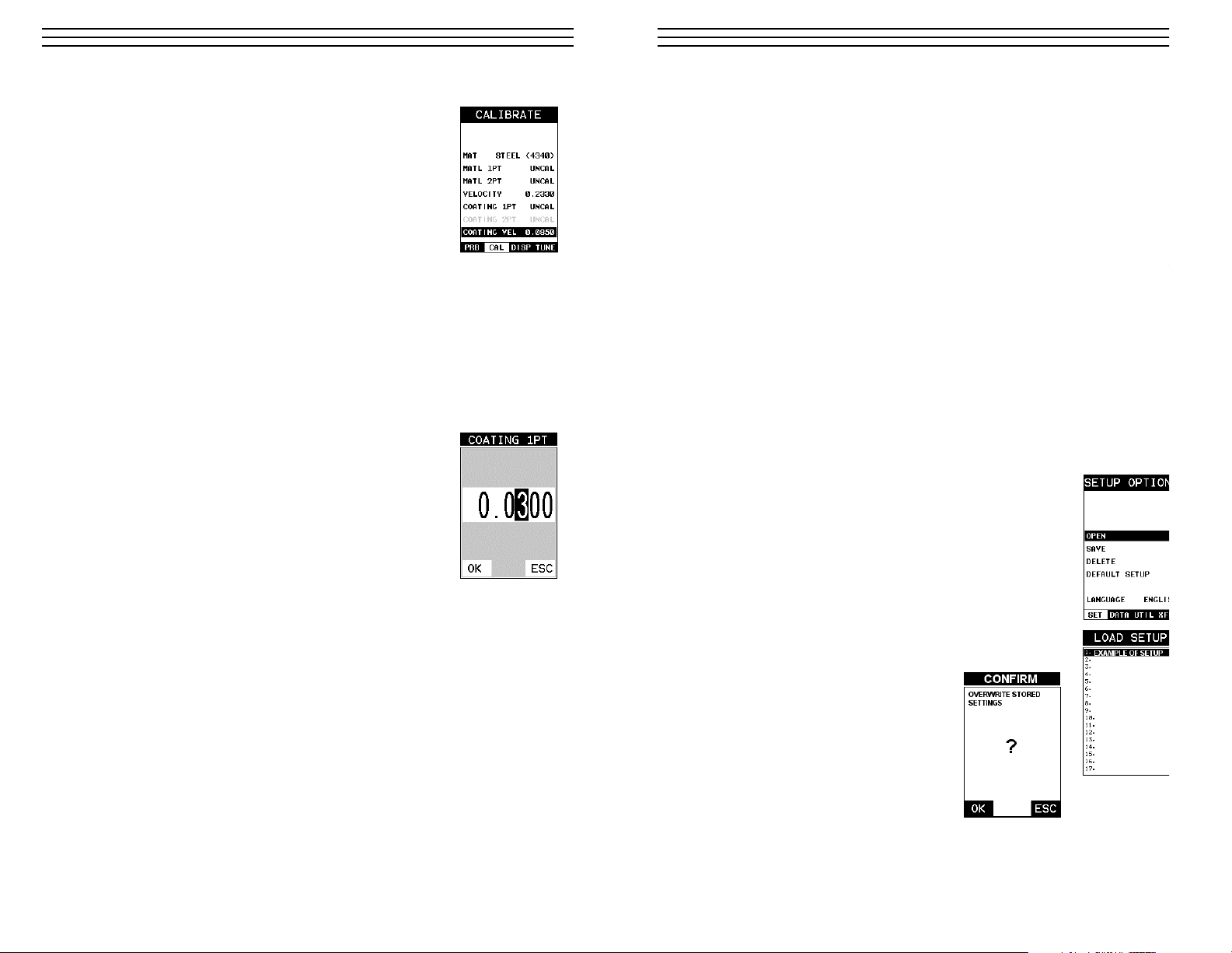
3. Use the UP and DOWN arrow keys to scroll through the
sub menu items until COATING 1PT is highlighted.
4. Press the ENTER key to display the Digits Edit Box.
5. Press the UP and DOWN arrow keys to scroll the
highlighted value.
6. Press the LEFT and RIGHT arrow keys to scroll the digit
locations.
7. Repeat steps 5 & 6 until the known thickness value is
correctly displayed.
8. Press the OK key to calculate the coating velocity and return
to the menu screen, or ESC to cancel the one point calibration.
9. Finally, press the MEAS key to return to the measurement screen and begin taking
readings.
NOTE: CHECK YOUR CALIBRATION! Place the transducer back on the calibration
point. The coating thickness reading should now match the known coating thickness sample. If the thickness is not correct, repeat the steps above.
-9-
12.0 SETUPS, CREATE, STORE, EDIT & RECALL
12.1 Introduction to Setups
Often times, users are faced with a variety of tasks and applications that are sometimes
similar, but often times very different. With a standard thickness gauge, the user would
have to recalibrate for each individual application respectively. With all the features of th
TI-CMXDL, the number of potential applications also increases based on ability alone.
This is primarily in reference to the addition of those very difficult applications, where a
standard thickness gauge would not be feasible, or capable of accomplishing the tasks.
The increased number of features and parameters also adds to the overall setup time, or
amount of time to set up marginal applications with perfection and understanding. Becau
of the additional time involved, the TI-CMXDL has been equipped with the ability to sa
these setups to memory and be recalled at any time. The TI-CMXDL can store up to 64
custom setups. These setups can be bi-directionally transferred to and from a PC.
Therefore, the user can save as many setups as necessary for all their individual applications requirements. This saves a great deal of time and knowledge for future inspections
the same job or project. This feature also eliminates error between two or more users du
ing the setup and calibration process.
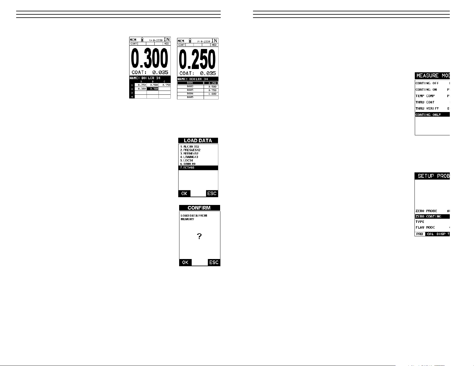
12.2 Opening a Setup
Once user setups are saved (refer to Section 11.3, p. 47), they are opened (recalled for u
using the following procedure. Please make sure that the correct probe is connected and
matches the probe selection stored in this setup.
1. Press the MENU key once to activate the menu items tab.
Press the MENU key multiple times to tab right and the
ESC key multiple times to tab left until the SETUP menu is
highlighted and displaying the submenu items.
2. Use the UP and DOWN arrow keys to scroll through the
sub menu items until OPEN is highlighted.
3. Press the ENTER key to display the Setup List Box.
4. Use the UP and DOWN arrow keys to scroll through the
setups until the target setup is highlighted.
5. Press the ENTER key to activate the confirmation screen.
6. Press the OK key to load the setup
from memory.
7. Press the MEAS key to return to the
measure screen.
-60-
Page 10
Known Coating Thickness
When the exact velocity of a coating is unknown, the user has
the option of performing a one point calibration on a sample of
the coating with a known thickness to determine the sound
velocity. It would be very handy to carry a set of mechanical
calipers to use in conjunction with the TI-CMDL for calibration
in the field:
1. Physically measure a location on a coating sample using a set
of calipers or a digital micrometer.
IMPORTANT NOTE: In PECT (pulse-echo coating) mode, the
coating sample must be coupled to metal in order to calibrate
successfully. Simply place a drop of couplant on a piece of
metal, lay the coating sample over the couplant on the metal and
proceed to step 2.
2. Apply a drop of couplant on the transducer and place the transducer in steady contact
with the coating (on metal) sample or actual test material. Be sure that the reading is
stable and the repeatability indicator, in the top left corner of the display, is fully lit and
stable. Press the MENU key once to activate the menu items tab. Press the MENU key
multiple times to tab right and the ESC key multiple times to tab left until the CAL
menu is highlighted and displaying the submenu items.
3. Use the UP and DOWN arrow keys to scroll through the
sub menu items until COATING 1PT is highlighted.
4. Press the ENTER key to display the Digits Edit Box.
5. Press the UP and DOWN arrow keys to scroll the
highlighted value.
6. Press the LEFT and RIGHT arrow keys to scroll the digit
locations.
7. Repeat steps 5 & 6 until the known thickness value is
correctly displayed.
8. Press the OK key to calculate the coating velocity and return
to the menu screen, or ESC to cancel the one point calibration.
9. Finally, press the MEAS key to return to the measurement screen and begin taking
readings.
NOTE: CHECK YOUR CALIBRATION! Place the transducer back on the calibration
point. The coating thickness reading should now match the known coating thickness
sample. If the thickness is not correct, repeat the steps above.
-10-
11.8 Closing an active File - Close
A user might not have a current requirement to store measurements, but a file is currentl
open or active and needs to be closed. The following procedures outline how to close an
open or active file:
1. Press the MENU key once to activate the menu items tab.
Press the MENU key multiple times to tab right and the
ESC key multiple times to tab left until the DATA menu
is highlighted and displaying the submenu items.
2. Use the UP and DOWN arrow keys to scroll through the
submenu items until CLOSE is highlighted.
3. Press the ENTER key to close the active file.
NOTE: Following the key press, the CLOSE text will be grayed
out indicating the file has been close and is no longer active.
-59-
Page 11
-11-
2.6 Zero Coating
To account for very slight electronic differences in transducers of the same type, frequen
and diameter, the CMX has been equipped with a “zero coating” feature. This enables t
CMX to obtain very accurate readings on coatings, eliminating potential errors incurred
from slight differences in the manufacturing processes. The procedure is outlined below
1. Press the MULTI MODE key once to activate the measurement
mode options.
2. Use the UP and DOWN arrow keys to scroll through the sub
menu items until Coating Only (CT) mode is highlighted.
3. Press the ENTER key to select the measurement mode and
return to the measurement screen.
4. Apply a drop of couplant on the transducer and place the
transducer in steady contact with the probe zero disk (battery
cover) and obtain a steady reading.
Note: The coating measurement displayed will potentially be a
value greater or less than zero.
5. Press the MENU key once to activate the menu items tab. Press the MENU key
multiple times to tab right and the ESC key multiple times to tab left until the
PRB menu is highlighted and displaying the submenu items.
6. Use the UP and DOWN arrow keys to scroll through the
sub menu items until ZERO COATING is highlighted.
7. Press the ENTER key to display the confirmation screen.
8. Press the OK key to zero the coating and return to the PRB
menu, or ESC to cancel the coating zero process.
9. Press the MULTI MODE key once to activate the measurement
mode options.
10. Use the UP and DOWN arrow keys to scroll through the sub
menu items until Coating On (PECT) is highlighted.
11. Press the ENTER key to select the measurement mode and
return to the measurement screen, and begin taking readings.
11.7 Changing the active File - Open
The user may have transferred grid/seq
templates from a PC to the TI-CMXDL,
or setup grids/seq using the TI-CMXDL
at an earlier time. The name of the currently active file is always displayed at
the top of the Grid/Seq Box in measurement mode (refer to photo below). It’s
not only important to recognize what
file is currently active, but also be able
to change the active file at any time.
The following procedures outline this
process:
1. Press the MENU key once to activate the menu items tab. Press the MENU key multiple
times to tab right and the ESC key multiple times to tab left until the DATA menu is
highlighted and displaying the submenu items.
2. Use the UP and DOWN arrow keys to scroll through the sub
menu items until OPEN is highlighted.
3. Press the ENTER key to display the Grid/Seq List Box.
4. Use the UP and DOWN arrow keys to scroll through the grids
until the target grid is highlighted.
5. Press the ENTER key to activate the confirmation screen.
6. Press the OK key to load the file from memory.
7. Press the MEAS key to return to the measure screen.
-58-
Grid Log
Sequential Log
Page 12

2.7 Measure
The TI-CMXDL is now ready to measure. There are two different measurement view
options, each with a specific purpose – Digits & B-Scan. The steps below outline how to
toggle between the different view mode options:
Selecting the Measurement View Option
1. Press the MENU key once to activate the menu items
tab. Press the MENU key multiple times to tab right
and the ESC key multiple times to tab left until the
DISP menu is highlighted and displaying the submen items.
2. Use the UP and DOWN arrow keys to scroll through
the sub menu items until VIEW is highlighted.
3. Use the LEFT and RIGHT arrow keys to scroll the
view options.
4. Once the view is displayed, press the MEAS key to
return to measurement mode.
DIGITS: Displays the digital thickness value using a
large font size. This view is useful when the TI-CMXDL
is being used as a basic thickness gauge.
B-SCAN: The Time Based B-Scan provides the user
with a cross sectional view of the material being tested.
This mode is useful when there is concern regarding the
profile of the blind surface. This can also be a useful
view when scanning for pits and flaws.
Once the view has been selected according to the
application requirements, the B-START and B-DEPTH
of the screen will potentially need to be adjusted if the
view has been set to B-SCAN. Use the following steps
to adjust these as follows:
Adjusting B-START and B-DEPTH
1. Press the MENU key once to activate
the menu items tab. Press the MENU
key multiple times to tab right and the
ESC key multiple times to tab left
until the DISP menu is highlighted and
displaying the submenu items.
2. Use the UP and DOWN arrow keys
to scroll through the sub menu items
until B-START or B-DEPTH is
highlighted.
3. Use the LEFT or RIGHT arrow keys
to increase/decrease the start or depth
values in coarse increments/decrements.
4. Repeat steps 2 & 3 until the range is
correctly being displayed.
-12-
B-START
B-DEPTH
B-DEPTH
B-START
11.6 Editing a Grid (File)
Once a grid has been created and saved to memory, the user can edit the Comments or
Increment Direction at a later time. The following procedures outline this process:
1. Press the MENU key once to
activate the menu items tab. Press
the MENU key multiple times to tab
right and the ESC key multiple
times to tab left until the DATA
menu is highlighted and displaying
the submenu items.
2. Use the UP and DOWN arrow keys
to scroll through the sub menu items
until EDIT is highlighted.
3. Press the ENTER key to display the
Edit List Box.
4. Use the UP and DOWN arrow keys to scroll through the Edit
options until NOTE or INCR. DIR is highlighted.
NOTE If editing the INCR. DIR, simply use the LEFT or RIGHT
arrow keys to scroll NONE, NORTH, EAST, SOUTH, WEST for a
Grid, or INC, DEC for a Seq Log. Proceed to step 10.
5. Press the ENTER key to activate the Alpha Edit box – Only
used when editing the NOTE.
6. Use the UP, DOWN, LEFT, & RIGHT arrow keys to highlight
the appropriate alpha characters.
7. Press the ENTER key to select a character and advance to the
next field of the Comments.
8. Use the CLR key to backspace if necessary.
9. Repeat steps 6 - 8 until the Comments are completed.
10. Press the UP or DOWN arrow key to highlight
SAVE CHANGES, and the OK key to activate the confirmation
screen.
11. Press the OK key to save the changes or the ESC key to
cancel editing the file parameters.
12. Press the MEAS key to return to the measurement screen.
-57-
Page 13

Alternatively, the B-START and B-DEPTH values can be changed using the Digit Edit B
as follows:
1. Use the UP and DOWN arrow keys
to scroll through the sub menu items
until B-START or B-DEPTH is highlighted.
2. Press the ENTER key to display the digits edit box.
3. Press the UP and DOWN arrow keys to scroll the highlighted value.
4. Press the LEFT and RIGHT arrow keys
to scroll the digit locations.
5. Repeat steps 3 & 4 until the B-START
or B-DEPTH value is correctly
displayed.
6. Press the OK key to set the B-START
or B-DEPTH value and return to the
DISP menu, or ESC to cancel entering
the B-START or B-DEPTH value.
NOTE: The adjusted value will appear next to the B-START or B-DEPTH menu labels.
7. Finally, press the MEAS key to return to the measurement screen and begin taking
readings.
In the upper left corner of
each of the display photos
at the right, is the repeatability
indicator. The repeatability
indicator is represented by
six vertical bars and represents
how repeatable the measurements are. In regular measurement mode, the TI-CMXDL
makes eight measurements
a second. In scan mode, the
TI-CMXDL makes 200 measurements a second. If the coating mode option is activated, the TI-CMXDL makes three
measurements a second in regular measurement mode and 65 measurements a second
in scan mode. When the TI-CMXDL is idle, only the left vertical bar and the underline w
be displayed. However, when the TI-CMXDL is making a measurement, five or six of th
bars should be displayed on the repeatability indicator. If fewer than five bars are showin
the TI-CMXDL is having difficulty achieving a stable measurement and the thickness va
displayed is potentially unstable.
-13-
2. The user may opt to clear a specific reading and save a new one at any time. Press the
CLR key in the appropriate cell location to clear the reading, take a new measurement,
and press the ENTER key to save the new reading.
3. Abort the Grid/Seq Log View Box by pressing the MEAS key at any time.
11.5 Deleting Grids (Files)
Deleting One File
1. Press the MENU key once to activate the menu items tab.
Press the MENU key multiple times to tab right and the
ESC key multiple times to tab left until the DATA menu is
highlighted and displaying the submenu items.
2. Use the UP and DOWN arrow keys to scroll through the
sub menu items until DELETE ONE FILE is highlighted.
3. Press the ENTER key to display the File List Box.
4. Use the UP and DOWN arrow keys to scroll through the
stored Files until the target File to delete is highlighted.
5. Press the OK key to delete the File.
6. Press the MEAS key to return to the measurement screen.
Deleting All Data
1. Press the MENU key once to activate the menu items tab.
Press the MENU key multiple times to tab right and the
ESC key multiple times to tab left until the DATA menu is
highlighted and displaying the submenu items.
2. Use the UP and DOWN arrow keys to scroll through the
sub menu items until DELETE ALL DATA is highlighted.
3. Press the ENTER key to activate the confirmation screen.
4. Press the OK key to delete All Files from memory, or the
ESC key to abort.
5. Press the MEAS key to return to the measurement screen.
-56-
Page 14

3.0 KEYBOARD, MENU & CONNECTOR REFERENCE
3.1 Menu Key (Operation & Sub Menus )
The Menu key activates the primary menu
structure containing 8 menu tab groups. These
tab groups then contain sub menu items, or functions.
The sub menu items have been organized in tab groups
according to how closely they are related to the individual tab group names. Let’s first get familiar with
how to move around in these tabs before continuing on
to the sub menu functions. This procedure is outlined
below:
Activating and Getting Around in the Menu Items
1. Press the MENU key once to activate the menu items tab.
Press the MENU key multiple times to tab right, and the
ESC key multiple times to tab left until the desired tab
group is highlighted and displaying the submenu items. The
tab groups are illustrated above (A).
Now that you’re familiar with activating and moving
amongst the tab groups, let’s have a look at how to move
around in the sub menu items as follows:
Getting Around in the Sub Menu Items
1. Use the UP and DOWN arrow keys to scroll through the sub menu items until the
desired function is highlighted. The sub menu items are illustrated in the diagram
above (B).
2. Depending on which function is highlighted, use the LEFT, RIGHT, and
ENTER keys to scroll the options or activate the Digit Edit and List Box options.
3.2 Probe – Menu
ZERO PROBE: The TI-CMXDL is zeroed in much the same
way that a mechanical micrometer is zeroed. If the TI-CMXDL
is not zeroed correctly, all of the measurements made using
the TI-CMXDL may be in error by some fixed value. The
TI-CMXDL is equipped with an optional automatic or manual zero feature. Refer to the
section 6.3, for an explanation of this important procedure.
TYPE: Enables the user to select the type of transducer being used from a chart of
transducer types. This provides increased linearity between transducers. Refer to section
6.1 for a further explanation.
3.3 CAL – Menu
MAT: Select the material velocity from a chart of basic material
types when a known sample thickness, or material velocity
cannot be obtained. Refer to section 9.3 for further info.
MATL 1PT: Performs a single point calibration. This option
allows the user to automatically calculate the velocity by entering
a known sample thickness. Refer to section 9.3 for further info.
-14-
3. Press the OK key to save the New
Grid or Seq Log, or the ESC key to
cancel the New Grid or Seq Log
setup and return to the DATA menu.
4. Press the MEAS key to return to
the measurement screen and begin
storing readings.
11.3 Storing a reading
Now that a grid or sequential log has been created, it’s time to make some measurement
and store the readings. The following procedures outline this process:
Note: Once the gird or sequential log has been created it will automatically be displaye
following the create confirmation screen. It is located at the bottom of the measurement
screen, and can be left open for the duration of the inspection process. This section
assumes the grid or sequential log was just created. Refer to the section on “opening a g
or seq log” if the file was created at another time.
1. Press the UP, DOWN, LEFT, and
RIGHT arrow keys to scroll the
target cell cursor to the desired
storage location.
2. Press the ENTER key to save the
current reading in the highlighted
cell location. It’s as simple as that!
3. Press the MEAS key to hide the
GRID/SEQ View Box, or ENTER
to display it as necessary.
NOTE: Once the file is open, it will
remain open until it’s closed or another
file is opened by the user. If the gauge is powered off, the TI-CMXDL will automaticall
open the file when powered on. Simply press the ENTER key to display the file from th
measurement screen.
11.4 Viewing stored readings
It is sometimes necessary to go back
and view the stored readings and
B-Scans using the TI-CMXDL without
a PC. The following procedures outline
this process:
Viewing Stored Readings & B-Scans
1. Assuming the Grid/Seq View Box is
currently displayed, press the UP,
DOWN, LEFT, and RIGHT arrow
keys to scroll the stored readings and
corresponding display view. Notice as the cursor is moved to a different cell, the disp
will be updated with the display view saved with the reading. Readings stored in mem
ory are indicated by displaying a MEM in the top left corner of the measurement scre
-55-
Grid Log
Sequential Lo
Grid Log
Sequential Lo
Page 15

MATL 2PT: Performs a two-point calibration. This option allows the user to automatica
calculate the velocity by entering a second known sample thickness. Refer to section 6.3
for further info.
VELOCITY: Function is to calibrate the TI-CMXDL by setting the velocity to a known
material velocity. Refer to section 6.3 for further info.
COATING 1PT: Performs a single point coating calibration. This option allows the use
automatically calculate the velocity by measuring a known coating sample thickness. Re
to section 9.5 for further info.
COATING 2PT: Performs a two-point coating calibration. This option allows the user t
automatically calculate the velocity by entering a second known coating sample thickne
Refer to section 9.5 for further info.
COATING VEL: Function to calibrate the TI-CMXDL to a specific coating material ty
by entering a coating velocity. Refer to section 9.3 for further info.
3.4 DISP (display) – Menu
VIEW: Selectable B-SCAN (cross section), and DIGITS
(large digits) views. Refer to section 7.1 for further info.
B-START: Provides the user the ability to change the start
position of the B-SCAN view. Refer to section 7.3 for further
info.
B-DEPTH: Provides the user the ability to change the overall
depth of the viewable measurement area. It functions a lot like
a zoom on a camera. Refer to section 7.3 for further info.
UNITS: Toggle between English or Metric units. The readout will change from inches t
millimeters.
BACKLIGHT: Selectable OFF, ON, AUTO, or INVERT backlight option.
CONTRAST: Adjustable display contrast for variable light conditions.
3.5 TUNE – Menu
MEASURE MODE: Toggles a variety of unique measurement
modes for different application requirements. Refer section 12.2
for further info.
GAIN: A 5 position gain switch in 2 db increments from 40 to
50 dB. Increase for better penetration or punch, and decrease to eliminate unwanted nois
or better resolution. Refer to section 12.2 for further info.
3.6 SETUP – Menu
OPEN: Displays a list of factory and user defined setups currently stored in memory. These setups can be recalled and used
at any time. Refer to section 12.2 for further info.
SAVE: Provides the user with the ability to save a custom setup
that has been modified or created by the user. Refer to section
12.2 for further info.
DELETE: Provides the user with the ability to delete specific setups previously save in
memory. Refer to section 11.2 for further info.
-15-
1. Use the UP and DOWN arrow keys to scroll through the new Grid or Seq List Items
until INCR. DIR or DIRECTION is highlighted.
2. Use the LEFT & RIGHT arrow keys to toggle the Increment direction NONE, NORTH,
EAST, SOUTH, or WEST for a grid, or INC, DEC for a sequential log.
3. When the correct Increment direction is displayed, continue on to the next section
“Graphics.”
Saving Graphics
The TI-CMXDL provides the user with the ability to save a snapshot of the display screen
and all the current settings of the TI-CMXDL with every reading, or just save the reading
only. Saving the graphics might be advantageous to the user when the B-Scan view will be
used to graphically save a picture of the scanned areas for reporting purposes. It might also
come in handy when user requires backup of all the current TI-CMXDL parameters for
each reading. However, if neither of these requirements are necessary, this option should be
disabled in order make more efficient use to the TI-CMXDL storage capacity.
1. Use the UP and DOWN arrow keys
to scroll through the new Grid or Seq
List Items until SAVE GRAPHICS
is highlighted.
2. Use the LEFT & RIGHT arrow keys
to toggle the Increment direction to
YES or NO.
3. Continue on to the next section
“Saving a Grid or Seq Fil.e”
Saving a Grid
Once all the parameters are set, the user
has the option of saving or canceling the
new grid.
1. Use the UP and DOWN arrow keys
to scroll through the new Grid or Seq
List Items until CREATE GRID or
LOG? is highlighted.
2. Press the ENTER key to accept the
grid or seq log parameters and
activate the confirmation screen.
-54-
Grid Log
Sequential Log
Grid Log
Sequential Log
Page 16
DEFAULT SETUP: Loads a basic default setup. Use only as a last resort when the setups
in the TI-CMXDL have been corrupted and a computer is not accessible. Refer to section
12.4 for further info.
LANGUAGE: Provides the user the ability to select different languages for the
TI CMXDL. Refer to section 12.4 for further info.
3.7 DATA Menu
NEW: Allows the user the ability to create a new alpha
numeric grid, or sequential log file with auto identifiers.
Equipped with custom parameters, rows, and columns
depending on the users application reporting requirements.
Refer to page 49 for further info.
EDIT: Gives the user the ability to change parameters of grid or sequential file previously
saved. Note: Pre-defined coordinates cannot be changed once they have been created.
Refer to page 57 for further info.
OPEN: This function provides the user with the ability to recall grids or sequential log
files that currently exist in memory, from a list of grids. Refer to page 58 for further info.
CLOSE: Provides the user the ability to close a currently opened grid or sequential log
file. Refer to page 59 for further info.
DELETE ONE FILE: This function provides the user with the ability to delete one
individual grid or sequential log file from a list of multiple grids/files previously saved in
memory. Refer to page 57 for further info.
DELETE ALL DATA: This function provides the user with the ability to delete all files
currently stored in memory. Refer to page 57 for further info.
3.8 UTIL (utilities) – Menu
SCAN MODE: This function enables a hi speed scan mode
that increases the overall sample rate from 65 to 200 measurements per second, depending on the current measurement
mode used. Refer to section 10.2 for further info.
ALARM: Toggles alarm mode on, off, or audible. Refer to
section 10.3 for further info.
ALARM HIGH: Gives the user the ability to set the HI limit
parameter. If the measurement exceeds this value, a red light will illuminate and sound the
internal beeper. Refer to section 10.1 for further info.
ALARM LOW: Gives the user the ability to set the LO limit parameter. If the
measurement falls below this value, a red light will illuminate and sound the internal
beeper. Refer to section 12.4 for further info.
DIFFERENTIAL: Gives the user the ability to set a nominal value and the TI-CMXDL
will display ± the difference from the nominal value entered. Refer to section 10.2 for
further info.
3.9 XFER (transfer) – Menu
BACKUP SETUPS: Enables the user the to backup setups
currently stored in the TI-CMXDL to a PC via RS232 port.
Refer the help section of the TI-CMXDL Datacomm software
for an electronic manual.
-16-
Setting the Bottom Right(Grid) or End ID(Seq)
1. Use the UP and DOWN arrow keys
to scroll through the new Grid or Seq
List Items until LOWER RIGHT or
END ID is highlighted.
2. Press the ENTER key to activate the
Coordinate or End ID Edit Box.
3. GRID LOG: Use the LEFT and
RIGHT arrow keys to scroll the
Columns, and the UP, DOWN arrow
keys to scroll the Rows.
SEQ LOG: Use the UP, DOWN,
LEFT, and RIGHT arrow keys to
highlight the appropriate alpha
characters. Press the ENTER key
to select a character and advance to
the next character field, in conjunction
with using the CLR key to backspace
if necessary.
4. Press the OK key to select the
coordinate or end ID and return to the
Grid or Seq List Items screen, or
ESC to cancel the selection and
return to the Grid or Seq List Items
menu.
NOTE: If there is not enough memory available to create the grid or sequential log, an
error message box NOT ENOUGH MEMORY will be displayed. Press the OK or ESC
key to return to the Grid or Seq List Items menu. It may be necessary to free some mem
in the TI-CMXDL at this time. Refer to page 56 for more information on Deleting a Fil
Selecting the Auto Increment Direction
The Auto Increment feature gives the user the ability to specify which direction to advan
the cursor after storing a reading.
-53-
Grid Log
Sequential L
Grid Log
Sequential L
Grid Log
Sequential Log
Page 17

RESTORE SETUPS: Enables the user the ability to restore the setups currently saved o
a PC to an TI-CMXDL via RS232 port. Refer the help section of the TI-CMXDL
Datacomm software for a complete electronic manual.
ABOUT: Provides the user with Dakota Ultrasonics contact information and the TICMXDL software version. Refer the Dakota Ultrasonics web site for information on the
latest firmware versions available for download.
3.10 CLR (clear) Key
The primary functions of the CLR key, is to clear a measurement from a grid o
sequential log files cell location or set obstruct, and backspace in an Alpha Edi
Box. If a user has already saved a measurement and waveform to a cell locatio
use this key to clear the measurement at any time.
3.11 MEAS (measurement) Key
The MEAS key puts the TI-CMXDL into it’s primary mode of operation. In t
mode, the user has a complete view of the LCD.
3.12 OK Key
The primary function of the OK key is confirmation of a change or selection.
3.13 ESC Key
The ESC key is used in the MENU, MEAS, and EDIT functions as a back or
escape function.
3.14 Arrow Keys
The Arrow Keys are used to navigate through the menus, increase/decrease values, and
toggle specific function keys.
3.15 ENTER Key
The ENTER key is used in the overall menu selection process, to activate
list and edit boxes, display and save measurements to grid or sequential files
locations. Use this key to open your log files while making measurements.
3.16 MULTI MODE Key
The MULTI MODE key opens a measurement mode screen listing all the mode
that are available to the transducer specifically selected. The modes can be all o
combination of the entire set of modes the TI-CMXDL offers, depending on
which transducer is being used as follows: Coating Off (P-E), Coating On
(PECT), Temp Comp (PETP), Thru-Coat (E-E), and Coating Only (CT).
3.17 ON/OFF Key
The ON/OFF key simply powers the unit either ON or OFF. Note: Unit will
automatically power off when idle for 5 minutes. All current settings are
automatically saved prior to powering off.
-17-
6. Repeat steps 3 through 5 until the Grid or Seq Note is completed.
7. Press the OK key to save the Grid or Seq Note and return to the Grid or Seq List Items
menu, or ESC to cancel entering the Grid or Seq Note.
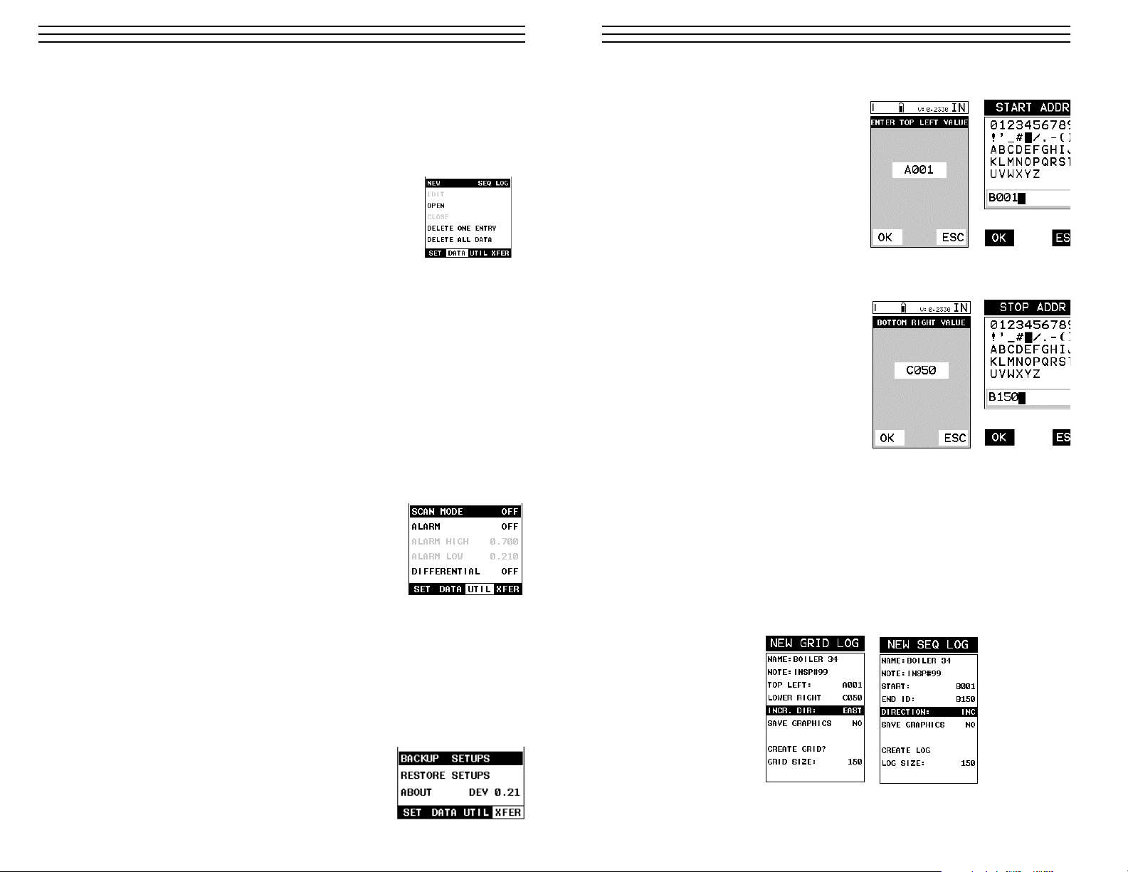
Setting the Coordinates or Start & Stop ID’s
Grid: A grid is defined by using coordinates to define the Top Left and the Bottom Right
corners of the grid. Alpha coordinates are horizontal across the top, and numeric coordinates are vertical down the side. Therefore, to define the top left corner of the grid, there
will be an (X,Y) coordinate. Where X is an alpha column location across the top and Y is a
numeric row location down the side. Use the same logic when choosing the lower right
corner. An individual grid can be up to 999 rows and 52 columns.
Sequential: The sequential file format can be viewed as a file as a single column of up to
512 possible rows (readings), and a column of corresponding identifiers associated with
each individual reading. The identifier can be a combination of up to 10 numeric, alpha, or
special characters listed above, while the file name can consist of a combination of up to 20
of the same character set.
Note: The identifier cannot start or end with a special character. Once a start and end ID
are entered into the TI-CMXDL and the log created, the TI-CMXDL will automatically
generate all the identifiers within that range.
Setting the Top Left(Grid) or Start ID(Seq)
1. Use the UP and DOWN arrow keys
to scroll through the new Grid or Seq
List Items until TOP LEFT or
START ID is highlighted.
2. Press the ENTER key to activate the
Coordinate or Start ID Edit Box.
3. GRID LOG: Use the LEFT, &
RIGHT arrow keys to scroll the
Columns, and the UP, DOWN arrow
keys to scroll the Rows.
SEQ LOG: Use the UP, DOWN,
LEFT, & RIGHT arrow keys to
highlight the appropriate alpha
characters. Press the ENTER key to select a character and advance to the next
character field, in conjunction with using the CLR key to backspace if necessary.
4. Press the OK key to select the coordinate or start ID and return to the Grid or Seq List
Items screen, or ESC to cancel the selection and return to the Grid or Seq List Items
menu.
-52-
Grid Log
Sequential Log
Page 18

3.18 Top & Bottom End Caps
The top & bottom end panels are where all connections are made to the TI-CMXDL. The
diagram above shows the layout and description of the connectors:
Transducer Connectors
Refer to Diagram: The transducer connectors, and battery cover/probe zero disk are located
on the TI-CMXDL’s top end cap. The transducer connectors are of type Lemo “00”.
NOTE: There is no polarity associated with connecting the transducer to the TI-CMXDL.
Probe Zero Disk & Battery Cover
Refer to Diagram: The Battery cover is the large round disk shown in the diagram. Note:
This same disk is also used as a probe zero disk. Simply remove the cover when replacing
the batteries (3 AA cells). When performing a manual probe zero function, simply place the
transducer on disk making firm contact.
IMPORTANT: Be sure to follow the polarity labels located on the back label of the
TI-CMXDL.
NOTE: Rechargeable batteries can be used, however they must be recharged outside of the
unit in a stand alone battery charger.
RS-232 Connector
Refer to Diagram: The RS-232 connector, located on the bottom end cap, is a 2 pin
female Lemo connector. It is designed to connect directly from the TI-CMXDL to a
standard AT serial port on a PC. The cable supplied with the TI-CMXDL is a Lemo to
9 pin serial cable. Note: This connector is also used to upgrade the TI-CMXDL with the
latest version of firmware.
USB Serial to USB Converter Cable
A converter cable can be attached to the 9 pin serial cable in needed (part no. N-402-0510).
-18-
4. Press the ENTER key to display the new Grid or Seq Edit Box.
5. Use the UP and DOWN arrow keys to scroll through the new Grid or Seq List Items
until NAME is highlighted.
6. Press the ENTER key to activate the Alpha Edit Box.
7. Use the UP, DOWN, LEFT, & RIGHT arrow keys to
highlight the appropriate alpha characters.
8. Press the ENTER key to select a character and
advance to the next field of the Grid or Seq Name.
9. Use the CLR key to backspace if necessary.
10. Repeat steps 6 – 9 until the Grid or Seq Name
(File Name) is completed.
11. Press the OK key to save the Grid or Seq Name and return to the Grid or Seq List
Items menu, or ESC to cancel entering the Grid or Seq Name (File Name).
Creating A Note
Grid/Seq Log Note: Can contain a
combination of up to 20 numeric,
alpha, or special characters listed in
the first section of this chapter.
1. Assuming the Grid or Seq List
Items are displayed, use the UP
and DOWN arrow keys to scroll
through the new Grid or Seq List
Items until NOTE is highlighted.
2. Press the ENTER key to activate the Alpha Edit Box.
3. Use the UP, DOWN, LEFT, & RIGHT arrow keys to highlight
the appropriate alpha characters.
4. Press the ENTER key to select a character and advance to the
next field of the Grid or Seq Note.
5. Use the CLR key to backspace if necessary.
-51-
Grid Log
Sequential Log
Grid Log
Sequential Log
Page 19

4.0 PRINCIPLES OF ULTRASONIC MEASUREMENT
4.1 Time versus thickness relationship
Ultrasonic thickness measurements depend on measuring the length of time it takes for
sound to travel through the material being tested. The ratio of the thickness versus the ti
is known as the sound velocity. In order to make accurate measurements, a sound veloci
must be determined and entered into the instrument.
The accuracy of a thickness measurement therefore depends on having a consistent soun
velocity. Some materials are not as consistent as others and accuracy will be marginal. F
example, some cast materials are very granular and porous and as a result have inconsist
sound velocities.
While there are many different ultrasonic techniques to measure thickness, which will b
discussed below, all of them rely on using the sound velocity to convert from time to thi
ness.
4.2 Suitability of materials
Ultrasonic thickness measurements rely on passing a sound wave through the material
being measured. Not all materials are good at transmitting sound. Ultrasonic thickness
measurement is practical in a wide variety of materials including metals, plastics, and
glass. Materials that are difficult include some cast materials, concrete, wood, fiberglass
and some rubber.
4.3 Range of measurement and accuracy
The overall measurement capabilities, based on the wide variety of materials, is determi
by the consistency of the material being measured
The range of thickness that can be measured ultrasonically depends on the material as w
as the technique being used and the type of transducer. Thickness measurements can be
made from a minimum of 0.010 inch to 9.999” in steel. However, the maximum attainab
thickness is much less for more attenuative materials (materials that absorb sound).
Accuracy, is determined by how consistent the sound velocity is through the sound path
being measured, and is a function of the overall thickness of the material. For example,
velocity in steel is typically within 0.5% while the velocity in cast iron can vary by 4%.
4.4 Couplant
All ultrasonic applications require some medium to couple the sound from the transduce
to the test piece. Typically a high viscosity liquid is used as the medium. The sound frequencies used in ultrasonic thickness measurement do not travel through air efficiently. B
using a liquid couplant between the transducer and test piece the amount of ultrasound
entering the test piece is much greater.
4.5 Temperature
Temperature has an effect on sound velocity. The higher the temperature, the slower sou
travels in a material. High temperatures can also damage transducers and present a prob
for various liquid couplants.
Since the sound velocity varies with temperature it is important to calibrate at the same
temperature as the material being measured.
-19-
Important Note: For the duration of this chapter, all references to GRIDS and SEQ
LOGS should be considered synonymous with references to FILES.
11.2 Creating a new Grid or Sequential Log (File)
Important Note: This entire section is a step by step guide to successfully create a grid or
sequential log. The instructions must be used in the sequential order specified, as follows:
Creating a Name
Grid/Seq Log Name: Can contain a combination of up to 20 numeric, alpha, or special
characters listed in the first section of this chapter.
1. Press the MENU key once to activate the menu items tab. Press the MENU key multiple
times to tab right, and the ESC key multiple times to tab left, until the DATA menu is
highlighted and displaying the submenu items.
2. Use the UP and DOWN arrow keys to scroll through the sub menu items until NEW is
highlighted.
3. Press the LEFT & RIGHT arrow keys to toggle the data formats – GRIG LOG &
SEQ LOG.
-50-
Sequential Log Formats
Grid Log
Sequential Log
Page 20

Normal temperature range
Most standard transducers will operate from 0∞F to 180∞F.
High temperature measurements
Special transducers and couplants are available for temperatures above 180∞F up to 650∞F
with intermittent contact. It is necessary to cool the transducer, by submerging the transducer in water between readings, when measuring high temperatures.
Modes and temperature errors
In addition to errors caused by velocity changing with temperature, some modes
(measurement techniques) are affected more than others. For example, dual element mode
has larger errors due to changes in temperature of the delay line. However, in multi-echo
techniques, auto temperature helps to minimize these errors.
4.6 Measurement Modes
In this section we will discuss the different measurements modes the TI-CMXDL is
capable of operating in, the transducers required, and the reasons for using specific modes:
Pulse-Echo Mode (Flaw & Pit detection) – Coating Off (P-E)
Pulse-echo mode measures from the initial pulse (sometimes referred to as an artificial
zero) to the first echo (reflection). In this mode, either an automatic or manual zero can be
performed depending on the zero probe function setting. If the manual mode has been
selected, the transducer is placed on a reference disk, located on top of the TI-CMXDL,
and a key is pressed to establish a zero point for the particular transducer. If the Auto Zero
feature is enabled, a simple key press will perform an electronic zero to establish the same
zero point.
In this mode errors result from surface coatings and temperature variations.
Since pulse-echo only requires one reflection, it is the most sensitive mode for measuring
weak reflections (flaws) typically found when measuring heavily corroded metals.
V-Path Correction
Dual element delay line transducers have two piezoelectric elements
mounted at an angle on one end of the delay line. One element is used
for transmitting sound, while the other element only receives sound.
The two elements and their delay lines are packaged in a single housing
but acoustically isolated from each other with a sound barrier. This
allows the transducer the ability to achieve very high sensitivity for
detecting small defects. Also, the surface of the test material does not
have to be as flat in order to obtain good measurements.
Dual element transducers are normally used in pulse-echo mode for
finding defects, and in echo-echo mode for through coating measurements.
Dual element delay line transducers are usable over a range of 0.025 inches to 20 inches
depending on the material, frequency, and diameter.
A limitation of dual element delay-line transducers is the V shaped sound path. Because the
sound travels from one element to another, the time versus thickness relationship is nonlinear. Therefore, a correction table in the instruments software is used to compensate for
this error.
-20-
Dual Element
Transducer
showing
V-path of signal
Important Note: For the duration of this chapter, all references to GRIDS and SEQ
LOGS should be considered synonymous with references to FILES.
11.2 Creating a new Grid or Sequential Log (File)
Important Note: This entire section is a step by step guide to successfully create a grid
sequential log. The instructions must be used in the sequential order specified, as follow
Creating a Name
Grid/Seq Log Name: Can contain a combination of up to 20 numeric, alpha, or special
characters listed in the first section of this chapter.
1. Press the MENU key once to activate the menu items tab. Press the MENU key multi
times to tab right, and the ESC key multiple times to tab left, until the DATA menu i
highlighted and displaying the submenu items.
2. Use the UP and DOWN arrow keys to scroll through the sub menu items until NEW
highlighted.
3. Press the LEFT & RIGHT arrow keys to toggle the data formats – GRIG LOG &
SEQ LOG.
-49-
Sequential Log Formats
Grid Log
Sequential Log
Page 21

-21-
Searching for small defects
Dual element delay line transducers are especially useful in searching for small defects.
the pulse-echo mode with high amplifier gain, very small defects can be measured. This
very useful during corrosion inspections overall. The dual element style transducer will
find wall deterioration, pits, and any porosity pockets during tank and pipeline inspectio
Echo-Echo Mode – Thru-Paint (E-E)
The echo-echo mode measures between two reflections. This technique
is commonly used to eliminate errors from surface coatings and also to
make measurements in multiple layered materials. The disadvantage is
that two echoes are needed which requires a much stronger echo
(reflection).
Echo-Echo Verify Mode – Thru-Verify (E-EV)
The echo-echo verify mode measures between 3 reflections. Similar to
E-E mode, this technique is commonly used to eliminate errors from
surface coatings and also to make measurements in multiple layered
materials. The primary benefit of this mode, is that a comparison is
made, between the 2nd and 3rd echoes, to verify that a peak jump
has not occurred, providing an additional level of confidence to the
measurement. The disadvantage is that 3 reflections are needed which
requires the use of gates with controllable thresholds to adjust for
sensitivity over a given measurement range.
Pulse Echo Coating Mode – Coating On (PECT)
A custom hybrid combination mode using properties from the basic modes along with a
group of special techniques and theoretical wave phenomena’s to measure coating and
material thicknesses at the same time, while still retaining the ability to locate flaws and
pits in materials. Therefore, the best description for this hybrid mode is Pulse-Echo Coa
mode.
Coating Mode – Coating Only (CT)
Once again, this is a custom hybrid combination mode using special techniques to effectively measure the thickness of coatings that are either adhered to metallic surfaces or in
stand alone form. In this mode a two point calibration must be performed. If the user wi
be measuring coating that has been applied to a metal surface, the calibration must be
performed using coating samples coupled to a metal surface when calibrating. To explai
further, a drop of couplant must be applied in between the coating samples and metal
surface. If the coating has not been applied to a metal surface, the calibration should be
performed accordingly.
Pulse-Echo Temperature Compensated Mode – Temp Comp (PETP)
This is a custom mode that combines pulse-echo and electronic zero techniques to
automatically adjust for temperature changes in the transducer as a result of an
increasing/decreasing temperature gradient in the test material.
NOTE: Rough surface conditions can have an effect on the overall accuracy in this mod
If the surface condition is in question, the pulse-echo mode should be used in conjunctio
with performing an off block automatic zero as the temperature gradient changes.
Dual Element
Transducer in
Echo to Echo
Verify mode
Dual Element
Transducer in
Echo to Echo
mode
11.0 DATA STORAGE – SETUP, EDIT, & VIEW FILES
11.1 Introduction to Grid and Sequential file formats
The TI-CMXDL is equipped with two data file format options, GRID LOG and SEQ LOG.
The GRID file format is very similar to a spreadsheet format found in popular software
programs like Excel. A GRID is simply a table of readings. A location in a grid is specified by giving a row and column coordinate. The rows are numbered from 1 to 999 and the
columns are labeled from A to ZZ (999 Rows & 52 Columns). The sequential file format
can be viewed as a file as a single column of up to 512 possible rows (readings), and a column of corresponding identifiers associated with each individual reading. The identifier can
be a combination of up to 10 numeric, alpha, or special characters listed above, while the
file name can consist of a combination of up to 20 of the same character set.
NOTE: The identifier cannot start or end with a special character. Once a start and end ID
are entered into the TI-CMXDL and the log created, the TI-CMXDL will automatically
generate all the identifiers within that range.
The following character set listed below are all the allowable characters that will be used
for both file formats: GRID & SEQ LOG. Any combination of these characters can be used
for creating a Name and Note regardless of the selected format.The allowable characters
are as follows:
Numeric characters: 0 – 9 Alpha Characters: A – Z
Special Characters: ! ‘ _ # space / . – ( )
Multiple grids can be created and stored until the TI-CMXDL’s memory is full. If the user
attempts to store a new file in the TI-CMXDL and the size of the file exceeds the capacity
of memory, the TI-CMXDL will respond with an error message indicating that the memory
is unable to store the new file.
The TI-CMXDL can store a total of 16,000+ readings with a corresponding screenshot of
the DIGITS or B-SCAN views with every reading, as well as all the TI-CMXDL settings
for every individual reading. If the graphics option is disabled, not saving screenshots, the
TI-CMXDL can store a total of 210,000+ readings. The screenshot stored with the reading
will depend on what view the TI-CMXDL was in at the time it was saved. For example, if
the view was in B-SCAN, then a B-SCAN will be saved with the reading.
In the sections that follow, the procedures for creating, using, and editing GRID’s and SEQ
LOG’s have been combined together for the purpose of similarity in overall functionality
and structure. The illustrations that follow are snapshots of typical GRID and SEQ LOG
file formats:
-48-
Grid File Formats
Page 22

5.0 SELECTING THE MEASUREMENT MODE
5.1 The setup library
The TI-CMXDL contains 64 user configurable preset locations to store custom setups for
easy recall. These setups can be optimized for the user’s specific application needs and can
also be stored on a PC and transferred bi-directionally using Dakota’s PC interface software included with the instrument.
5.2 Which mode & transducer do I use for my application?
High penetration plastics and castings
The most common mode for these types of applications is pulse-echo. The TI-CMXDL has
been optimized for cast materials. Cast iron applications require 1 - 5MHz frequencies, and
cast aluminum requires a 10MHz frequency. Plastics typically require lower frequencies
depending on the thickness and make-up of the material. Larger diameters offer greater
penetration power because of the crystal size, for difficult to measure materials.
Corrosion & Pit Detection in steel and cast materials
Use pulse-echo mode whenever attempting to locate pits and flaws. Typically a 5MHz
transducer, or higher, will be used for these types of applications. Use low frequencies for
greater penetration and use higher frequencies for better resolution.
Measuring Material & Coatings
The pulse-echo coating mode should be used when both material and coating thickness are
required, while still requiring the ability to detect flaws and pits. A special coating style
transducer is required for use in this mode. There are a variety of coating transducers in
various frequencies available from Electromatic.
Thru Paint & Coatings
Often times, users will be faced with applications where the material will be coated with
paint or some other type of epoxy material. Since the velocity of the coating is approximately 2.5 times slower than that of steel, pulse-echo mode will induce error if the coating
or paint is not completely removed. By using echo-echo mode, the user is able to successfully measure through both, the coating and steel, and completely eliminate the thickness
of the paint or coating. Therefore, the steel can be measured without having to remove the
coating prior to measuring. Users will often use pulse-echo mode and echo-echo mode in
conjunction when performing inspections on coated materials.
Thru coating measurements require special high damped transducers. The most common
transducers are the 3.5, 5, and 7.5MHz hi damped transducers. These transducers are
suitable for use in both pulse-echo and echo-echo modes. This conveniently enables the
user to accurately measure overall material thickness using the thru Coating mode, and
then conveniently switch to pit detection mode without changing transducers. The _”
5MHz Hi damped transducer is the most commonly used transducer for standard thru
coating applications.
-22-
3. Press the LEFT and RIGHT arrow keys to scroll the digit locations.
4. Repeat steps 2 & 3 until the DIFFERENTIAL value is correctly displayed.
5. Press the OK key to set the DIFFERENTIAL value and return to the menu screen.
6. Finally, press the MEAS key to return to the measurement screen and begin
taking readings.
-47-
Page 23

Coating Only
The coating only mode should be used when the application calls for coating measurements only and the user is not interested in the thickness of the material the coating has
been applied to. This mode can also be used as a stand alone coating thickness gauge,
where the coating has not been applied to another material surface. An auto identified
coating probe must be attached to the TI-CMXDL in order to enable this mode.
Thin materials
Use pulse echo mode and a high frequency transducer for these types of applications. Th
most common transducers are the 7.5MHz and 10MHz models with extra resolution. Th
higher frequencies provide greater resolution and a lower minimum thickness rating
overall.
High temperature
Use and select a special 2.25MHz and 5 MHz High temperature transducer for these
types of applications. Both pulse-echo and echo-echo modes will also work for these
applications. However, echo-echo mode will eliminate error caused by temperature
variations in the delay line of the transducer.
Noisy Material
Materials such as titanium, stainless steel, and aluminum may have inherent surface nois
issues. This is a signal that appears at the surface of the material when using a dual elem
delay line probe. Select a higher frequency transducer to reduce this noise – 7.5MHz an
higher for better resolution.
Restricted access
Measuring materials with extreme curvatures or restricted access, higher frequencies wit
smaller diameters should be considered. The smallest diameter uses 3/16” crystals with
contact area of .250”. Custom transducers are available on request.
5.3 Factory Setup Chart
There are no standard factory setups provided with the TI-CMXDL, as the primary reaso
for the setups is to retain all of the user adjustments made to set the gauge for use on a s
cific application. Saving a setup allows you to retain all of the settings made to tune the
gauge, such as Gain setting, 1 or 2 Point Calibration values for the Material and/or the
Coating, Acoustic Velocity setting, Alarm limits, operating mode, B-scan settings and
much, much more. Refer to section 11.0 for additional info on Setups.
-23-
Setting the Alarm Low Limit
1. Assuming the ALARM is ON, use the UP and DOWN arrow
keys to scroll through the sub menu items until ALARM LOW
is highlighted.
2. Press the LEFT and RIGHT arrow keys to scroll the value.
When the correct alarm value is being displayed, proceed to
step 7.
3. Alternatively, press the ENTER key to display the Digits Edit
Box.
4. Press the UP and DOWN arrow keys to scroll the highlighted
value.
5. Press the LEFT and RIGHT arrow keys to scroll the digit
locations.
6. Repeat steps 4 & 5 until the ALARM LOW value is correctly
displayed.
7. If only one limit will be used, press the MEAS key to return to
the measurement screen and begin taking readings. Otherwise,
continue on to set the ALARM HIGH limit.
10.3 Differential Mode
The Differential Mode of the TI-CMXDL provides the user with the ability to set a nominal value, according to what the expected thickness should be, and measure the +/- difference from the nominal value entered. This feature is typically used in QA incoming inspections on pipes, plate stock, coils, etc. The steps below outline how to enable and enter the
nominal value to use this feature:
Toggle Differential (on/off)
1. Press the MENU key once to activate the menu items tab.
Press the MENU key multiple times to tab right, and the
ESC key multiple times to tab left, until the UTIL menu is
highlighted and displaying the submenu items.
2. Use the UP and DOWN arrow keys to scroll through the
sub menu items until DIFFERENTIAL is highlighted.
3. Use the LEFT and RIGHT arrow keys to toggle the
DIFFERENTIAL on. A value will appear to the right of
DIFFERENTIAL.
4. Continue on to the next section “Setting the Differential Value”.
Setting the Differential Value
1. Assuming DIFFERENTIAL has been enabled and a value is
being displayed to the right of the DIFFERENTIAL label,
press the ENTER key to display the Digits Edit Box.
2. Press the UP and DOWN arrow keys to scroll the highlighted
value.
-46-
Page 24

-24-
Material sound velocity sound velocity
in/us m/s
Aluminum 0.2510 6375
Beryllium 0.5080 12903
Brass 0.1730 4394
Bronze 0.1390 3531
Cadmium 0.1090 2769
Columbium 0.1940 4928
Copper 0.1830 4648
Glass (plate) 0.2270 5766
Glycerine 0.0760 1930
Gold 0.1280 3251
Inconel 0.2290 5817
Iron 0.2320 5893
Cast Iron 0.1800 (approx) 4572
Lead 0.0850 2159
Magnesium 0.2300 5842
Mercury 0.0570 1448
Molybdenum 0.2460 6248
Monel 0.2110 5359
Nickel 0.2220 5639
Nylon 0.1060 (approx) 2692
Platinum 0.1560 3962
Plexiglas 0.1060 2692
Polystyrene 0.0920 2337
PVC 0.0940 2388
Quartz glass 0.2260 5740
Rubber vulcanized 0.0910 2311
Silver 0.1420 3607
Steel (1020) 0.2320 5893
Steel (4340) 0.2330 5918
Steel Stainless" 0.2230 5664
Teflon 0.0540 1372
Tin 0.1310 3327
Titanium 0.2400 6096
Tungsten 0.2040 5182
Uranium 0.1330 3378
Water 0.0580 1473
Zinc 0.1660 4216
Zirconium 0.1830 4648
Acoustic Velocity Table
10.0 ADDITIONAL FEATURES OF THE TI-CMXDL
10.1 High Speed Scan
The High Speed Scan feature of the TI-CMXDL increases the overall repetition rate to a
maximum of 140Hz with a high speed screen refresh rate of 25 times a second. This
feature enables a user to make scanned passes over an arbitrary length of the test materi
while still maintaining a reasonable representation of thickness over the scanned area or
region. This feature can be used in conjunction with High and Low alarm limits features
to dynamically keep track of both values. The feature is typically used to provide a bette
representation of the area scanned, by taking more readings at a faster rate repetition rat
The procedure to use the SCAN MODE feature is outlined below:
Using the Scan Mode
1. Press the MENU key once to activate the menu items tab.
Press the MENU key multiple times to tab right and the ESC
key multiple times to tab left until the UTIL menu is highlighted
and displaying the submenu items.
2. Use the UP and DOWN arrow keys to scroll through the sub
menu items until SCAN MODE is highlighted.
3. Use the LEFT and RIGHT arrow keys to toggle the
SCAN MODE on/off.
4. Press the MEAS key to return to the measurement screen.
10.2 Alarm Mode
The Alarm Mode feature of the TI-CMXDL provides the user with a method of setting t
erances, or limits, for a particular application requirement. This feature may be used for
variety of applications to verify the material is within the manufacturer specifications.
There are two limits, or alarm values, that can be setup in the TI-CMXDL – ALARM LO
and ALARM HIGH limits. However, the user may choose to activate and utilize only on
of the limit values, depending on their specific application requirements. The procedures
use the ALARM MODE feature are outlined below:
Toggle Alarm (on/off)
1. Press the MENU key once to activate the menu items tab.
Press the MENU key multiple times to tab right, and the
ESC key multiple times to tab left, until the UTIL menu is
highlighted and displaying the submenu items.
2. Use the UP and DOWN arrow keys to scroll through the
sub menu items until ALARM is highlighted.
3. Use the LEFT and RIGHT arrow keys to toggle the
ALARM on/off/audible.
4. Continue on to the next section “Setting the Alarm Low
Limi.t."
-45-
Page 25

6.0 TAKING MEASUREMENTS
The steps involved in making measurements are detailed in this section. The following section
outline how to setup and prepare your TI-CMXDL for field use.
An automatic or manual zero must always be performed. The auto zero is an off block electron
zero that does not require a zero reference block. This will most always be the zero option of
choice, as it makes the zeroing process very easy and convenient to perform. However, If the
manual zero option is enabled, the probe zero must be measured on the reference disk (battery
disk) attached to the top of the instrument. The zero compensates for variations in the transduc
In all modes the sound velocity must be determined. The sound velocity is used to convert the
transit time to a physical length. The sound velocity can be selected from a material chart in th
manual, selected from a material list in the TI-CMXDL, or for greater precision determined fro
a sample of the test material that has been mechanically measured. To enter the velocity from a
table, look up the material on the chart in the appendix of this manual and refer to the section
below on Calibration to a Known Velocity. To determine the velocity of a single sample, refer
the Material Calibration section 6.0
When measuring curved materials, it is more accurate to calibrate from two test points, one at
minimum limit of the target thickness and one at the maximum limit. In this case the reference
disk mounted to the TI-CMXDL is not used. This is called two-point calibration and is describ
on section 6.0.
6.1 Auto Probe Recognition & Selecting The Transducer Type
The first step in using the TI-CMXDL is to plug the transducer into the gauge and powe
the unit up. The TI-CMXDL has a special built-in automatic probe recognition feature th
will check to see if the probe plugged into the gauge is an auto recognized probe type. I
so, the TI-CMXDL will display a message indicating the transducer type and ask the use
for confirmation to use the identified probe. If the transducer is not an auto recognized
probe, the TI-CMXDL will display a message indicating the transducer type has not bee
recognized, and force the user to select a transducer type from a list of transducers accor
ing to frequency and diameter. Whether the transducer is auto recognized or selected fro
a predefined list, the TI-CMXDL will recall specific properties about the transducer.
NOTE: Once the transducer has been selected, the TI-CMXDL will store and recall this
transducer type every time the TI-CMXDL is powered on/off. The type will only change
the user physically selects another type from the list, or selects a previously saved setup
Therefore, if you have previously gone through this section and selected the transducer y
are using, proceed to the next section. Use the following steps to select your transducer ty
NOTE: If the transducer is not identified on power up, be sure the transducer type
Selected is the same as the transducer plugged into the TI-CMXDL. Failure to do this w
result in erroneous measurements:
In this first example the transducer was automatically identified:
1. Press the OK key once to use the identified probe, or ESC
to display a list of optional transducers.
NOTE: If the TI-CMXDL recognizes a specific transducer, the
user should always select OK to use the identified probe. The
only time an alternative probe should be selected from a list
is if the user switched probes following initial power up and
recognition, or the TI-CMXDL has somehow identified the
probe in error..
-25-
2. Apply a drop of couplant on the transducer and place the transducer in steady contact
with the thinner of the two coating and samples. Be sure that the reading is stable and
the repeatability indicator, in the top left corner of the display, is fully lit and stable.
Press the MENU key once to activate the menu items tab. Press the MENU key multiple
times to tab right and the ESC key multiple times to tab left until the CAL menu is
highlighted and displaying the submenu items.
3. Use the UP and DOWN arrow keys to scroll through the sub
menu items until COATING 2PT is highlighted.
4. Press the ENTER key to display the Digits Edit Box.
5. Press the UP and DOWN arrow keys to scroll the highlighted
value.
6. Press the LEFT and RIGHT arrow keys to scroll the digit
locations.
7. Repeat steps 5 & 6 until the known thickness value is correctly
displayed.
8. Press the OK key to calculate the velocity and return to the menu screen,
or ESC to cancel the coating one point calibration.
9. Finally, press the MEAS key to return to the measurement screen and begin taking
readings.
NOTE: CHECK YOUR CALIBRATION! Place the transducer back on both calibration
points. The coating thickness readings should now match the known thickness values of
each sample. If the thickness is not correct, repeat the steps above.
-44-
Page 26

2. Assuming the TI-CMXDL recognized the probe and the OK
key was pressed, the TI-CMXDL will advance to a Zero Probe
menu. If the transducer was identified as a special transducer
capable of measuring coating thickness, a menu will be
displayed allowing the user the ability to toggle the coating
thickness display on/off as follows:
3. Press the UP and DOWN arrow keys to toggle the coating
option on/off.
4. Wipe all couplant from the transducer face and proceed to the
Probe Zero section that follows.
In this second example the transducer was not identified and will force the user to select
the transducer type from a predefined list of transducers:
1. Press the OK or ESC keys to display the factory list of
transducer types (by diameter and frequency).
2. Press the UP and DOWN arrow keys to scroll through the
transducer list until the appropriate type is highlighted.
3. Press the ENTER key to select the transducer type and
display overwrite existing probe screen.
4. Press the OK key to overwrite the existing probe type with
the newly selected probe type. The zero probe screen will be
displayed. Proceed to the zero probe section that follows.
6.2 Probe zero
The next step is to perform a probe zero. The zero function is
a very important and necessary function that must be done prior
to calibration. It should be done on a regular basis. In fact, the
TI-CMXDL has been programmed to force this issue at regular
intervals during operation if it hasn’t been done. If the TICMXDL is not zeroed correctly, all the measurements taken may
be in error by some fixed value. When the TI-CMXDL is using
the auto zero (electronic zero), the TI-CMXº can be in any measurement mode. However, when the manual zero is being used, the TI-CMXDL must be in
pulse-echo mode in order to perform the zero. The TI-CMXDL will also see to it that this
occurs bysimply forcing the gauge into this mode when zero. Therefore, if the TI-CMXDL
is in the echo-echo measurement mode and a manual zero is being performed, the TICMXDL will put the gauge into pulse-echo mode automatically before performing the
zero. While this is a very convenient feature of the TI-CMXDL, the user should be sure to
check the measurement mode following calibration to be sure the TI-CMXDL is in the
desired mode. The following steps outline both of these techniques.
The TI-CMXDL is equipped with two zero options:
1. Off Block Zero (Automatic Probe Zero) – When this feature is enabled the
TI-CMXDL will do an electronic zero automatically, eliminating the need for a zero
disk or block.
2. On Block Zero (Manual Probe Zero) – When this feature is enabled the transducer
must be placed on the probe zero disk (battery cover located on the top of the unit.
Both zero procedures are outlined as follows
-26-
One Point Calibration
NOTE: Use the maximum coating sample for the one point calibration first.
1. Physically measure the thicker of the two samples of coating, as close as possible to
maximum expected coating measurement range, using a set of calipers or a digital
micrometer.
Very Important: If coating measurements will be made with the coating applied to a
metal surface, the calibration must be done in the same manner, with the samples couple
to a metal surface. However, if the coating will be measured as a stand alone material, th
calibration must be performed the same way.
2 Apply a drop of couplant on the transducer and place the transducer in steady contac
with the thicker of the two coating and samples fist. Be sure that the reading is stable
and the repeatability indicator, in the top left corner of the display, is fully lit and stab
Press the MENU key once to activate the menu items tab. Press the MENU key multi
times to tab right and the ESC key multiple times to tab left until the CAL menu is
highlighted and displaying the submenu items.
3. Use the UP and DOWN arrow keys to scroll through the sub
menu items until COATING 1PT is highlighted.
4. Press the ENTER key to display the Digits Edit Box.
5. Press the UP and DOWN arrow keys to scroll the highlighted
value.
6. Press the LEFT and RIGHT arrow keys to scroll the digit
locations.
7. Repeat steps 5 & 6 until the known thickness value is correctly
displayed.
8. Press the OK key to calculate the velocity and return to the menu screen, or ESC to
cancel the coating one point calibration.
9. Finally, press the MEAS key to return to the measurement screen and begin taking
readings.
Two Point Calibration
NOTE: Use the minimum coating sample for the two point calibration.
1. Physically measure the thinnest of the two samples of the
coating, as close as possible to the minimum expected coating
measurement range, using a set of calipers or a digital
micrometer.
Very Important: If coating measurements will be made with the
coating applied to a metal surface, the calibration must be done in
the same manner, with the samples coupled to a metal surface.
However, if the coating will be measured as a stand alone material,
the calibration must be performed the same way.
-43-
Page 27

Performing an Auto Probe Zero (Off Block)
1. Be sure all couplant has been
removed from the face of the
transducer.
2. Press the OK key to perform the
automatic probe zero, or ESC key
to cancel the zero operation.
3. The screens illustrated at right will
be briefly displayed followed by the
main measurement screen. The
CMX is ready to be calibrated.
Performing a Manual Probe Zero (On Block)
NOTE: When the zero probe option is set to manual, the probe zero disk (battery cap)
located on the top of the gauge will be used as a zero standard and the warning screen
illustrated above will be displayed.
1. Press the OK or ESC keys to enter the main measurement screen and begin the manu
zero process.
2. Apply a drop of couplant on the transducer and place the transducer in steady contac
with the probe zero disk and obtain a steady reading.
3. Press the MENU key once to activate
the menu items tab. Press the MENU
key multiple times to tab right and the
ESC key multiple times to tab left
until the PRB menu is highlighted
and displaying the submenu items.
4. Press the UP and DOWN arrow keys
to scroll through the sub menu items
until ZERO PROBE is highlighted.
5. Press the ENTER key to display the
confirmation screen.
6. If a coating transducer was identified
use the UP and DOWN arrow keys to
toggle coating on/off.
-27-
Coating Probe
Identified
Coating Probe
Not Identified
Coating Probe
Identified
Coating Probe
Not Identified
Coating Probe
Identified
Coating Probe
Not Identified
2. Apply a drop of couplant on a piece of metal and place the coating sample on the metal
over the couplant. Apply a drop of couplant on the transducer and place the transducer
in steady contact with the coating and sample or actual test material. Be sure that the
reading is stable and the repeatability indicator, in the top left corner of the display, is
fully lit and stable. Press the MENU key once to activate the menu items tab. Press the
MENU key multiple times to tab right and the ESC key multiple times to tab left until
the CAL menu is highlighted and displaying the submenu items.
3. Use the UP and DOWN arrow keys to scroll through the
sub menu items until COATING 1PT is highlighted.
4. Press the ENTER key to display the Digits Edit Box.
5. Press the UP and DOWN arrow keys to scroll the highlighted
value.
6. Press the LEFT and RIGHT arrow keys to scroll the digit
locations.
7. Repeat steps 5 & 6 until the known thickness value is correctly
displayed.
8. Press the OK key to calculate the velocity and return to the menu
screen, or ESC to cancel the coating one point calibration.
9. Finally, press the MEAS key to return to the measurement screen and begin taking
readings.
NOTE: CHECK YOUR CALIBRATION! Place the transducer back on the calibration
point. The coating thickness reading should now match the known thickness. If the
thickness is not correct, repeat the steps above.
9.4 Introduction to Coating Measurement (CT)
In the previous sections we’ve discussed how to setup and use the coating feature for use
in conjunction with material thickness and flaw and pit detection. The TI-CMXDL also has
the capability to be used for general coating measurements. This measurement mode is
called Coating (CT) and can be enabled using the same methods as described in a previous
section above.
When the Coating Only (CT) mode is enabled, a two point calibration on the coating
samples must be performed. This is to ensure linearity over the coating measurement range
will be achieved. Important note: If coating measurements will be made with the coating
applied to a metal surface, the calibration must be done in the same manner, with the
samples coupled to a metal surface. However, if the coating will be measured as a stand
alone material, the calibration must be performed the same way.
9.5 Two Point Coating Calibration (CT)
Known Thickness
The following section will demonstrate the two point coating calibration procedure. This
example demonstrates a coating thickness range of .040” - .120” ( 1 – 3 mm) as follows:
NOTE: It’s always handy to carry a set of mechanical calipers to use in conjunction with
the TI-CMXDL for calibration in the field:
-42-
Page 28
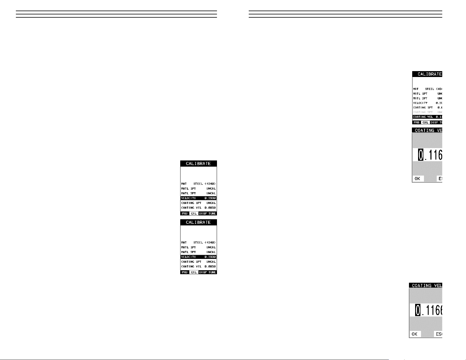
7. Press the OK key to complete the probe zero function, or ESC key to cancel the probe
zero function.
8. Remove the transducer from the probe zero disk, and proceed to the calibration section.
NOTE: The value that is displayed will change depending on the current velocity setting
in the TI-CMXDL. Disregard the number that is displayed. It is not important. What is
important is accurately performing the steps outlined above to insure reliability of the
probe zero
calculation.
6.3 Material Calibration
In order for the TI-CMXDL to make accurate measurements, it must be set to the correct
sound velocity of the material being measured. Different types of materials have different
inherent sound velocities. For example, the velocity of sound through steel is about 0.233
inches per microsecond, versus that of aluminum, which is about 0.248 inches per
microsecond. If the gauge is not set to the correct sound velocity, all of the measurements
the gauge makes will be erroneous by some fixed percentage.
The One Point calibration is the simplest and most commonly used calibration method—
optimizing linearity over large ranges. The Two Point calibration allows for greater
accuracy over small ranges by calculating the probe zero and velocity. The TI-CMXDL
provides four simple methods for setting the sound-velocity outlined below:
Using A Known Velocity
1. Press the MENU key once to activate the menu items tab. Press the
MENU key multiple times to tab right and the ESC key multiple
times to tab left until the CAL menu is highlighted and displaying
the submenu items.
2. Use the UP and DOWN arrow keys to scroll through the sub menu
items until VELOCITY is highlighted.
3. Press the ENTER key to display the Digits Edit Box.
4. Press the UP and DOWN arrow keys to scroll the highlighted value.
5. Press the LEFT and RIGHT arrow keys to scroll the digit locations.
6. Repeat steps 4 & 5 until the velocity number is correctly displayed.
7. Press the OK key to set the velocity and return to the menu screen,
or ESC to cancel entering the velocity.
8. Finally, press the MEAS key to return to the measurement screen
and begin taking readings.
Using A Known Thickness
Sometimes the sound velocity of a material is unknown. In this case a sample with one or
two known thicknesses can be used to determine the sound velocity. As previously discussed, the TI-CMXDL has a one or two point calibration option. The one point calibration
option is most suited for linearity over large ranges, as noted above. The user should also
consider calibrating on high side of the intended measurement range, when using the one
point option, minimize overall error. For example, if the measurement range is .100”
-28-
9.3 Coating Calibration (PECT)
Known Velocity
If the coating velocity is known, the user may wish to simply enter the velocity number
into the TI-CMXDL, rather than have the TI-CMXDL calculate the velocity value using
known thickness on a coating sample(s). The steps for entering the velocity are outlined
below:
Using a Known Material Velocity
1. Press the MENU key once to activate the menu items tab.
Press the MENU key multiple times to tab right and the ESC
key multiple times to tab left until the CAL menu is
highlighted and displaying the submenu items.
2. Use the UP and DOWN arrow keys to scroll through the sub
menu items until COATING VEL is highlighted.
3. Press the ENTER key to display the Digits Edit Box.
4. Press the UP and DOWN arrow keys to scroll the highlighted
value.
5. Press the LEFT and RIGHT arrow keys to scroll the digit
locations.
6. Repeat steps 4 & 5 until the velocity number is correctly
displayed.
7. Press the OK key to set the velocity and return to the menu
screen, or ESC to cancel entering the velocity.
8. Finally, press the MEAS key to return to the measurement screen and begin taking
readings.
Known Thickness
Sometimes the sound velocity of a coating material is unknown. In this case a sample w
a known thickness can be used to determine the sound velocity of the coating. As previo
ly discussed, the TI-CMXDL offers a one point calibration option for coating in PECT
measurement mode. It is also import to reiterate that the coating sample must be coupled
a metallic material in order to perform the calibration. The calibration should also consid
calibrating on high side of the intended measurement range, when using the one point
option, minimize overall error. For example, if the measurement range of the coating wi
be from .040” - .080” (1.0mm 2.3mm), a coating closest to .080 (2.0mm) should be used
NOTE: It’s always handy to carry a set of mechanical calipers to use in conjunction wit
the TI-CMXDL for calibration in the field:
One Point Calibration
NOTE: Be sure that the probe zero procedure has been performed
prior to performing this calibration procedure.
1. Physically measure an exact sample of the coating using a set
of calipers or a digital micrometer.
NOTE: The coating sample must be coupled to a metallic material
in order to be calibrated.
-41-
Page 29

(2.54mm) to 1.0” (25.4mm), the user should calibrate on a known thickness sample clos
to 1.0” (25.4mm).
NOTE: It’s always handy to carry a set of mechanical calipers to use in conjunction wit
the TI-CMXDL for calibration in the field:
One Point Calibration
NOTE: Be sure that the probe zero procedure has been performed prior to performing th
calibration procedure.
1. Physically measure an exact sample of the material or a
location directly on the material to be measured using a set
of calipers or a digital micrometer.
2. Apply a drop of couplant on the transducer and place the
transducer in steady contact with the sample or actual test
material. Be sure that the reading is stable and the repeatability
indicator, in the top left corner of the display, is fully lit and
stable. Press the MENU key once to activate the menu items tab.
Press the MENU key multiple times to tab right and the ESC
key multiple times to tab left until the CAL menu is highlighted
and displaying the submenu items.
3. Use the UP and DOWN arrow keys to scroll through the sub
menu items until MATL 1PT is highlighted.
4. Press the ENTER key to display the Digits Edit Box.
5. Press the UP and DOWN arrow keys to scroll the highlighted
value.
6. Press the LEFT and RIGHT arrow keys to scroll the digit
locations.
7. Repeat steps 5 & 6 until the known thickness value is correctly
displayed.
8. Press the OK key to calculate the velocity and return to the menu screen, or ESC to
cancel the one point calibration.
9. Finally, press the MEAS key to return to the measurement screen and begin taking
readings.
NOTE: CHECK YOUR CALIBRATION! Place the transducer back on the calibration
point. The thickness reading should now match the known thickness. If the thickness is
correct, repeat the steps above.
At some point there may become a requirement for improved accuracy over a smaller
measurement range. In this case, a two point calibration would be most suited for the job
For example, if the measurement range was .080” (2.03mm) to .250” (6.35mm), the use
would perform a one point calibration on a known thickness sample close to .250”
(6.35mm), followed by a two point calibration close to .080” (2.03mm). When a two po
calibration is performed, the TI-CMXDL calculates the zero and the velocity.
The following steps outline this procedure:
-29-
Probe Automatically Recognized (PECT only)
1. Press the OK key once to use the identified probe, or ESC to
display a list of optional transducers.
NOTE: If the TI-CMXDL recognizes a specific transducer, the user
should always select OK to use the identified probe. The only time
an alternative probe should be selected from a list is if the user
switched probes following initial power up and recognition.
2. Assuming the TI-CMXDL recognized the probe and the OK key
was pressed, the TI-CMXDL will advance to a Zero Probe menu.
If the transducer was identified as a special transducer capable of
measuring coating thickness, a menu will be displayed allowing
the user the ability to toggle the coating thickness display on/off
as follows:
3. Press the UP and DOWN arrow keys to toggle the coating
option on/off.
Multi Mode Key Pressed (PECT & CT)
1. Press the MULTI MODE key located
on bottom left of the keypad to display
the MEASURE MODE options menu.
2. Press the UP and DOWN arrow keys
to highlight the COATING ON (PECT)
or COATING ONLY (CT) menu option.
3. Press the ENTER key to enable the
coating option, or ESC to cancel
changing the measure mode, and
return to the main measurement screen.
Measure Mode (Tabbed Menus) – (PECT & CT)
1. Press the MENU key once to activate
the menu items tab. Press the MENU
key multiple times to tab right, and the
ESC key multiple times to tab left,
until the TUNE menu is highlighted
and displaying the submenu items.
2. Use the UP and DOWN arrow keys
to scroll through the sub menu items
until MEASURE MODE is highlighted.
3. Press the LEFT and RIGHT arrow
keys to scroll the modes.
4. When the correct MODE is being
displayed, press the MEAS key to
return to the measurement screen and
begin taking readings.
-40-
Applied to
Metals
Not Applied to
Metals
Applied to
Metals
Not Applied to
Metals
Page 30

Two Point Calibration
1. Physically measure an exact sample of the material or a location
directly on the material to be measured using a set of calipers or
a digital micrometer.
2. Apply a drop of couplant on the transducer and place the transducer in steady contact with the sample or actual test material.
Be sure that the reading is stable and the repeatability indicator,
in the top left corner of the display, is fully lit and stable. Press
the MENU key once to activate the menu items tab. Press the
MENU key multiple times to tab right and the ESC key
multiple times to tab left until the CAL menu is highlighted and
displaying the submenu items.
3. Use the UP and DOWN arrow keys to scroll through the sub
menu items until MATL 2PT is highlighted.
4. Press the ENTER key to display the Digits Edit Box.
5. Press the UP and DOWN arrow keys to scroll the highlighted
value.
6. Press the LEFT and RIGHT arrow keys to scroll the digit
locations.
7. Repeat steps 5 & 6 until the known thickness value is correctly
displayed.
8. Press the OK key to calculate the velocity and return to the menu screen, or ESC to
cancel the one point calibration.
9. Finally, press the MEAS key to return to the measurement screen and begin taking
readings.
NOTE: CHECK YOUR CALIBRATION! Place the transducer back on the calibration
point. The thickness reading should now match the known thickness. If the thickness is
correct, repeat the steps above.
Basic Material Type
If the material velocity is unknown, and a sample thickness cannot be taken from the ma
rial, the user may opt to choose a basic material type from a list with approximate veloc
values according to various material types. It’s important to note that these velocities wi
not always be an exact representation of the material being tested. Use these values only
a close approximation is acceptable. Follow the steps below to select a basic material typ
1. Press the MENU key once to activate the menu items tab.
Press the MENU key multiple times to tab right and the
ESC key multiple times to tab left until the CAL menu is
highlighted and displaying the submenu items.
2. Use the UP and DOWN arrow keys to scroll through
the sub menu items until MAT is highlighted.
-30-
9.0 PULSE-ECHO COATING & COATING TECHNIQUES
9.1 Introduction to Pulse-Echo Coating Measurement (PECT)
In the previous sections we’ve discussed the need for detecting pits and flaws (pulse-echo)
in materials, along with the requirement to measure through and eliminate errors caused by
coated materials (echo-echo). Until now, both modes were needed in order accomplish both
tasks. Pulse-echo mode was used for flaw detection, and echo-echo mode was used to eliminate the coating thickness and provide a nominal material thickness only. With this in
mind, it often became cumbersome toggling between both modes respectively.
In a majority of applications involving coated materials, inspectors are often interested in
monitoring both the thickness of the material, as well as the thickness of the coating.
Therefore, the TI-CMXDL has been designed to provide the user with the ability to measure the material and coating thicknesses simultaneously, while maintaining the ability to
detect flaws and pits all in a single mode called Pulse-Echo Coating (PECT). This is
accomplished by using a custom hybrid combination mode utilizing properties from the
basic modes along with a group of special techniques and theoretical wave phenomena’s.
The TI-CMXDL is preset to a coating velocity of 0.0850 in/µsec (2159 m/sec) from the
factory. This velocity is a very close approximation of the common coating velocities found
in the field. However, the TI-CMXDL also has a built-in one and two point calibration
options to calibrate to coating samples with a known thicknesses.
There are two coating modes built into the TI-CMXDL:
1. Pulse-Echo Coating (PECT) – used during inspections where both the material
and coating thicknesses are required.
2. Coating Only (CT) – used during inspections where only the coating thickness is
required.
9.2 Enabling Pulse-Echo Coating Mode (PECT) & Coating (CT)
When the TI-CMXDL is initially powered up, the gauge will automatically check to see if
the transducer plugged into the gauge can be recognized. All Dakota Ultrasonics coating
enabled transducers are equipped with the auto recognition feature. If the TI-CMXDL
doesn’t recognize that a special coating enabled transducer is plugged into the gauge, the
coating feature will be disabled entirely. There are a number of coating enabled transducers
available from Dakota. Please contact us with your application requirements for additional
information on frequencies and diameters currently offered.
The coating modes can be enabled in three different ways:
1. On Power up and probe recognition.
2. By pressing MULTI MODE keypad.
3. From the tabbed menus under TUNE, MEASURE MODE.
The steps that follow will demonstrate all three methods in the order listed above.
-39-
Page 31

3. Press the ENTER key to display the list of material types.
4. Press the UP and DOWN arrow keys to scroll through the
material list until the appropriate material is highlighted.
5. Press the ENTER key to overwrite the material type and
display the menu items with the new material type selected.
6. Finally, press the MEAS key to return to the measurement
screen and begin taking readings.
To calibrate the TI-CMXDL for a specific type of coating using
samples with known thicknesses, please refer to the chapter 9 –
Pulse-Echo Coating (PECT) or Coating (CT) for a complete explanation of using the TI-CMXDL for coating measurements.
-31-
8.0 THRU-PAINT MEASUREMENT TECHNIQUE
8.1 Introduction to Thru Paint Measurement
The principle behind thru paint measurement is by measuring the time between two backwall echoes returning from the test material. Since both of these backwall echoes travel the
same path through the paint or coating, the thickness of the coating is subtracted out of the
measurement so that only the actual material thickness can be measured. This feature saves
the user a great deal of time scraping and removing the coating from tanks and pipes during the inspection process.
The primary purpose of thru paint measurement is to determine actual or overall material
thickness by eliminating the coating thickness. Thru paint mode cannot be used for flaw
or pit detection. Therefore, inspectors may need to use echo-echo thru paint mode in conjunction with the standard pulse-echo flaw detection mode for some applications. Chassis
tubing inspectors and sanctioning bodies will use the echo-echo mode for tubing with
powder coatings, and pulse-echo mode for tubing without coating. The combination of
using both modes is ideal for the advanced inspectors needs.
8.2 Using Thru Paint Mode
The first thing to note in this section, is that by selecting the transducer type from the list
of probes stored in the TI-CMXDL, a basic echo-echo thru paint configuration is recalled
from memory. Each of the transducers in the list contains pre-configured echo-echo settings. The standard transducer that will be used for common steel applications _” 5MHz
high damped transducer (1/4IN – 5.0MHZ HD). This is the recommended transducer for
this industry and should be used for thru paint applications. Any of the auto recognition
coating transducers are also high damped transducers and will work in echo-echo mode as
well.
NOTE: When a transducer is selected for use, all of the measurement modes available for
use with this transducer can easily be determined by pressing the multi-mode button on
the keypad. The TI-CMXDL has been programmed to identify the modes available to a
specific transducer.
Once the transducer type has been selected and the appropriate calibration procedure
completed, the TI-CMXDL can toggle between pulse-echo (flaws & pits), and echo-echo
(thru paint) modes by simply pressing the MULTI MODE key located on the keypad.
Refer to section 6.0 for additional information.
The TI-CMXDL can also be configured for thru paint applications by selecting a factory
setup stored in the list of setups in the TI-CMXDL. Refer to section 12.0 for information
on recalling a setup. Once either the transducer type or setup has been selected, the
inspector is ready to begin making measurements.
-38-
Page 32

7.0 USING THE DIGITS AND B-SCAN DISPLAYS
A key feature of the TI-CMXDL is the ability to toggle between two different display options,
Digits and B-Scan. The Digits view provides the user with a large digital readout of the thickness.
Both views also include a scan bar features that uses a bar graph to indicate thickness. The
Scan bar can be very handy while scanning a tank or pipe wall by graphically displaying
deflections from pits or internal flaws, rather than having to constantly watch for changes in
the digital readout. It’s just another visual aid to alarm the user when something out of the
ordinary has been detected.
The B-Scan display is also very useful when scanning surfaces and viewing the cross section of
the test material. It provides a convenient way of visually profiling, or drawing a picture of, the
blind surfaces during a scan. The B-Scan display is also equipped with a scan bar representing the
overall thickness. Once again, the scan bar gives the user a visual indication when a flaw or
defect has been passed over during the scan process. The scan bar will deflect off of the defect
and return back to the overall thickness. In this chapter we’ll outline some of the fine adjustment
features of the TI-CMXDL. We’ll take a better look at these options in this chapter.
NOTE: In order to recall and use the new adjustments made to the TI-CMXDL at a later time,
the
user must save the modified settings in one of the setup locations. Refer section 11.0 for more
information on setups.
7.1 Display Views
DIGITS
The Digits view is a basic digital
thickness gauge look and feel. The
larger digits make it much easier for
the operator to monitor the thickness
readings. The Scan Bar has also been
added to the Digits view to provide
the user with yet another visual tool
for easily monitoring changes in
thickness readings due to internal
flaws or defects.
The following is a list of the viewable
features on the display:
A. Repeatability/Stability Indicator – This indicator should be commonly used in
conjunction with the digital thickness values displayed. When all the vertical bars
are fully illuminated and the last digit on the digital thickness value is stable, the
TI-CMXDL is reliably measuring the same value 3 to 200 times per second, depending
on which measurement mode and features are enabled.
B. Battery Icon – Indicates the amount of battery life the TI-CMXDL has remaining.
-32-
7.4 Gain
The gain, or amplification of the return echoes, can be adjusted in the TI-CMXDL to
accommodate a variety of applications. The setting of the gain is crucial in order to obta
valid readings during the measurement process. Too much gain may result in erroneous
measurements, by detecting on noise rather than the actual material back wall itself. Not
enough gain may result in intermittent detection. It may also result in lack of detection o
internal flaws, pits, or porosity. The gain can easily be compared to the volume control o
home stereo system. If you turn it up too much, you can’t hear the music clearly. If it’s
turned down too much, you can’t hear it at all.
The TI-CMXDL has five gain settings (VLOW, LOW, MED, HI, VHI). The gain range i
42dB – 50dB in 2dB increments. Note: The TI-CMXDL has been optimized for the ME
gain setting for all common applications. It should be operated in this mode as standard.
However, some applications may require the lower or higher gain settings. When? The l
settings may be necessary for noisy or granular cast materials. How do I know when to
lower the gain? If the reading becomes sporadic and won’t settle down or resolve on a
thickness value, the user can assume that the material is either very noisy aluminum, or
granular cast iron. This would be a good time to change the TI-CMXDL to lower gain s
ting and see if the reading settles down and become stable.
How do I know when to increase the gain? Often times the user will be trying to measur
material that is hard to penetrate or pass sound through. This may be due to the material
type, or overall thickness of the material. When a material is hard to pass sound through
because of the thickness or general make-up, it would be a good time to consider switch
the TI-CMXDL into a higher gain setting. Another example might be the need to increas
overall sensitivity for locating fine pits or flaws. In any case, the selectable gain settings
offer the user some additional options to resolve and overcome application issues.
Note: When the echo-echo thru-paint measurement mode is selected, the manual gain fe
ture is disabled and grayed out in the menu items. In this mode, the TI-CMXDL switche
to an automatic gain mode (AGC) that optimizes the gain setting automatically in the ha
ware of the TI-CMXDL.
The procedures to adjust the Gain are outlined below:
1. Press the MENU key once to activate the menu items tab.
Press the MENU key multiple times to tab right, and the
ESC key multiple times to tab left, until the TUNE menu is
highlighted and displaying the submenu items.
2. Use the UP and DOWN arrow keys to scroll through the sub
menu items until GAIN is highlighted.
3. Press the LEFT and RIGHT arrow keys to scroll the value.
When the correct Gain is being displayed, press the MEAS
key to return to the measurement screen and begin taking
readings.
-37-
Page 33

C. Velocity – The material velocity value the TI-CMXDL is currently using or calibrate
for. Displayed in English or Metric units, depending on the what units the gauge is se
for.
D. Feature Status Bar – Indicates the features currently enabled and in use in the
following order:
• Measurement Mode
• Differential Mode
• High Speed Scan Mode
• Alarm Mode
• Gain Setting
E. Digital Material Thickness Value – Extra large font size for viewing ease.
F. Scan Bar – Another view of material thickness in a deflection style horizontal bar. Th
is another visual tool that would enable the user the ability to see thickness changes
during high speed scans from flaws and pits.
G. Units – The current measurement units being used (English, Metric).
H. Coating Thickness Value – Displays the actual thickness of any coating adhered to a
metallic material surface (PECT Mode), or a coating adhered to a non-metallic surfac
(CT Mode).
I. Minimum Material Thickness – Part of the Alarm feature. Displays the
minimum thickness value found during a scan.
J. Maximum Material Thickness – Part of the Alarm feature. Displays the maximum
thickness value found during a scan.
B-Scan
The B-Scan displays a time based cross section
view of test material. This is a visual tool that
enables the user to see the contour of the blind,
or underside, surface of a pipe or tank application. It is very similar to a fish finder. If a flaw
or pit is located during a scan, the B-Scan will
draw the pit on the screen.
The solid black rectangle in the diagram at
location K represents the cross section, or side
view of the material. The B-Scan view draws
at a rate of 7 seconds per screen from right to
left. Also notice at location K, the pits and
corroded bottom surface of the material.
It’s important to note that the measurement range on the display be set wide enough,
so that the maximum thickness of the material can be viewed on the display. Using the
diagram above, if the material thickness was actually 1.75”, the underside of the materia
would not be viewable according to the current range at 0.00” – 1.00”. All the user woul
see is a black screen from 0.00” – 1.00” with no view of the bottom contour at 1.75”.
-33-
B-Scan View
4. Alternatively, press the ENTER key to display the Digits
Edit Box.
5. Press the UP and DOWN arrow keys to scroll the highlighted
value.
6. Press the LEFT and RIGHT arrow keys to scroll the digit
locations.
7. Repeat steps 5 & 6 until the B-Start value is correctly
displayed.
8. Press the OK key to set the B-Start value and return to the
menu screen, or ESC to cancel entering the B-Start.
9. Finally, press the MEAS key to return to the measurement screen and begin taking
readings.
Overall range (B-DEPTH)
Once again, just to reiterate, B-DEPTH is the overall viewable thickness range being tested. This should be set to a value slightly larger then the expected maximum range being
measured. The procedures to adjust the overall thickness range viewed (B-DEPTH) are outlined below:
Adjusting the Overall Depth (B-DEPTH)
1. Press the MENU key once to activate the menu items tab.
Press the MENU key multiple times to tab right, and the
ESC key multiple times to tab left, until the DISP menu is
highlighted and displaying the submenu items.
2. Use the UP and DOWN arrow keys to scroll through the
sub menu items until B-DEPTH is highlighted.
3. Press the LEFT and RIGHT arrow keys to scroll the value.
When the correct width is being displayed, proceed to step 8.
4. Alternatively, press the ENTER key to display the Digits Edit
Box.
5. Press the UP and DOWN arrow keys to scroll the highlighted
value.
6. Press the LEFT and RIGHT arrow keys to scroll the digit
locations.
7. Repeat steps 5 & 6 until the B-Scan Depth value is correctly
displayed.
8. Press the OK key to set the B-SCAN Depth and return to the
menu screen, or ESC to cancel entering the B-Depth.
9. Finally, press the MEAS key to return to the measurement screen
and begin taking readings.
-36-
Page 34

The following is a list of the viewable features on the display:
A. Repeatability/Stability Indicator – This indicator should be commonly used in con-
junction with the digital thickness values displayed. When all the vertical bars are fully
illuminated and the last digit on the digital thickness value is stable, the TI-CMXDL is reliably measuring the same value 3 to 200 times per second, depending on which measurement mode and features are enabled.
B. Battery Icon – Indicates the amount of battery life the TI-CMXDL has remaining.
C. Velocity – The material velocity value the TI-CMXDL is currently using or calibrated
for. Displayed in either English or Metric units, depending on the what units the gauge
is set for.
D. Feature Status Bar – Indicates the features currently enabled and in use in the
following order:
• Measurement Mode (P-E, PECT, PETP, E-E, COAT)
• Differential Mode (ON/OFF)
• High Speed Scan Mode (ON/OFF)
• Alarm Mode (ON/OFF/AUDIBLE)
• Gain Setting (VLOW, LOW, MED, HI, VHI)
E. Digital Material Thickness Value – Smaller font size when the B-Scan display
view is enabled.
F. Scan Bar – Another view of material thickness in a deflection style horizontal bar.
This is another visual tool that would enable the user the ability to see thickness
changes during high speed scans from flaws and pits.
G. Units – The current measurement units being used (English, Metric).
H. Coating Thickness Value – Displays the actual thickness of any coating adhered to a
metallic material surface (PECT Mode), or a coating adhered to a non-metallic surface
(CT Mode).
I. Minimum Material Thickness – Part of the Alarm feature. Displays the minimum
thickness value found during a scan.
J. Maximum Material Thickness – Part of the Alarm feature. Displays the maximum
thickness value found during a scan.
K. B-Scan Display – Cross section view of the material. Provides the user with graphical
view of the opposite/blind surface (i.e. inside pipe wall surface), to give the user some
idea of the condition, or integrity of the material being tested.
7.2 Activating B-Scan View
To use the B-Scan feature it must be enabled in the display menu.
The following steps will help you do just that:
1. Press the MENU key once to activate the menu items tab.
Press the MENU key multiple times to tab right, and the
ESC key multiple times to tab left, until the DISP menu is
highlighted and displaying the submenu items.
2. Use the UP and DOWN arrow keys to scroll through the
sub menu items until VIEW is highlighted.
-34-
3. Press the LEFT and RIGHT arrow keys to toggle DIGITS or B-SCAN. When the
correct view is being displayed continue on to setting the B-START or B-DEPTH
values, or press the MEAS key to return to the measurement screen and begin taking
readings.
7.3 Adjusting the B-Scan Start (B-START) & Depth (B-DEPTH)
In order to use the B-Scan and Scan Bar features of the TI-CMXDL effectively, the start
depth and overall depth must be setup correctly. This can be adjusted using the B-STAR
and the B-DEPTH features of the TI-CMXDL. The B-START refers to the starting depth
thickness value displayed. Example: If you want your B-Scan or Scan Bar to start at a z
thickness value, then B-START must be set to 0.000”. If you want the B-Scan and Scan
Bar to start displaying at .125”, then B-START must be set to .125”. B-DEPTH represen
overall viewable thickness range being tested. Example: If your measuring tank walls w
a total thickness of .300”, and your B-START has been set to 0.000”, you might conside
setting your B-DEPTH value to something like 0.400” to cover the entire thickness rang
being tested. You might also consider B-DEPTH as a zoom feature for both the B-Scan
Scan Bar. Why? Because the larger the overall thickness range view (B-DEPTH), the
smaller the noticeable shifts in the Scan Bar and B-Scan presentation. Therefore, it’s bes
set the B-START and B-DEPTH to reasonable values that zoom in and optimize your
graphic presentation.
Starting depth (B-START)
The starting B-START, or starting depth, is the starting thickness value. Often times this
value will simply be set to zero in order to start measuring at 0.000”. The only time this
value will be set to something other than zero, is if the user needs to zoom in even close
When will this be the case? If the user is testing a material that’s 1 inch in thickness and
knows that the potential corrosion is only on the back surface of the material and not po
bly deeper than .200”. In this case, the user may wish to set the B-ST at .700” to zoom i
closer to the actual area being tested. In turn, the B-DEP might be set at 1.100” in order
cover the entire range respectively. This will offer the user better resolution for both the
Scan and Scan Bar graphical presentations.
NOTE: Once the range is set, it will remain the same for all the views respectively.
The procedures to adjust the starting depth (B-START) are outlined below:
Adjusting the Starting Depth (B-START)
1. Press the MENU key once to activate the menu items tab. Press
the MENU key multiple times to tab right, and the ESC key
multiple times to tab left, until the DISP menu is highlighted
and displaying the submenu items.
2. Use the UP and DOWN arrow keys to scroll through the
sub menu items until B-START is highlighted.
3. Press the LEFT and RIGHT arrow keys to scroll the value.
When the correct B-Start value is being displayed, proceed
to step 8.
-35-
Page 35

ELECTROMATIC
E Q U I P M E N T C O., I N C.
600 Oakland Ave., Cedarhurst, NY 11516–U.S.A.
TEL: 516-295-4300
• FAX: 516-295-4399
CHECK•LINE
®
INSTRUMENTS
Ultrasonic
THICKNESS GAUGE
CHECK•LINE
BY ELECTROMATIC
Model TI-CMXDL
OPERATING MANUAL
 Loading...