

Page 1

1
TABLE OF CONTENTS
01.0 Introduction . . . . . . . . . . . . . . . . . . . . . . . . . . . . . . . . . . 02
02.0 Precautions . . . . . . . . . . . . . . . . . . . . . . . . . . . . . . . . . . 02
03.0 Description of Gauge . . . . . . . . . . . . . . . . . . . . . . . . . . 03
04.0 Getting Started . . . . . . . . . . . . . . . . . . . . . . . . . . . . . . . . 05
4.1 Units of Measure
4. 2 Installing the Battery
4.3 Turning the Power On
4.4 Turning the Power Off
4. 5 Using the Built-in Calibration Disc
4.6 Using Couplant Fluid
05.0 Quick Start Instructions - Steel . . . . . . . . . . . . . . . . . . 07
06.0 Setup for Measuring Thickness
of Materials Other Than Steel . . . . . . . . . . . . . . . . . . . . 008
7.1 Acoustic Velocity Selection Table
7.2 Setup of Gauge When Acoustic Velocity is Unknown
7.3 Changing Modes
7.4 Thickness Measurement Methods
07.0 Taking Measurements . . . . . . . . . . . . . . . . . . . . . . . . . . 13
8.1 Notes on Measurements
8.2 Preparing the Surface For Measurement
8.3 Measurement of Pipes or Cylindrical Objects
08.0 Trouble-Shooting Guide . . . . . . . . . . . . . . . . . . . . . . . . 15
09.0 Specifications . . . . . . . . . . . . . . . . . . . . . . . . . . . . . . . . . 17
Appendix . . . . . . . . . . . . . . . . . . . . . . . . . . . . . . . . . . . . . . . . 18
Warranty . . . . . . . . . . . . . . . . . . . . . . . . . . . . . . . . . . . . . . . . 19
TI-44N Operating Instruction GuideTI-44N Operating Instruction Guide
20
NOTES
Page 2

1.0 INTRODUCTION
The CHECK•LINE® TI-44N Thickness Gauge measures the wall thickness of metals,
glass, ceramics and many rigid plastics. This gauge uses the “pulse-echo“ principle
of ultrasonic testing where a short ultrasonic signal is transmitted from the probe.
The signal travels through the measurement sample until it is reflected back towards
the probe from the back side of the material. The elapsed time for this complete
cycle is measured and converted into an accurate thickness reading.
The gauge can be used to measure the extent of corrosion on the opposite, inaccessible side of the wall by using the “Subtractive Method.” When the thickness of the
original wall is known, subtracting the thickness reading obtained from the TI-44N
gauge will determine the extent of corrosion at the point of probe placement. If the
original wall thickness is not known, test readings should be made along a grid of
equally-spaced points to obtain a profile of thickness readings. The smallest thickness reading will locate the area of greatest corrosion.
The gauge is supplied from the factory set for an acoustic velocity of 5930 m/sec to
measure steel. The acoustic velocity is easily changed to accurately measure materials other than steel. Refer to section 6.3 Changing Acoustic Velocity and section
6.1 the Acoustic Velocity Selection Table. The TI-44N gauge measures thickness in
either Inch (factory default) or mm units. To change units of measure,refer
to section 4.1.
The TI-44N is supplied as a complete kit, including the gauge with wrist-strap,
probe and cable assembly, a 2-ounce bottle of coupling fluid (couplant) and a
AA battery — all supplied in a fitted, hard-plastic carrying case.
2.0 PRECAUTIONS
1. The probe surface is fabricated from acrylic resin and care should be taken to
insure that it is not scratched by sliding over rough surfaces. The probe should
be placed down for measurements and lifted vertically when complete. Do not
slide over rough surfaces.
2. Do not use this gauge where material temperatures exceed 140 °F (60 °C) as the
probe will be damaged. Use the CHECK•LINE Model TI-25H High Temperature
Thickness Gauge for these applications.
3. Keep the gauge free of dust (especially metal powders, carbon, etc.) as they will
damage the PC Board. Use a damp cloth to clean the gauge after use. DO NOT
USE CHEMICAL SOLVENTS OF ANY KIND.
TI-44N Operating Instruction Guide
2
ELECTROMATIC Equipment Co., Inc. (ELECTROMATIC) warrants to the
original purchaser that this product is of merchantable quality and confirms
in kind and quality with the descriptions and specifications thereof. Product
failure or malfunction arising out of any defect in workmanship or material in
the product existing at the time of delivery thereof which manifests itself
within one year from the sale of such product, shall be remedied by repair or
replacement of such product, at ELECTROMATIC’s option,except where unauthorized repair, disassembly, tampering, abuse or misapplication has taken
place, as determined by ELECTROMATIC. All returns for warranty or non-warranty repairs and/or replacement must be authorized by ELECTROMATIC, in
advance, with all repacking and shipping expenses to the address below to be
borne by the purchaser.
THE FOREGOING WARRANTY IS IN LIEU OF ALL OTHER
WARRANTIES, EXPRESSED OR IMPLIED, INCLUDING BUT NOT
LIMITED TO, THE WARRANTY OF MERCHANTABILITY AND FITNESS FOR
ANY PARTICULAR PURPOSE OR APPLICATION. ELECTROMATIC SHALL
NOT BE RESPONSIBLE NOR LIABLE FOR ANY CONSEQUENTIAL DAMAGE,
OF ANY KIND OR NATURE, RESULTING FROM THE USE OF SUPPLIED
EQUIPMENT, WHETHER SUCH DAMAGE OCCURS OR IS DISCOVERED
BEFORE, UPON OR AFTER REPLACEMENT OR REPAIR, AND WHETHER OR
NOT SUCH DAMAGE IS CAUSED BY MANUFACTURER’S OR SUPPLIER’S
NEGLIGENCE WITHIN ONE YEAR FROM INVOICE DATE.
Some State jurisdictions or States do not allow the exclusion or limitation of
incidental or consequential damages, so the above limitation may not apply
to you. The duration of any implied warranty, including, without limitation,
fitness for any particular purpose and merchantability with respect to this
product, is limited to the duration of the foregoing warranty. Some states do
not allow limitations on how long an implied warranty lasts but, not withstanding, this warranty, in the absence of such limitations, shall extend for
one year from the date of invoice.
ELECTROMACTIC Equipment Co., Inc.
600 Oakland Ave. Cedarhurst, NY 11516—USA
Tel: 1-800-645-4330/ Tel: 516-295-4300/ Fax: 516-295-4399
Every precaution has been taken in the preparation of this manual. Electromatic Equipment Co., Inc.,
assumes no responsibility for errors or omissions. Neither is any liability assumed for damages resulting
from the use of information contained herein. Any brand or product names mentioned herein are used
for identification purposes only, and are trademarks or registered trademarks of their respective holders.
WARRANTY
TI-44N Operating Instruction Guide
19
Page 3
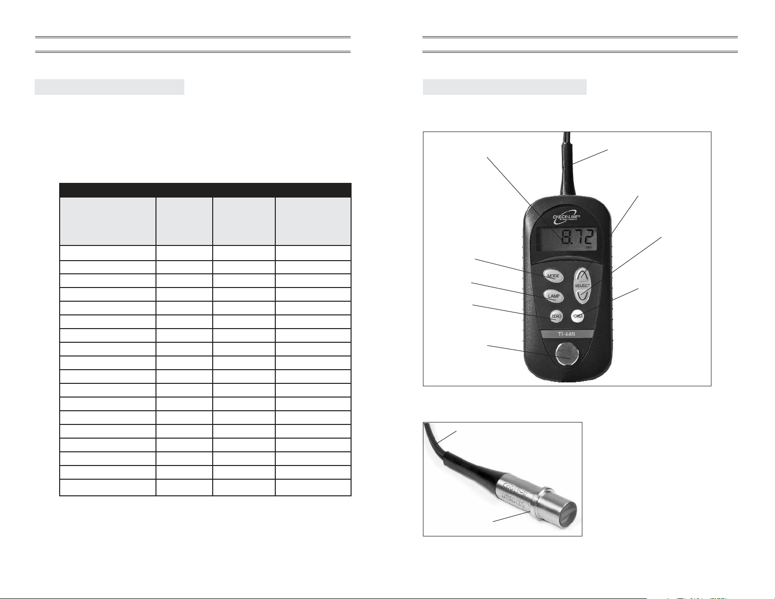
Mode Selector
Back Light
On/Off
Probe Zero
Test Plate for
Zero Adjustment
Equivalent to 0.197"
(5.00 mm) steel
On/Off Switch
Hard-wired cable and probe
LCD Display
Increase Sonic
Velocity
or Thickness
Adjustment
Decrease Sonic
Velocity or
Thickness
Adjustment
Probe
3.0 DESCRIPTION OF GAUGE
3.1 Gauge
3.2 Probe Assembly
Probe Cable: Do not bend sharply.
Do not bring into contact with high
temperature objects (> 60 °C)
TI-44N Operating Instruction Guide
3
APPENDIX
The TI-44N Thickness Gauge is supplied from the factory set for an acoustic
velocity of 5930 m/sec for the measurement of steel. To measure the thickness of
any other material, the acoustic velocity must be changed. When checking the
built-in calibration sample, the gauge will display the “Equivalent Value” listed in
the Table in section 6.1, instead of 0.197" (or 5.0 mm)
ACOUSTIC VELOCITY SELECTION TABLE
Material Acoustic Equivalent Equivalent
Type Velocity Value Value Of
(meters/sec) Of Calibration Calibration Disc
Disc (Inch) Disc (mm)
Aluminum 6260 .208 5.3
Acrylic (Plexiglass) 2700 .090 2.3
Cast Iron 4400-5000 .148 - .168 3.8 - 4.3
Ceramics 10000 .332 8.4
Copper 4700 .156 3.9
Duralumin (17S) 6320 .211 5.3
Ebonite 2500 .083 2.1
Glass 5570 .185 4.7
Nickel 6040 .201 5.1
Polyethylene (Soft) 1900 .063 1.6
Polyvinyl Chloride (PVC) 2300-2500 .077-.083 1.9 - 2.1
Quartz (X cut) 5720 .191 4.9
Stainless Steel (SUS304) 5790 .193 4.9
Stainless Steel (SUS403) 6100 .205 5.2
Stainless Steel (SUS410) 7390 .246 6.2
Steel 5930 .197 5.0
Tin 3320 .110 2.8
Zinc (Zn) 4170 .139 3.5
◆
◆
◆
◆
◆
◆
◆
◆
◆
◆
◆
◆ Denotes one of the 10 preset values in Mode C.
TI-44N Operating Instruction Guide
18
Page 4
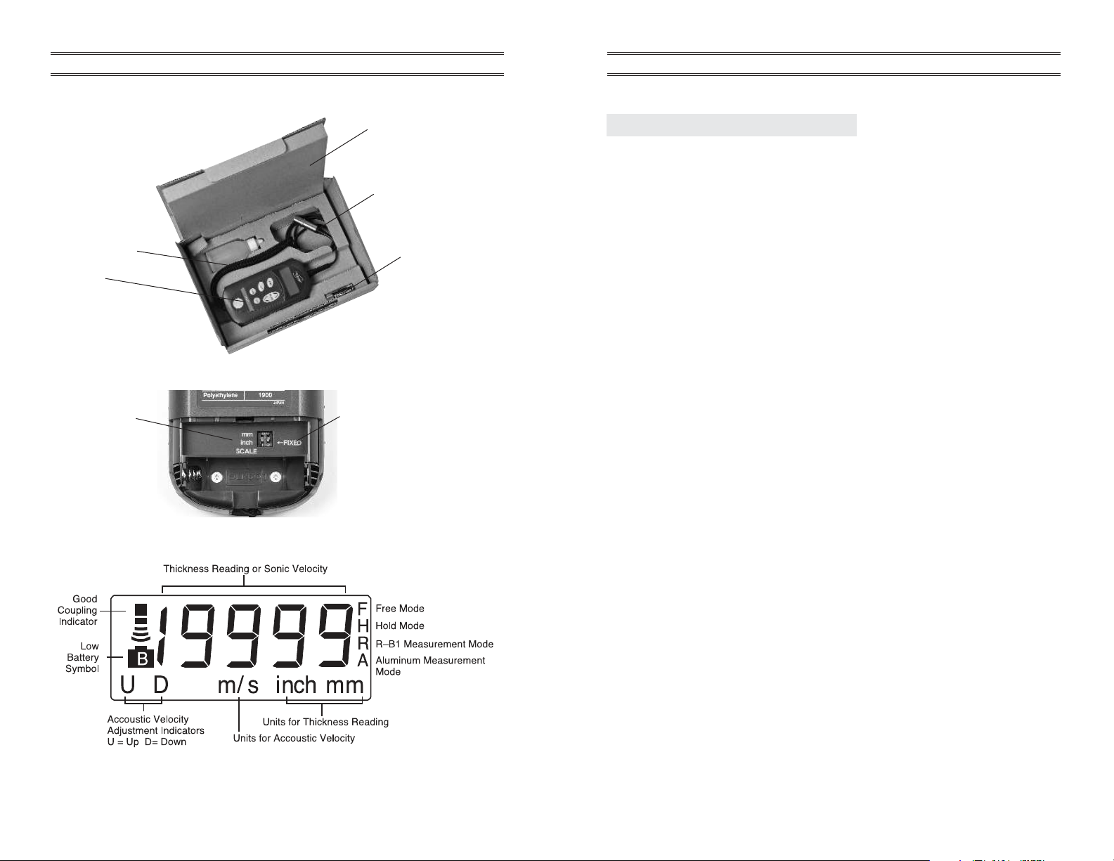
3.3. Complete Kit
3.4 Battery Compartment
3.5 LCD Display
Units of Measure
Selector Switch
Gauge
Coupling Fluid
Operating Instructions
Probe/Cable Assembly
Battery
Probe selection switch
set on FIXED
Bottom of gauge
Use AA-type alkaline battery
TI-44N Operating Instruction Guide
4
9.0 SPECIFICATIONS
Range (steel) Flat plate 1.00 to 199.99
mm
Pipe 30 in. diameter and 1.50 in. thickness or more
Accuracy
(mm)
±0.02
Errors
(mm)
1.00 to 99.9 ±0.05
100.00 to 199.99 ±2% / rdg
Probe (standard) 5Z10NDT-Ma
Probe Cable HF coaxial cable: 1.5 D-QEVX2C, 1.0m
Object Material Iron, steel, aluminum, any other metal, hard plastics,
glass and ceramics
Sonic Velocity 1,000 – 12,000 m/s
Adjustable Range (10 predefined sonic velocities stored in gauge)
Display Digital LCD display with backlight
Display Resolution 0.01
mm
(1.00mmto 199.9mm)
Display Frequency Approx. 3 times / sec
Digits 4-1/2 (max 19999) the upper digit displays 1 only
Start-up Time Approx 2 Sec.
Power Supply 1 AA-type alkaline battery, 1.5 V
Operating Time >30 hours continuous operation
Usage: 2 sec. measurement followed by 10 sec
standby
Test Panel for 5.00 mm thickness for steel (sonic velocity 5930 m/s)
Zero Adjustment come standard with gauge
Weight Meter: approx 150 g. Probe: Approx. 50 g
Dimensions 69 (W), 144 (L), 30 (H) mm
Operating Temperature -5 °C to 55 °C
Storage Temperature -10 °C to 55 °C
Warranty Meter: 1 year. Probe: 90 days
TI-44N Operating Instruction Guide
17
Page 5

4.0 GETTING STARTED
4.1 Setting Units Of Measure
Remove the Battery Cover on the back side of the gauge
by pressing it down with your thumb and sliding it in the
direction indicated by the arrow. The Units Selector Switch
is located in the Battery Compartment. Slide the switch to
either the Inch (up) or mm (down) position as desired.
Inch is the factory default unit of measure .
4.2 Installing The Battery
Remove the Battery Cover on the back side of the gauge by pressing it down
with your thumb and sliding it in the direction indicated by the arrow. Place
one (1) AA-size battery (1.5 Volt) into the battery compartment in the
orientation shown on the sketch. Replace the Battery Cover.
AA Battery
mm
Inch
+
–
Correct Battery Orientation
Battery
Compartment
TI-44N Operating Instruction Guide
5
Description of Problem Possible Cause Action To Be Taken
Fluxuating readings Defective probe Return to manufacturer
Fluxuating readings while Aluminum measurement Switch to aluminum mode
measuring aluminum is being taken in standand
mode
No reading or wildly Measurment is being taken Switch to R to B1mode
fluxuating reading while in S to B1mode
measuring resin
Flashing coupling signal Probe or meter failure or Return to manufacturer for
and/or reading is displayed deterioratioin service
while the measurement is
in standby
Sonic velocity reading • Effect of external noise • Change use location
cannot be modified (fixed
to 5930 m/s) • Meter failure • Return to manufacturer for
service
Measurement of Test • Accoustic Velocity not • Change velocity to 5930
Plate does not show set to 5930 (steel) 5930 µs.
0.197”
(5.00mm)
(Refer to section 5.0)
TI-44N Operating Instruction Guide
16
Page 6

4.3 Turning The Power ON
Turn on the power by pressing the POW key. The current acoustic velocity
setting will be momentarily displayed prior to entering the Measurement
Mode (Mode H). The display should then read 0.000 inch (or 0.00 mm).
If the Good Coupling Indicator is flashing on and off, the red transmit
connector of the probe is not connected properly.
4.4 Turning The Power OFF
The Power will turn off automatically after three (3) minutes of non-use.
To manually turn off the power, press & hold the POW key for 3 sec.,
then release.
4.5 Zero Adjustment
This operation adjusts the zero point of the probe. Zero adjustment data is stored in
the instrument. It is recommended that the zero
adjustment data be refreshed once a day, preferably
before starting the day’s work.
1 . Apply couplant on the test plate surface and
place the probe on it.
2 . Make sure the probe is in good contact with
the test plate surface and press the ZERO
switch.
3 . The zero adjustment procedure takes place and the display reads 0.197" or
5.00 mm when the process has been successfully completed.
NOTE: When the sonic velocity is set to a value other than 5390 m/s, the
display reads 0.197" or 5.00 momemtarily when the ZERO switch
is pressed. Zero adjustment is nonetheless proceeding correctly.
If the material to be tested is signifcantly larger or smaller than
0.197" or 5.00mm, and the ZERO switch is pressed, the display
will read --- -and the zero adjustment process becomes invalid. In
this case, the zero adjustment should be made on a sample of known
thickness of the test material itself.
4.6 Using Couplant Fluid
Apply couplant fluid to the mesuring surfacae before measurement. The
couplant eliminates air between the probe and test surface, promoting the
transmission of the ultrasonic pulse.
NOTE: Never use organic solvents, including thinners and alcohols.
The surface must be cleaned of couplant after measurement.
TI-44N Operating Instruction Guide
6
8.0 TROUBLE-SHOOTING GUIDE
Description of Problem Possible Cause Action To Be Taken
Gauge will not power Battery voltage may be Replace with new AA
up too low battery
Gauge will not power • New battery may be • Check battery voltage
up even though battery too weak (should be ≈1.5 Volt)
has been replaced
• Back-up battery (lithium) • Return gauge for a new
could be too weak lithium battery
Good Coupling
• Probe or cable could be • Clean probe & surface
Indicator flashes on/off defective and retry measurement
• Foreign substance may • Return to manufacturer
be trapped between for inspection/repair
probe and sample
Good Coupling
• Insufficient couplant fluid • Add more couplant
Indicator not shown
• Paint or coating is too • Grind off paint and/or
thick or voids and/or corrosion
corrosion lies under paint
“......” is displayed Probe could be degraded Return to manufacturer
when ZERO key is or defective for inspection or repair
pressed
Displayed thickness Acrylic probe face is Carefully sand face of
value is unstable deteriorated probe using #500 paper
Can’t obtain measure- Pipe diameter (OD) may Consult factory
ment on small dia. pipe be less than 1”
(25 mm)
Couping indicator does • Insufficient amount of • Apply additional couplant
not appear while measure- couplant
ment is being taken • Test material surface is • Grind/polish measuring
too rough surface to 50-100-s
smoothness
• Test material bottom • Change measurement
surface is too rough point
• Too much ultrasonic • Change measurement
attenuation due to point
material composition
• Test material thickness is • Change measurement
outside the proper point
measuring range
Fluxuating readings Defective probe Return to manufacturer
TI-44N Operating Instruction Guide
15
Page 7

5.0 QUICK STA RT INSTRUCTIONS - STEEL THICKNESS
These Quick Start procedures are intended for those applications where the thickness
of steel is to be measured.
If a material other than steel will be measured, the acoustic velocity must be adjusted
to the appropriate value. In this case refer to Changing Acoustic Velocity Settings in
section 6.3
1. Turn the power on by pressing the POW key.
2. Check the calibration by placing a drop of coupling on the built-in calibration
disc on the front face of the gauge.
3. Grasp the probe and place it on the calibration disc.
4. The display should show a reading of 0.197 Inch ±0.001"
or 5.00 mm ±0.01 mm,along with the Good Coupling
Indicator located in the upper left side of the LCD display.
The indicator will remain on the display while the probe is in contact with the
sample.
5. If the gauge shows any other value press the
ZERO key while the probe remains
in contact with the calibration disc. The reading should then be adjusted to read
correctly. The gauge is now ready to perform thickness readings on steel
samples.
6. Place a small amount of coupling fluid on the steel surface to be measured and
proceed as indicated in step 3 above.
7. The gauge will display the thickness of the steel wall along with the Good
Coupling Indicator. The Indicator will remain on the display while the probe is
in contact with the sample. If the Indicator is not displayed, then the
measurement was not successful and should be repeated.
Good Coupling
Indicator
NOTES
a. When the probe is removed from the sample after a measurement, the last reading
will be stored.
b. The gauge will power off automatically after 3 minutes of non-use. To manually
turn off the power, press and hold the POW key for 3 or more seconds and then
release.
c. Refer to Trouble-shooting Guide if any problems occur.
TI-44N Operating Instruction Guide
7
7.1 Notes On Measurements
1. The following surface conditions can prevent accurate measurements.
(Refer to section 7.2 Preparing The Surface For Measurement.)
• More than 0.012" (12 mils or 300 microns) of paint or other coating
• Flaking or loosely adhered coatings
• Rough or heavily-pitted surface
2 . If the Good Coupling Indicator is not shown on the display when the
probe is in contact with the sample or if it flashes on and off, the
following possibilities could exist:
• Some foreign substance (other than coupling fluid) could be present
between the probe and the sample (i.e. dust, sand, dirt, etc.)
• Extent of corrosion is too heavy
• A problem exists in the receiving (green) side of the cable or connector
3. If two materials are press-fitted or laminated together, the gauge will only
read the thickness of the sample that the probe contacts.
4. Pipes with outer diameters less than 1 Inch (25 mm) cannot be measured.
Specify Model TI-25.
5. Measurement of materials at or above 140 °F (60 °C) will damage the probe
and should be avoided.
7.2 Preparing The Surface For Measurement
The TI-44N Gauge can be used to measure thickness over existing paint or
coatings as long as the coating is in good condition, is well adhered to the
surface and does not exceed 0.012" (12 mils or 300 microns) in thickness.
Please note that the paint or coating thickness will be included in the overall
wall thickness measurement.
If the surface to be measured is rusty, heavily pitted or corroded, it will have
to be prepared using a wire brush, grinder, file or sandpaper. Additionally, if
the surface is still rough after preparation, use of a more viscous couplant
fluid (i.e. water-based K-Y Jelly) will help obtain a good acoustic coupling.
K-Y Jelly is also a good choice when measuring on vertical surfaces or on
the underside as it will help adhere the probe to the measurement surface
while also acting as a coupling agent.
TI-44N Operating Instruction Guide
14
Page 8

6.0 SETUP FOR MEASURING THICKNESS OF MATERIALS
OTHER THAN STEEL
The TI-44N Thickness Gauge is supplied from the factory set for an acoustic velocity
of 5930 m/sec for the measurement of Steel. To measure the thickness of any other
material, the acoustic velocity must be changed. When checking the built-in calibration disc, the gauge should display the “Equivalent Value” listed in the Table in section 6.1, instead of 0.197" or 5.0 mm for steel.
To determine the proper acoustic velocity for measurement of the non-steel material,
refer to the Acoustic Velocity Selection Table in section 6.1. After determining the
proper acoustic velocity, the gauge must be changed to this new value as described
in section 6.3 Changing The Acoustic Velocity Settings.
If you do not know the type of material to be measured or the material type is not
listed in the Acoustic Velocity Selection Table, refer to section 6.2, Setup Of Gauge
When Acoustic Velocity is Unknown
TI-44N Operating Instruction Guide
8
7.0 TAKING MEASUREMENTS
After setting the gauge for the correct acoustic velocity for the material to be measured or retaining the factory preset value of 5930 m/sec for measurement of steel, the
gauge is ready to take measurements.
A coupling fluid must be used between the probe and the sample to obtain measurements. Atwo (2) ounce bottle is supplied with the gauge. We highly suggest using
this water soluble couplant. Long-term use of petroleum-based couplants (grease,
oil, etc.), salt water or chemical solvents will eventually damage the probe.
Additional bottles of coupling fluid are available from the gauge supplier.
1. Turn the power on by pressing the
POW key.
2. Place a small amount of coupling fluid on the calibration disc located on the
face of the instrument.
3. Grasp the probe by the holding the spring-loaded centering shell and place it on
the calibration disc. Press the shell down until it contacts the surface.
4 . Confirm that the calibration disc measures 0.197" (± 0.001") or
5.0 mm (± 0.01mm) or the “Equivalent Value” as found in the Acoustic Velocity
Selection Table for non-steel materials.
5. Place a small amount of coupling fluid on the surface to be measured, press
probe onto the surface and proceed as indicated in step 3 above.
The gauge will display the thickness of the material or wall along with the Good
Coupling Indicator. The Indicator will remain on the display while the probe is in
contact with the sample.
If the Good Coupling Indicator is not displayed, then the measurement was not
successful and should be repeated. If this problem persists then the surface may
not be in acceptable condition for measurement. Refer to Preparing The Surface
For Measurement, section 7.2.
Good Coupling
Indicator
TI-44N Operating Instruction Guide
13
Page 9

6.1 Acoustic Velocity Selection Table
ACOUSTIC VELOCITY SELECTION TABLE
Material Acoustic Equivalent Equivalent
Type Velocity Value Value Of
(meters/sec) Of Calibration Calibration Disc
Disc (Inch) Disc (mm)
Aluminum 6260 .208 5.3
Acrylic (Plexiglass) 2700 .090 2.3
Cast Iron 4400-5000 .148 - .168 3.8 - 4.3
Ceramics 10000 .332 8.4
Copper 4700 .156 3.9
Duralumin (17S) 6320 .211 5.3
Ebonite 2500 .083 2.1
Glass 5570 .185 4.7
Nickel 6040 .201 5.1
Polyethylene (Soft) 1900 .063 1.6
Polyvinyl Chloride (PVC) 2300-2500 .077-.083 1.9 - 2.1
Quartz (X cut) 5720 .191 4.9
Stainless Steel (SUS304) 5790 .193 4.9
Stainless Steel (SUS403) 6100 .205 5.2
Stainless Steel (SUS410) 7390 .246 6.2
Steel 5930 .197 5.0
Tin 3320 .110 2.8
Zinc (Zn) 4170 .139 3.5
◆
◆
◆
◆
◆
◆
◆
◆
◆
◆
◆
◆ Denotes one of the 10 preset values in Mode C.
TI-44N Operating Instruction Guide
9
6.5 Changing Modes
Flow of mode selection:
S to B1measurement method
Standard Thickness value
Measurement Ex.: 5.00 mm
F/ H appears on the extreme
right in Free / Hold mode,
respectively.
Aluminum Thickness value followed by A
Measurement Ex.: 5.00 mm_A
F/H appears on the extreme
right in Free/Hold mode,
respectively.
TI-44N provides two measurement modes depending
upon the nature of the test material (Standard and
Aluminum mode), which can be easily switched by
MODE switch operation:
Pressing and holding the MODE switch for longer than two seconds always
toggles back and forth between the Free and Hold modes.
Free mode is the correct choice for almost all applications. Select the Hold
mode when readings fluxuate and stable measurement cannot be obtaned.
TI-44N Operating Instruction Guide
12
Page 10

6.2 Setup Of Gauge When Acoustic Velocity Is Unknown
In applications where the type of material is not known or the material type
is not listed in the Acoustic Velocity Selection Table the following steps can
be performed to set the gauge to measure accurately.
1. Measure a sample of the material using a micrometer, caliper or similar
measuring device.
2. Turn the power on by pressing the POW key.
3. Place a small amount of couplant fluid on the sample and place the probe
on the sample.
4. After a thickness value is shown on the LCD display along with the Good
Coupling Indicator, remove the probe from the sample.
5. Use the
▲ and ▼ keys to increase or decrease the displayed value until
it equals the known thickness of the sample as measured in Step 1. When
the
▲ key is pressed the “UP” indicator will be show on the LCD display.
The “LOW” indicator will be shown for the ▼ key.
6. The acoustic velocity setting will be automatically adjusted to the correct
value for this material after Step 5 is completed.
7 . Change modes to either Mode C or Mode A to display the current acoustic
velocity, as described in section 6.4. Write this value down so it can be
re-entered without having to repeat the above procedures should you need
to change the acoustic velocity to another setting.
6.3 Changing Acoustic Velocity Settings
After determining the required acoustic velocity for the material to be
measured, the acoustic velocity must be adjusted by using either of the
following methods:
• Selecting one of the ten (10) preset values [Mode C, Coarse Adjustment]
• Adjusting the velocity to the desired setting [Mode A, Fine Adjusment]
METHODS FOR CHANGING ACOUSTIC VELOCITY SETTINGS
MODE Select one from Use ▲ or ▼ Last Setting ➔1900 ➔2700 ➔
C a list of 10 keys to index ➔ 4170 ➔ 4700 ➔ 5570 ➔ 5790
Preset Values thru selections ➔ 5930 ➔ 6260 ➔7390 ➔10000
MODE Fine Adjustment Use ▲ or ▼ Any acoustic value can be set
A to desired value keys to increase from 1000 to 12000 m/sec
or decrease value
TI-44N Operating Instruction Guide
10
6.4 Thickness Measurement Methods
(a) Standard mode vs. aluminum mode
The instrument is shipped with the standard sensitivity settings suitable
mainly for steel measurement. In addition to this, it provides an aluminum
measurement mode with lower sensitivity (approx. 10 dB less than the
standard mode).
High-sensitivity equipment will often pick up too much noise when
measuring materials with small ultrasonic attenuation (e.g. aluminum),
resulting in erroneous thickness values.
(b) S to B 1method
Thickness (D) is determined using the
time difference between the upper surface
reflection (S-echo) and the first bottom
surface reflection (B-echo). This method
is mainly used for steel measurement.
TI-44N Operating Instruction Guide
11
Page 11

ELECTROMATIC
E Q U I P M E N T C O., I N C.
600 Oakland Ave., Cedarhurst, NY 11516–U.S.A.
TEL: 516-295-4300 • FAX: 516-295-4399
CHECK•LINE
®
INSTRUMENTS
CHECK•LINE
®
BY ELECTROMATIC
TI-44N
Operating Instructions Guide
 Loading...