

Page 1

-1-
TABLE OF CONTENTS
01.0 Introduction . . . . . . . . . . . . . . . . . . . . . . . . . . . . . . . . . . . . . . . . . . . . . . . 02
1.1 Upacking
1.2 Optional Accessories
2.0 Operation . . . . . . . . . . . . . . . . . . . . . . . . . . . . . . . . . . . . . . . . . . . . . . . . .
03
2.1 First Installation
2.2 Internal Sensor Calibration
2.3 ZERO Adjustment
2.4 GAIN Adjustment
2.5 Checking The Adjustment
3.0 Specifications . . . . . . . . . . . . . . . . . . . . . . . . . . . . . . . . . . . . . . . . . . . . . .
07
4.0 Pin Assignments. . . . . . . . . . . . . . . . . . . . . . . . . . . . . . . . . . . . . . . . . . . .
07
5.0 Appendix: Available Models . . . . . . . . . . . . . . . . . . . . . . . . . . . . . . . . . .
08
5.1 TE Models
52. TP Mocels
5.3 TE-24 Models
5.4 TE-22 Models
5.5 TF Models
5.6 TERX Models
5.7 BTMS Models
6.0 Warranty . . . . . . . . . . . . . . . . . . . . . . . . . . . . . . . . . . . . . . . . . . . . . . . . . 12
-12-
6.0 WARRANTY
ELECTROMATIC Equipment Co., Inc. (ELECTROMATIC) warrants to theoriginal
purchaser that this product is of merchantable quality and confirms in kind and quality
with the descriptions and specifications thereof. Product failure or malfunction arising
out of any defect in workmanship or material in the product existing at the time of
delivery thereof which manifests itself within one year from the sale of such product,
shall be remedied by repair or replacement of such product, at ELECTROMATIC’s
option, except where unauthorized repair, disassembly, tampering, abuse or misapplication has taken place, as determined by ELECTROMATIC. All returns for warranty
or non-warranty repairs and/or replacement must be authorized by ELECTROMATIC,
in advance, with all repacking and shipping expenses to the address below to be borne
by the purchaser.
THE FOREGOING WARRANTY IS IN LIEU OF ALL OTHER WARRANTIES,
EXPRESSED OR IMPLIED, INCLUDING BUT NOT LIMITED TO, THE
WARRANTY OF MERCHANTABILITY AND FITNESS FOR ANY PARTICULAR
PURPOSE OR APPLICATION. ELECTROMATIC SHALL NOT BE RESPONSIBLE
NOR LIABLE FOR ANY CONSEQUENTIAL DAMAGE, OF ANY KIND OR
NATURE, RESULTING FROM THE USE OF SUPPLIED EQUIPMENT, WHETHER
SUCH DAMAGE OCCURS OR IS DISCOVERED BEFORE, UPON OR AFTER
REPLACEMENT OR REPAIR, AND WHETHER OR NOT SUCH DAMAGE IS
CAUSED BY MANUFACTURER’S OR SUPPLIER’S NEGLIGENCE WITHIN
ONE YEAR FROM INVOICE DATE.
Some State jurisdictions or States do not allow the exclusion or limitation of incidental
or consequential damages, so the above limitation may not apply to you. The duration
of any implied warranty, including, without limitation, fitness for any particular
purpose and merchantability with respect to this product, is limited to the duration of
the foregoing warranty. Some states do not allow limitations on how long an implied
warranty lasts but, not withstanding, this warranty, in the absence of such limitations,
shall extend for one year from the date of invoice.
ELECTROMATIC Equipment Co., Inc.
600 Oakland Ave. Cedarhurst, NY 11516—USA
Tel: 1-800-645-4330/ Tel: 516-295-4300/ Fax: 516-295-4399
Every precaution has been taken in the preparation of this manual. Electromatic Equipment Co., Inc., assumes
no responsibility for errors or omissions. Neither is any liability assumed for damages resulting from the use of
information contained herein. Any brand or product names mentioned herein are used for identification purposes only, and are trademarks or registered trademarks of their respective holders.
Page 2
-2-
1.0 INTRODUCTION
These Operating Instructions refer to Model TE sensor; they are also applicable to the
following models:
TP, TE-24, TE-22, TF, TERX, BTMS
1.1 Unpacking
When the sensor is delivered without a display and data analysis unit:
1 Diode connector, 8-pin
1 Operating Instructions
Unpack the instrument and inspect it for any shipping damage. Notices of defect
must be filed immediately, at the latest within 10 days on receipt of the goods.
1.2 Optional Accessories
Option DC: Analog output 0 - 10 V DC
Option MA: Analog output 4 - 20 mA
-11-
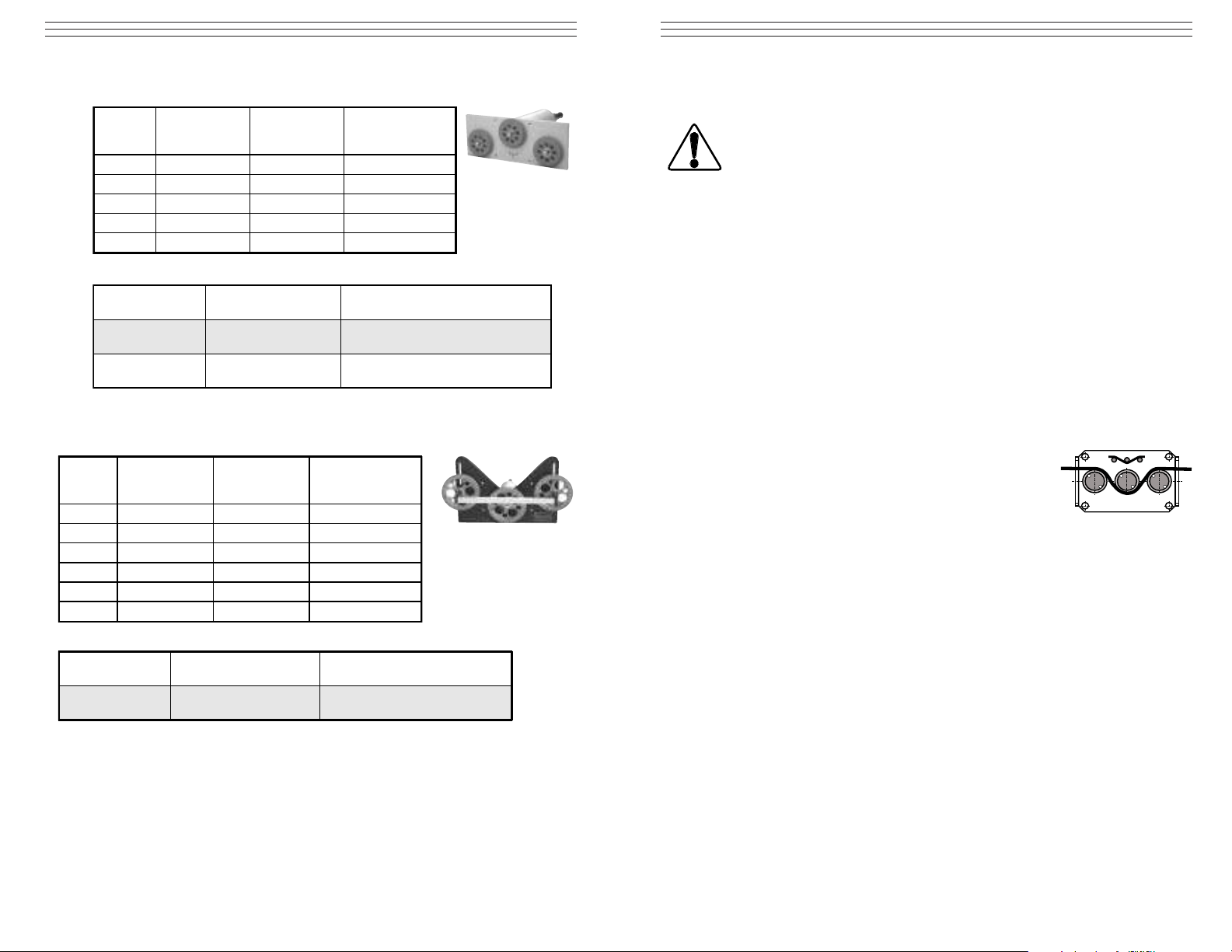
5.7 BTMS Models
5.6 TERX Models
Model
TERX-100
TERX-200
TERX-500
TERX-1000
TERX-2000
TERX guide rollers:
Guide Rollers
Ten s ion Ran g es
0 - 1000 60 7, 10, 15, 20
0 - 2000 120 7, 10, 15, 20
Standard
Model
BTMS-1000
BTMS-2000
BTMS-5000
BTMS-10K
BTMS-20K
BTMS-50K
BTMS guide rollers:
Guide Rollers
Tension Ranges
cN
0 - 1000 30, 36, 41, 50, 100
0 - 2000 30, 36, 41, 50, 100
0 - 5000 10, 15, 20, 30, 36, 41, 50, 100
0 - 10 daN 10, 15, 20, 30, 36, 41, 50, 100
0 - 20 daN 10, 15, 20, 30, 36, 41, 50, 100
0 - 50 daN 10, 15, 20, 30, 36, 41, 50, 100
Standard
*
cN
0 - 100 60 7, 10, 15, 20
0 - 200 60 7, 10, 15, 20
0 - 500 60 7, 10, 15, 20
Measuring
Head Width mm
Line Speed
m/min max.
1000
Roller Widths
Line Speed
m/min max.
1000 Hardcoated aluminium
Roller Widths
Roller Material
Hardcoated aluminium
(Exception: 7 mm rollers
are made of nickel-plated steel)
Roller Material
Page 3
-3-
2.0 OPERATION
2.1 First Installation
1. Install the sensor at the desired measuring location.
2. Connect the sensor with the supplied or existing display unit. The pin
assignment of the 8-pin connector located on the rear side of the sensor is
described in section 4.0.
3. If the material path is other than vertical or if the process material deviates
significantly from the factory calibration material, you have to carry out
zero and gain adjustment, as described in
section 2.3 adn 2.4, before
first installation.
3. Wait approx.10 minutes for the sensor to warm up.
4. Thread the process material through the measuring
rollers, following the thread acquisition symbol on
the front of the sensor.
2.2 Internal Sensor Calibration
General Notes:
If the sensor was delivered together with a display unit, ZERO and GAIN
adjustment should only be performed on the supplied display unit.
All tension meters are calibrated with standard materials—such as polyamidemonofilament (PA)—according to the factory procedure; the material path is
vertical (Model BTMS horizontal).
Any difference in process material size and rigidity from the standard material
may cause a deviation of the accuracy.
In 95% of all industrial applications the factory calibration has been proven
to provide the best results and is used for comparative purposes.
If required, you can operate the sensors with a material path other than
vertical.
If the process material differ significantly in size, rigidity and shape we recommend special calibration using customer material. In the case of a material path
other than vertical or special calibration using customer material you have to
carry out static zero and gain adjustment once again as described i
n Chapters
3.2.1 and 3.2.2.
The device must not be operated in explosion hazard areas and must not come
into contact with aggressive substances.
To avoid damage, do not move the center roller by hand.
Tensions that exceed the tension range of the device by more than 100%
may cause a permanent deformation of the measuring spring and must be
avoided under any circumstances.
-10-
5.4 TE-22 Models
5.5 TF Models
Model
TE-22-50
TE-22-100
TE-22-200
TE-22-500
TE-22-1000
TSL guide rollers:
V-g ro ove d
Standard
Option
Model
TF-100
TF-200
TF-500
TF-1000
TF-2000
TF-5000
TSF guide rollers:
Tensi on Ra ng es
0 - 100 270 PA: 0.30 mm Ø
0 - 200 270 PA: 0.50 mm Ø
0 - 500 270 PA: 0.80 mm Ø
V-g ro ove d
Standard
Tension Ranges
cN
0 - 50 150 PA: 0.12 mm Ø
0 - 120 150 PA: 0.12 mm Ø
0 - 200 150 PA: 0.12 mm Ø
0 - 400 150 PA: 0.20 mm Ø
0 - 1000 15 PA: 0.30 mm Ø
T
cN
0 - 120 270 PA: 0.12 mm Ø
0 - 200 270 PA: 0.12 mm Ø
0 - 400 270 PA: 0.20 mm Ø
Head Width mm
Line Speed
m/min max.
*
Measuring
Head Width mm
Line Speed
m/min max.
4000
4000
*
Measuring
5000
**
FACTORY
Calibration Material
Hardcoated aluminium
(Same dimension as standard roller)
**
FACTORY
Calibration Material
Roller Material
Hardcoated aluminium
(Nr. R12045)
Roller Material
(Nr. R12021)
Plastic (PVC reed)
WARNING
Page 4

-4-
2.3 ZERO Adjustment
1. Install the sensor at the measruing locations in the desired measuring position,
using the provided mounting holes.
2. Remove the countersunk head screws (M2.5)
ZERO and GAIN on the rear side of the
sensor.
3 .Wait approx. 10 minutes for the measuring
head to warm up.
4. Thread the process material through the
measuring rollers, following the thread
acquisition symbol on the front of the sensor.
NOTE: Since zero and gain adjustments are always performed statically the
display values may differ under dynamic load.
5. Suspend a weight that corresponds to, for example, 10% of the tension range
from the measured material (see diagarm above).
6. Connect a voltmeter to pins 1 and 7 of the connector provided on the rear side
of the sensor. See section 4.0
When threading the process material through the rollers,
follow the material acquisition symbol on the front of the
sensor. If force is applied to the middle sensing roller in
the incorrect direction, damage could result.
W
-9-
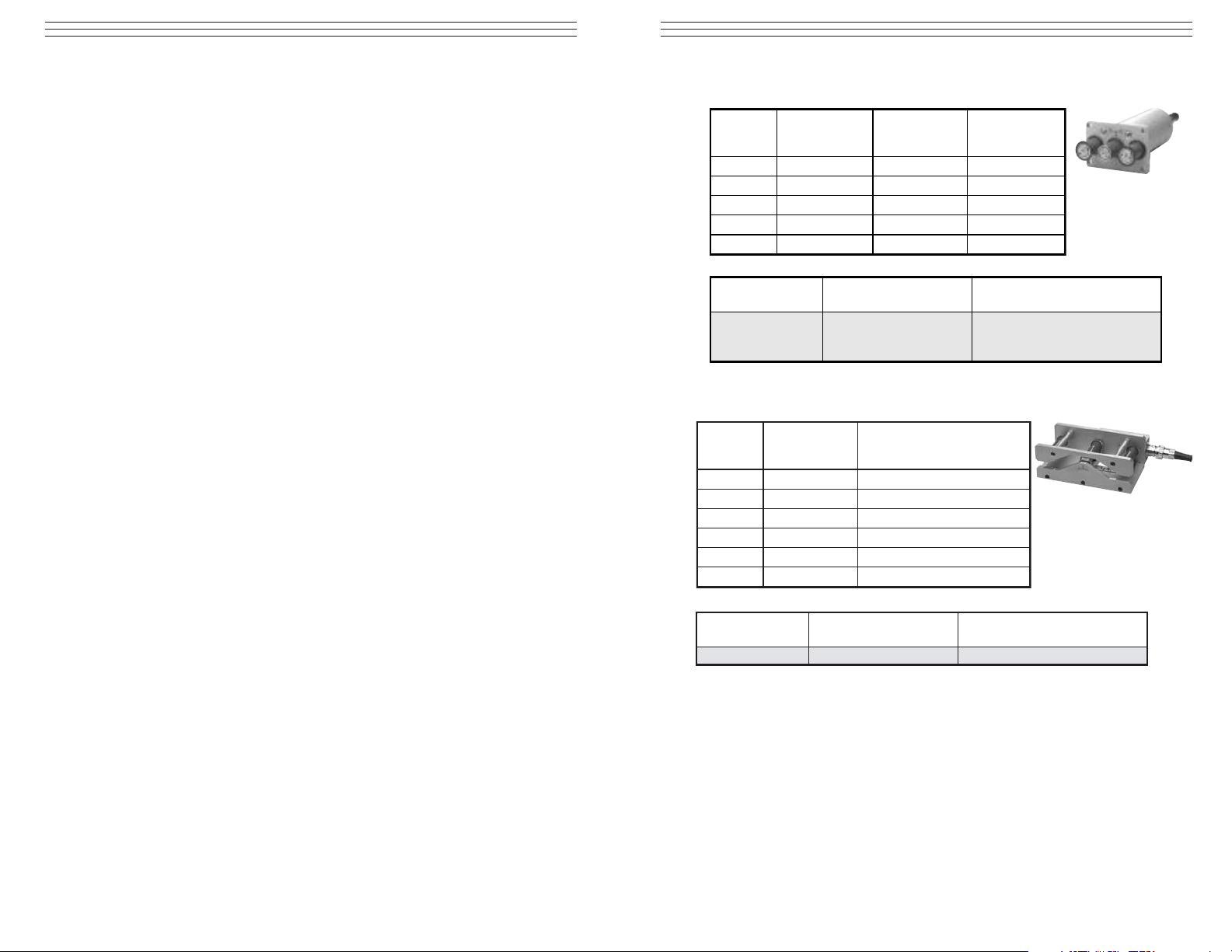
5.2 TP Models
5.3 TE-24 Models
Mounting holes 4 x
Guide rollers 2x
Measuring
roller
Material path
symbol
Model
TP-50
TP-100
TP-200
TP-500
TP guide pins:
Tension Ranges
0 - 120 64 PA: 0.12 mm Ø
0 - 200 64 PA: 0.12 mm Ø
0 - 400 64 PA: 0.20 mm Ø
Guide Pins
Standard
*
cN
0 - 50 64 PA: 0.12 mm Ø
Measuring
Head Width mm
Line Speed
m/min max.
6000 Oxide ceramic 4 mm Ø (Nr. R12056)
**
FACTORY
Calibration Material
Pin Material
Weight
GAIN
ZERO
ARNING
Model
TE-24-1000
TE-24-2000
TE-24-5000
TE-24-10K
TE-24-20K
TE-24-50K
TE-24 guide rollers:
Tension Ranges
0 - 1000 150 PA: 0.30 mm Ø
0 - 2000 150 PA: 0.50 mm Ø
0 - 5000 150 PA: 0.80 mm Ø
0 - 10 daN 200 PA: 1.00 mm Ø
0 - 20 daN 200 PA: 1.50 mm Ø
0 - 50 daN 200
V-g ro ove d
Standard
U-grooved
Option R1
cN
*
Measuring
Head Width mm
Line Speed
max. m/min
4000
4000
**
FACTORY
Calibration Material
Steelrope 1.50 mm Ø
(7 x 7 x 0.20)
Roller Material
Hardened steel roller
(Nr. R10006)
Hardened steel roller
(Radius R5)
Page 5

-5-
7. Insert a screw driver (with a point width of up to 1.9 mm) into the now
accessible ZERO opening of the housing and adjust the potentiometer until
the connected voltmeter shows a measured voltage of, for example:
Sensor Model TS -200:
Weight 20 cN = Display 0.100 V for the TS standard version
or
Weight 20 cN = Display 1.00 V for the TS version with 10 V output signal.
2.4 GAIN Adjustment
Requirement: ZERO adjustment (section 2.3)t must be carried out first.
1. Thread the process material through the measuring rollers, following the
thread acquisition symbol on the front of the sensor.
2. Suspend a weight that corresponds to, for example, 95% of the tension range
from the measured material (see diagram on page 4).
3. Insert a screw driver (with a point width of up to 1,9 mm) into the now
accessible GAIN opening of the housing(see diagram on page 4) and adjust
the potentiometer until the connected voltmeter shows a measured voltage of,
for example:
Sensor Model TS-200:
Weight 190 cN = Display .950 V for the TS standard version
or
Weight 190 cN = Display 9.50 V for the TS version with 10 V output signal.
4. Check the adjustment with a fresh portion of the process material and repeat
the adjustments if required, following the direction in section 2.3 and 2.4.
5. Screw in the countersunk head screws
ZERO and GAIN on the rear side of the
sensor.
Do not tilt the screwdriver as this may damage the
potentiometer.
-8-
5.0 APPENDIX: AVAILABLE MODELS
In addition to the standard specifications listed below, the following custom modifications are also available:
■ Special tension ranges
■ Customized roller dimensions
■ Special calibration using customer supplied material
5.1 TE Models
Model
TE-50
TE-100
TE-200
TE-500
TE-1000
TE-2000 0 - 2000 124 PA: 0.50 mm Ø
TE-5000
TE-10K 0 - 10 daN 124 PA: 1.00 mm Ø
TE-20K
TE-50K
TE Guide Rollers
V-grooved
Option
Option
Option
Option
Option
Option
Option
Asymmetrical groove
U-grooved
Option
Tensi on
Ranges
cN
0 - 50 64 PA: 0.12 mm Ø
0 - 100 64 PA: 0.12 mm Ø
0 - 200 64 PA: 0.12 mm Ø
0 - 500 64 PA: 0.20 mm Ø
0 - 1000 64 PA: 0.30 mm Ø
0 - 5000 124 PA: 0.80 mm Ø
0 - 20 daN 224 PA: 1.50 mm Ø
0 - 50 daN 224
Standard
K
H
T
W
ST
B
CE
ASY
U
*Measuring
Head Width
mm
Line Speed
m/min max.
2000 Hardcoated aluminium (Nr. R10008)
3500 Hardcoated aluminium
5000
1000 Plastic (POM) black
1000 Nickel-plated steel
1000 Hardened steel
1000
1000 Ceramic
1000
2000 Hardcoated aluminium
Calibration Material
Steel rope: 1.50 mm Ø
(for Model TE-100 and higher ranges)
Steel tempred, especially for measuring
(for Model TE-100 and higher ranges)
**FACTORY
(7 x 7 x 0.20)
Roller Material
Plasma-coated aluminium
Tyrecord
Hardcoated aluminium
WARNING
GAIN
ZERO
Page 6

-6-
2.5 Checking the Adjustment
For general information, refer to section 2.2.
Requirements:
1. The sensors must be installed at the measuring location. Connect the sensor
with the supplied or existing display unit.
NOTE: The pin assignment of the 8-pin connector located on the rear side of
the sensor is described in section 4.0. Wait approx. 10 minutes for the sensor to
warm up.
Checking procedure:
1. Thread the process material through the measuring rollers, following the
red marking on the front of the sensor.
2. Suspend a weight that corresponds to the tension to be measured (pay
attention to the correct unit of measure) from the measured material,
vertically, as shown above. (Always use a fresh portion of the material to
be measured.)
3. The tension value on the connected display unit should be equal to the value
of the suspended weight. If this procedure shows a deviation beyond the
allowable tolerance and a reliable operation is no longer allowed, the instrument has to be readjusted, following the directions in sections 2.3 and 2.4
When threading the process material through the rollers,
follow the material acquisition symbol on the front of the
sensor. If force is applied to the middle sensing roller in
the incorrect direction, damage could result.
W
-7-
3.0 SPECIFICATIONS
Calibration According to factory procedure Suitable for 95% of
applications. PA = Polyamide Monofilament. If the
material to be measured differs significantly from the
facctory calibration material in diameter, rigidity,
shape, etc., we recommend calibration using customer
material. For this purpose, a material sample of at least
5 m should be supplied. International unit for tension
force:1 cN = 1.02 g = 0.01 N 1 daN= 1.02 kg = 10 N
Accuracy For 10% to 100% of range: ±1% full scale
Remainder of range and
other calibration material ±3% full scale or better
Overload protection 100% of range
Measuring principle Strain gauge bridge
Measuring roller deflection 0.5 mm, max.
Natural frequency of
measuring spring Approx. 500 Hz, depending on tension range
Signal processing Analog
Temperature coefficient Zero point: less than ±0.05% full scale / °C
Output signal 0 - 1 V DC Impedance: > 5 kOhm (standard) Option
Option DC 0 - 10 V DC
Option MA 4 - 20 mA
Damping (f g) Standard: approx. 30 Hz (other values on request)
Temperature range 10 - 45 °C Air humidity: 85% RH, max.
Power supply Standard: 12 to 18 V DC (21mA) (regulated)
Housing Aluminium
4.0 PIN ASSIGNMENTS
Pin No. Signal Description
1 GND Ground - analog signal
2 Not assigned
3 Not assigned
4 Not assigned
5 +12 to 24 VDC Supply voltage
regulated
6 GND Ground - analog signal
7 0–1 VDC
8 Not assigned
ARNING
Guide rollers 2x
Mounting holes 4 x
Measuring
roller
Weight
Material path
symbol
1
6
Shield
5
7
Page 7

TENSION SENSORS
Operating Instructions
CHECK•LINE
®
BY ELECTROMATIC
ELECTROMATIC
E Q U I P M E N T C O., I N C.
600 Oakland Ave., Cedarhurst, NY 11516–U.S.A.
TEL: 516-295-4300 • FAX: 516-295-4399
CHECK•LINE
®
INSTRUMENTS
 Loading...