

Page 1

-1-
1.0 Introduction . . . . . . . . . . . . . . . . . . . . . . . . . . . . . . . . . . . . . . . . . . . . . . . 02
1.1 Complete Kit
2.0 Overview of Indicator . . . . . . . . . . . . . . . . . . . . . . . . . . . . . . . . . . . . . . . 03
3.0 Removing/Replacing Cover . . . . . . . . . . . . . . . . . . . . . . . . . . . . . . . . . . . 03
4.0 Setup . . . . . . . . . . . . . . . . . . . . . . . . . . . . . . . . . . . . . . . . . . . . . . . . . . . . . 04
4.1 Setting Decimal Point
4.2 Setting the Low Alarm Limit
4.3 Setting the High Alarm Limit
4.4 Enabling & Disabling Electronic Damping
5.0 Operation . . . . . . . . . . . . . . . . . . . . . . . . . . . . . . . . . . . . . . . . . . . . . . . . . . 06
6.0 Calibration . . . . . . . . . . . . . . . . . . . . . . . . . . . . . . . . . . . . . . . . . . . . . . . . 07
6.1 Zero Adjustment
6.2 Gain Adjustment
6.3 Checking the Calibration
7.0 Analog Interface . . . . . . . . . . . . . . . . . . . . . . . . . . . . . . . . . . . . . . . . . . . . 11
7.1 Changing Analog Output Type
7.2 Zero and Gain Adjustments
8.0 Technical Information . . . . . . . . . . . . . . . . . . . . . . . . . . . . . . . . . . . . . . . 15
8.1 TD-1-TE Specifications
8.2 Pin Assignments
8.3 On-Line Sensor Specifications
9.0 Warranty
TABLE OF CONTENTS
-16-
8.3 Online Sensor Specifications
Series TS (Models TS1,TSP ,TSH, TSL,TSF,TSB1, TSB2)
Calibration: According to Electromatic factory procedure
Accuracy: For 10% to 100% of range: ± 1 % full scale
Remainder of
range and other
calibration material 3% full scale or better
Overload protection 100% of range
Measuring principle Strain gauge bridge
Measuring roller
deflection 0.5 mm, max.
Signal processing Analog
Output signal: 0 - 1 V DC (standard)
Damping (fg) Standard: 30 Hz (other values on request)
Temperature
coefficient: Gain: less than ± 0.01% full scale / °C
Temperature range 10 – 45 °C
Air humidity 85% RH, max.
Power supply Standard: 12 to 18 VDC (21 mA) (regulated)
Page 2
-2-
1.0 INTRODUCTION
Photo of complete kit if available
The TD-1-TE Tension Indicator accurately displays tension values calibrated
in any unit of measure on a bright LED display, designed for flush panel
mounting.
1.1 Complete Kit
• TD-1-TE
• Sensor (as ordered)
• Sensor connecting cable (standard length or as ordered)
• Operating instructions
-15-
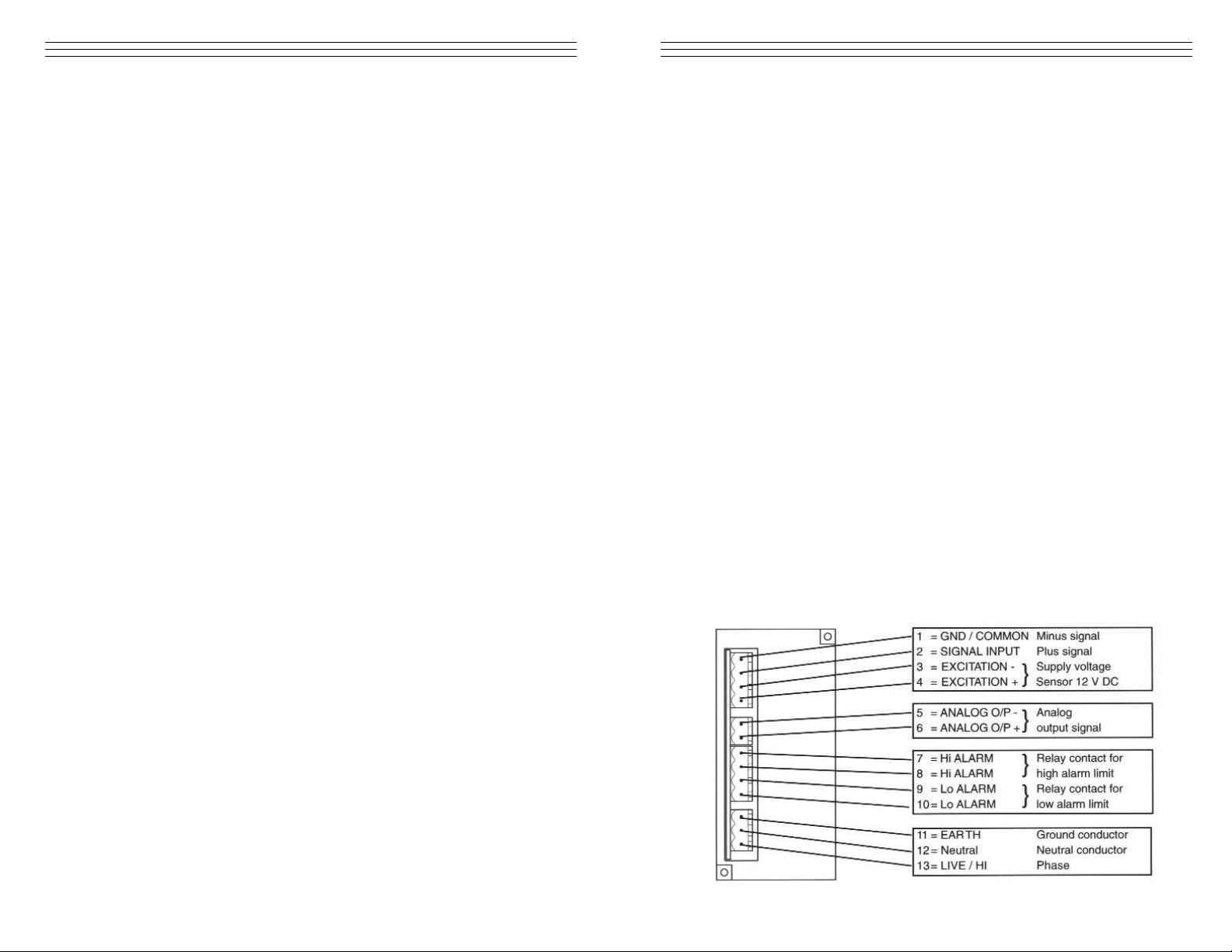
8.0 TECHNICAL INFORMATION
8.2 Pin assignments of connectors
8.1 TD-1-TE Specifications
Digital display 3.5-digit, 7 segment display, height 14.4mm
(with tension range setting
Tension units cN or daN (depending on sensor)
Damping (fg) 1 Hz or 40 Hz (selectable)
Output signal 0–10 VDC / R
LEAD
≥ 1K Ohm
Output voltage +12 VDC (115 V A C)
(sensor)
Power supply 115 V A C
Current Consumption 0.35 A (0.7A)
Relay output 1A / 230 VAC / 30 VDC break contact
Temperature range 1-–45 °C
Air humidity 85% RH, max
Housing Plastic
Dimensions 96 (L) x 48 (W) x 103 (H) mm
Panel cutout 96 (W) x 48 (H) mm
Weight (approx.) 400 g (net) 1000 g (gross)
Page 3
-3-
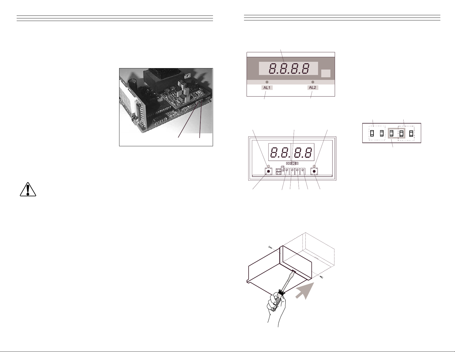
2.0 OVERVIEW OF THE TD-1-TE IND ICAT OR
3.0 REMOVING AND MOUNTING THE FRONT COVER
01 = Digital display
02 = Light emitting diode for low
alarm limit
03 = Light emitting diode for high
alarm limit
04 = Decimal point jumper no jumper
set of decimal point XXXX
05 = Pushbutton for low alarm limit
06 = Potentiometer for low alarm
limit
07 = ZERO potentiometer
08 = GAIN potentiometer
09 = Potentiometer for high alarm
limit
10 = Pushbutton for high alarm limit
Removing: Remove the two screws
Insert a screwdriver with a point width
of 4mm in the slot at the bottom of the
housing and carefully push the front
cover away from the panel in the
direction of the arrow.
Mounting: Carefully push the front
cover onto the housing in the opposite
direction of the arrow.
2. Hang a weight that corresponds to 10% of the tension range (pay attention
to the correct unit of measure) from the measured material, vertically, as
shown in the figure on page 12. (Always use a fresh portion of the
material to be measured.)
3. Adjust the potentiometer (13)
using a screw-driver with a
point width of up to 2mm
until the display of the
voltmeter connected to the
Analog interface reads
0.1 volts
-14-
GAIN Adjustment Procedure
1. Perform a Zero adjustment.
2. Thread the process material through the measuring rollers.
When threading the process material through the rollers, follow the
material path symbol on the front of the sensor. If a force is applied
to the middle sensor roller in the incorrect direction, damage could
result.
NOTE: Since zero and gain adjustments are always performed
statically, the display values may differ under dynamic load.
3. Hang a weight that corresponds to 95% of the tension range (pay
attention to the correct unit of measure) from the measured material,
vertically as shown in the figure on page 12. (Always use a fresh
portion of the material to be measured.)
4. Adjust the potentiometer (14) using a screwdriver (with a point width
of up to 2mm) until the display of the voltmeter connected to the
Analog interface reads 9.5 volts.
Check the setting and repeat the procedure if necessary.
1
2
3
XXX.XX.XXX
WARNING
13
14
42
3
XX.XX
567
8
9
10
Screw
Screw
Page 4

-4-
4.0 SETUP
4.1 Setting the Decimal Point (Refer to the diagrams in Section 2.0)
The decimal point is factory-set to the supplied sensor. If the indicator
unit is supplied without a sensor or after changing to a sensor with a
different tension range, the decimal point jumper (4) must be set to the
sensor's tension range as follows:
1. Remove the front cover as described in Section 3.0.
2. Set the jumper for decimal point display to the desired position (4)
4.2 Setting the Low Alarm Limit (Refer to the diagrams in Section 2.0)
1. Remove the front cover as described in Section 3.0.
2. Connect the TD-1-TE to the power supply and switch on.
3. Press the pushbutton (5) and use a screwdriver with a point width of
2.5 mm to turn the potentiometer (6) to the desired low alarm limit.
Keep the pushbutton (5) depressed while adjusting the pot. At the
same time, the digital display (1) shows the set low alarm limit.
4.3 Setting the High Alarm Limit (Refer to the diagrams in Section 2.0)
1. Remove the front cover as described in Section 3.0.
2. Connect the TD-1-TE to the power supply and switch on.
3. Press the pushbutton (10) and use a screwdriver with a point width
of 2.5 mm to turn the potentiometer (9) to the desired high alarm
limit. Keep the pushbutton (10) depressed while adjusting the pot. At
the same time, the digital display (1) shows the set high alarm limit.
4. Then set the front cover back in place as described in Section 3.0.
4.4 Enabling and Disabling Electronic Damping (Refer to the diagrams
in Section 2.0)
1. The indicator unit is shipped from the factory with the damping
disabled. To enable damping follow this procedure
2. Make sure the TD-1-TE is switched off and all plug connections on
the rear side of the device are disconnected.
-13-
When power is switched on, a voltage of 115 V is applied to the PC
board which is not protected against accidental contact when
removed from the housing. For this reason, calibrating the analog
output may only be carried out by trained electricians whose qualification for such work has been certified in accordance with local
regulations.
2. Connect a voltmeter to the ANALOG interface.
3. Connect the power supply in accordance with the pin assignment of
Section 8.2.
4. Switch on the power to the TD-1-TE.
5. Allow approx. 10 minutes for thermal stabilization of the unit.
ZERO Adjustment Procedure
1. Thread the process material through the measuring rollers, following
the red marking on the front of the sensor.
When threading the process material through the rollers,
follow the material path symbol on the front of the sensor. If a force
is applied to the middle sensor roller in the incorrect direction, damage could result.
NOTE: Since zero and gain adjustments are always performed
statically, the display values may differ under dynamic load.
WARNING
WARNING
Mounting holes 4 x
Material path
symbol
Guide rollers 2x
Measuring
roller
Weight
Page 5

-5-
3. Remove the front cover as
described in Section 3.0
4. Loosen the retaining screw (11) at
the bottom of the housing.
5. Carefully slide out the PC board
from the indicator housing in the
direction of the arrow.
6. Carefully slide the PC board back
into the indicator housing in the
opposite direction of the arrow.
7. Tighten the retaining screw 11 at
the bottom of the housing.
8. Set the front cover back in place
as described in Section 3.0.
Setting the jumpers:
Damping disabled
Damping enabled
Enable or disable electronic
damping with the jumpers at
the top of the PC board.
-12-
7.2 Zero and Gain Adjustments of the ANALOG Interface
If you change the connected sensor or if you want to fine-tune the
Analog interface you need to recalibrate the interface.
Adjustments to the analog output may only be carried out by
trained electricians whose qualification for performing such work
has been certified in accordance with local regulations.
Only sensors which comply with the specifications given in Section
8.3 may be connected. To avoid random noise and malfunctions,
make sure the cable connecting the TD-1-TE with the sensor is not
laid parallel to powerlines or highly loaded signal lines, regardless
of the type of voltage.
1. Remove the front cover following the instructions outlined in
Section 3.0.
2. Loosen the retaining screw
(11) at the bottom of the
housing.
3. Carefully slide out the PC
board from the indicator
housing in the direction of
the arrow.
Preparations for Calibration
1. Connect the TD-1-TE with sensor to be used in accordance with
the pin assignment illustrated in Section 8.2.
Only sensors which comply with the specifications given in Section
8.3 may be connected. To avoid random noise and malfunctions,
make sure the cable connecting the TD-1-TE with the sensor is not
laid parallel to power lines or highly loaded signal lines, regardless
of the type of voltage.
.
WARNING
WARNING
11
WARNING
11
11
Page 6

-6-
5.0 OPERATION
1. Install the sensor at the desired measuring location.
2. Connect the TD-1-TE with the supplied sensor as described Section 8.2..
Only sensors which comply with the specifications given in
Section 8.3 may be connected.
3. Connect the indicator unit with the power supply as described in Section
8.2 If a longer connecting cable should be required to connect the sensor
with the TD-1-TE, note the pin assignment of the sensor's 8-pin connector
indicated in the specifications of the sensor's Operating Instructions.
To avoid random noise and malfunctions, make sure the cable
connecting the TD-1-TE with the sensor is not laid parallel to power
lines or highly loaded signal lines, regardless of the type of voltage.
NOTE: The requirements of the CIE specification are only complied with
if the TD-1-TE is equipped and operated with sensors and connecting
cables supplied by Electromatic Equipment Company. Certification to the
CIE specification does not extend to, and shall be invalid for any other
combination. Under no circumstances shall Electromatic Equipment
Company be held liable for any resulting damage.
4. Switch on the power to the TD-1-TE. Allow approx. 10 minutes
for thermal stabilization.
5. If the material path is other than vertical or if the process material deviates
significantly from the Electromatic calibration material, you need to carry
a zero and gain adjustment before using, as described in Sections 6.1
and 6.2.
6. Thread the process material through the measuring rollers, following the
red marking on the front of the sensor.
7. The digital display will now show the measured line tension.
Process Material
Material Path Symbol
-11-
7.0 ANALOG INTERFACE
The analog interface is provided for customer signal processing or for connecting a line recorder which conforms to the current industrial standard.
Refer to Sections 8.1 and 8.2 for the specifications for the analog interface.
The TD-1-TE can be set to provide a 4-20 mA or a 0-10 VDC analog output
(non-isolated). It is supplied from the factory set for 4-20 mA output. To
configure the TD-1-TE for 0-10 VDC output a series of three jumpers must
be reconfigured into a different arrangement. To do this the internal PC Board
must be removed from the TD-1-TE housing and the small Input Card must
be removed from the PC Board to expose the jumpers. Refer to Section 7.1
The analog output is adjusted using the Analog Output Zero & Gain Pots
which are located on the right side of the PC Board under the Input Card.
The PC Board must be removed from the TD-1-TE housing to perform this
adjustment, but the Input Card does not have to be removed.
7.1 Changing Analog Output Type
To obtain access to the Analog Output
Adjustment Pots the PC Board must be
removed from the TD-1-TE housing.
1. Unplug all connectors on the rear
side of the unit (sensor, power, etc.)
2. Remove the front cover as
performed during calibration.
3. Remove the PC board retaining
screw located at the bottom of
the housing.
4. Carefully slide out the entire
internal assembly.
5. Remove the Input Card by
grasping it by its edges and pulling
straight up. The three jumpers will
be adjacent to the Analog Output
Adjustment Pots
6. Carefully remove all three jumpers
and re-configure them as shown
in the diagram.
WARNING
WARNING
Page 7

-7-
6.0 CALIBRATION
All tension meters are calibrated with standard material—such as polyamidemonofilament (PA)—according to the Electromatic factory procedure; the
material path is vertical. Any difference in process material size and rigidity
from the standard material may cause a deviation of the accuracy.
In 95% of all industrial applications, the Electromatic calibration has been
proven to provide the best results and is used for comparative purposes.
If required, you can also operate the sensors with a material path other than
vertical. Should the process material differ significantly from the
Electromatic calibration material in size, rigidity and shape, we recommend
special calibration using customer-supplied material. In the case of a material
path other than vertical or special calibration using customer-supplied
material, you need to carry out static zero and gain adjustment once again
as described in Sections 6.1 and 6.2.
When threading the process material through the rollers, follow the
material path symbol on the front of the sensor. If a force is applied
to the middle sensor roller in the incorrect direction,
damage could result.
NOTE: Since zero and gain adjustments are always performed statically, the
display values may differ under dynamic load.
-10-
NOTE: Since zero and gain adjustments are always performed
statically, the display values may differ under dynamic load.
3. Hang a weight that corresponds to the tension to be measured (pay
attention to the correct unit of measure) from the measured material,
vertically, as shown in the figure above (Always use a fresh portion
of the material to be measured.)
The tension value on the digital display should be equal to the
value of the suspended weight.
If this procedure shows a deviation beyond the allowable tolerance and
a reliable operation is no longer allowed, the instrument has to be
readjusted, following the directions in Section 6.3.
Guide rollers 2x
Mounting holes 4 x
Material path
symbol
Measuring
roller
Weight
WARNING
Mounting holes 4 x
Material path
symbol
Guide rollers 2x
Measuring
roller
Weight
Page 8

-8-
6.1 Zero Adjustment
Requirements:
• Decimal point set as described in Section 4.0.
• Front cover removed as described in Section 3.0.
• Sensor mounted at measuring location.
Only sensors which comply with the specifications given in Section
8.2 may be connected. To mold random noise and malfunctions,
make sure the cable connecting the TD-1-TE with the sensor is not
laid parallel to power lines or highly loaded signal lines, regardless
of the type of voltage.
NOTE: The requirements of the CIE specification are only complied
with if the TD-1-TE is equipped and operated with sensors and connecting cables supplied by Electromatic Equipment Company. Certification
to the CIE specification does not extend to, and shall be invalid for any
other combination. Under no circumstances shall Electromatic
Equipment Company be held liable for any resulting damage.
Procedure:
1. Connect the TD-1-TE with supplied sensor as shown in Section 8.2
2. Switch on the TD-1-TE and allow approx. 10 minutes for thermal
stabilization of the unit
3. Thread the process material through the measuring rollers, following
the red marking on the front of the sensor.
4. Hang a weight that corresponds to 10 % of the tension range (pay
attention to the correct unit of measure) from the measured material,
vertically as shown on page 7. (Always use a fresh portion of the
material to be measured.)
5. Adjust the potentiometer ZERO (#7, page 3) using a screwdriver
with a point width of up to2 mm until the tension value on the digital
display is equal to the value of the suspended weight.
For example:
Sensor Model TS - 200: Weight 20 cN = Display 20.0 cN
6. Set the front cover back in place as described in Section 3.0.
-9-
6.2 Gain Adjustment
1. Perform a Zero adjustment carried out as described in Section 6.1.
2. Thread the process material through the measuring rollers.
3. Hang a weight that corresponds to 95 % of the tension range (pay
attention to the correct unit of measure) from the measured material,
vertically as shown on page 7. (Always use a fresh portion of the
material to be measured.)
4. Adjust the potentiometer GAIN (#8, page 3) using a screwdriver
(with a point width of up to 2mm until the tension value on the
digital display (#1) is equal to the value of the suspended weight.
For example:
Sensor Model TS - 200: Weight 190 cN = Display 190.0 cN
5. Check the calibration with a fresh portion of the process material and
repeat the adjustments if required, following the directions in
Section 6.0.
6. Set the front cover back in place as described in Section 3.0.
6.3 Checking the Calibration
For general information, refer to Section 6.0.
Requirements:
• Decimal point set as described in Section 4.0.
• Front cover removed as described in Section 3.0.
• Sensor mounted at measuring location.
• TD-1-TE connected with supplied sensor as described in Section 8.2.
Procedure:
1. Switch on the power to the TD-1-TE. Allow Approx. 10 minutes for
thermal stabilization of unit.
2. Thread the process material through the measuring rollers, following
the red marking on the front of the sensor
When threading the process material through the rollers, follow the
material path symbol on the front of the sensor. If a force is applied
to the middle sensor roller in the incorrect direction, damage could
result.
WARNING
WARNING
Page 9

9.0 WARRANTY
ELECTROMATIC Equipment Co., Inc. (ELECTROMATIC) warrants to the original
purchaser that this product is of merchantable quality and confirms in kind and quality with
the descriptions and specifications thereof. Product failure or malfunction arising out of any
defect in workmanship or material in the product existing at the time of delivery thereof
which manifests itself within one year from the sale of such product, shall be remedied by
repair or replacement of such product, at ELECTROMATIC’s option, except where unauthorized repair, disassembly, tampering, abuse or misapplication has taken place, as determined
by ELECTROMATIC. All returns for warranty or non-warranty repairs and/or replacement
must be authorized by ELECTROMATIC, in advance, with all repacking and shipping
expenses to the address below to be borne by the purchaser.
THE FOREGOING WARRANTY IS IN LIEU OF ALL OTHER WARRANTIES,
EXPRESSED OR IMPLIED, INCLUDING BUT NOT LIMITED TO, THE WARRANTY
OF MERCHANTABILITY AND FITNESS FOR ANY PARTICULAR PURPOSE OR
APPLICATION. ELECTROMATIC SHALL NOT BE RESPONSIBLE NOR LIABLE FOR
ANY CONSEQUENTIAL DAMAGE, OF ANY KIND OR NATURE, RESULTING FROM
THE USE OF SUPPLIED EQUIPMENT, WHETHER SUCH DAMAGE OCCURS OR IS
DISCOVERED BEFORE, UPON OR AFTER REPLACEMENT OR REPAIR, AND
WHETHER OR NOT SUCH DAMAGE IS CAUSED BY MANUFACTURER’S OR
SUPPLIER’S NEGLIGENCE WITHIN ONE YEAR FROM INVOICE DATE.
Some State jurisdictions or States do not allow the exclusion or limitation of incidental or
consequential damages, so the above limitation may not apply to you. The duration of any
implied warranty, including, without limitation, fitness for any particular purpose and merchantability with respect to this product, is limited to the duration of the foregoing warranty.
Some states do not allow limitations on how long an implied warranty lasts but, not withstanding, this warranty, in the absence of such limitations, shall extend for one year from the
date of invoice.
ELECTROMATIC Equipment Co., Inc.
600 Oakland Ave. Cedarhurst, NY 11516—USA
Tel: 1-800-645-4330/ Tel: 516-295-4300/ Fax: 516-295-4399
Every precaution has been taken in the preparation of this manual. Electromatic Equipment Co., Inc.,
assumes no responsibility for errors or omissions. Neither is any liability assumed for damages resulting
from the use of information contained herein. Any brand or product names mentioned herein are used for
identification purposes only, and are trademarks or registered trademarks of their respective holders
Page 10

ELECTROMATIC
E Q U I P M E N T C O., I N C.
600 Oakland Ave., Cedarhurst, NY 11516–U.S.A.
TEL: 516-295-4300 • FAX: 516-295-4399
CHECK•LINE
®
INSTRUMENTS
TD-1-TE
WITH TE TENSION SENSORS
Operati n g In str ucti ons
CHECK•LINE
®
BY ELECTROMATIC
xxxxxxxx
 Loading...