

Page 1

NOTES
TABLE OF CONTENTS
1.0 Positioning the instrument ……………………………………………. 2
2.0 Calibration curves …………………………………………………….. 2
3.0 Description of definitons ……………………………………………… 3
4.0 Application range ……………………………………………………… 4
5.0 Design of the device ………………………………………………….. 4
6.0 Menu level overview ………………………………………………….. 5
7.0 Operating the instrument …………………………………………….. 6
8.0 Transfer saved data to the PC ………………………………………. 7
9.0 Print saved data ………………………………………………………. 8
10.0 Single-point adjustment with 50% humidity standard …………….. 9
11.0 Offset adjustment ……………………………………………………… 11
12.0 Reset to factory calibration …………………………………………… 12
13.0 Conditioning of the sensor ……………………………………………. 12
14.0 Care instructions ………………………………………………………. 13
15.0 Changing the batteries ……………………………………………….. 13
16.0 Exemprion from liability ………………………………………………. 14
17.0 Optional accessories …………………………………………………. 14
18.0 Technical data ……………………………………………………….... 15
19.0 Common reasons for incorrect measurements ……………………. 16
20.0 Warranty ……………………………………………………………….. 17
Electromatic Equipment Co., Inc.
-20-
Electromatic Equipment Co., Inc.
-1-
Page 2
1.0 POSITIONING THE INSTRUMENT
Insert the sword-sensor into the stack for only approx. 10 cm, and push it a few
more centimetres into the stack every 10 seconds. Let your RH6 adequately adjust
to the material (at least 5 minutes) before you start to measure, particularly when
the material pile was stored at a different temperature than the device. When
removing the sword-shaped sensor please ensure that there is no up or down
movement, because this could deform the sensor. For heavy stacks and rolls please
use the optionally available sword sensor holder and the tool for removing the sword
sensor holder.
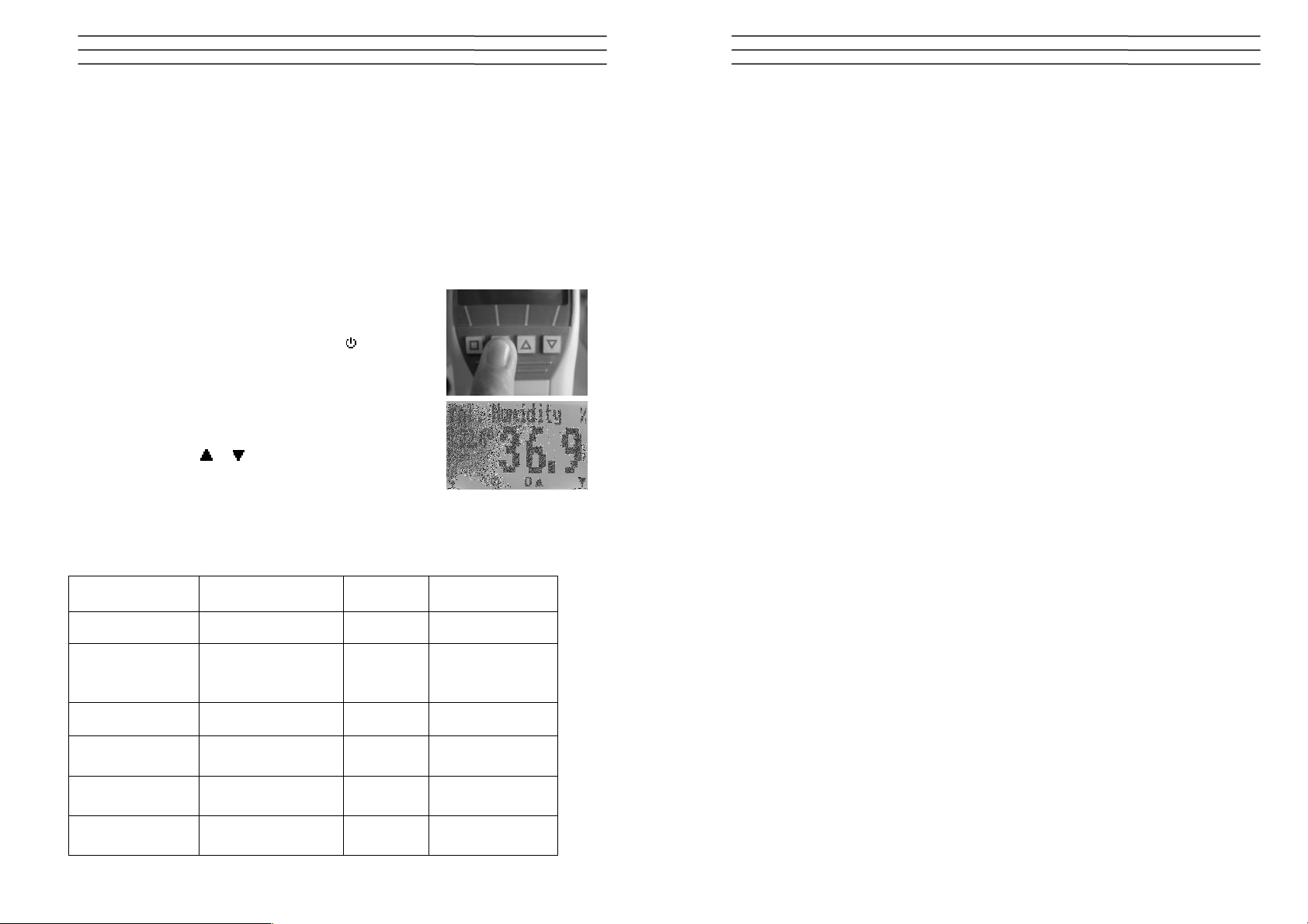
1.1 Measurement
To switch on the instrument, press the
key for 3
seconds.
After showing the logo, the measuring window opens and
the current temperature and moisture value is displayed.
In the type selection menu the calibration curves can be
changed by pressing
or . The calibration curves saved
in the device can be found in the following list.
2.0 CALIBRATION CURVES
calibration curve description unit measuring range
NOTES
rel. humidity rel. humidity of air %rh 0 to 100%
55 to +60°C
dew point dew point °C resp. °F
resp.
-67 to 140°F
abs. humidity abs. humidity of air g/m³ 0 to 130 g/m³
EMC wood
aH Kraftliner %
aH Testliner %
equilibrium moisture
content of wood
absolute moisture
Kraftliner paper
absolute moisture
Testliner paper
Electromatic Equipment Co., Inc.
-2-
%EMC
% 5 to 15%
% 3 to 12,2%
2 to 30%
(wood moisture)
Electromatic Equipment Co., Inc.
-19-
Page 3

NOTES
3.0 DESCRIPTION OF DEFINITIONS
Relative air humidity: indicates the relation between the current water vapour
pressure and the maximal possible water vapour pressure (called saturation vapour
pressure).
The relative humidity shows the degree the air is saturated with water vapour. For
example:
50% relative humidity indicates that at the current temperature and the current
pressure the air is saturated with water vapour for half of its value, 100 % relative
humidity means that the air is totally saturated. When the air has more than 100 %
of relative humidity, the excessive moisture would condense or form fog.
Absolute humidity: shows the contained amount of water in gramme per cubic
metre of air. The absolute humidity is a direct degree for the amount of water vapour
contained in a certain air volume. It shows how much moisture can maximally
condense or how much water has to be evaporated to receive a certain desired air
humidity.
Dew point temperature: The dew point indicates the temperature that the not
completely saturated air has to reach in order to be completely saturated with water
vapour. If the room with the current relative humidity is cooled down to the dew point
temperature, the water vapour begins to condense.
EMC wood: shows the equilibrium moisture content of wood (for timber stored
under these conditions) in % moisture content of wood and the temperature in the
selected unit (°C or °F).
aH kraftliner: shows the equilibrium moisture content of kraftiner paper (for paper
stored under these conditions) in % moisture content and the temperature in the
selected unit (°C or °F).
aH testliner: shows the equilibrium moisture content of testliner paper (for paper
stored under these conditions) in % moisture content and the temperature in the
selected unit (°C or °F).
empty curves: can be used to calibrate some special products
Electromatic Equipment Co., Inc.
-18-
Electromatic Equipment Co., Inc.
-3-
Page 4

4.0 APPLICATION RANGE
Within the normal application range (normal range) the accuracy of the device is as
indicated. A long-term application beyond the normal application range (max.
range), particularly at an air humidity of more than 80%, can lead to higher
measuring errors (+3% after 60 hours). Back in the normal application range, the
sensor will return to the indicated accuracy automatically.
5.0 DESIGN OF THE DEVICE
USB interface
air humidity and
temperature sensor
calibration curve
temperature
measuring value
ON/OFF button
20.0 WARRANTY
Electromatic Equipment Co., Inc. (Electromatic) warrants to the original purchaser
that this product is of merchantable quality and confirms in kind and quality with the
descriptions and specifications thereof. Product failure or malfunction arising out of
any defect in workmanship or material in the product existing at the time of delivery
thereof which manifests itself within one year from the sale of such product, shall be
remedied by repair or replacement of such product, at Electromatic’s option, except
where unauthorized repair, disassembly, tampering, abuse or misapplication has
taken place, as determined by Electromatic. All returns for warranty or non-warranty
repairs and/or replacement must be authorized by Electromatic, in advance, with all
repacking and shipping expenses to the address below to be borne by the
purchaser.
THE FOREGOING WARRANTY’S IN LIEU OF ALL OTHER WARRANTIES,
EXPRESSED OR IMPLIED, INCLUDING BUT NOT LIMITED TO, THE
WARRANTY OF MERCHANTABILITY AND FITNESS FOR ANY PARTICULAR
PURPOSE OR APPLICATION. ELECTROMATIC SHALL NOT BE RESPONSIBLE
NOR LIABLE FOR ANY CONSEQUENTIAL DAMAGE, OF ANY KIND OR
NATURE, RESULTING FROM THE USE OF SUPPLIED EQUIPMENT, WHETHER
SUCH DAMAGE OCCURS OR IS DISCOVERED BEFORE, UPON OR AFTER
REPLACEMENT OR REPAIR, AND WHETHER OR NOT SUCH DAMAGE IS
CAUSED BY MANUFACTURER’S OR SUPPLIER’S NEGLIGENCE WITHIN ONE
YEAR FROM INVOICE DATE.
Some State jurisdictions or States do not allow the exclusion or limitation of
incidental or consequential damages, so the above limitation may not apply to you.
The duration of any implied warranty, including, without limitation, fitness for any
particular purpose and merchantability with respect to this product, is limited to the
duration of the foregoing warranty. Some states do not allow limitations on how long
an implied warranty lasts but, not withstanding, this warranty, in the absence of such
limitations, shall extend for one year from the date of invoice.
Electromatic Equipment Co., Inc.
600 Oakland Ave. Cedarhurst, NY 11516 - USA
Tel: 1-800-645-7330 / Tel: 516-295-4300 / Fax: 516-295-4399
Every precaution has been taken in the preparation of this manual. Electromatic assumes no
responsibility for errors or omissions. Neither is any liability assumed for damages resulting
from the use of information contained herein. Any brand or product names mentioned herein
are used for identification purposes only, and are trademarks or registered trademarks of their
respective holders.
Electromatic Equipment Co., Inc.
-4-
Electromatic Equipment Co., Inc.
-17-
Page 5

19.0 COMMON REASONS FOR INCORRECT MEASUREMENTS
Keypad symbols
• Sunlight or other sources of heat or cold that doesn´t correspond to the
surrounding temperature
• Dripping or sprayed water
• Irreversible damage of the sensor due to aggressive gases
• Danger of condensation because of changing temperature
• Polluted moisture sensor
• Foreign objects on the sensor
• Measuring errors due to too short conditioning
To demonstrate the importance of temperature adjustment, the table below shows
measuring errors due to a temperature difference of only 1°C / 1.8°F between the
measuring instrument and the substance to be measured at different ambient
temperatures.
10°C (50°F) 20°C (68°F) 30°C (86°F)
10%r.h. ±0,7% ±0,6% ±0,6%
50%r.h. ±3,5% ±3,2% ±3,0%
90%r.h. ±6,3% ±5,7% ±5,4%
At room temperature (20°C / 68°F) and assumed paper moisture value of 50% r.h. a
deviation of 1°C / 1.8°F between the measuring sens or and the substance to be
measured results in a measuring error of 3.2% r.h. A deviation of 3°C / 5.4°F would
result in a measuring error of over 10%.
Further examples can be found in the Mollier h-x diagram.
6.0 MENU LEVEL OVERVIEW
Edit Logs
Manual Logs
Auto Logs
Clear Logs
Print Logs
Last Logs
All Logs
Clear Logs
Send Logs
Manual Logs
Auto Logs
Clear Logs
Type selection menu
Next calibration curve
Previous calibration curve
Power off
Store menu
Show last log
Store new log
Power off
Main menu
Switch lower
Switch upper
Open this menu / enter
Options
Date / Time
Datalog Time
Language
Unlock
°C / °F
User level
BL On Time
Auto Off Time
Materialcalib.
Adjust
Password
Reset
Status
Measuring window:
Rolling Menu
Power ON / OFF
Switch upper
Switch lower
Save
Hold
Autolog
Watch saved data
Enter suppliers
data
Menu:
Enter
Switch upper
Switch lower
Exit
Enter numbers
Enter letters
Next or right
Left
Yes
No
Shift
Electromatic Equipment Co., Inc.
-16-
Electromatic Equipment Co., Inc.
-5-
Page 6

7.0 OPERATING THE INSTRUMENT
Switching on: Press
for 3 seconds.
Changing the calibration curve:
or .
Setting the time: 2 times
- Options – Date / Time
Set date and time using the button , according to the format indicated
(JJ.MM.TT). After entering the year, press the button
for entering the month and
again for entering the day. For changing from date to time also press the button
. After finishing, press OK for saving the entered data.
Datalog: Select your desired interval in the menu Options – Log Time using the
arrow keys, and confirm by pressing OK. Now in the store menu appears the
symbol
. By pressing this symbol you can activate the AutoLog.
Info: In order to save battery power the device switches off automatically at a
log interval of 1 minute or longer, and activates again for saving the logs!
For completing the AutoLog, switch on the device (if necessary) and press the
button. If you want to add supplier´s data please press the button. Supplier´s data
can also be entered on the PC subsequently.
Switching on the display lighting: Press the
key briefly; the display lighting
switches off automatically after approx. 20 seconds. Pressing any key activates the
display lighting again, and the period for switching off again is prolonged to four
minutes (The display lighting time can be modified in menu level Options – BL On
Time).
Switching off: Press the
key for 5 seconds. The instrument switches off after
releasing the key. The instrument switches off automatically after approx. four
minutes. (The turn-off time can be modified in menu level Options – Auto Off Time).
Other instrument functions – overview
• Manual saving of single measuring values in a measurement series
• Display of measuring series and measuring values directly on the instrument
• Printing the saved measuring series (only with PC interface and printer)
• Transfer and saving of measuring series on a PC (only with PC interface)
• Automatic single-point adjustment at 50% humidity standard
• Selection of menu language (DE, EN, FR, IT, ES, RU)
• Display of temperature in Celsius or Fahrenheit
18.0 TECHNICAL DATA
Measurement Meas. Range / Resolution / Accuracy
rel. humidity 0 to 100% rh / 0,1%
calibration 10 to 90% / ±1,5% rh (at 25°C)
temperature °C -10 to +60°C / 0,1°C / ±0,3°C (at 25°C)
temperature °F 14 to 140°F / 0,3°F / ±0,5°F (at 77°F)
dew point °C -55 to +60°C / 0,1°C
dew point °F -67 to 140°F / 0,3°F
Operating temp. range -10°C to 60°C / 14 to 140°F
Storage temp -20°C to 60°C / -4 to 140°F
Temperature compensation Automatic
Data storage approx. 10.000 measuring values
Menu languages English, German, French, Italian, Spanish,
Power supply 4 pcs. 1.5Volt AA Alkaline batteries
(for approx. 1800 measurements)
Auto Off time after approx. 4 minutes
Power consumption 30 mA (with display lighting)
Display 128 x 64 matrix display with LED backlighting
Dimensions housing 145 x 63 x 29mm
Dimensions sword sensor 295 x 20 x 4mm
Weight approx. 260g (incl. batteries)
Protection class IP 40
Scope of supply wooden case, rubber protection cover, 4 pcs.
1.5 Volt AA Alkaline batteries, user manual
Russian
Electromatic Equipment Co., Inc.
-6-
Electromatic Equipment Co., Inc.
-15-
Page 7

16.0 EXEMPTION FROM LIABILITY
For miss-readings and wrong measurements and of this resulting damage we refuse
any liability. This is a device for quick determination of moisture. The moisture
depends on multiple conditions and multiple materials. Therefore we recommend a
plausibility check of the measuring results. Each device includes a serial number
and the guarantee stamp. If those are broken, no claims for guarantee can be
made.
If the battery symbol appears in the measuring window
resp. if a critical charge of battery is shown in the status,
the batteries have to be changed IMMEDIATELY. If you do
not use your device for a longer period, remove the
batteries. For eventual resulting damages we cannot
provide any warranty.
In case of a faulty device, please contact Checkline
Europe.
17.0 OPTIONAL ACCESSORIES:
• PC interface for printing saved data on mobile printer and/or for transfer of
data to a PC incl. LogMemorizer
• LogMemorizer measuring data recording and analysing software for
Windows® PCs: databank based recording of data, direct analysis of
measuring data in the programme, various export functions
• Mobile printer – thermo printer, runs by battery
• Sword sensor holder for protection of sword sensor in heavy paper piles
• Tool for removing sword sensor holder from heavy paper piles
• Calibration equipment and calibration ampoules for checking instruments
of the RHx series by the customer itself
8.0 TRANSFER SAVED DATA TO THE PC
To send your saved logs to the PC, connect the RH6
device to your PC using the USB cable that was delivered
with your device. Carefully loose the protection cap on your
RH6 and plug in the USB mini B connector. The bigger
connector has to be connected to a USB slot on your PC.
Start the LogMemorizer software on your PC and switch on
your RH6.
The data transfer can be started on your RH6 or on the
software:
Starting the data transfer on the RH6:
Press the
the right). Then choose „Send Logs“ and confirm by
pressing the
confirm with
PC.
Starting the data transfer on the PC:
Press the button „remote control“ in the LogMemorizer
software. A drop-down menu with several options opens
(see image).
For transferring the data you can select „Import last
manual log“ (the last saved measuring series is
transferred) or „Import all manual logs“ (all saved logs are
transferred).
If you click on one of these menu items, the transfer starts
immediately.
For the basic adjustments of the software please look
through the instructions on the LogMemorizer CD.
key until you reach the menu (see image on
key. Now choose „Manual Logs“ and
again. All saved logs will be sent to your
Electromatic Equipment Co., Inc.
-14-
Electromatic Equipment Co., Inc.
-7-
Page 8

9.0 PRINT SAVED DATA
To print your saved data, connect the device to the printer
using the printer cable that was delivered with your
device. Carefully loose the protection cap on the RH6. At
first plug in the side of the connector with the close plastic
casing at the RH6. Then switch on the device.
Not till then the other side of the cable has to be plugged
in at the printer. Switch on the printer by pressing
. Now
the green LED is blinking. If it does not blink, please
change the batteries and try again.
Press the
button at your RH6 until you reach the menu
(see image on the right). Choose „Print Logs“ and confirm
by pressing
.
Now you can select if you want to print the last saved
measuring series or all saved measuring series (logs).
Confirm by pressing
again. The selected logs are
printed out now.
To save paper, please think of clearing the data storage
regularly.
14.0 CARE INSTRUCTIONS
Do not drop the instrument or expose it to excessive temperatures. The instrument
is not waterproof. Do not immerse the sensor in liquid.
The intervals for checking the instrument depend on your operational demands and
the required level of accuracy. In general the drift of the sensor according to the
degree of use (constant humidity or use within the whole moisture measuring range)
is beneath 0.5 % per year. You can check RH6 instrument by yourself using the
calibration equipment (see optional accessories). For a fee, Checkline Europe can
also carry out a calibration at their factory. On demand you will also receive a
calibration certificate.
15.0 CHANGING THE BATTERIES
First of all remove the rubber protection cover. For that, hold the rubber protection
cover at the upper side and pull it over. If your RH6 is provided with an USB port,
you have to remove the protection cap before. Press with your finger onto the arrow
of the battery cap and pull it back.
Remove the empty batteries. Put four new 1.5 Volt AA Alkaline batteries in the
device. Make sure that the position of the battery poles is correct. Press down the
batteries and close the cap.
Electromatic Equipment Co., Inc.
-8-
Electromatic Equipment Co., Inc.
-13-
Page 9

12.0 RESET TO FACTORY CALIBRATION
1. Press the
2. Select the menu item Reset using the button and confirm by pressing .
button two times to reach the menu point Options.
3. Enter the superuser password using the buttons resp. and confirm by
pressing
• The query “reset?” appears on the display.
4. Press the button for resetting the device to the factory calibration.
.
• The software reloads the factory calibration data and reboots the device.
This will need about 15 to 20 seconds.
5. Pressing the button you can exit without any changes.
13.0 CONDITIONING OF THE SENSOR
The conditioning of the sensor (time until the device shows the actual measuring
value) depends on several parameters. The parameter responsible for the highest
measuring error is a temperature discrepancy between the sensors resp. the whole
measuring instrument and the material to measure resp. the air. In order to fasten
the conditioning, the following proceedings are possible:
Spaced insertion of the sword sensor
o Insert the sword-sensor into the stack for only approx. 10 cm, and push it a few
more centimetres into the stack every 10 seconds.
In case of a high temperature difference repeat this action – if necessary several
times!
o If you use the sword sensor holder, please ensure that both the sword sensor
and the sword sensor holder are adjusted to the surrounding temperature of the
material.
In this case insert the sword sensor holder at frequent intervals and leave the
sword sensor in the sword sensor holder for an appropriate period.
10.0 SINGLE-POINT ADJUSTMENT WITH 50% HUMIDITY STANDARD
For the adjustment the appropriate calibration equipment as well as calibration
ampoules resp. humidity standards of 50 % r.h. are required.
10.1 Proceedings
Preparation
To ensure as good as possible inspection results it is
essential that the measuring device, the calibration
equipment and the calibration ampoules have
approximately the same temperature. This
temperature has to be between 20°C and 26°C.
The best way to ensure the same temperature of the
different components is to store all components
together in a room with only small temperature
fluctuations minimum over night – better for 24 hours.
Components of calibration equipment
In this image you can see the components of the
calibration equipment and a calibration ampoule with
humidity standard.
10.2 Assembly of calibration equipment
1. Put in the first gasket ring in the upper part of the calibration device.
2. Push in the sword sensor in the upper part as shown in the picture.
3. Now put the second gasket ring into the upper part.
4. Lay in the textile pad in the bottom part of the calibration device, and pour the
humidity standard carefully at the textile pad.
Electromatic Equipment Co., Inc.
-12-
Electromatic Equipment Co., Inc.
-9-
Page 10

5. Now put the third gasket ring into the bottom part.
6. Fit the metal ring on the third gasket.
7. Take the upper part with the RH6 and attach these carefully at the bottom part of
the calibration device.
8. Pick up the RH6 together with the calibration device STRAIGHT and DON´T
TURN IT AROUND. Screw it up like shown in the picture.
Then put the RH6 with the calibration device down on a table carefully and proceed
as follows:
Conditioning the sensor
To achieve best results, let the sensor adjust for two hours. The temperature has
to be between 20°C and 26°C.
If the shown measuring value differs more than the factory tolerance (1.5% r.h.), we
recommend to carry out a recalibration as follows.
11.0 OFFSET ADJUSTMENT
1. Leave the measuring device in the calibration equipment, and switch it on.
2. Press the Rolling Menu button until you reach the main menu.
3. Select the menu item Options by pressing the button and confirm by pressing
.
4. Navigate to Setting using the button and confirm by pressing again.
5. Enter the superuser password using the buttons resp. and confirm by
pressing
• The superuser password after consignment is the serial number of the
6. A query if a setting is desired appears. Confirm by
pressing
7. Wait until the bar has risen completely. The device
adjusts by itself and automatically jumps back to the
measuring window. The adjustment is completed
now.
8. Check the result before you remove the device from
the calibration equipment. Depending on the
temperature the display should show a humidity
around 50% now.
If you made a mistake during the setting, you can reset to the factory calibration as
follows:
.
device, shown on the display after switching on the device or in menu item
Status.
.
Electromatic Equipment Co., Inc.
-10-
Electromatic Equipment Co., Inc.
-11-
Page 11

PAPER MOISTURE METER
RH6
OPERATING INSTRUCTIONS
 Loading...