

Page 1

– 1 –
TABLE OF CONTENTS
01.0 Introduction . . . . . . . . . . . . . . . . . . . . . . . . . . . . . . . . . . . . . . . . . . . . . . . . . 02
02.0 Contents . . . . . . . . . . . . . . . . . . . . . . . . . . . . . . . . . . . . . . . . . . . . . . . . . 03
03.0 Overview . . . . . . . . . . . . . . . . . . . . . . . . . . . . . . . . . . . . . . . . . . . . . . . . . 04
3.1 Front side
3.2 Back side
3.3 LCD display
04.0 Charging The Battery . . . . . . . . . . . . . . . . . . . . . . . . . . . . . . . . . . . . . . . . . 06
4.1 Battery Charger (AC-Adapter) Set-up
05.0 Operating From AC Power . . . . . . . . . . . . . . . . . . . . . . . . . . . . . . . . . . . . . 07
06.0 Information On Battery Management . . . . . . . . . . . . . . . . . . . . . . . . . . . . . 08
7.0 Operating the PK2X . . . . . . . . . . . . . . . . . . . . . . . . . . . . . . . . . . . . . . . . . . . 09
08.0 External Triggering . . . . . . . . . . . . . . . . . . . . . . . . . . . . . . . . . . . . . . . . . . . 10
09.0 Replacing The Flash Tube . . . . . . . . . . . . . . . . . . . . . . . . . . . . . . . . . . . . . 11
10.0 Error Messages . . . . . . . . . . . . . . . . . . . . . . . . . . . . . . . . . . . . . . . . . . . . . . 12
11.0 Maintenance . . . . . . . . . . . . . . . . . . . . . . . . . . . . . . . . . . . . . . . . . . . . . . . . 13
12.0 Slowing Down The Motion . . . . . . . . . . . . . . . . . . . . . . . . . . . . . . . . . . . . 14
13.0 Harmonics . . . . . . . . . . . . . . . . . . . . . . . . . . . . . . . . . . . . . . . . . . . . . . . . . 15
14.0 Determining An Object’s True RPM . . . . . . . . . . . . . . . . . . . . . . . . . . . . . . 16
15.0 Optional Accessories . . . . . . . . . . . . . . . . . . . . . . . . . . . . . . . . . . . . . . . . . . 21
16.0 Specifications . . . . . . . . . . . . . . . . . . . . . . . . . . . . . . . . . . . . . . . . . . . . . . . . 22
17.0 Safety Precautions . . . . . . . . . . . . . . . . . . . . . . . . . . . . . . . . . . . . . . . . . . . . 23
18.0 Warranty . . . . . . . . . . . . . . . . . . . . . . . . . . . . . . . . . . . . . . . . . . . . . . . . . 24
— Please Note —
The internal battery fully recharges in about two hours.
However, for best results, please charge the battery
for at least three hours prior to its first use.
– 24 –
18.0 WARRANTY
The manufacturer warrants to the original purchaser that this product is of merchantable quality and confirms in kind and quality with the descriptions and specifications thereof. Product failure or malfunction arising out of any defect in workmanship
or material in the product existing at the time of delivery thereof which manifests itself
within one year from the sale of such product, shall be remedied by repair or replacement of such product, at the manufacturer’s option, except where unauthorized repair,
disassembly, tampering, abuse or misapplication has taken place, as determined by the
manufacturer. All returns for warranty or non-warranty repairs and/or replacement
must be authorized by the manufacturer, in advance, with all repacking and shipping
expenses to the address below to be borne by the purchaser.
THE FOREGOING WARRANTY IS IN LIEU OF ALL OTHER WARRANTIES,
EXPRESSED OR IMPLIED, INCLUDING BUT NOT LIMITED TO, THE WARRANTY OF MERCHANTABILITY AND FITNESS FOR ANY PARTICULAR
PURPOSE OR APPLICATION. ELECTROMATIC SHALL NOT BE RESPONSIBLE
NOR LIABLE FOR ANY CONSEQUENTIAL DAMAGE, OF ANY KIND OR
NATURE, RESULTING FROM THE USE OF SUPPLIED EQUIPMENT, WHETHER
SUCH DAMAGE OCCURS OR IS DISCOVERED BEFORE, UPON OR AFTER
REPLACEMENT OR REPAIR, AND WHETHER OR NOT SUCH DAMAGE IS
CAUSED BY MANUFACTURER’S OR SUPPLIER’S NEGLIGENCE WITHIN
ONE YEAR FROM INVOICE DATE.
Some State jurisdictions or States do not allow the exclusion or limitation of incidental
or consequential damages, so the above limitation may not apply to you. The duration
of any implied warranty, including, without limitation, fitness for any particular purpose and merchantability with respect to this product, is limited to the duration of
the foregoing warranty. Some states do not allow limitations on how long an implied
warranty lasts but, not withstanding, this warranty, in the absence of such limitations,
shall extend for one year from the date of invoice.
Every precaution has been taken in the preparation of this manual. The manufacturer, assumes no responsibility
for errors or omissions. Neither is any liability assumed for damages resulting from the use of information contained herein. Any brand or product names mentioned herein are used for identification purposes only, and are
trademarks or registered trademarks of their respective holders.
Page 2

– 2 –
1.0 INTRODUCTION
Congratulations on your purchase of a PK2X Series portable stroboscope.
You can use the Pocket-Strobe in a variety of industrial, laboratory, R&D and
academic environments.
Most commonly, the Pocket-Strobe is used to make objects which are moving at high
speeds appear to be moving in slow motion. When this occurs, you can then safely
and easily analyze their motion, check for proper registration, determine sources of
unwanted vibration, etc.
Also, you can use the Pocket-Strobe to apparently “freeze” an object’s movement.
Without making contact, you can accurately measure the object’s rotational speed
or reciprocation rate.
Unlike other portable stroboscopes, the Pocket-Strobe takes only one hand to
operate—and because it is the world’s smallest industrial stroboscope—it is very
convenient and portable.
Typical applications include use with:
■ High speed assembly lines, conveyor systems, bottling operations, etc.
■ Printing presses and cloth looms
■ Motors, fans, pumps and turbines
■ Calibration and inspection equipment
■ Monitoring laboratory & research applications
Models Available
■ PK2X: operates from Internal Rechargeable Battery or AC-Power.
■ PK2X-OT: same as above but includes optional external trigger output
■ PK2X-AC: supplied without internal battery for use with AC-Power ONLY.
— Caution —
Although objects may appear to be moving slowly or frozen,
NEVER touch any rotating or reciprocating element during testing.
– 23 –
17.0 SAFETY PRECAUTIONS
WARNING: Stroboscopes give the illusion of stopped motion.
Do not touch the machine or object being observed.
The use of stroboscopes may induce an epileptic seizure in
those persons predisposed to this type of attack.
Explosion hazard. Do not use this product in the presence
of an explosive environment.
CAUTION: Do not use this product in wet or condensating environments.
Do not allow liquids or metallic objects to enter into the
ventilation holes.
Wear adequate eye protection when using this product.
Failure to do so could result in serious injury.
NOTICE: The Pocket-Strobe is designed for battery operation only.
Do not operate the instrument while it is recharging. Failure
to do so will damage the unit and void its warranty.
Recharge the battery using only the original battery charger supplied
with the PK2X.
DANGER HIGH VOLTAGE!
To reduce risk of an electronic shock, do not open the Pocket-Strobe.
To replace the flash tube, refer to the section entitled “Replacing the
Flash Tube.” There are no user-serviceable parts inside.
Page 3
– 3 –
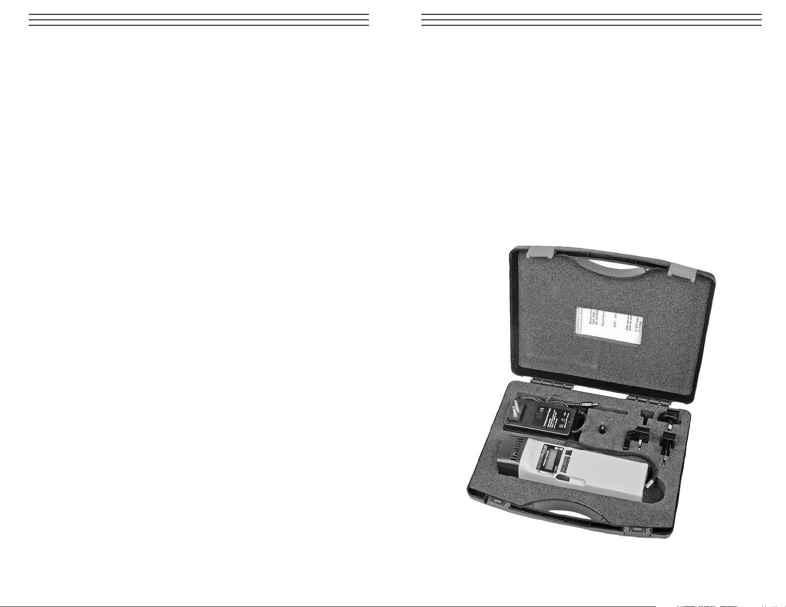
2.0 CONTENTS
Your Pocket-Strobe portable stroboscope comes with the following items:
■ PK2X, PK2X-OT, PK2X-AC Stroboscope
■ Universal AC-Adapter/Charger (100–240 VAC)
■ External Triggering Jack
■ Carrying Case
■ Traceable Calibration Certificate
■ Instruction Manual
– 22 –
16.0 SPECIFICATIONS
Flash Range 30 – 12,500 FPM
Flash Brightness 1200 Lux (8"/20cm distance @ 4500 fpm)
Accuracy ± 0.01% over entire range +1 LSD ± 0.04 Hz
Resolution ±1 FPM over entire range
Display 5-digit LCD
Display Update 0.5 seconds
Flash Energy 170 mJ
Flash Duration < 9 µs
Flash Tube Life 200 million flashes (at 6,000 fpm)
Flash Color Temp 6,000K – 6500K
External Trigger 0-5 volt, DTL/TTL compatible 1/8" jack
Optional Trigger Signal 0-5 volt, DTL/TTL compatible 1/8" jack
Output
(PK2X-OT Only)
Operating Time
Battery,
2 hours
AC-Power
, continuous
Battery Type Lithium Ion (Li-Ion)
Battery Charger
AC Power Required
, 100-240 VAC, 50/60 Hz
DC-Output
, 9 VDC @ 2000 mA max
Charging Time,
4-5 hours
Overcharge Protection Yes
CE Certification Yes
Weight 0.9 lbs (415 grams) including battery
Housing Material High Impact ABS Plastic
Reflector Material Aluminum
Tripod Mount 1/4-20, female insert
Operating Temp. 32 to 104° F (0 to 40° C)
Dimensions 9–3/4" x 2–3/4" x 1–3/4"
(240 x 65 x 40 mm)
Warranty 1 year
Page 4
– 4 –
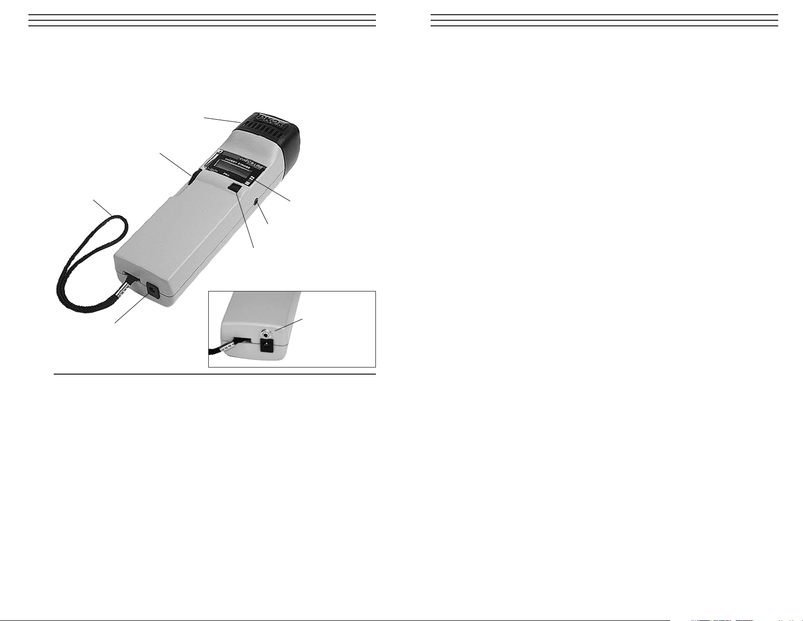
3.0 OVERVIEW
3.1 Front Side
Lens/Bezel Assembly Removed for flash tube replacement.
LCD Display Shows flash rate, low battery indicator and
error messages.
Flash Rate Adjustment Adjusts the flash rate. The speed with which the flash
Knob rate changes is controlled by how quickly the knob is
rotated.
Quick rotation = flash rate changes in large increments.
Slow rotation = flash rate changes in small increments.
Hand Strap Used as wrist trap (if desired).
External Trigger INPUT Used for control of flash rate via external sensor
or controller.
On/Off Switch Turns on power and flashing.
DC-Input Jack for Used to recharge internal battery
AC-Adapter/Charger or operate via AC-Power.
Flash Rate Adjustment Knob
Lens / Bezel Assembly
Hand Strap
On / Off Switch
LCD Display
DC-Input for AC-Adapter / Charger
External Trigger INPUT
Output Trigger
OT Model only
– 21 –
15.0 OPTIONAL & REPLACEMENT ACCESSORIES
PK2X-TBE Spare Xenon flash tube for PK2X (different tube then PK1 or PK2).
PK2X-BAT Replacement Lithium Battery Pack for PK2X.
. (Requires minor soldering for replacement.)
PK2X-AC-BC Replacement Universal AC-Adapter/Charger for PK2X and PK2X-AC
(100–240 VAC, worldwide use).
PK2-HLT Padded-vinyl & leather belt-clip holster.
PK2-PHONO Connection jack for external trigger input or optional trigger output
signal
PK2-TRI Tripod for PK2X.
PK2-BNC External Trigger Cable, 6 feet in length, 1/8" to BNC male.
PK2-8M External Trigger Cable, 6 feet in length, 1/8" male to 1/8" male.
Page 5

– 5 –
Bezel Screw:
Remove this
screw to release the bezel as
needed when replacing flash
tube.
1
/4-20 Threaded Insert:
Used
when fix-mounting strobe on
optional tripod, articulating
arm or other mounting fixture,
External Trigger Indicator:
Used when
external sensor is connected, controlling
the flash rate via trigger input rate.
3.2 Back Side
3.3 LCD Display
Flash Rate # or Error Message
Low Battery Indicator
– 20 –
Helpful Hints
■ The most commonly used formulas are indicated by an asterisk.
■ The values for “X,” “Y” and “Z” are taken in descending order. For example,
the value for “X” is greater than the value for “Y”
■ The values are for successive singular harmonic images. Do not use
multiple images.
■ If two points are recorded, equation (1 Y gives only approximate results.
Equations (2) with (4) and (3) with (5) are more precise, but error can be
introduced due to the rounding.
■ If three points are found, Equation (6) is the most commonly-used formula.
■ For completeness, equations (9) through (21) offer mathematical derivations
and condensed versions of Equation (6). Also included are the formulas for
calculating Sx, Sy and Sz.
Page 6

– 6 –
4.0 CHARGING THE BATTERY (BATTERY MODELS ONLY)
Charge the battery before first use or whenever the Low Battery Indicator is shown.
The Low Batter Indicator can be flashing on/off or remain on, with the following
explanation for each condition:
LO BAT continuously lit - Approximately 6 minutes of operating time remain
LO BAT flashing on/off - Operation will stop momentarily
Plug the Charger/AC-Adapter into and appropriate AC output, selecting and installing
the appropriate plug adapter for the country of use (N. America, Europe, UK and
Australia plug-in adapter provided). Refer to Charger Set-up below. Plug the other end
of the charger (A) into the DC-Input receptacle located in the bottom of the handle on
the strobe housing (refer to Section 3.1, page 4)
After insertion into the AC power outlet, the Red LED will turn on (upper left side of
the charger housing) indicating that the AC-Adapter/Charger is powered and operating
properly. The battery will now be in the process of recharging. A full recharge cycle
will take about 4-5 hours. There is no specific indication when charging is completed,
however you can not overcharge the battery.
NOTE: It is safe to operate the strobe while it is plugged into the charger.
If the strobe is operated while being recharged, the complete charging cycle will be
extended beyond the typical 4-5 hours, as most of the power is being used to operate
the strobe and only a small portion is being used to recharge the battery.
4.1 Battery Charger (AC-Adapter) Set-up
When first using the battery charger, select the appropriate plug connector for
use in the AC power outlet (several styles provided) and align the holes in the
rear side of the plug connector “B” with the pins in the receptacle in the battery
charger body “C” and push. When properly seated, you will hear a click and the
plug connector will not move. The charger is now ready for use.
To Change the Plug Connector
To remove the connector
from the battery charger,
slide the switch on the
battery charger “D” up and
the connector will pop out.
To insert a different plug
connector follow the
procedures described in
Battery Charger Setup.
B
B
C
D
A
– 19 –
Step 2: As the flash rate was lowered, three singular harmonic images were found.
(The first image at 9,600 RPM is rejected because it is a double image).
Point "X" is 7,200, point "Y" is 4,800 and Point "Z" is 3,600.
Step 3: To calculate the true RPM, enter these values into one of the equations
shown on the next page. For this example, we will use equation (6).
RPM = 2AB(A+B)/(A-B)2
= 2x2,400x1,200x(2,400+1,200)/
(2,400-1,200)2
= 14,400
Where A = (X-Y)
= 7,200 - 4,800
= 2,400
And B = (Y-Z)
= 4,800 – 3,600
= 1,200
Therefore, the true speed of the object is 14,400 RPM. To help further illustrate this
point, the figure below shows the harmonic relationship of the four images found in
this example:
If TWO points, “X” and “Y” are
recorded:
(1) *RPM = XY/(X-Y)
(2) *RPM =Sx(Sx+1)(X-Y)
(3) RPM =S (S -1)(X-Y)
(4) *Sx= Y/(X-Y), rounded
(5) Sy= X/(X-Y), rounded
If THREE points, “X,” “Y” and “Z”
are recorded:
(6) *RPM = 2AB(A+B)/(A-B)
2
(7) *A= (X-Y)
(8) *B (Y-Z)
Variations of THREE point formulas:
(9) *RPM = 2PS/D2
(10) P = Product, (A*B)
(11) S = Sum, (A+B)
(12) D = Difference, (A-B)
(13) *Sx= 2(Y-Z)/(X+Z-2Y)
(14) Sy = (X-Z)/(X+Z-2Y)
(15) Sz= 2(X-Y)/(X+Z-2Y)
(16) *Sx= 2B/(A-B)
(17) Sy= (A+B)/(A-B)
(18) Sz= 2A/(A-B)
(19) Sx= 2B/D
(20) Sy= S/D
(21) Sz= 2A/D
Depending on the accuracy desired, either two or three harmonic points can be found.
These points are used in one of the following equations:
Formulas for calculating “Out of Range” RPMs.
Harmonic
FPM/RPM
1/4 1/3 1/2 2/3 5/6 1/1
3,600 4,800 7,200 9,600 12,000 14,400
Page 7

– 7 –
5.0 OPERATING FROM AC-POWER (PK2X-AC MODEL ONLY)
Plug the AC-Adapter into and appropriate AC output, selecting and installing the
appropriate plug adapter for the country of use (N. America, Europe, UK and
Australia plug-in adapter provided). Refer to Charger Set-up (Section 4.1, page6).
Plug the other end of the AC-Adapter into the DC-Input receptacle located in the
bottom of the handle on the strobe housing (refer to Section 3.1, page 4)
After inserted into the AC power outlet, the Red LED will turn on (upper left side of
the AC-Adapter housing) indicating that the AC-Adapter is powered and operating
properly. It is now possible to turn on and operate the PK2X.
– 18 –
The harmonic images at 6,000 and 4,000 RPM are not singular, but double and
quadruple. A singular image does appear at 3,000 and again at 1,500 RPM.
1,500 is one half of 3,000. Therefore, the rate is 3,000 RPM.
Example 3: (Out of Range)
This final example shows how speeds faster than 12,000 RPM (the upper limit of the
Pocket-Strobe) can be calculated.
This is the object which is rotating. Its speed is known only to be
greater than 12,000 RPM. Because it has a uniform shape, an
orientation mark is added.
To determine its speed, three steps are required:
1 . Starting from the maximum speed of the strobe, slowly reduce the flash rate.
Look for singular frozen harmonic images.
2. Find at least two images. (For greater accuracy, find three). Label these rates as
“X,” “Y’ (and possibly “Z”).
3. Plug these values into a suitable equation (see page 19) and calculate the
object’s RPM.
Step 1: As the speed is reduced, the following images appear:
Image No.: 1 2 3 4
Flash Rate: 6,000 4,000 3,000 1,500
Image No: 1 2 3 4
Flash Rate: 9,600 7,200 4,800 3,600
Point “X” Point “Y” Point “Z”
Page 8

– 8 –
Helpful Hints:
To maximize the life of the battery:
■ Shut the instrument off intermittently in order to allow the battery to recover.
■ Allow the instrument to cool down if the outside temperature is hot.
■ Keep the battery fully charged. Do not allow it to completely drain between
charges.
■ When storing the unit at room temperatures, charge/discharge it once every
three months.
6.0 INFORMATION ON BATTERY MANAGEMENT
Several factors effect the battery life:
■ The warmer the operating environment, the shorter the battery life; the cooler the
environment, the longer the battery life.
■ The more times the battery is completely drained, the shorter the battery life.
– 17 –
What is the actual rate of the fan? Images 1, 3, 5, 7, and 8 are all “frozen,” so the rate
could be taken as 3,300. 1,100, 825, 660 or 550. Which is correct?
In order to determine the fan’s actual speed, a mark is added to one
of the blades and the test is run again.
Image No.: 1 2 3 4
Flash Rate: 3.300 1,650 1,100 916.6
Image No.: 5 6 7 8
Flash Rate: 825 733.3 660 550
Using the orientation mark, it is now clear that the images appearing at 3,300, 825 and
660 RPM are multiple-image harmonics. In each of these cases, three identification
marks appear. On the other hand, a singular image appears at 1,100 and again at 550.
Here, only one mark appears. Recall that “a singular image always appears at exactly
one half of the object’s true RPM.” 550 is one half of 1, 100. Therefore, the rate of the
fan must be 1,100 RPM.
Example 2: (Within Range No Mark Needed)
This example illustrates how the actual speed of an object can be determined without
the use of an orientation mark—provided that the object has a suitable shape.
Assume that the speed of this cam is known only to be less than
7,000 RPM. Because it has a unique shape, it does not need an
identifying mark. As the flash rate is lowered from 7,000, the
following harmonic images (see page 18) appear.
Page 9

– 9 –
7.0 PK2X OPERATION
1. Be sure to charge the battery before first use (assuming you plan on operating
using the internal battery). Otherwise, connect the strobe to the AC-Adapter/
Charger and plug it into an AC output to operate.
2. Aim the PK2X at the moving object and turn it on. There will be a delay of 1–2
seconds before the flash begins to operate. If the LOW BAT symbol in the
display is illuminated, charge the battery.
3. Adjust the flash rate by rotating the Flash Adjustment Knob until the image appears
motionless (as you approach the movement frequency, the image appears to move
more slowly). This value will be shown in the LCD display.
IMPORTANT: Motionless images do not only appear when the movement frequency
is reached, but also when multiples and fractions of the movement frequency are
reached.
For additional information on visually slowing down the motion of an object as well as
using your Pocket-Strobe as a tachometer, please refer to the appropriate section(s)
later in this manual.
Helpful Hints:
■ Dim the ambient lights for best results.
■ The flash frequency for which the image of the object appears with the greatest
contrast is the movement frequency.
– 16 –
14.0 DETERMINING AN OBJECT’S TRUE RPM
The Pocket-Strobe can be used as a digital tachometer to determine the true RPM
and/or the reciprocation rate of an object. This is done by visually “freezing” the
object’s movement and then reading the LCD display. As with all stroboscopes, it is
important to verify that this frozen image is not a harmonic of the object’s actual rate.
Helpful Hints
■ Knowing the approximate rate of the object in advance gives you a useful
starting point.
■ If the object has a uniform shape, like a multi-blade fan or motor shaft, you must
give it an identifying mark (using paint or reflective tape or equivalent) in order
to differentiate its orientation.
■ A singular image always appears at exactly one half of the object’s true RPM.
■ Mathematical harmonic techniques can be used to determine an object’s true RPM
if it is greater than 12,500 (the upper limit of the Pocket-Strobe).
See Example 3 on page 16.
Example 1 (Within Range):
This example shows why identifying marks are important.
Suppose you want to determine the true RPM of this fan.
The only thing you know is that its speed is less than 3,500 RPM.
If you slowly decrease the flash rate starting from 3,500 FPM,
the following “frozen” images appear:
Image No.: 1 2 3 4
Flash Rate: 3.300 1,650 1,100 916.6
Image No.: 5 6 7 8
Flash Rate: 825 733.3 660 550
Page 10

– 10 –
8.0 EXTERNAL TRIGGERING
The Pocket-Strobe can be externally triggered.
The EXTERNAL TRIGGER jack (F) is DTL/ TTL compatible. It detects a squarewave signal of 0 to +5 volts which is at least 800 nsec in duration. The signal delay
(the time it takes for the signal to cause the strobe to flash) is less than 5 µsec.
The EXTERNAL TRIGGER jack uses a standard 1/ 8” phono plug with the
configuration shown below:
NOTES: Turn the Pocket-Strobe off when inserting or removing a trigger cable.
Whenever an external trigger is used, the ON/OFF switch and the
Flash Adjustment Knob are disabled.
WARNING: Do not trigger the device with signals over 208 Hz.
1. The outer connection (barrel) is common.
2. The middle connection provides a
+5 VDC output to drive external
sensors which are not self-powered.
3. The center connection is the input signal,
which triggers the flash.
External
Trigger
EXT illuminates when the External Trigger function is activated.
– 15 –
13.0 HARMONICS
If you continuously increase the flash rate while strobing an object, it may appear to
freeze, slow down, speed up, go forward, freeze again, go backwards, form multiple
images, etc. These images appear at mathematically determined multiples or
harmonics of the object’s actual speed.
Example: Assume you wish to slow the motion of the fan used in the last example,
but you want it to be brighter.
Technique: Starting from 1,000 FPM, slowly increase the flash rate. At 1,500 FPM
the image will appear to freeze again. Continue to increase the rate.
The image will appear to freeze again at 3,000 FPM. At this rate, the fan
appears to be very bright. You can now use the FINE ADJUSTMENT
knob to vary the rate above and below’3,000 to make the fan appear to
move both clockwise and counterclockwise.
Helpful Hint:
■ Harmonic images appear at both whole number multiples as well as fractional
intervals of the object’s actual rate. For example, a fan rotating at 1,000 RPM will
appear to be frozen at the whole number multiples of 2,000 (2x), 3,000 (3x),
4,000 (4x) etc., as well as at the fractional rates of 500 (1/2x), 750 (3/4x),
833 (5/6x) and 1,500 (1 1/2x), etc.
■ Some of the harmonic images are “singular” in appearance while others
are “multiple.” This becomes important if you want to determine the objects
actual rate as discussed in section 12.
Page 11

– 11 –
9.0 REPLACING THE FLASH TUBE
Step 1. Remove the front bezel screw
located on the underside of the
front bezel.
Step 3. Firmly grasp the spent flash
tube and pull it straight out.
Step 4. Using a lint and oil-free tissue, insert
a new flash tube into the socket.
NOTE: Yellow colored edge of the
connector should face up
Slide the front bezel over the new tube
and rehinge it at the top. Rotate the
bezel back towards the bottom of the
case and reinsert the front bezel screw.
Step 2. Swing the bezel upwards and
outward. Take care not to break
the old flash tube. Ensure that the
bezel hooks on the top edge are
released. Remove the bezel.
WARNING:
Make sure that the
flash tube is correctly
installed in the socket. If it is crooked,
the light output of
the reflector is
reduced.
CAUTION :
Use only PK2X Flash
Tube with the PK2X
Pocket Strobe.
The PK1 or PK2 Flash
Tube is not compatible
with the PK2X
instrument.
incorrect
NOTE: As a safety precaution, the unit will not flash unless the bezel is in place. If
the bezel is not secured properly, an emergency message “E1” will be shown in the
display. Refer to page 12 for additional information.
PK2X Flash Tube
PK2 Flash Tube
– 14 –
12.0 SLOWING DOWN MOTION
As discussed, the primary use of the Pocket-Strobe is to slow down or “freeze”
the apparent motion of moving objects. This allows you to analyze their
run-time performances safely and easily.
To make an object appear to move in slow motion, you need to strobe it at a rate
slightly above or slightly below its actual speed (or any harmonic of its speed as
discussed below). Simply use the COARSE/FINE ADJUSTMENT knob until you
achieve the desired apparent movement.
Helpful Hints:
The speed at which the object appears to move can be determined by subtracting the
flash rate from the object’s actual rate.
Example: If an object is rotating at 1,000 RPM and you strobe it at a rate of
1,005 flashes per minute (FPM), the object will appear to be moving
at a rate of 5 RPM.
Speed = Actual Rate minus Flash Rate
= 1,000 –1,005 = 5
= 5 RPM
The direction (clockwise vs. counterclockwise or forward vs. backward) at which the
object appears to move is determined by the flash rate, the object’s actual direction of
movement and the orientation of the stroboscopic beam to the object.
Example: Assume you wish to visibly slow down the movement of a fan which is
rotating clockwise at 1,000 RPM.
Case 1: If you stand in front of it and strobe it at a rate of 1,005 flashes per
minute (FPM), the object will appear to be moving at a rate of 5 RPM
in a counterclockwise direction.
Case 2: If you stand in front of it and strobe it at a rate of 995 FPM, it will
appear to move at a rate of 5 RPM in a clockwise direction.
Case 3: If you stand behind it and strobe it at a rate of 1,005 FPM, it will appear
to move in a clockwise direction at a rate of 5 RPM.
Case 4: If you stand behind it and strobe it at a rate of 995 FPM, it will appear
to move in a counterclockwise direction at a rate of 5 RPM.
NOTE: Typically, stroboscopes are brightest (and can therefore illuminate an
object the best) when the flash rate is between 2,000 and 6,000 FPM.
Often, you can still make an object appear to be frozen or moving in
slow motion within this range because of the effects of harmonics.
This principle is explained section 13.
Page 12

– 12 –
10.0 ERROR MESSAGES IN THE DISPLAY
E1: Front bezel is not fastened correctly. If the E1message appears, the instrument
must be switched off. Remove the front bezel screw, reseat the reflector and
tighten the front bezel screw.
Front bezel screw is
found on the underside
of the PK2X
– 13 –
11.0 MAINTENANCE
Due to the high voltage contained within the Pocket-Strobe, the user should not
attempt to service the device. If your Pocket-Strobe needs service or repair, including
the replacement of its internal battery, please call one of our Technical Service
Representatives.
Clean the external surfaces with a dry, lint free cloth only. DO NOT allow any liquids
to enter into the instrument.
Page 13

Operating Instructions
ELECTROMATIC
E Q U I P M E N T C O., I N C.
600 Oakland Ave., Cedarhurst, NY 11516–U.S.A.
TEL: 516-295-4300 • FAX: 516-295-4399
CHECK•LINE
®
INSTRUMENTS
POCKET-STROBE
Portable, Digital Stroboscope
Models PK2X, PK2X-OT, PK2X-AC
CHECK•LINE
®
BY ELECTROMATIC
 Loading...