

Page 1

NOTES
TABLE OF CONTENTS
1.0 Introduction …………………………………………………………….. 2
1.1 Quality information
1.2 Application
1.3 First setting into operation
2.0 Measuring procedure …………………………………………………. 3
3.0 How to choose type of product ………………………………………. 4
4.0 Verification and correction of switch position ………………………. 5
5.0 Measuring method ……………………………………………………. 5
6.0 Most common reasons for measuring errors ………………………. 6
7.0 Measuring principle …………………………………………………… 7
8.0 Exclusion of liability …………………………………………………… 8
9.0 Care regulations ………………………………………………………. 8
10.0 ISO-approved examination of the instrument ……………………… 9
11.0 Technical data ………………………………………………………… 13
12.0 Warranty ………………………………………………………………. 14
ELECTROMATIC Equipment Co., Inc.
-16-
ELECTROMATIC Equipment Co., Inc.
-1-
Page 2

1.0 INTRODUCTION
1.1 Quality information
We would like to inform you that your meas uring device corresponds to the CE
norms EN50081 and EN50082. The function of your instrument has been
examined and calibrated before delivery.
1.2 Application
P2: Mainly for very strong paper, packing paper, cardboard
P4: Mainly for paper used for offset printing
LM5: Mainly for leather
1.3 First setting into operation
Your measuring device should be supplied with a battery by the manufacturer. If
this is not the case, open the battery compartment and stick a 9 V block battery
or a charged accumulator onto the connecting contacts. Then put the battery in
the battery compartment. Make sure that the power cable does not get caught in
the lid. Press the power switch (ON) at the front of the instrument and the displa y
will go on. If this is not the case, check if the batteries are charged. If you hold
your measuring instrument in the air you will see a certain value on the display
depending on the switch position. Now you can compare th is value to the rated
values according to tables on page 9. Furthermore it is a dvisable to check the
measuring device at the proof plane which is the bottom of the wooden case.
NOTES
ELECTROMATIC Equipment Co., Inc.
-2-
ELECTROMATIC Equipment Co., Inc.
-15-
Page 3
12.0 WARRANTY
ELECTROMATIC Equip’t Co., Inc. warrants to the original purchaser that this
product is of merchantable quality and confirms in kind and quality with the
descriptions and specifications thereof. Product failure or malfunction arising out
of any defect in workmanship or material in the product existing at the time of
delivery thereof which manifests itself within one year from the sale of such
product, shall be remedied by repair or replacement of such product, at
ELECTROMATIC Equip’t Co., Inc.’s option, except where unauthorized repair,
disassembly, tampering, abuse or misapplication has tak en place, as det ermined
by ELECTROMATIC Equip’t Co., Inc.. All returns for warranty or non-warranty
repairs and/or replacement must be authorized by Checkline, in advance, with all
repacking and shipping expenses to the address below to be borne by the
purchaser.
THE FOREGOING WARRANTY’S IN LIEU OF ALL OTHER WARRANTIES,
EXPRESSED OR IMPLIED, INCLUDING BUT NOT LIMITED TO, THE
WARRANTY OF MERCHANTABILITY AND FITNESS FOR ANY PARTICULAR
PURPOSE OR APPLICATION. CHECKLINE SHALL NOT BE RESPONSIBLE
NOR LIABLE FOR ANY CONSEQUENTIAL DAMAGE, OF ANY KIND OR
NATURE, RESULTING FROM THE USE OF SUPPLIED EQUIPMENT,
WHETHER SUCH DAMAGE OCCURS OR IS DISCOVERED BEFORE, UPON
OR AFTER REPLACEMENT OR REPAIR, AND WHETHER OR NOT SUCH
DAMAGE IS CAUSED BY MANUFACTURER’S OR SUPPLIER’S NEGLIGENCE
WITHIN ONE YEAR FROM INVOICE DATE.
Some State jurisdictions or States do not allow the exclusion or limitation of
incidental or consequential damages, so the above limitation m ay not apply to
you. The duration of any implied warranty, includi ng, without limitation, fitness for
any particular purpose and merchantability with respect to this product, is limited
to the duration of the foregoing warranty. Some states do not allow limitations on
how long an implied warranty lasts but, not withstanding, this warranty, in the
absence of such limitations, shall extend for one year from the date of invoice.
ELECTROMATIC Equipment Co., Inc
600 Oakland Ave
Cedarhurst, NY 11516
Every precaution has been taken in the preparation of this manual. ELECTROMATIC
Equipment Co., Inc. assumes no responsibility for errors or omissions. Neither is any
liability assumed for damages resulting from the use of information contained herein. Any
brand or product names mentioned herein are used for identification purposes only, and
are trademarks or registered trademarks of their respective holders.
2.0 MEASURING PROCEDURE
Exact measuring results can best be achieved by adjusting the measuring
instrument to the respective product temperature. So you shoul d store the device
near the object you wish to measure. A temperature difference of m ore than 5 ° C
results in a falsified measured value. Adjust the switch by shifting it to the correct
position (refer to type of product). Turn on your measuring device and put it on
the product with suitable pressure or move it with constant pressure lengthwise
along the product roll to detect the wet streak.
Take care that you hold your measuring instrument with a moderate but sufficient
pressure on the product because the compressed density influences the
measuring result. Make sure that you always exert the same amount of pressur e
since the density of the material increases when it is pressed tig hter or softer; so
you could get different measuring results every time you measure the material.
The absolute density can immediatel y be seen on the LC-Display. Please note
that the bigger the supporting surface of the sensor, the more exact is the
measurement (refer to sketch). The device turns off automatically after 90
seconds or when the measuring range has been exceeded.
Firmly press the
instrument on the
pile in the middle
Paper piles must be at
least 2 cm thick,
leather piles at least 1
cm
Press the instrument
only lengthwise on the
paper roll
incorrect
ELECTROMATIC Equipment Co., Inc.
-14-
ELECTROMATIC Equipment Co., Inc.
-3-
Page 4

3.0 HOW TO CHOOSE TYPE OF PRODUCT
M
Since there is no unified manufacturing process of the me asuring products the
adjustment of the switch can not be standardized. But there is always the
possibility of having your device calibrated by Checkline Europe. In this case we
need a pile of your product (2 cm thick) size A4 in a plastic wrapping that is as
tight as possible. You can classify your products by means of a comparison
measurement applying methods appropriate for verification according to
DIN20287. Take a 2 cm thick pile with an averag e quantity of moisture size A5,
weigh some of the sheets and dry them in a dryi ng stove. Store the rest of the
paper in a plastic wrapping to preserve the moisture. T he dried sheets of paper
are weighed again. By using the following formula the absolute moisture is
calculated.
Caution! The dried sheets of paper must not be used for measurement again.
M
: mass of sheets with an average moisture.
n
: mass of dried sheets
M
t
%F: calculated absolute moisture.
MtMn
F
n
100%
Now take the rest of the pile out of the plastic wrapping and measure it with your
measuring device. Adjust the switch until the most exact value can be seen on
the display and note down the position of the switch.
11.0 TECHNICAL DATA
dissolution 0.1% moisture of material
depth of measurement P2, P4:13mm
LM5: 5mm
measuring range P2: 3-10% moisture of paper
P4: 3-8% moisture of paper
LM5: 8-20% moisture of leather indication of %
refers to wet weight P2, P4: switch position 4,
working temperature 5°C to 35°C
temperature compensation P2:0,04%/°C,P4:0,03%/°C
LM5: 0,05%/C°
power supply 9V alkaline batteries or accumulator
drawing of current 5mA, sufficient for about 4000 measuring
display three-digit LC-Display
size 60 x 120 x 26 mm
weight without battery about 140 gramms
delivery wooden case, proof plate, 9V alkaline
LM5: switch position 2
procedures, when BAT appears on the display,
still about 200 measurements are possible
compound battery, case protection made of
rubber
ELECTROMATIC Equipment Co., Inc.
-4-
ELECTROMATIC Equipment Co., Inc.
-13-
Page 5

Copy this table and fill in the displayed values – without temperatur e correction –
and the ambient temperature. Enclose a copy of the data if the instrument should
be adjusted again by the factory.
serial number measuring instrument:____________
serial number proof plate:_____________
temperature :______°C date :_____________
set
switch-
position
measuring
value
S1 11,9 1,5
S2 11 1,3
S3 10,1 1,1
S4 9,2 1
S5 8,2 0,9
S6 7,2 0,8
displayed
value
LM5
temperature-
compensation
value
drift
in % readjust
tolerance
4.0 VERIFICATION AND CORRECTION OF SWITCH POSITION
Now weigh the rest of the material sample, store it in more humid or drier
ambient conditions than where your calibration has been carried out. Do not
forget to adapt the measuring device to the corresponding temperature. Then
weigh your pile once more, calculate the moisture value by means of weight
applying the formula of control value calculation, measure this moisture value
and compare the result with the display
Control value calculation:
M
: Calculated dry mass of your control sample
ter
: mass of the remaining material
M
nk
Mter
%100 FMnk
100
: new mass by drying or moistening
M
nneu
%F
: new moisture value for comparison measurement
neu
Now insert the switch position in the table.
Please note: Checkline Europe provides special versions of P2, P4 and LM5
adapted to certain products. Refer to additional information on leather, page 10.
5.0 MEASURING METHOD
Even if the kiln drying method is the only measuring procedure appr opriate for
verification according to DIN 20287 it is time consuming, in-situ application can
very seldom be carried out; the method also has the disadvantage that the
samples are destroyed. Checkline Europe has developed the P2, P4 and LM5
generation – a measuring method which provides exact measurin g results within
seconds. Yet it is not possible to develop a measuring device that is ideal under
every single condition; even P2, P4 and LM5 have a certain limited range to
provide optimum results. In order to minimize incorrect applications resulting from
that fact we have provided you with a list.
ELECTROMATIC Equipment Co., Inc.
-12-
ELECTROMATIC Equipment Co., Inc.
-5-
Page 6

6.0 MOST COMMON REASONS FOR MEASURING ERRORS
Product temperature beyond ambient conditions: The temperature of the
measuring device and of the product should be nearly equal.
Wrong switch position
Uneven pressing
Wrong application on rolls
Press your measuring device lengthwise to the longitudinal axis of the
product roll, otherwise the bearing area of the sensor is too small.
Product pile not thick enough
Electrically conductive material
All metallic objects as well as electrically conductive packaging film or paper
coloured with carbon black influence the measur ing result in a negative wa y
and must no be positioned within a range of 500 mm below the sensor area.
Exceeding of measuring range:
This can occur depending on the type of product and the position of the
selector switch. It is indicated on the display by blinking and means that the
measuring accuracy is less precise.
P2 Examination table
Copy this table and fill in the displayed values – without temperatur e correction –
and the ambient temperature. Enclose a copy of the data if the instrument should
be adjusted again by the factory.
serial number measuring instrument:_____________
serial number proof plate:______________
temperature :______°C date :_____________
set
switch-
position
measuring
value
S1 6.4 0.6
S2 5.7 0.6
S3 5.1 0.5
S4 4.5 0.5
S5 3.8 0.4
S6 3.1 0.4
P4 Examination table
Copy this table and fill in the displayed values – without temperatur e correction –
and the ambient temperature. Enclose a copy of the data if the instrument should
be adjusted again by the factory.
displayed
value
P2
temperature-
compensation
value
drift
in % readjust
tolerance
ELECTROMATIC Equipment Co., Inc.
-6-
serial number measuring instrument:____________
serial number proof plate:_____________
temperature :______°C date :_____________
switch-
position
set
measuring
value
displayed
value
P4
temperature-
compensation
value
drift
in % readjust
tolerance
S1 4,3 0,6
S2 4 0,6
S3 3,7 0,5
S4 3,3 0,5
S5 3 0,4
S6 2,6 0,4
LM5 Examination table
ELECTROMATIC Equipment Co., Inc.
-11-
Page 7

This example has only been calculated for P2, but the temperature correction
can be calculated for both P4 and LM5. Yo ur measuring device is adjusted to a
temperature of 28°C. The display of P2 with switch position S1 on proof plane
PP2 is 6.1%.
Tcf: Temperature correction factor corresponds to 0.04% (S1) moisture o f paper
per 1°C.
Tcv: Temperature compensated value
Tcv = displayed value + (ambient temperature - 20°C) x Tcf
P2: Tcv= 6,1 + (28 – 20) x 0,04 results 6,4%
If your value is beyond the set range of adj ustment tolerance a new adjustment
by the factory is necessary. If there is a linear deviation fro m the set values, you
can adjust the device to the zero point adjustment yourself. This is done as
follows:
Zero point adjustment
Shift the selector switch to S1, put off the lid of the battery compartment, take out
the battery (which must still be stuck to the connecting contacts). Then put off the
serial number tag carefully. Now hold the device into the air with one hand and
adjust the inner potentiometer as long as the following values appear on the
display: P2:1.3%, P4: 2.5%, LM5: 3.7%. Again the temperature correction value
must be taken into consideration. Put on the serial number tag again, insert the
battery and close the lid.
inner Potentiometer
Additional information ( for LM 5 only)
Switch positions 1 to 6 serve as an approach to the real quantit y of moisture of
the material. The density of the material has the biggest influence on the
measuring result. For leather, the relevant range of densit y corresponds to 0.45
gram/cm³ for switch position 1 and 0.85 gram/cm³ for switch position 6. Various
manufacturing procedures can result in a change of up to two switch positions. A
higher moisture value is indicated on the display when measuring values lie
below or above the set measuring range. These values can be used as
reproducible comparative values and with the help of a conversion ta ble you get
values corresponding to absolute moisture values. W hen measuring leather it is
especially important that the pressure against the material is the same pressure
when determining the switch position.
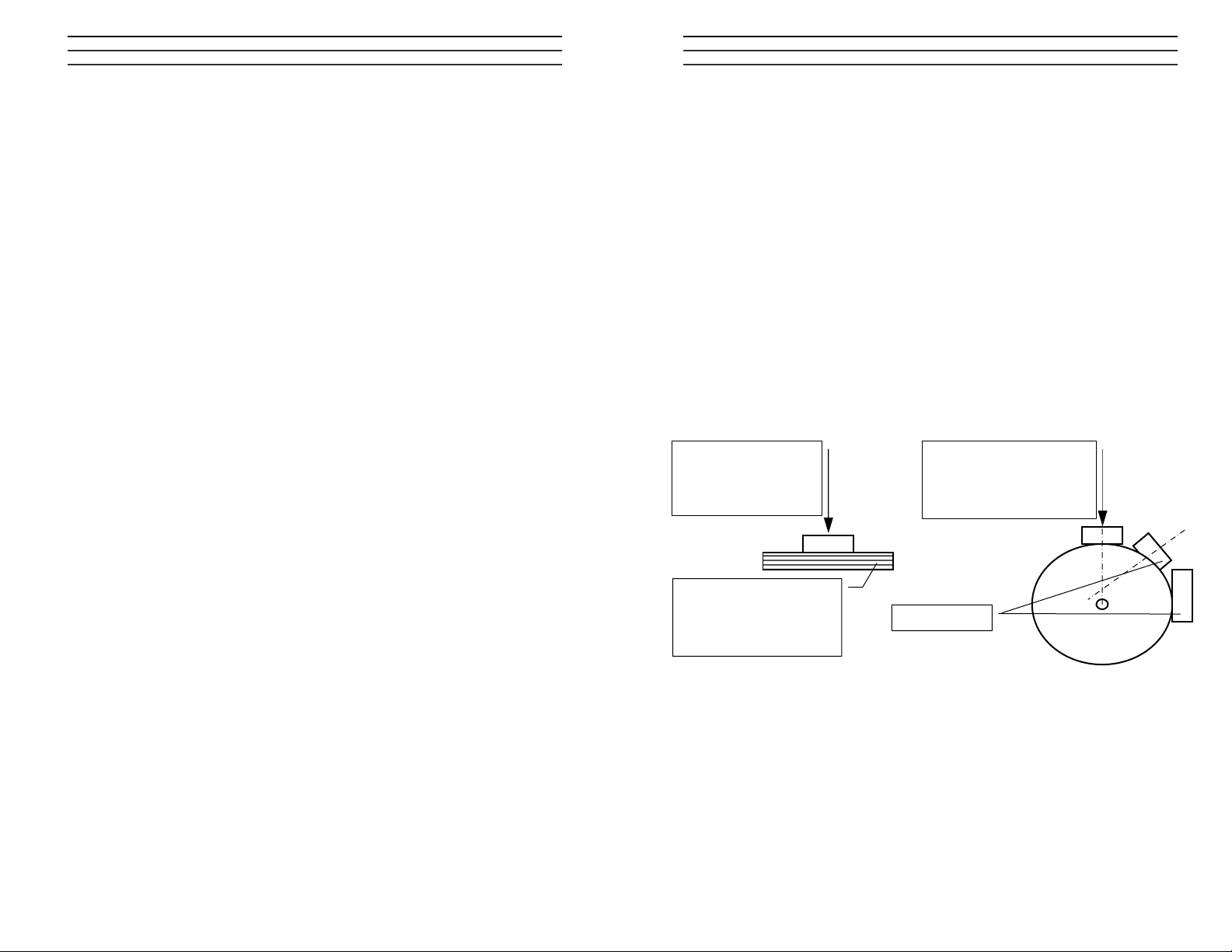
7.0 MEASURING PRINCIPLE
The material in the measuring field is penetrated by an electromagnetic field
whose features change due to the material's quantity of moisture. Because of the
characteristic polarity of the water molecule and the thus resulting high relative
permittivity of water (about 83) the capacity of the measuring field changes
together with the changing moisture of the measuring sample.
Measuring plate at the
back of the instrument
8 x 5 cm
7 x 4,5 cm
Measuring instrument
P2, P4 Measuring plate
8cm long x 5cm broad x 1,3cm depth
LM5 Measuring plate
7cm long x 4,5 cm broad x 0,5cm depth
Caution! When the material thickness is below a certain limit, the measuring
result is falsified.
ELECTROMATIC Equipment Co., Inc.
-10-
ELECTROMATIC Equipment Co., Inc.
-7-
Page 8

8.0 EXCLUSION OF LIABILITY
The producer can not be made liable for any measuring errors and the d amage
that might result from it. This measuring principle is a quick measuring procedure
which can be influenced by product and user-specific margin conditions.
Therefore it is recommended to carry out a pl ausibility check of the measured
values. In every measuring device there is a serial number and a seal of
warranty. If this seal is broken no warranty claims will be accepted. In case of
defect send back your measuring device to Checkline Europe. The device must
be sufficiently packaged for protection reasons. (refer to technical support)
9.0 CARE REGULATIONS
In order to guarantee that your measuring device is kept in good condition,
please take care that it is not imposed to too much mechanical strain (it should
not be dropped or exposed to excessive temperatur es). Always use a dry cloth
when cleaning your measuring device because it can be destroyed by incoming
water or other cleaning agents.
Do not leave your device unattended – put it back into the delivered wooden
case after the measuring procedure.
We recommend an ISO-approved examination of the device in regular intervals
by applying the kiln method or by using the enclosed proof plane PP2 (base plate
of the wooden case)!
If needed, Checkline Europe will also carry out a calibr ation at your expense. In
this case a calibration certificate will be issued and delivered.
ELECTROMATIC Equipment Co., Inc.
-8-
10.0 ISO-APPROVED EXAMINATION OF THE INSTRUMENT
The surface of the proof plane PP2 must not be scratched and must be free of
dust, dirt, fats and moisture.
Field of application: temperatures ranging from 10°C to 30°C, relative humidity
30-80%
Procedure of examination
Torn on the device, place it in the middle of the pr oof plane PP2 and press firmly
onto it. Now check the values on the display against the set measuring v alues in
the table and fill them in the provided table. We have defined the ideal
temperature for your device – 20°C, but it can range between 17°C and 23°C. If
an adjustment is not possible, a calculated correction of the temp erature of the
displayed value is necessary. The corrected value and the set value must be
within the range of tolerance.
Set measuring values for PP2 should be at a temperature of 20°C.
Switch
position
set measuring
value
adjust
tolerance
readjust
tolerance P2 P4
S1 6.4 4.3 0.6 0.9
S2 5.8 4 0.6 0.9
S3 5.1 3.7 0.5 0.8
S4 4.5 3.3 0.5 0.7
S5 3.8 3 0.4 0.6
S6 3.1 2.6 0.4 0.6
Value when held up in the air at switch position 1 is: P2= 1.3% and P4= 2.5%
range of adjustment tolerance by the plant 0.6%
set measuring
switch
position
value
LM5
adjust
tolerance
readjust
tolerance
S1 11,9 0,9 1,5
S2 11 0,8 1,3
S3 10,1 0,8 1,1
S4 9,2 0,7 1,0
S5 8,2 0,6 0,9
S6 7,2 0,5 0,8
Value when held up in the air at switch position 1 is: LM5= 3,7%
range of adjustment tolerance by the plant 0,8%
Example of temperature correction
ELECTROMATIC Equipment Co., Inc.
-9-
Page 9

P2, P4, LM5
PAPER MOISTURE METER
OPERATING INSTRUCTIONS
 Loading...