

Page 1
1
Table of Contents
1.0 Introduction . . . . . . . . . . . . . . . . . . . . . . . . . . . . . . . . . . . . . . . . . . . . . . . . . . . . . . . . 2
2.0 Mounting Procedure . . . . . . . . . . . . . . . . . . . . . . . . . . . . . . . . . . . . . . . . . . . . . . . . . 2
3.0 Operating Procedure . . . . . . . . . . . . . . . . . . . . . . . . . . . . . . . . . . . . . . . . . . . . . . . . 3
3.1 Inserting the material to be measured
3.2 Setting the Maximum Tension Detector (optional)
4.0 Verifying Calibration Accuracy . . . . . . . . . . . . . . . . . . . . . . . . . . . . . . . . . . . . . . . . 4
5.0 Maintenance . . . . . . . . . . . . . . . . . . . . . . . . . . . . . . . . . . . . . . . . . . . . . . . . . . . . . . . . 5
5.1 Calibration Verification Intervals
5.2 Rollers
5.3 Cleaning
6.0 Specifications . . . . . . . . . . . . . . . . . . . . . . . . . . . . . . . . . . . . . . . . . . . . . . . . . . . . . . . 6
7.0 Tension Ranges . . . . . . . . . . . . . . . . . . . . . . . . . . . . . . . . . . . . . . . . . . . . . . . . . . . . . 6
8.0 Dimension Drawings . . . . . . . . . . . . . . . . . . . . . . . . . . . . . . . . . . . . . . . . . . . . . . . . . 7
9.0 Warranty . . . . . . . . . . . . . . . . . . . . . . . . . . . . . . . . . . . . . . . . . . . . . . . . . . . . . . . . . . 8
The device must not be operated in explosion hazard areas and must
not come into contact with aggressive substances.
Tensions that exceed the measuring range of the device by more than
100% may cause a permanent deformation of the measuring spring
and must be avoided under any circumstances.
8
5.0 WARRANTY
ELECTROMATIC Equipment Co., Inc. (ELECTROMATIC) warrants to the
original purchaser that this product is of merchantable quality and confirms
in kind and quality with the descriptions and specifications thereof. Product
failure or malfunction arising out of any defect in workmanship or material in the
product existing at the time of delivery thereof which manifests itself within one
year from the sale of such product, shall be remedied by repair or replacement of
such product, at ELECTROMATIC’s option, except where unauthorized repair,
disassembly, tampering, abuse or misapplication has taken place, as determined by
ELECTROMATIC. All returns for warranty or non-warranty repairs and/or replacement must be authorized by ELECTROMATIC, in advance, with all repacking and
shipping expenses to the address below to be borne by the purchaser.
THE FOREGOING WARRANTY IS IN LIEU OF ALL OTHER
WARRANTIES, EXPRESSED OR IMPLIED, INCLUDING BUT NOT
LIMITED TO, THE WARRANTY OF MERCHANTABILITY AND FITNESS FOR
ANY PARTICULAR PURPOSE OR APPLICATION. ELECTROMATIC SHALL
NOT BE RESPONSIBLE NOR LIABLE FOR ANY CONSEQUENTIAL DAMAGE,
OF ANY KIND OR NATURE, RESULTING FROM THE USE OF SUPPLIED
EQUIPMENT, WHETHER SUCH DAMAGE OCCURS OR IS DISCOVERED
BEFORE, UPON OR AFTER REPLACEMENT OR REPAIR, AND WHETHER OR
NOT SUCH DAMAGE IS CAUSED BY MANUFACTURER’S OR SUPPLIER’S
NEGLIGENCE WITHIN ONE YEAR FROM INVOICE DATE.
Some State jurisdictions or States do not allow the exclusion or limitation of incidental or consequential damages, so the above limitation may not apply to you. The duration of any implied warranty, including, without limitation, fitness for any particular
purpose and merchantability with respect to this product, is limited to the duration of
the foregoing warranty. Some states do not allow limitations on how long an implied
warranty lasts but, not withstanding, this warranty, in the absence of such limitations,
shall extend for one year from the date of invoice.
ELECTROMATIC Equipment Co., Inc.
600 Oakland Ave. Cedarhurst, NY 11516—USA
Tel: 1-800-645-4330/ Tel: 516-295-4300/ Fax: 516-295-4399
Every precaution has been taken in the preparation of this manual. Electromatic Equipment Co., Inc., assumes
no responsibility for errors or omissions. Neither is any liability assumed for damages resulting from the use of
information contained herein. Any brand or product names mentioned herein are used for identification purposes only, and are trademarks or registered trademarks of their respective holders.
WARNING
WARNING
Page 2
2
1.0 INTRODUCTION
The CHECK•LINE®model ODT Tension Meter accurately measures running line
tensions on a wide variety of yarns, fibers, wires, etc. It's designed for fixed mounting
and continuous tension measurement.Threaded mounting holes are provided on the
back side and edge of the housing.
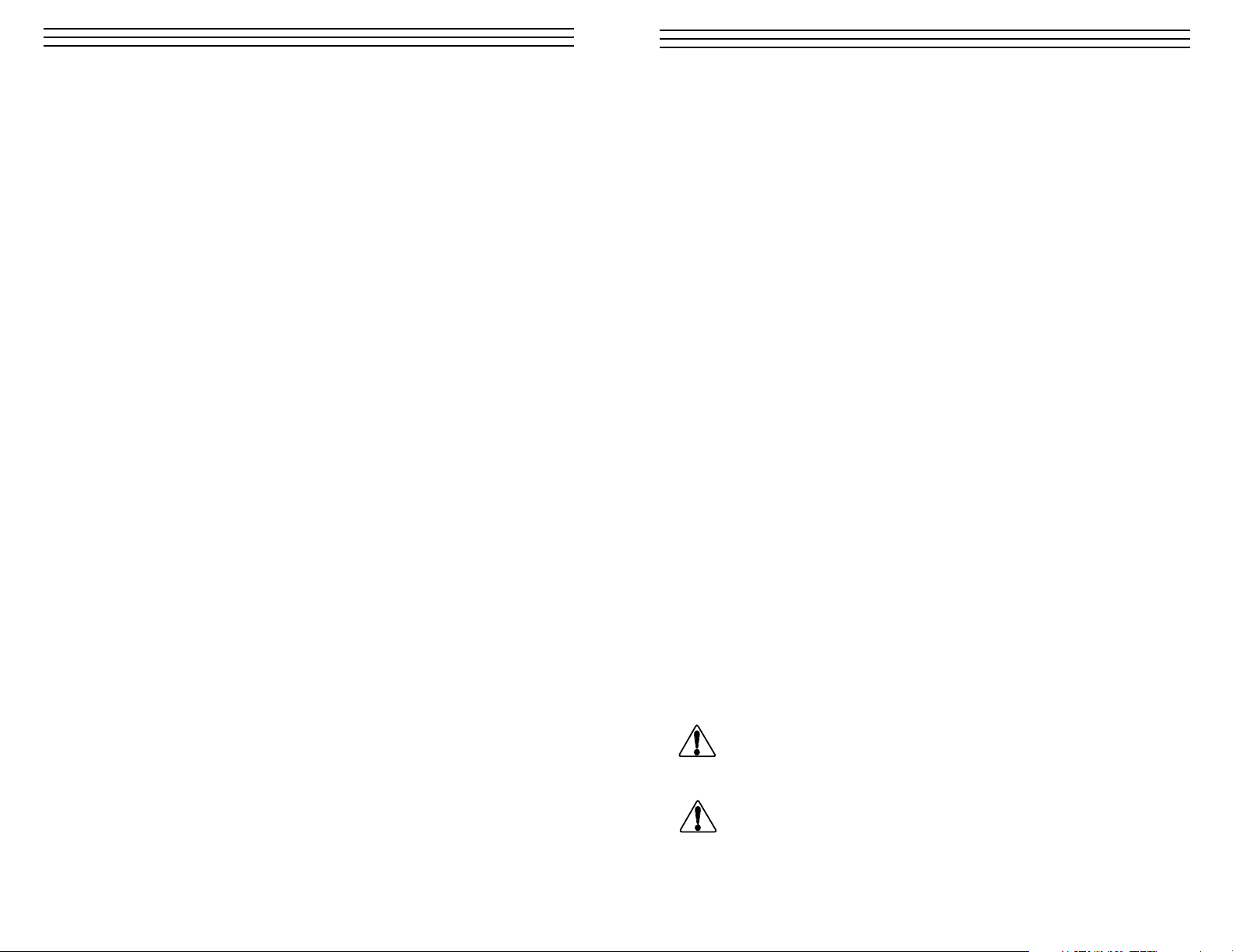
2.0 MOUNTING PROCEDURE
Two mounting holes are provided for fastening the tensionmeter on site, see below.
7
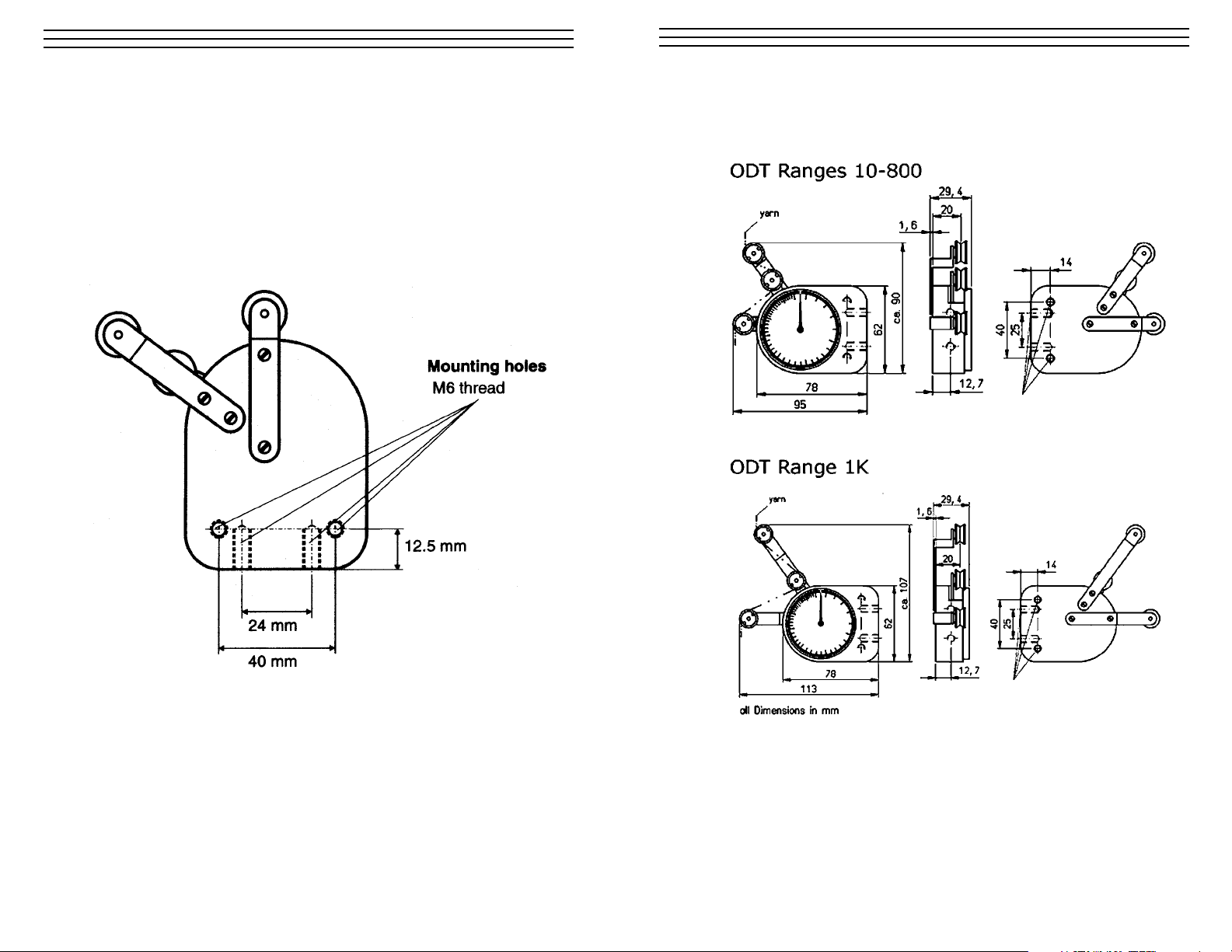
6.0 DIMENSION DRAWINGS
Page 3

3
3.0 OPERATING PROCEDURE
3.1 Inserting the material to be measured
Carefully thread the material to be measured through the measuring roller
and roller guides, as shown below. It is important to ensure that the measured
material runs smoothly through the roller.
To avoid damage do not move the center roller by hand
using force.
3.2 Setting the Maximum Tension Detector (optional)
Need copy?
Are there any other steps that need to be taken
before the gauge begins operating?
6
6.0 SPECIFICATIONS
Calibration According to factory procedure
Accuracy ± 1% full scale (FS) or ± 1 graduation on scale
Scale diameter 2.28 in (58mm)
Temperature range 50 to 113 °F (10 to 45 °C)
Air humidity 85% RH, max.
Housing material Chill-cast aluminum
Housing dimensions 3.1 in x 2.45 in x 1.1 in (78 x 62 x 27 mm) — L x W x H
Weight approx. 0.7 lbs. (300g)
7.0 TENSION RANGES/CALIBRATION MATERIAL
Model Range (grams) Calibration Material*
ODT-10 2-10 Faden: 25 tex
ODT-20 2-20 Faden: 25 tex
ODT-30 3-30 Faden: 25 tex
ODT-50 5-50 PA 0.12mm Ø
ODT-70 10-70 PA 0.12mm Ø
ODT-100 10-100 PA 0.12mm Ø
ODT-200 20-200 PA 0.20mm Ø
ODT-300 20-300 PA 0.20mm Ø
ODT-400 40-400 PA 0.20mm Ø
ODT-500 50-500 PA 0.20mm Ø
ODT-800 20-800 PA 0.20mm Ø
ODT-1K 50-1000 grams PA 0.30mm Ø
* Suitable for 95% of applications. PA = Polyamide Monofilament. If the material
to be measured differs significantly from the factory calibration material in diameter,
rigidity, shape, etc., we recommend calibration using customer material. For this
purpose, a material sample of about 5 m should be supplied. International unit for
tension force: 1 cN = 1.02 g = 0.01 N
WARNING
Page 4

4
4.0 VERIFICATION OF THE ODT CALIBRATION
All tension meters are calibrated according the factory procedure using standard
materials—such as polyamide monofilament (PA)—. The filament sizes are noted in
Section 7 on page 6. Any difference in process material size and rigidity from the
standard material may cause a deviation of the accuracy.
NOTE: In 95% of all industrial applications the factory calibration has proven
to provide the best results and is used for comparative purposes. If the process
material differs significant in size, rigidity and shape we recommend special
calibration using customer`s sample. For this purpose a material sample 5 m long
should be supplied.
Verification Procedure
1. Suspend a known weight that corresponds to the tension to be measured (pay
attention to the correct unit of measure) from the process material, vertically, as
shown below (Always use a fresh portion of the material to be measured).
2. Before the final check, move the process material slowly up and down to
compensate any friction caused by the instrument and thus ensure the repeatability.
3 The tension value should be equal to the value of the suspended weight.
NOTE: If this procedure shows a deviation beyond the allowable tolerance and
a reliable operation is no longer allowed, the instrument has to be recalibrated or
repaired. For recalibration, return the tension meter to the factory.
5
5.0 MAINTENANCE
5.1 Calibration Verification Intervals
Finding the right frequency of calibration accuracy verification depends on several different factors:
• Operating time and load of the tension meter
• Tolerance band defined by the customer
• Changes of the tolerance band compared to previous verifications of
calibration
Therefore, the interval between verifications must be determined by the user`s
Quality Assurance Department based on the user`s experience. Assuming normal
operating time and load as well as careful handling of the tensionmeter, we
recommend a verification interval of 1 year.
5.2 Rollers
You should regularly inspect the rollers to assure that they are running easily and
smoothly. You can replace the rollers yourself, as necessary. When ordering
spare rollers, please indicate the tension meter model and the serial number
(on the rear side of the tension meter).
Example of ordering of spare rollers
Model: ODT-20 (on the rear of the tension meter)
Serial number: 230 - 888888 (on the rear of the tension meter)
Standard rollers: Order number R12013
5.3 Cleaning
When cleaning the unit, do not use any aggressive solvents, such as
trichloroethylene or similar chemicals. No warranty or liability shall
be accepted for damage resulting from improper cleaning.
Page 5

ELECTROMATIC
E Q U I P M E N T C O., I N C.
600 Oakland Ave., Cedarhurst, NY 11516–U.S.A.
TEL: 516-295-4300 • FAX: 516-295-4399
CHECK•LINE
®
INSTRUMENTS
STATIONARY TENSION METER
MODEL ODT
Operating Instructions
CHECK•LINE
®
BY ELECTROMATIC
 Loading...