

Page 1
— WARNING —
1. Test samples can break or shatter, wear eye
and body protection to avoid injury.
2. Do not exceed 500 lbf capacity. Be sure to
set the upper and lower travel limits to avoid
overload.
3. To reset from an overload see page 7.
2 YEAR WARRANTY (restrictions apply)
Imada, Inc. warrants its products to the original purchaser to be free from defects in workmanship and
material under normal use and proper maintenance for two years (one year for adapters, attachments
and cables) from original purchase. This warranty shall not be effective if the product has been subject to
overload, shock load, misuse, negligence, accident or repairs attempted by others than Imada, Inc.
During the warranty period, we will, at our option, either repair or replace defective products. Please
call our customer service department for a return authorization number and return the defective product
to us with freight prepaid.
The foregoing warranty constitutes the SOLE AND EXCLUSIVE WARRANTY, and we hereby disclaim
all other warranties, express, statutory or implied, applicable to the products and/or software, including
but not limited to all implied warranties of merchantability, fitness, non-infringement, results, accuracy,
security and freedom from computer virus. In no event shall Imada, Inc. and/or its affiliated companies be
liable for any incidental, consequential or punitive damages in connection with the use of its products
and/or software.
VERTICAL
MOTORIZED TEST STAND
Model MX-500
11/06
FORCE GAUGE AND DIGITAL DISTANCE METER SOLD SEPARATELY
INSTRUCTION MANUAL
Specifications subject to change without notice.
Page 2
FS
MODE
Manual Operation
Single Cycle
Continuous Cycle
FS Effective
SWITCH SPEED
EMERGENCY
FS Volume
INTRODUCTION
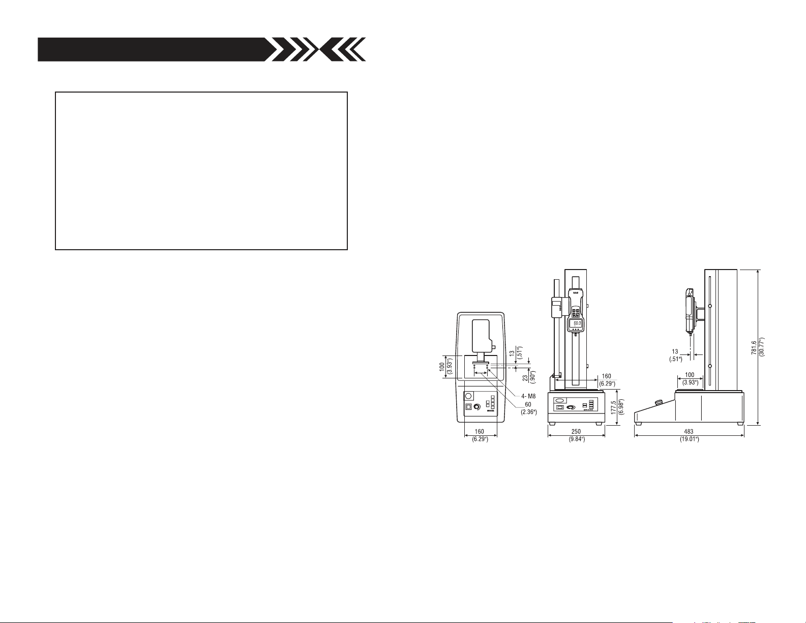
The Model MX-500 Vertical Motorized Test Stand assures
consistent, identical measuring conditions by eliminating
possible human error.
SPECIFICATIONS
Motorized Vertical Test Stand
Model No: MX-500
Max Load: 500 lbf
Speed: 0.2 – 7 in/min
Stroke: 13" (330 mm)
Power: 115/230 VAC
RESET FROM OVERLOAD
If the test stand overloads or locks up during testing, disconnect
the cable connecting the test stand to the force gauge, switch to
Manual Operation and using a direction switch, back off the
crosshead (in the opposite direction from the overload) to
release the load.
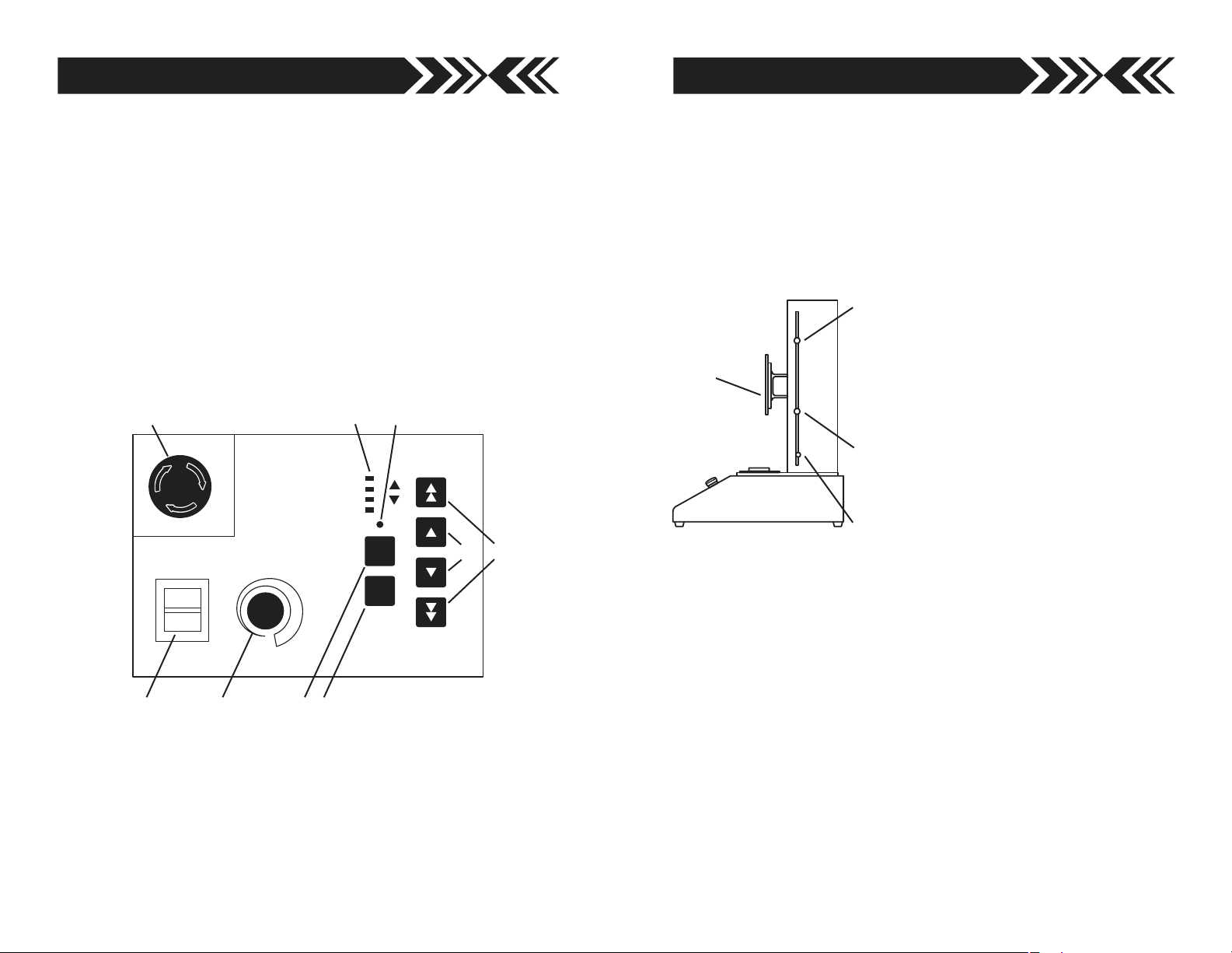
TRAVEL LIMITS
UPPER TRAVEL LIMIT
Cross Head stops moving up when it
reaches this position. To adjust the
CROSS
HEAD
stroke, loosen screw and move the limit
to desired position. Re-tighten screw
securely.
MIDDLE TRAVEL KNOB
Slows the cross head to the speed set by
the Speed Adjust Knob.
LOWER TRAVEL LIMIT
Cross Head stops moving down when it
reaches this position. To adjust the
stroke, loosen screw and move the limit
to desired position. Re-tighten screw
securely.
CAUTION:
Make sure to set the lower travel limit high enough to allow
CONTROL PANEL
Power Switch
Adjustable Speed Direction
Switch
Maximum Speed Direction
Switch
Emergency Stop Switch
Mode Switch
Mode Indicators
Fixed Speed Switch
Fixed Speed Adjustment
adequate clearance for the force gauge and attachments, so it
will not be overloaded.
To prevent accidental movement of the lower limit position,
replace the thumbscrew with an M5 Allen screw so that an Allen
wrench will be required to adjust it.
Speed Adjust Knob
2 7
Page 3

3. Press Mode Switch and select Continuous Cycle. Press
Mode switch again and the Continuous Cycle light
begins blinking.
GENERAL OPERATION
Make sure of the following before plugging the power cord into
the 115VAC output.
4. Select test speed:
A. Turn the Speed Adjust Knob or
B. Press Fixed Speed Switch , the Mode Indicator lights.
(overrides Speed Adjust Knob). Fixed Speed can be
adjusted by using a small screwdriver to adjust the FS
Volume potentiometer.
5. Press ZERO switch on Z2 or ZP gauge and start testing.
Single Preset One Way Force Control
Press the Maximum Speed Direction Switch . The cross
head moves (up or down) at maximum speed until the force
value reaches the Low setpoint. The speed then changes to
either the speed set by the Speed Adjust Knob or the
Fixed Speed Switch if FS has been pressed. When the force
value reaches the High setpoint programmed on the Z2 or ZP
force gauge, the test stops.
High/Low Setpoints Force Control
Press the Adjustable Speed Direction Switch . The cross
head moves (up or down) at either the speed set by the Speed
Adjust Knob or the Fixed Speed Switch if FS has been
pressed. When the force value reaches the Low setpoint, force
control is activated to maintain the force between the High
and Low setpoints programmed on the Z2 or ZP force gauge.
To end force control, press a or direction switch or the
Emergency Switch .
EMERGENCY BRAKE STOP SWITCH
Push the Emergency Stop Switch whenever you are in an
emergency situation. To re-engage the Emergency Stop Switch,
simply turn the switch clockwise.
1. Turn Speed Adjustment Knob to a middle position.
2. Turn the Emergency Switch clockwise to make sure the
Emergency Brake is re-engaged.
3. Move the upper and lower travel limits so that there is
separation between them (see Page 7 of this manual).
4. Connect power cord to stand and plug into 115/230 VAC outlet.
5. Turn on Power Switch . The Orange power lamp will light.
MANUAL OPERATION
When the Power is turned on, startup mode is Manual Operation
the appropriate Mode Indicator will light. Manual Mode is for
initial test position setup.
1. Press either Adjustable Speed Direction Switch to jog the
cross head in that direction or press and hold, and the cross
head moves until you release the switch. (The cross head speed
is set by either the Speed Adjust Knob or the Fixed Speed
Switch ).
Press either Maximum Speed Direction Switch to jog the
cross head in that direction or press and hold, and the cross
head moves at maximum speed until you release the switch.
2. Select speed
A. Turn the Speed Adjust Knob or
B. Press Fixed Speed Switch , to override the Speed
Adjust Knob (the Mode Indicator lights). Fixed Speed
can be adjusted by using a small screwdriver to adjust the
FS Volume potentiometer.
3. Regardless of the preset speed, when either Maximum Speed
Direction Switch is pressed, the cross head moves at
maximum speed.
6 3
Page 4

SINGLE-CYCLE OPERATION
When the Power is turned on, startup mode is Manual Operation.
1. Press Mode Switch and select Single Cycle, the Mode
Indicator lights.
2. Test Operation
Adjustable Speed Testing
Press either Adjustable Speed Direction Switch and the
cross head moves (up or down) at the speed set by the Speed
Adjust Knob . When the cross head reaches the lower or upper
travel limit it stops, then returns to the opposite travel limit.
Fixed Speed Testing
Press the Fixed Speed Switch , the Mode Indicator will
light. Press either Adjustable Speed Direction Switch and
the cross head moves (up or down) at the speed set by the
Fixed Speed Switch . When the cross head reaches the
lower or upper travel limit it stops, then returns to the
opposite travel limit.
Maximum Speed Testing
Press either Maximum Speed Direction Switch and the
cross head moves (up or down) at maximum speed. When the
cross head reaches lower or upper travel limit it stops and
then returns to the opposite travel limit.
CONTINUOUS CYCLE OPERATION
When the Power is turned on, startup mode is Manual Operation.
1. Press Mode Switch and select Continuous Cycle, the Mode
Indicator lights.
2. Test Operation
Adjustable Speed Testing
Press either Adjustable Speed Direction Switch and the
cross head moves (up or down) at the speed set by the Speed
Adjust Knob . When the cross head reaches the lower or
upper travel limit it stops, then returns to the opposite travel
limit. The cross head automatically repeats this cycle until a
or direction switch or the Emergency Switch is pressed.
Fixed Speed Testing
Press the Fixed Speed Switch , the Mode Indicator will
light. Press either Adjustable Speed Direction Switch and
the cross head moves (up or down) at the speed set by the
Fixed Speed Switch . When the cross head reaches the lower
or upper travel limit it stops, then returns to the opposite travel
limit. The cross head automatically repeats this cycle until a
or direction switch or the Emergency Switch is pressed.
Maximum Speed Testing
Press the Maximum Speed Direction Switch (up or down).
The cross head moves (up or down) at maximum speed until it
reaches the lower or upper travel limit and then stops and
returns to the opposite travel limit. The cross head automatically
repeats this cycle until a or direction switch or the
Emergency Switch is pressed.
FORCE CONTROL OPERATION
MX-500 test stand becomes a force control system when connected
to an IMADA Z2 or ZP digital force gauge with a CB-501 interface
cable. This feature may be used as overload protection and can
help prevent overload damage in most cases, but due to the wide
variety of testing conditions a guarantee is not possible.
1. Connect MX-500 test stand and IMADA Z2 or ZP force gauge
with a CB-501 interface cable.
2. Program High and Low setpoints on IMADA Z2 or ZP force
gauge. (Refer to Z2 or ZP Manual, Programming Setpoints
section)
4 5
 Loading...