

Page 1
Specifications subject to change without notice.
2 YEAR WARRANTY (restrictions apply)
Imada, Inc. warrants its products to the original purchaser to be free from defects in workmanship and
material under normal use and proper maintenance for two years (one year for adapters, attachments,
and cables) from original purchase. This warranty only covers defective material and labor and does not
cover calibration, batteries, freight, fees and expenses and shall not be effective if the product has been
subject to overload, shock load, misuse, negligence, accident or repairs attempted by others than Imada, Inc.
During the warranty period, we will, at our option, either repair or replace defective products. Please
call our customer service department for a return authorization number and return the defective product
to us with freight prepaid.
The foregoing warranty constitutes the SOLE AND EXCLUSIVE WARRANTY, and we hereby disclaim
all other warranties, express, statutory or implied, applicable to the products and/or software, including
but not limited to all implied warranties of merchantability, fitness, non-infringement, results, accuracy,
security and freedom from computer virus. In no event shall Imada, Inc. and/or its affiliated companies be
liable for any incidental, consequential or punitive damages in connection with the use of its products
and/or software.
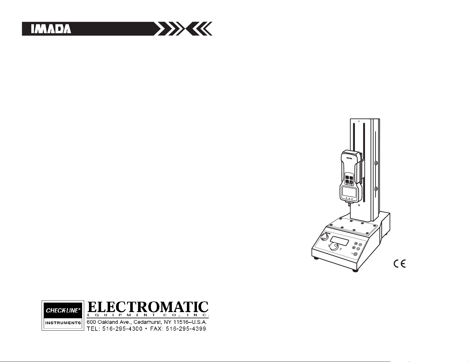
VERTICAL MOTORIZED
TEST STAND
INSTRUCTION MANUAL
FORCE GAUGE AND DIGITAL DISTANCE METER SOLD SEPARATELY
Models: MX2-110 & MX2-275
DIG
IT
AL FORCE GA
U
GE
00.0
NG
Lb
OK +NG
OVERLO
AD
ZERO
SEND PEAK
ON
OFF
Page 2
15
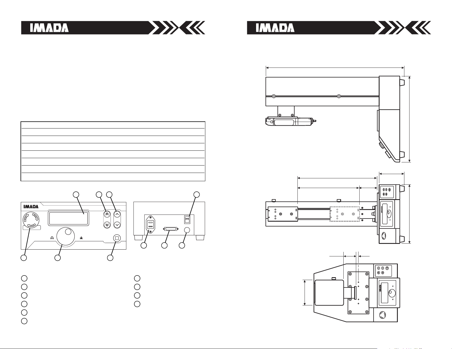
DIMENSIONS
MX2-275
Back
280
(11.02")
120
(4.72")
421
(16.57")
660 (25.48")
380 (14.96")
296
(11.65")
84
(3.30")
120
(4.72")
12
(.47")
59.3
(2.33")
Select
Enter
Select
Enter
Back
2
CONTROL PANEL
LCD screen
Program Dial
Single Speed Button
Double Speed Button
Back Button (Mode)
Emergency Stop/Reset
1
2
3
4
5
6
BACK OF STAND
Power Switch
Force Control port
Fuse
AC Power
7
8
9
10
Select
Enter
Back
MANUAL MODE
4.40 in/min
# JOG MOVE
INTRODUCTION
The MX2 Vertical Motorized Test Stand uses a maintenance-free,
brushless, DC motor to provide smooth and powerful operation and
ensure consistent test results. Automated fatigue tests are easy to
setup using the unique program dial and menu screens to control
speed, timer and cycle count. Force controlled non-destructive tests
are also easy to setup and program. Manual mode features unique
movement control in precise increments, for precision testing.
BACK OF STANDCONTROL PANEL
1 7
2
10
5
4
8 9
6
3
SPECIFICATIONS
Model MX2-110 MX2-275
Max Load 110 lbf 275 lbf
Standard Speed .4~12 in/min (10~305 mm/min) .4~12 in/min (10~305 mm/min)
Optional Fast Speed .8~23.5 in/min (20~600 mm/min) .9~23.5 in/min (20~600 mm/min)
Optional Slow Speed .1~3.5 in/min (3~90 mm/min) .1~2.9 in/min (2~75 mm/min)
Stroke 9.44" (240mm) 11.6" (295mm)
Deflection .5 mm at maximum load .5 mm at maximum load
Power 115/230 VAC 115/230 VAC
Page 3
314
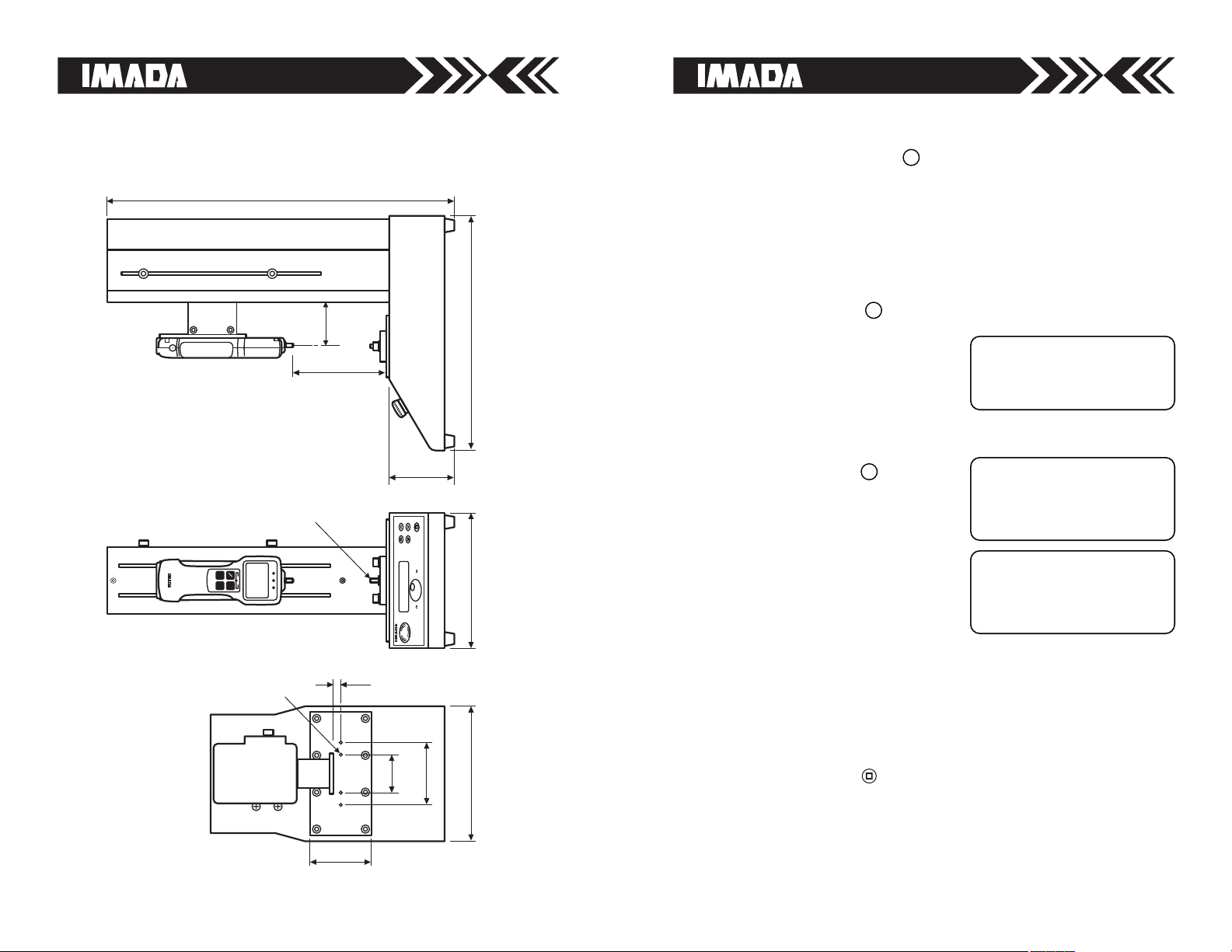
DIMENSIONS
MX2-110
71
(2.79")
220
(8.66")
200
(7.87")
380
(14.9")
562
(22.1")
110
(4.33")
0~240
(0~9.44")
M6
12
(.47")
100
(7.87")
60
(2.36")
M8
100
(3.93")
DIGITAL FORCE GAUGE
00.0
NG
Lb
OK +NG
OVERLOAD
ZERO
SEND PEAK
ON
OFF
Select
Enter
Back
Changing Speed Units
1. Press the Back button to
change to Cycle Mode.
2. Press and hold the dial until the
Config Mode screen appears.
3. Turn the dial until Extra Config
appears (arrows
<>indicate
current selection).
4. Press the dial to enter Extra
Config Mode.
5. Turn the dial in Extra Config
Mode until Unit Select appears.
6. Press the dial to enter.
7. Turn the dial to select inch or
millimeter.
8. Press the Back button twice to
exit Extra Config Mode and return
to Cycle Mode. Unit selection is
then retained in memory for
future tests.
5
Check the following before testing
1. Turn the Emergency Stop clockwise to make sure it is
released. Press it whenever you are in an emergency situation.
2. Move the Upper and Lower Travel Limits so that there is
separation between them or the cross head will not move and
and a limit error is displayed on the LCD screen (see page 5).
3. Connect the power cord to the proper AC power.
4. Turn on power switch on the back of the test stand.
When the power is turned on Manual
Mode/Speed Adjust is the startup
screen. The default speed unit is
mm/min.
6
7
MANUAL MODE
5.50 mm/min
# SPEED ADJUST
CONFIG MODE
< EXTRA CONFIG >
ENTER EXTRA CONFIG
EXTRA CONFIG MODE
UNIT SELECT
< INCH
Page 4

13
– WARNING –
1. Test samples can break or shatter, wear eye
and body protection to avoid injury.
2. Do not exceed the capacity of the test
stand. Be sure to set the upper and lower
travel limits to avoid overload.
OPTIONAL DISTANCE METER
Available for mounting to test stand.
Distance Meter Specifications
Display Push button for inch/mm, zero set and on/off
Resolution 0.0005"/0.01mm
Accuracy 0.1% of reading or 0.005"/0.1mm, whichever is greater
4
MANUAL MODE
Manual Mode/Jog Move is used mainly to position the cross head
prior to testing and for precise increment testing.
When power is turned on, Manual Mode/Speed Adjust is the startup
screen. There are two menu items in the Manual Mode, Speed Adjust
and Jog Move. Press the program dial to toggle the menu items.
Manual Mode Operation
Press and hold , and the cross head moves up at the speed set in
Speed Adjust, stopping when it reaches the upper travel limit. Press
and hold and the cross head moves down, stopping when it
reaches the lower travel limit. The cross head stops when either
button is released.
Press and hold and the cross head moves up at maximum speed
(displayed on the screen) stopping when it reaches the upper travel
limit. Press and hold and the cross head moves down, stopping
when it reaches the lower travel limit. The cross head stops when
either button is released.
Jog Move Operation
Use Jog Move to test or position by turning the dial to move the
gauge and attachment in precise increments.
Speed Adjust
Speed Adjust is displayed at the
bottom of the screen. Turn the
program dial to set the speed.
Jog Move
Jog Move is displayed at the bottom of
the screen. Turn the dial to make
precise adjustments to the cross head
for positioning and testing.
Each click of the dial moves the cross head (standard speed, under no
load) approximately .015mm for MX2-110 and .01mm for MX2-275.
All the up and down speed buttons work in Jog Move.
MANUAL MODE
5.50 in/min
# SPEED ADJUST
MANUAL MODE
5.50 in/min
# JOG MOVE
Page 5

512
RESET FROM OVERLOAD
If the test stand overloads or locks up during testing, turn off both
test stand and force gauge. Then turn on the test stand and using
the direction switch, back off the cross head (in the opposite
direction from the overload) to release the load.
EMERGENCY BRAKE STOP SWITCH
Push the Emergency Stop whenever you are in an emergency
situation. Turn the switch clockwise to release.
6
====================
EMERGENCY
STOP
====================
====================
RELEASE ALARM
RESTART SYSTEM
====================
CYCLE MODE
====================
LIMIT
====================
CYCLE MODE
====================
COUNTER FULL
====================
Error Screens
Emergency Stop– These first two
screens will display alternately. Turn
the Reset switch clockwise
Comparator Error– Make sure
Comparator menu item in Extra
Config is set to OFF, unless force
control is setup, then comparator
must be ON.
Limit– The travel limit has been
reached. Adjust the travel limit to
allow more space or move in the
opposite direction
Counter Full– Select Cycle Mode
and press the program dial to clear
the counter.
CYCLE MODE
=====================
COMPARATOR ERROR
=====================
TROUBLESHOOTING SETTING TRAVEL LIMITS
For a compression test
loosen the upper travel limit
thumbscrew and move it to
the top. Press and hold to
move the force gauge and
attachment up until there is
adequate clearance for testing.
Then move the upper travel
limit down to this position
and tighten securely. Loosen
and move the lower travel limit to the bottom. *Press and hold to
move the gauge and attachment and stop when they reach the test
material.The distance travelled during compression must be added to
determine the position of the lower travel limit. Be careful, the force
gauge can be overloaded whether on or off. Press and hold or use
Jog Move to move the gauge and attachment to the desired position.
Move the lower travel limt to this position and tighten securely.
For a tension test loosen the lower travel limit thumbscrew and
move it to the bottom. *Press and hold and move the force gauge
and attachment down and stop when they reach the test material.
Press and hold or use Jog Move to engage the test material. Be
careful, the force gauge can be overloaded whether on or off.
Move the lower travel limit to this position and tighten securely. Press
and hold to move the force gauge and attachment up to allow
adequate clearance for testing. Move the upper travel limit to this
position and tighten securely.
*CAUTION: Set the lower travel limit to allow adequate clearance for
the gauge and attachments, so they do not crash into the test material.
To prevent accidental movement of the lower limit position, replace
the thumbscrew with an M4 Allen screw so an Allen wrench will be
required to adjust it.
FORCE GAUGE
UPPER TRAVEL LIMIT
THUMBSCREW
LOWER TRAVEL LIMIT
THUMBSCREW
CROSS HEAD
ATTACHMENT
Page 6

116
Force Control Operation
Maintain Force Between High/Low Setpoints
Press either single arrow button or and the cross head moves
at Start Speed, stops at the low setpoint on the Z Series force gauge
and Keeps (holds) applied force between the force gauge’s high/low
setpoints for the programmed Timer Limit using Measuring Speed
and then moves to starting travel limit at Return Speed. The cycle is
repeated until the Counter Limit is reached.
Increase Force to High Setpoint and Stop
Using the same programming setup, press either double arrow or
and the cross head moves at Start Speed and slows to Measuring
Speed at the low setpoint on the Z Series force gauge. When the
applied force reaches the gauge’s high setpoint movement stops
and the position is held for the programmed Timer Limit. The cross
head then moves back to the starting travel limit at Return Speed.
This cycle is repeated until the Counter Limit is reached.
Conditional Overload Prevention
When a Z Series force gauge is mounted and connected to an MX2
stand with a CB-704 or CB-707 cable, Conditional Overload Prevention
engages at 110% of gauge capacity and stops test stand movement.
Depending upon test speed and other variables, movement may be
stopped quickly enough to prevent damage to the gauge in most
cases, but due to the wide variety of testing conditions a guarantee
is not possible.
STATUS INDICATOR
READY: READY TO TEST
START: TEST AT START SPEED
SLOW: TEST AT MEASURING SPEED IN FORCE CONTROL
KEEP: HOLD DURATION TIME
BACK: RETURN TO START
CYCLE MODE
Cycle Mode is used for automated single or multiple cycle tests such
as fatigue testing.
Turn on the stand and press Back button to enter Cycle mode.
The Cycle Mode main screen displays as below.
CYCLE MODE
READY 0.00 in/min
0 / 1
00'00.0 / 00'00.0
ACTUAL CYCLE COUNT
ACTUAL ELAPSED KEEP (HOLD DURATION TIME)
RESETS AUTOMATICALLY TO ZERO AT START
COUNTER LIMIT
(PROGRAMMED
NUMBER OF CYCLES
65,535 MAX.)
TIMER LIMIT
(PROGRAMMED HOLD DURATION TIME
99' 59.9 SEC MAX.)
ACTUAL SPEED
Programming Cycle Mode
Config Mode Menu
1. In Cycle Mode, press and hold the program dial until Config
Mode appears.
2. Turn the dial to view menu items and press the dial to select a
menu item (the arrows
<>indicate the current selection).
3. Turn the dial to make adjustments or select options for that item.
4. Press the dial again to confirm and return to menu items.
5. Press the Back button to exit Config Mode and return to Cycle
Mode. Selections are then saved in memory.
To reset the actual cycle count press
the dial and turn it to select Yes or
No and press the dial to confirm
(not possible if count is zero).
CYCLE MODE
CLEAR COUNTER?
YES >NO
00'00.0 / 00'00.0
Page 7

710
CONFIG MODE
< START SPEED
7.00 in/min
CONFIG MODE
< COUNTER LIMIT >
{}
CONFIG MODE
< TIMER LIMIT >
00'00.8
CONFIG MODE
< MEASURING SPEED >
1.90 in/min
CONFIG MODE
< RETURN SPEED >
11.50 in/min
Start Speed– the cross head
advances toward the travel limit at
this speed
Measuring Speed– skip this item in
Cycle Mode
Extra Config– skip this item in
Cycle Mode
Return Speed– the cross head
returns to the starting travel limit at
this speed
Timer Limit– Keep (hold time
duration) 99' 59.9 seconds max.,
default is 1 second
Counter Limit– counts up to 65,535
cycles max., default is 1 cycle,
{} = continuous cycle, doesn’t stop
Press the Back button to exit Config
Mode and return to Cycle Mode.
Selections are then saved in memory.
CONFIG MODE
< EXTRA CONFIG >
ENTER EXTRA CONFIG
Cycle Mode Operation
Press a direction button , , or and the cross head moves
at Start Speed, stops for the programmed Timer Limit at the travel
limit, then returns to the opposite travel limit at the programmed
Return Speed. The cycle is repeated until the Counter Limit is
reached.
EXTRA CONFIG MODE
<CLEAR ALL CONFIG >
YES >NO
EXTRA CONFIG MODE
< SEND SIGNAL >
OFF
TIP: Programming Z Series Force Gauge High/Low Setpoints
For further instructions refer to the Z Series manual.
1. Turn on the gauge. Press PEAK and ZERO for 3 seconds to enter
Power-On programming (CF9 flashes with solid F0).
2. Press PEAK or ZERO to view the selections. Select CF9 F1 and
press SEND.
3. –HI– displays, then the high set value (i.e. H
10.0). Press PEAK to increase and ZERO to
decrease, press SEND to select. –LO–
displays then the low set value (i.e. L 5.0).
Press PEAK to increase and ZERO to
decrease, press SEND to select, CF9 End
displays. Press SEND again to exit.
EXTRA CONFIG MODE
UNIT SELECT
< INCH
Output Test– Factory use only
Send Signal– Sends one data to
gauge memory at Keep (hold) point
requires CB-704 cable. Saving data to
computer and gauge memory requires
CB-707 cable.
Unit Select– inch or millimeter
Clear All Config– Yes/No Returns to
factory setup
Press the Back button twice to
return to Cycle mode. Selections are
then saved in memory.
EXTRA CONFIG MODE
< OUTPUT TEST >
Page 8

9
EXTRA CONFIG MODE
< ZERO ON START >
OFF
EXTRA CONFIG MODE
< INPUT MONITOR >
EXTRA CONFIG MODE
< RECORD TRIGGER >
OFF
EXTRA CONFIG MODE
<BUZZER ON COUNT UP>
ON
EXTRA CONFIG MODE
< COMPARATOR >
ON
Buzzer On Count Up– ON or OFF
beeps when programmed number of
cycles is completed.
Comparator– ON or OFF
On for force control; test stand and
force gauge must be connected with
CB-704 or CB-707 cable or screen
will display “Comparator Error” on
startup
Record Trigger– OFF (Factory use
only)
Zero On Start– ON or OFF
Tares the gauge before starting
Input Monitor– Factory use only
Programming Force Control Mode (cont’d)
Extra Config Mode Menu
5. Turn the dial until Extra Config
appears on the screen.
6. Press the dial to enter Extra Config
Mode.
7. Turn the dial to view menu items and press the dial to select a
menu item (the arrows
<>
indicate the current selection).
8. Turn the dial to make adjustments to that item or select options.
9. Press the dial again to confirm and return to menu items.
10. Press the Back button twice to exit Extra Config Mode and
return to Cycle Mode. Unit selection is then retained in memory
for future tests.
CONFIG MODE
< EXTRA CONFIG >
ENTER EXTRA CONFIG
Start Speed– the cross head advances
toward the travel limit at this speed
Measuring Speed– engages in force
control mode when applied force
reaches the low setpoint on the Z
Series force gauge. Measuring speed
cannot exceed Start Speed
Return Speed– the cross head
returns to the starting travel limit at
this speed
Timer Limit– Keep (hold time
duration) 99' 59.9 seconds max.,
default is 1 second
Counter Limit– counts up to 65,535
cycles max., default is 1 cycle,
{} = continuous cycle, doesn’t stop
CONFIG MODE
< START SPEED
7.00 in/min
CONFIG MODE
< MEASURING SPEED >
1.90 in/min
Programming Force Control Mode
Config Mode Menu
1. Turn on the stand and press Back button to enter Cycle Mode.
2. Press and hold the program dial until Config Mode appears.
3. Turn the dial to view menu items and press the dial to select a
menu item (the arrows
<>
indicate the current selection).
4. Turn the dial to make adjustments to that item or select options.
5. Press the dial again to confirm and return to menu items.
CONFIG MODE
< TIMER LIMIT >
00'00.8
CONFIG MODE
< RETURN SPEED >
11.50 in/min
CONFIG MODE
< COUNTER LIMIT >
{}
FORCE CONTROL MODE
Force Control Mode is used for automated single or multiple cycle
non-destructive tests. The stand must be connected to a Imada Z Series
force gauge with a CB-704 or CB-707 cable. The following menu items
must be set; speeds, timer limit, counter limit and comparator set to
On. Z Series force gauge high/low setpoints must be also programmed.
8
 Loading...