

Page 1

Notes
Table of Contents
1.0 Introduction ..........................................................................................................
1.1 Models
1.2 Unpacking
2.0 Overview ...............................................................................................................
2.1 Controls
2.2 Complete kit
2.3 Optional accessories
3.0 Set-Up Procedures ................................................................................................
3.1 Battery Insertion and Replacement
3.2 Power On and Off
3.3 Reversing the display
3.4 Zero adjustment of the measuring positon
4.0 Taking A Measurement ........................................................................................
4.1 Inserting the process material
4.2 Measuring the process material
4.3 Removing the process material
5.0 Damping Mode .....................................................................................................
5.1 Switching Damping on and off
5.2 Modifying the Damping Factor
5.3 Setting a new Damping Factor
6.0 Memory Modes ....................................................................................................
6.1 Memory Mode selection
03
04
05
07
08
09
– 28 –
7.0 Data Logging ......................................................................................................... 11
7.1 Data logging in Mode “S” (Standard)
7.2 Data logging in Mode “C” (Continuous)
7.3 Data logging in Mode “L” (Limit)
7.4 Data logging in Mode “F” (Fast)
8.0 Recalling the stored tension values ..................................................................... 15
8.1 Recalling stored tension values in Mode “S” (Standard)
8.2 Recalling stored tension values in Mode “C” (Continuous)
8.3 Recalling stored tension values in Mode “L” (Limit)
8.4 Recalling stored tension values in Mode “F” (Fast)
– 1 –
Page 2

9.0 Memory Management .......................................................................................... 22
9.1 Clearing the KXE memory
9.2 Memory function HOLD
10.0 Error Messages ..................................................................................................... 23
11.0 PC Communications (RS-232 Interface) ........................................................... 24
11.1 TENSION INSPECT program
11.2 Windows Terminal Program
12.0 Specifications ......................................................................................................... 25
13.0 Pin Assignments .................................................................................................... 26
13.1 Interface Signals
13.2 Analog Cable
14.0 Warranty ............................................................................................................... 27
14.0 Warranty
The manufacturer warrants to the original purchaser that this product is of merchantable
quality and confirms in kind and quality with the descriptions and specifications thereof.
Product failure or malfunction arising out of any defect in workmanship or material in
the product existing at the time of delivery thereof which manifests itself within one
year from the sale of such product, shall be remedied by repair or replacement of such
product, at the manufacturer’s option, except where unauthorized repair, disassembly,
tampering, abuse or misapplication has taken place, as determined by the manufacturer.
All returns for warranty or non-warranty repairs and/or replacement must be authorized
by the manufacturer, in advance, with all repacking and shipping expenses to the
address below to be borne by the purchaser.
THE FOREGOING WARRANTY IS IN LIEU OF ALL OTHER WARRANTIES,
EXPRESSED OR IMPLIED, INCLUDING BUT NOT LIMITED TO, THE
WARRANTY OF MERCHANTABILITY AND FITNESS FOR ANY PARTICULAR
PURPOSE OR APPLICATION. ELECTROMATIC SHALL NOT BE RESPONSIBLE
NOR LIABLE FOR ANY CONSEQUENTIAL DAMAGE, OF ANY KIND OR
NATURE, RESULTING FROM THE USE OF SUPPLIED EQUIPMENT, WHETHER
SUCH DAMAGE OCCURS OR IS DISCOVERED BEFORE, UPON OR AFTER
REPLACEMENT OR REPAIR, AND WHETHER OR NOT SUCH DAMAGE IS
CAUSED BY MANUFACTURER’S OR SUPPLIER’S NEGLIGENCE WITHIN ONE
YEAR FROM INVOICE DATE.
Some State jurisdictions or States do not allow the exclusion or limitation of incidental
or consequential damages, so the above limitation may not apply to you. The duration
of any implied warranty, including, without limitation, fitness for any particular
purpose and merchantability with respect to this product, islimited to the duration of
the foregoing warranty. Some states do not allow limitations on how long an implied
warranty lasts but, not withstanding, this warranty, in the absence of such limitations,
shall extend for one year from the date of invoice.
Important Operating Notes
To avoid damage, do not move the center roller by hand.
Tensions that exceed the tension range of the instrument by more
than 100% may cause permanent damage to the measuring spring
and must be avoided under any circumstances.
The device must not be operated in potentially explosive areas and
must not come into contact with aggressive substances
– 2 –
Every precaution has been taken in the preparation of this manual. The manufacturer, assumes no responsibility for errors
or omissions. Neither is any liability assumed for damages resulting from the use of information contained herein. Any
brand or product names mentioned herein are used for identification purposes only, and are trademarks or registered
trademarks of their respective holders.
– 27 –
Page 3
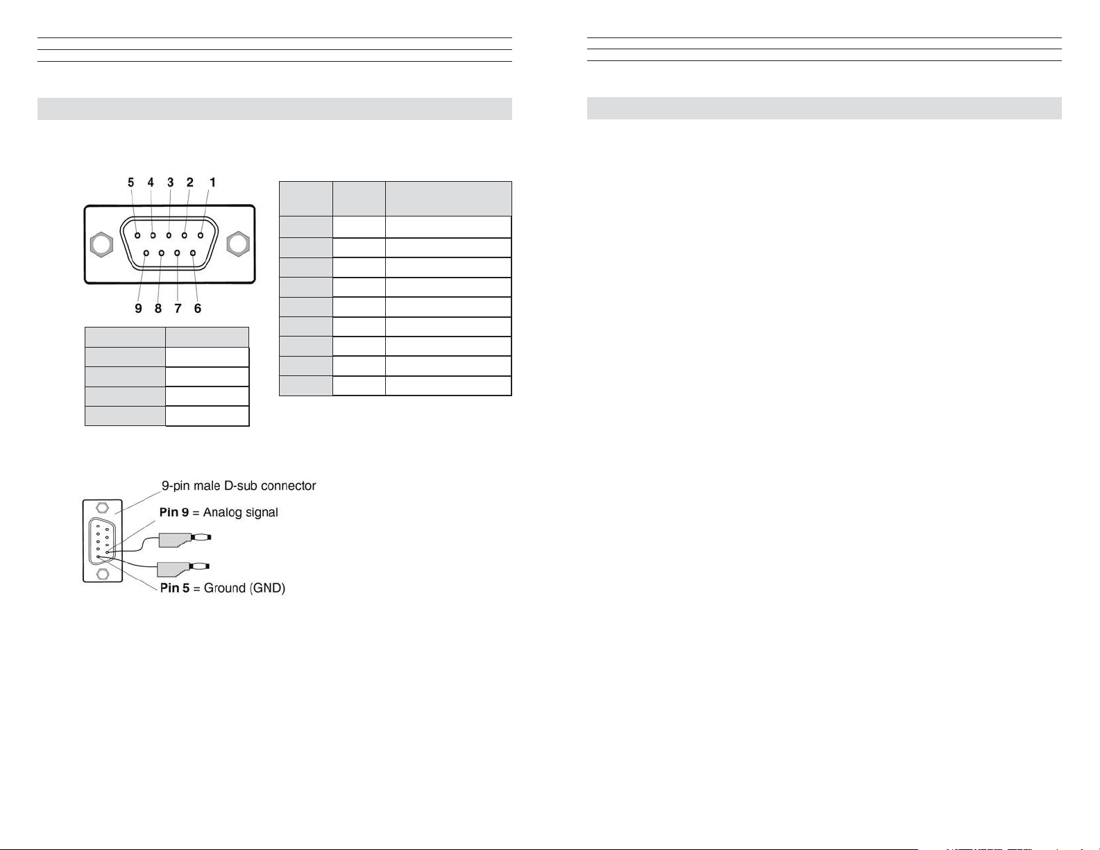
13.0 Pin Assignments
13.1 Pin Assignment and Signals of the Interface (9-Pin D-Sub Connector)
Pin
Number
Signal RS-232-C
Data Bit Bit
Stop Bit 1 Bit
Parity None
Baud Rate 19200
13.2 Pin Assignment of the Analog Cable (Option ETX-CA)
Signal Description
1 Not Assigned
2 TXD 1 Bit
3 RXD None
4 Not Assigned
5 GND Ground
6 Not Assigned
7 RTS READY TO SEND
8 Not Assigned
9 2 V DC Analog Signal
1.0 Introduction
The KXE Warp Tension Meter is designed to measure tensions during warping and
weaving. The unique sensor configuration provided two 25 mm wide cylindrical roller
for the capture of two groups of yarns, one on each side of the sensor for measurement.
Therefore the sensor will be measuring 50 mm of ends while the process is running.
The electronic indicator provides for measurement and storage of the critical high and
low peaks that will be measuring in the weaving operation. These peaks can them be
analyzed and used for process evaluation. Stored data can be transferred to a PC and
analyzed using the FREE Tension Inspect software.
1.1 Models
KXE-20 0.5 – 20.0 daN measuring range.
KXE-50 0.5 – 50.0 daN measuring range.
1.2 Unpacking
Unpack the tension meter and inspect it for any shipping damage. Notices of defect
mustbe filed immediately, in writing, at the latest within 10 days on receipt of the goods.
– 26 –
– 3 –
Page 4
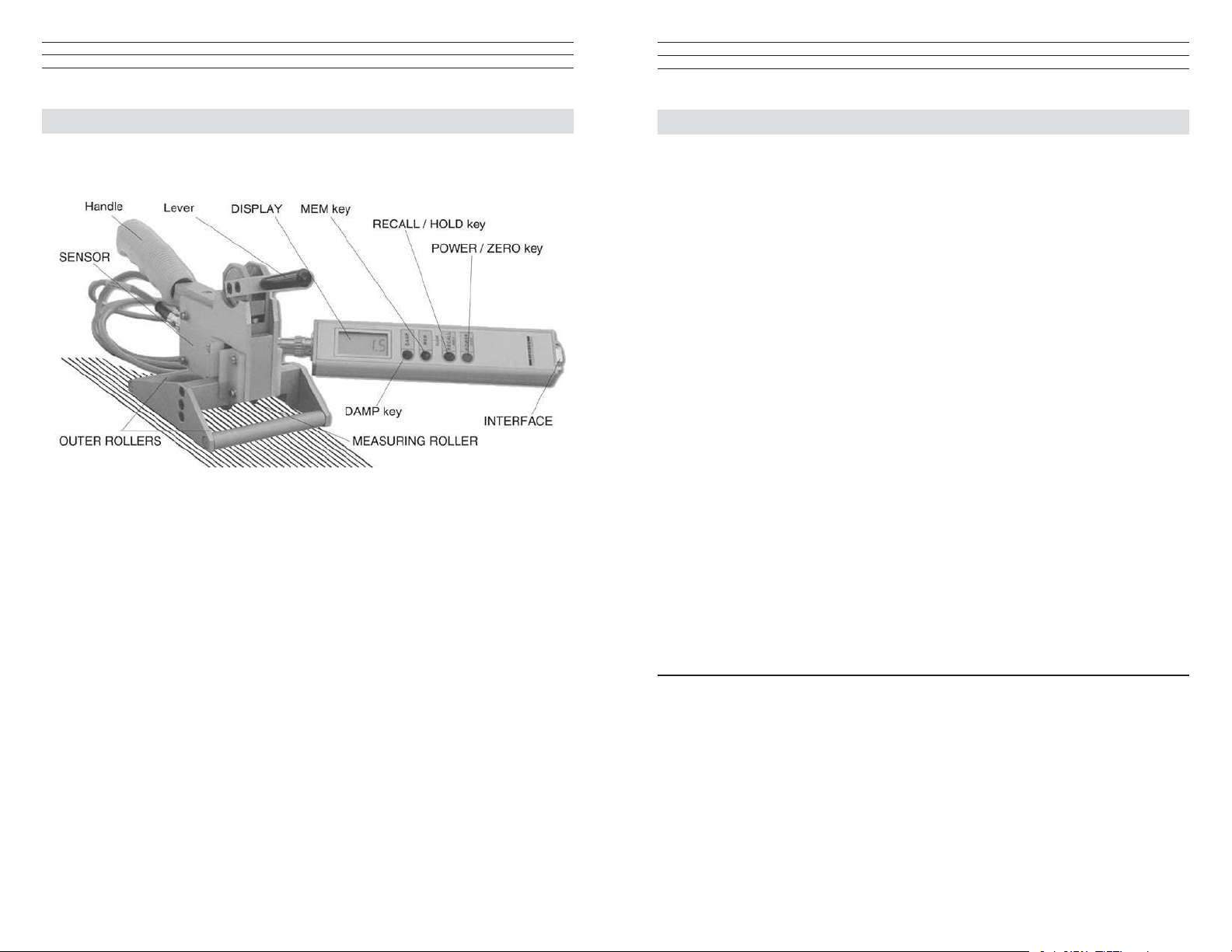
2.0 Overview
12.0 Specifications
2.1 Controls
2.2 Complete kit
• XLETensionMeter.
•9voltbattery.
•Digitalconnectingcable.PartnumberETC-CC.
•TENSIONINSPECTsoftwareforviewingandstoringmeasureddataonaPC,
requires Win 96 or higher. Part number ETC-P2.
•Operatingmanual.
•Carryingcase.
2.3 Optional accesories
Display Unit Calibration According to factory procedure
Units of Measure daN
Accuracy ± 1% FS* ± 1 digit (typically ± 0.5% FS*)
Overrange 10% FS*, without accuracy guarantee
Overload Protection 150% FS*
Measuring Principle Strain gauge bridge
Signal Processing Digital 16 bit A/D converter
Damping Adjustable electronically (averaging)
Measuring Frequency Approx. 5 kHz internally
Display Update Rate 2x per second
Display 4-digit LCD, height of digit 11 mm
Memory Average, last value, MAX, MIN, MAX PEAK, MIN PEAK
Memory Modes 3 - for up to 4000 readings
Temperature Coefficient Gain: less than ± 0.01% FS*/°C
Analog Output Signal 0 - 2 V DC (linearized) RLoad > 1 kΩ ± approx.1%
Converter Frequency 100 Hz
Digital Output Signal RS232 (9600, 8, N, 1) (2 readings per sec.)
(with Tension Inspect > 50 readings/sec possible)
Temperature Range 10 - 45 ° C
Air Humidity 85% RH, max.
Auto Power Off Automatically after approx. 3 min. of non-use
Power Supply 9 V E block
9 V lithium for about 80 hours of continuous use
Housing Material Aluminium profile with plastic outer casing (PVC)
Housing Dimensions 230 mm x 45 mm x 48 mm (L x W x H)
Weight, net
(gross) Approx. 370 g / 1050 g *FS = Full Scale
ETX-CA Connecting cable for analog signal.
ET-AKKU Rechargeable 9 V battery (NiCd).
ET-AC-115 Battery charger for 115 V AC.
ET-AC-230 Battery charger for 230 V AC.
– 4 –
Sensor:
Measuring Rollers 2x 22 mm ball bearing rollers
Width of Outer Rollers 100 mm (ball bearing rollers)
Total Width of Rollers 50 mm
Reference Frame Height
Adjustment 24 mm
Material Anodized aluminium
Dimension 165 x110 x 140 mm (L x W x H)
Weight, net
(gross) 1050 g (1500 g)
– 25 –
Page 5
.6
Peak Mem Damp g cN
Peak Mem Damp g cN
8.8.8.8
11.0 PC Communication (RS-232-C Interface)
11.1 The TENSION INSPECT Program
The TensionInspect software from Electromatic is described in a separate user manual.
11.2 WINDOWS Terminal Program
The measured values and the memory contents can be transmitted over the RS232
interface to a personal computer. You can connect the computer to the INTERFACE of
the KXE by using the ETX-CC special cable which is available as an accessory.
The pin assignment of the INTERFACE is described in Section 13.
Requirements: A communication program, such as Termina or HyperTerminal
(provided on MS Windows Version 3.0 or later), must be installed and configured on
the computer.
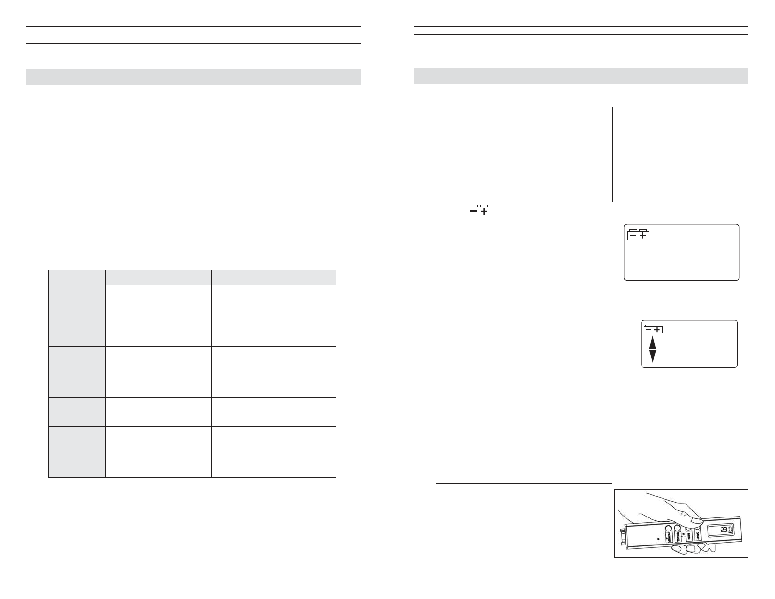
3.0 Set-Up Procedures
3.1 Battery insertion and replacement
Before the first use of your tension meter, you
need to insert the battery
1. Open the battery compatment on the rear
side of the tension meter and insert a
9V battery (E Block), making sure that the
polarity of the battery matches the polarity
marked on the battery compartment. Close
the battery compartment.
2. If the
display, the battery is low and must
be replaced immediately. Operating the
tension meter with a low battery may cause
measurement errors.
symbol is shown on the
Photo Battery
Compartment
ASCII Code Function Description
D Continuous transmission Continuous transmission of
the readings. press any key to
stop transmission.
d Send Transmit current reading to
PC once.
m Save Start logging of measuring
date. Stop data logging.
r Output Output the memory contents
to the PC.
c Clear memory Delete the memory content.
a Damping ON/OFF Switch damping on or off.
z Zero Carry ot zero adjustment of
the instrument
u Toggle unit of measure Switch from g to cN, and vice
versa
NOTE: If the instrument will not be used for
an extended period of time, the battery should
be removed.
3.2 Power On/Off
Power On: Press the POWER/ZERO key until all
symbols are shown on the display. When you release
the key, the display momentarily shows the tension
range and the shoftware version, e.g. E 1.0, followed
by random valuse or “0.”
Power Off: Press the POWER/ZERO key for 5 seconds.
Auto Power Off: The tension meter switches off after 3 minutes of non use.
3.3 Reversing the display
When you shift the tension meter from the right to the left hand, you can rotate the
readings on the DISPLAY by 180° to make them easier to read.
Measuring with the display unit in the left hand:
1. Switch off the tension meter switched off as
described in Section 3.
2. Press and hold the DAMP and POWER
keys until the display shows the readings
the other way around.
– 24 –
– 5 –
Page 6

Measuring with the display unit in the right hand (default position):
1. Tension meter switched off as described in
Chapter 3.2
2. Press and hold the DAMP and POWER
keys until the display shows the readings
in the default position.
NOTE: The selected display orientation
remains stored in the KXE memory even after
the instrument is switched off.
3.4 Zero adjustment of the measuring position.
Before starting measurement you need to carry out zero adjustment,
as described below, each time the tension meter is switched on. This
procedure is necessary to compensate for the weight of the measuring
roller in the measuring position. The zero adjustment for the new
measuring path only remains effective until the instrument is switched
off. Zero adjustment must be repeated whenever the material path is
changed or the tension meter does not display “0.”
NOTE: The process material must not yet be inserted into the tension
meter!
To carry out a zero adjustment:
1. Holding the SENSOR at the HANDLE, place it in the desired measuring position.
Be careful to hold the instrument absolutely steady.
10.0 Error Messages
EEE
cN
The DISPLAY shows EEE. The upper limit of the tension range was
exceeded by more than 10%. Reduce the line tension.
OR
AUTO ZERO is no longer possible. Recalibrate the instrument
following the directions in Section 3.4.
-EEE
cN
The DISPLAY shows -E.E. The lower limit of the tension range was
fallen below by more than 10%. Properly insert the process material.
OR
AUTO ZERO is no longer possible. Recalibrate the instrument
following the directions in Section 3.4.
6
cN
The DISPLAY shows the battery symbol. The battery is low and must
be replaced immediately. Operating the tension meter with a low
battery may cause measurement errors.
2. Press the POWER key.
The display momentarily shows
The KXE is now adjusted for the new material path and is ready to measure.
0000
– 6 –
and then switches to
0
.
– 23 –
Page 7

9.0 Memory Management
9.1 Clearing the KXE Memory
If values are stored in the KXE memory, the DISPLAY shows e.g.
with the MEM indicator.
To clear the memory:
1. Simultaneously press the MEM and RECALL keys.
3
Mem
4.0 Taking A Measurement
The DISPLAY shows e.g.
deleted.
9.2 Memory Function HOLD
When the tension meter memory is empty, you can retain the last reading on the
DISPLAY by using the memory function HOLD.
To retain the last reading:
1. Press the RECALL / HOLD key once for about 1 second.
3
; all values stored in the memory have been
The DISPLAY shows the last reading
To switch back to measuring mode:
1. Press the RECALL / HOLD key once for about 1 second. The tension meter
switches back to measuring mode.
2:3.3
and the “:” colon symbol.
4.1 Inserting the process material
1. Turn on the power, then perform as zero adjustment as described in Section 3.4.
2. Push the LEVER in the direction of the arrow to lift the REFERENCE FRAME
and the OUTER ROLLERS.
3. Insert the MEASURING ROLLER Into the warp.
4 Push the LEVER back into the original position to move the REFERENCE
FRAME and the OUTER ROLLERS down again. It is important to assure that
the warp passes smoothly between the MEASURING ROLLERS and the OUTER
ROLLERS.
4.2 Measuring the process material:
The display now shows the measured tension values. Error messages which might be
displayed are described in Section 10.0
– 22 –
4.3 Removing the process material:
1. Push the LEVER in the direction of the arrow to lift the REFERENCE FRAME
and the OUTER ROLLERS.
2. Remove the MEASURING ROLLER from the warp.
– 7 –
Page 8

5.0 Damping Mode
The KXE is equipped with an electronic damping which ensures steady readings when
tension fluctuates. This is achieved by averaging the measured values at the set update
rate.
NOTE: Before switching on the damping mode, it is recommended that you measure
the first values without damping enabled.
5.1 To switch damping on and off:
1. Insert process material and take a mesurement as directed in Section 4.0
3. The DISPLAY blinks, showing
measuring period (POS: 1) and the
4. Press the RECALL key. The DISPLAY blinks, showing
last value (LAST) of the measuring period.
5. Press the RECALL key. The DISPLAY blinks, showing
maximum value (MAX) of the measuring period and the
22
symbol.
the average value (AVG) of the first
23
24
symbol.
the
the
2. Press the DAMP key. The display shows the set damping factor.
3. Release the DAMP key.
The display shows DAMP below the currently measured value.
3. To switch off damping, press the DAMP key again.
The display shows only the currently measured value.
5.2 Modifying the Dampling Factor
The tension meter is factory preset to a damping factor of 12. The tension values are
averaged for the display in the following way:
12 old values + 4 new values
16
The damping factor can be modified in 15 steps from 01 = low damping:
1 old value + 15 new values
16
to 15 = high damping:
15 old values + 1 new value
16
0000
0000
Damp
Peak
21
symbol.
26
Peak
showing the
6. Press the RECALL key. The DISPLAY blinks, showing
minimum value (MIN) of the measuring period and the
7. Press the RECALL key. The DISPLAY blinks, showing
maximum peak value (PEAK MAX) of the measuring period, the PEAK indicator
and the
8. Press the RECALL key. The DISPLAY blinks,
minimum peak value (PEAK MIN) of the measuring period, the PEAK indicator
and the
9. Press the RECALL key. The measured values no. 1 — 10 of the first measuring
period can be recalled.
10. Press the RECALL key. The next measuring period (POS: 2) is shown on the
DISPLAY and the sequence is repeated, starting with the average value (AVG).
symbol.
19
symbol.
the
the
– 8 –
– 21 –
Page 9

26
7. Press the RECALL key. The DISPLAY blinks, showing
Peak
maximum peak value (PEAK MAX) of the measuring period, the PEAK indicator
and the
8. Press the RECALL key. The DISPLAY blinks,
symbol
19
Peak
showing the
minimum peak value (PEAK MIN) of the measuring period, the PEAK indicator
and the
symbol.
9. Press the RECALL key. The measured values no. 1 — 10 of the first measuring
period can be recalled.
10. Press the RECALL key. The next measuring period (POS: 2) is shown on the
DISPLAY and the sequence is repeated, starting with the average value (AVG).
8.4 Recalling the Stored Tension Values in Mode “F“ FAST
1. Tension meter switched on as described in Chapter 3.3.1.
2. Press the RECALL key.
NOTE: You can end recall any time by pressing the POWER key.
Memory Mode CONTINUOUS
Pos: 1 Pos: 12 Pos: 3 Pos:
AVG: 22.0 AVG: 12.0 AVG: 12.0 AVG:
Last: 23.0 Last: 22.1 Last: 22.1 Last:
MAX: 24.0 MAX: 22.1 MAX: 22.1 MAX:
MIN: 21.0 MIN: 5.4 MIN: 5.4 MIN:
PEAK
PEAK
: 26.0 PEAK
MAX
: 19.0 PEAK
MIN
10.8 14.2 14.1
10.0 19.4 11.2
7.3 22.9 8.9
6.1 17.3 10.2
n n n
: 28.1 PEAK
MAX
: 1.8 PEAK
MIN
: 28.1 PEAK
MAX
: 1.8 PEAK
MIN
MAX
MIN
the
:
:
12.0
22.1
22.1
5.4
28.1
1.8
15.4
18.3
17.5
7.8
5.3 Setting a new Damping Factor
1. Press and hold the DAMP key. The display shows the set damping factor.
2. You can now increase the damping factor by pressing the MEM key and decrease it
by pressing the RECALL key.
3 Once the new factor appears on the display, release the DAMP key. The tension
meter switches back to measuring mode.
NOTE: The selected damping factor remains stored in the KXE memory even after the
instrument is switched off.
6.0 Memory Modes
The tension meter features a data
logger with a memory capacity for
up to 4000 readings, with which
you can store different measuring
periods at one or more machine
positions. The readings are saved 2x
per second, synchronously with the
display update rate, in all memory
modes except the “F” mode in which
they are saved 100x per second. All
saved readings and statistics can be
4
shown on the display or transmitted
to a PC (e.g. for further processing in Excel). The memory can be allocated to different
measuring periods, depending on the memory mode.
NOTE: The selected memory mode remains stored in the KXE memory even after the
instrument is switched off.
Memory mode “S” STANDARD (default)
The following values of a measuring period are calculated and saved at a rate of 2
readings per second:
Average value,
Last value,
Maximum value (MAX),
Minimum value (MIN),
Minimum peak value (MIN PEAK)
n
Maximum peak value (MAX PEAK)
Individual readings are not saved. You can save up to 255 measuring periods.
Memory Mode S C L F
Meas. periods,
max.
Readings, max.
Max. no. of
readings per
position
Statistics
Save Readings
255 255 255 255
– 4000 4000 4000
– Any 10 Any
Yes Yes Yes Yes
– Yes Yes Yes
– 20 –
– 9 –
Page 10

Memory mode “C” CONTINUOUS:
The following values of a measuring
period are calculated and all readings are additionally saved at a rate of 2 readings per
second:
Average value,
Last value,
Maximum value (MAX),
Minimum value (MIN),
Minimum peak value (MIN PEAK)
Maximum peak value (MAX PEAK)
You can save up to 4000 readings, split up into up to 255 measuring periods.
Memory mode “L” LIMIT:
The following values of a measuring period are calculated and 10 readings are
additionally saved at a rate of 2 readings per second:
Average value,
Last value,
Maximum value (MAX),
Minimum value (MIN),
Minimum peak value (MIN PEAK)
Maximum peak value (MAX PEAK)
You can save up to 255 measuring periods with 10 readings each.
8.3 Recalling the Stored Tension Values in Mode “L“ LIMIT
1. Tension meter switched on as described in Chapter 3.2.
2. Press the RECALL key.
NOTE: You can end recall any time by pressing the POWER key.
Memory Mode CONTINUOUS
Pos: 1 Pos: 12 Pos: 3 Pos:
AVG: 22.0 AVG: 12.0 AVG: 12.0 AVG:
Last: 23.0 Last: 22.1 Last: 22.1 Last:
MAX: 24.0 MAX: 22.1 MAX: 22.1 MAX:
MIN: 21.0 MIN: 5.4 MIN: 5.4 MIN:
PEAK
PEAK
: 26.0 PEAK
MAX
: 19.0 PEAK
MIN
10.8 14.2 14.1
10.0 19.4 11.2
7.3 22.9 8.9
6.1 17.3 10.2
n 10 10
: 28.1 PEAK
MAX
: 1.8 PEAK
MIN
: 28.1 PEAK
MAX
: 1.8 PEAK
MIN
MAX
MIN
4
12.0
22.1
22.1
5.4
:
28.1
:
1.8
15.4
18.3
17.5
7.8
10
Memory mode “F” FAST:
The following values of a measuring period are calculated and all readings are
additionally saved at a rate of 100 readings per second:
Average value,
Last value,
Maximum value (MAX),
Minimum value (MIN),
Minimum peak value (MIN PEAK)
Maximum peak value (MAX PEAK)
You can save up to 4000 readings, split up into up to 255 measuring periods.
– 10 –
3. The DISPLAY blinks, showing
measuring period (POS: 1) and the
22
symbol.
the average value (AVG) of the first
4. Press the RECALL key. The DISPLAY blinks, showing
last value (LAST) of the measuring period.
5. Press the RECALL key. The DISPLAY blinks, showing
maximum value (MAX) of the measuring period and the
6. Press the RECALL key. The DISPLAY blinks, showing
minimum value (MIN) of the measuring period and the
– 19 –
23
24
symbol.
21
symbol.
the
the
the
Page 11

Peak
24
symbol.
21
symbol.
26
Peak
showing the
the
the
the
5. Press the RECALL key. The DISPLAY blinks, showing
maximum value (MAX) of the measuring period and the
6. Press the RECALL key. The DISPLAY blinks, showing
minimum value (MIN) of the measuring period and the
7. Press the RECALL key. The DISPLAY blinks, showing
maximum peak value (PEAK MAX) of the measuring period, the PEAK indicator
and the
8. Press the RECALL key. The DISPLAY blinks,
minimum peak value (PEAK MIN) of the measuring period, the PEAK indicator
and the
9. Press the RECALL key. The measured values no. 1 — n of the first measuring
period can be recalled.
10. Press the RECALL key. The next measuring period (POS: 2) is shown on the
DISPLAY and the sequence is repeated, starting with the average value (AVG).
symbol
19
symbol.
6.1 Memory Mode Selection
1. Turn on the tension meter and clear the memory by simultaneously pressing the
MEM and RECALL keys.
2 Press and hold the MEM key. The display shows S
DAMP or RECALL key to change the memory mode.
MEMORY MODE “S” STANDARD (default)
If the display shows S. The STANDARD memory mode is set.
MEMORY MODE “C” CONTINUOUS
If the DISPLAY shows C, the CONTINUOUS memory mode is set.
MEMORY MODE “L” LIMIT
If the DISPLAY shows L , the LIMIT memory mode is set.
MEMORY MODE “F” FAST
If the DISPLAY shows F , the FAST memory mode is set.
When you have selected the desired memory mode, you can release the MEM key. The
selected memory mode is now active and the tension meter switches back to measuring
mode.
L
F
C
S
S
. Press the
– 18 –
NOTE: The selected memory mode remains stored in the KXE memory even after the
instrument is turned off.
7.0 Data Logging
7.1 Data Logging in Mode “S” Standard
1. Turn on the tension meter and select the “S” Standard Memory Mode as described
in Section 6.1.
2. Insert the process material as described in Section 4.1.
3. To save the first measuring period, press and hold the MEM key
until the display shows the memory mode “S” and the current
memory number .
4. Release the MEM key.
The tension meter starts logging the data.
– 11 –
S1
Page 12

3
Mem
While the tension data are stored, the MEM indicator blinks
display and the currently measured value is displayed
To stop data logging:
When you want to end the measuring period, press the MEM key once again. The
statistical values are calculated from the logged tension data and stored in the following
order:
on the
19
8. Press the RECALL key. The DISPLAY blinks,
minimum peak value (PEAK MIN) of the measuring period, the PEAK indicator
and the
9. Press the RECALL key. The next measuring period (POS: 2) is shown on the
DISPLAY, starting at the beginning of the sequence with the average value (AVG).
symbol.
Peak
showing the
Average value,
Last value,
Maximum value (MAX),
Minimum value (MIN),
Minimum peak value (MIN PEAK),
Maximum peak value (MAX PEAK).
3
The MEM
tension meter shows the current reading and changes back to measuring mode.
To save the next measuring period:
1. Press the MEM key again. The display shows the memory mode “S” and the next
memory number
7.2 Data Logging in Mode “C” Continuous
1. Turn on the tension meter and select the “C” Continuous Memory Mode as
described in Section 6.1.
2. Insert the process material as described in Section 4.1.
3. To save the first measuring period, press and hold the MEM key
until the display shows the memory mode “C” and the current
memory number .
Mem
indicator stops blinking and remains on the display. The
S2
. You can save up to 255 measuring periods.
C1
8.2 Recalling the Stored Tension Values in Mode “C“ CONTINUOUS
1. Tension meter switched on as described in Chapter 3.2.
2. Press the RECALL key.
NOTE: You can end recall any time by pressing the POWER key.
Memory Mode CONTINUOUS
Pos: 1 Pos: 12 Pos: 3 Pos:
AVG: 22.0 AVG: 12.0 AVG: 12.0 AVG:
Last: 23.0 Last: 22.1 Last: 22.1 Last:
MAX: 24.0 MAX: 22.1 MAX: 22.1 MAX:
MIN: 21.0 MIN: 5.4 MIN: 5.4 MIN:
PEAK
PEAK
: 26.0 PEAK
MAX
: 19.0 PEAK
MIN
10.8 14.2 14.1
10.0 19.4 11.2
7.3 22.9 8.9
6.1 17.3 10.2
n n n
: 28.1 PEAK
MAX
: 1.8 PEAK
MIN
: 28.1 PEAK
MAX
: 1.8 PEAK
MIN
MAX
MIN
:
:
4
12.0
22.1
22.1
5.4
28.1
1.8
15.4
18.3
17.5
7.8
n
4. Release the MEM key. The tension meter starts logging the data.
While the tension data are stored, the MEM indicator blinks
display and the currently measured value is displayed.
– 12 –
3
Mem
on the
3. The DISPLAY blinks, showing
measuring period (POS: 1) and the
4. Press the RECALL key. The DISPLAY blinks, showing
last value (LAST) of the measuring period.
22
symbol.
– 17 –
the average value (AVG) of the first
23
the
Page 13

8.0 Recalling the stored tension values
Using the TENSION INSPECT software included with your tension meter, you can
easily and accurately evaluate the stored tension values and export them to an Excel
sheet.
8.1 Recalling the Stored Tension Values in Mode “S“ STANDARD
1. Tension meter switched on as described in Chapter 3.2.
2. Press the RECALL key.
NOTE: You can end recall any time by pressing the POWER key.
Memory Mode STANDARD
Pos: 1 Pos: 12 Pos: 3 Pos:
AVG: 22.0 AVG: 12.0 AVG: 12.0 AVG:
Last: 23.0 Last: 22.1 Last: 22.1 Last:
MAX: 24.0 MAX: 22.1 MAX: 22.1 MAX:
MIN: 21.0 MIN: 5.4 MIN: 5.4 MIN:
PEAK
PEAK
: 26.0 PEAK
MAX
: 19.0 PEAK
MIN
: 28.1 PEAK
MAX
: 1.8 PEAK
MIN
: 28.1 PEAK
MAX
: 1.8 PEAK
MIN
MAX
MIN
To stop data logging:
When you want to end the measuring period, press the MEM key once again. The
statistical values are calculated from the logged tension data and stored in the following
order:
Average value,
Last value,
Maximum value (MAX),
Minimum value (MIN),
Minimum peak value (MIN PEAK),
Maximum peak value (MAX PEAK).
Tension Value - 1 Tension Value - 2 -
4
12.0
22.1
22.1
5.4
:
28.1
:
1.8
To save the next measuring period:
Tension Value - N - (up to 4000 tension values in up to 255 measuring periods)
3
The MEM
tension meter shows the current reading and changes back to measuring mode.
1. Press the MEM key again. The display shows the memory mode “C” and the next
Mem
indicator stops blinking and remains on the display. The
3. The DISPLAY blinks, showing
measuring period (POS: 1) and the
4. Press the RECALL key. The DISPLAY blinks, showing
last value (LAST) of the measuring period.
5. Press the RECALL key. The DISPLAY blinks, showing
maximum value (MAX) of the measuring period and the
6. Press the RECALL key. The DISPLAY blinks, showing
minimum value (MIN) of the measuring period and the
7. Press the RECALL key. The DISPLAY blinks, showing
maximum peak value (PEAK MAX) of the measuring period, the PEAK indicator
and the
symbol
22
symbol.
– 16 –
the average value (AVG) of the first
23
24
symbol.
21
symbol.
26
Peak
the
the
the
the
memory number
maximum of 4000 readings.
7.3 Data Logging in Mode “L” Limit
1. Turn on the tension meter and select the “L” Limit Memory Mode as
described in Section 6.1.
2. Insert the process material as described in Section 4.1.
3. To save the first measuring period, press and hold the MEM key
until the display shows the memory mode “L” and the current
memory number .
4. Release the MEM key. The tension meter starts logging the data.
While the tension data are stored, the MEM indicator blinks
display and the currently measured value is displayed.
C2
. You can save up to 255 measuring periods with a
3
Mem
– 13 –
L1
on the
Page 14

To stop data logging:
When you want to end the measuring period, press the MEM key once again. The
statistical values are calculated from the logged tension data and stored in the following
order:
Average value,
Last value,
Maximum value (MAX),
Minimum value (MIN),
Minimum peak value (MIN PEAK),
Maximum peak value (MAX PEAK).
Tension Value - 1 Tension Value - 2 -
Tension Value - 10 - (up to 10 tension values in up to 255 measuring periods)
3
The MEM
tension meter shows the current reading and changes back to measuring mode.
To save the next measuring period:
1. Press the MEM key again. The display shows the memory mode “L” and the next
memory number
maximum of 10 readings each.
7.4 Data Logging in Mode “F” Fast
1. Turn on the tension meter and select the “F” Fast Memory Mode as
described in Section 6.1.
2. Insert the process material as described in Section 4.1.
3. To save the first measuring period, press and hold the MEM key
until the display shows the memory mode “L” and the current
memory number .
4. Release the MEM key. The tension meter starts logging data at the rate of 100
readings per second
While the tension data are stored, the MEM indicator blinks
display and the currently measured value is displayed.
Mem
indicator stops blinking and remains on the display. The
L2
. You can save up to 255 measuring periods with a
F1
3
Mem
on the
Tension Value - N - (up to 4000 tension values in up to 255 measuring periods)
3
The MEM
tension meter shows the current reading and changes back to measuring mode.
To save the next measuring period:
1. Press the MEM key again. The display shows the memory mode “F” and the next
memory number
maximum of 4000 readings.
Mem
indicator stops blinking and remains on the display. The
F2
. You can save up to 255 measuring periods with a
8.0 Recalling the stored tension values
Using the TENSION INSPECT software included with your tension meter, you can
easily and accurately evaluate the stored tension values and export them to an Excel
sheet.
8.1 Recalling the Stored Tension Values in Mode “S“ STANDARD
1. Tension meter switched on as described in Chapter 3.2.
2. Press the RECALL key.
NOTE: You can end recall any time by pressing the POWER key.
– 14 –
– 15 –
Page 15

CHECK•LINE
BY ELECTROMATIC
Warp Tension Meter
Model KXE
®
CHECK•LINE
INSTRUMENTS
®
ELECTROMATIC
E Q U I P M E N T C O., I N C.
600 Oakland Ave., Cedarhurst, NY 11516 – USA
TEL:516-295-4300•FAX:516-295-4399
Operating Instructions
 Loading...