

Page 1
J-CC Data Cable
Operating Instructions
Page 2
User's manual for OPTO-RS cable connections
General
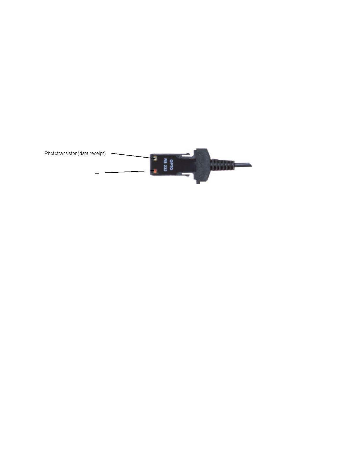
The OPTO-RS cable enables a direct connection with most of the Käfer measuring instruments to a personal
computer, a dedicated printer or to a Käfer display unit.
It is not only a cable, but an interface which converts the data output of the instrument to a compatible RS232
signal. The periphery instrument connection must be able to supply power to the OPTO-RS plug.
Definition
RS232 communication parameters
4800 baudrate, even parity, 7 data bits, 2 stop bits
Data format
Data
[ Sign ¦ E1-En ¦ "." ¦ F1-Fn ¦ CR ] Sign : « + », « - », or « space »
E1-En: integer
F1-Fn: fractional
n: depends on used unit and resolution
Errors
[ "ERR" ¦ Number ¦ CR ]
0: sensor error (e.g. speed, scale distance) 1: incorrect command
2: parity error (duplex instruments only) 3: exceeded measurement range
Identification
[ "SY" ¦ Instr. ¦ "." ¦ OPT1 ¦ {"." ¦ OPT2} ¦ CR ]
SY: Sylvac Instr: 203, 235, 233, etc OPT1: version option OPT2: additional version options (according to
instrument used) Note: The id. transmission is done only when switching ON the instrument
Connection description
Page 3
Two different types of OPTO-RS plug connections are available: Simplex and Duplex
Simplex cable
First generation of OPTO-RS cable connection, designed for instruments which were not able to receive RS232
commands. Data requests are made by LED status change (e.g. by turning off the DTR signal line for a
minimum of 110ms). The OPTO-RS simplex cable can also be used with duplex instruments, however remote
commands will be ignored.
The simplex cable can be directly connected to any standard program as "HyperTerminal" provided with
Windows.
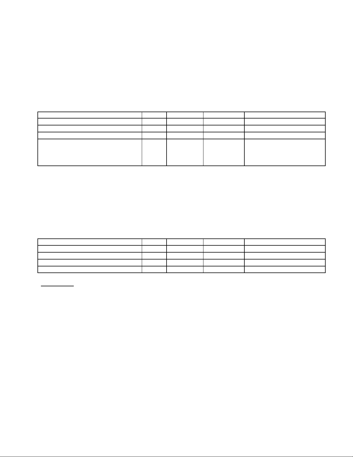
Connections
Line definition Name Sub-D 9 pin Cable color Line status
Positive power supply : RTS 7 white ON (HIGH)
Negative power supply TXD 3 brown OFF (LOW)
Data (instrument to periphery) RXD 2 yellow INPUT
Data request: Standard status Data
request
Duplex cable
The duplex cable allows a 2-way communication between an instrument and a PC in half-duplex mode (e.g. 2way communication but not simultanuously).
Important : Only Duplex instruments have the ability to receive RS232 commands. If you use a Duplex cable
with a simplex instrument, all commands other than "?" will be seen as a data request.
The pin assignment of a duplex cable is different to the one of a simplex cable.
DTR 4 green
ON (HIGH) OFF (LOW) during
min. 110m sec.
Connections
Line definition Name Sub-D 9 pin Cable color Line status
Positive power supply : DTR 4 white ON (HIGH)
Negative power supply RTS 7 brown OFF (LOW)
Data (instrument to periphery) RXD 2 yellow INPUT
Data request: TXD 3 green "?" + <CR>
Note :
In case of data sending from the instrument, the hold mode will be active. To disable the Hold
mode simply do a new data request.
Remote commands
Format
[¦ C1-Cn ¦ { S1-Sn } ¦ CR ]
C1-Cn: command of 2 to 3 characters
S1-Sn: 0/1 : command disabled/activated
?
: status request
+XXX.YYY: entering numerical values
Page 4

List of remote commands
This list shows the main remote commands applied using DUPLEX instruments.
<NOR>
<MOD?>
<STO0>, <STO1>
<RST>
<SET?>
<ID?>
<OUT0>, <OUT1>
<OFF>
<ON>
<PRI>, <?>
<MM>, <IN>
<RES2>, <RES3>
<REF1>, <REF2>
<PRE>
Places the instrument in Measuring mode (or in Reference mode if the keyboard is
disabled)
The instrument sends its operating mode (NOR, REF, MIN, MAX, DEL, TOL1)
Disables, enables measuring value freeze
Resets the instrument to its initial parameters
The instrument sends its main parameters: (MM RES2 REF1 etc)
Note: B1 battery OK , B0 replace the battery
The instrument sends its identification code:
Disables, enables continuous transfer of the displayed value
Switches off the instrument
Switches on the instrument (No command echo when the instrument is switched on !)
The instrument sends the displayed value. Note: in tolerance mode, the value is followed
by the symbols ‘<‘, ‘=‘ or ‘>‘.
Changes the measurement unit
Changes the resolution: <RES2>: 0.001 mm, <RES3>: 0.01 mm
Changes the reference
Recalls the preset
Refer to the user’s manual of the specific instrument for special applications.
Program samples
Standard Basic
Simplex cable
Serial port opening and parameters OPEN "COM1:4800,E, 7, 2, PE"
Power supply setting OUT &H3FC,&H0B
(RTS=ON, DTR = ON)
&H3FC register addresse (COM2: &H2FC)
Set DTR line OFF OUT &H3FC,&H0A
(RTS=ON, DTR = OFF)
Data reading Line input #1,a$
Duplex cable
Serial port opening and parameters OPEN "COM1:4800, E, 7, 2, PE"
Power supply setting OUT &H3FC,&H09
(RTS=OFF, DTR = ON)
&H3FC register addresse (COM2: &H2FC)
Data request (<CR> will be automatic using this PRINT #1, "?"
command)
Data reading LINE INPUT #1,a$
Page 5

Visual Basic
The communication control (MsComm) of VisualBasic must be applied :
Port opening ' Use COM1.
Comm1.CommPort = 1
' 4800 baud, even parity, 7 data, and 2 stop bit. Comm1.Settings = "4800,E,7,2"
Power supply setting ' Simplex Cable' Form1.MSComm1.DTREnable = True
' Open the port. Comm1.PortOpen = True
Form1.MSComm1.RTSEnable = True
Data request ' Simplex Cable' MSComm1.DTREnable = False
' Duplex Cable' Form1.MSComm1.DTREnable = True
Form1.MSComm1.RTSEnable = False
Timer1.Interval = 150
Timer1.Enabled = True
'Duplex cable + duplex instrument' MSComm1.Output = "?" + Chr$(13)
'Duplex cable + simplex instrument' MSComm1.Break = True
'Incremente Timer1.Interval in case of no transmission'
Timer1.Interval = 10
Timer1.Enabled = True
Data reading InString$ = Comm1.Input
MSComm1.Break = False
For more information, refer to the help menu of MSComm in Visual Basic. Program available on
www.sylvac.ch web site.
Application program
OPTO-RS test
This program is available free of charge on the Sylvac web site or at your distributor. It is a Visual
Basic program with all source files for testing connections and transmission.
Winwedge
WinWedge is designed to transfer any data obtained using Käfer measuring instruments to a computer
application program running under Windows.
Different versions of the Winwedge program are available (light, professional, Windows CE). For
more information contact TAL Technologies, Inc. or consult the www.taltech.com web site.
A light version of WinWedge named GageWedge is available at your distributor. However, this program
version has restrictions regarding data transfer from the instrument.
Hyperterminal
This program is available as standard with Windows 95, 98, 2000 and Me (millenium). It can only be used with a
simplex cable and as data transmission from the instrument.
Page 6

Parameter:
-In menu [connect to], select[connection using] Directed to {n}
– In menu [parameter], select[terminal keyboard] Suppr. [emulation] ANSI
-In menu [port parameters], select :
Specifications
[bits/sec]
[data bits]
[parity]
[stop bits]
[Flux control]
4800
7
Even
2
None
Connection ......................................................... RS232 compatible, Dsub 9p female or open
Power supply...................................................... from periphery, with TXD, DTR and RTS lines
Data transmission parameters ............................. 4800 bds, even parity, 7 data bits, 2 stop bits
Max. cable length................................................ 15 m according to IEC standards
Number of transmissions /sec.............................. 4-8/sec (depends on the instrument connected)
Data transmission format..................................... [ Sign ¦ E1-En ¦ "." ¦ F1-Fn ¦ CR ]
[ "ERR" ¦ Number ¦ CR ]
15
Page 7

Option
Important : always check the cable output depending on used measuring instrument.
Accessories
Simplex-Duplex adaptor with
foot pedal input (Binderplug 719)
The foot pedal input must be software
aided (CTS input).
Foot pedal with Binder plug
 Loading...